
Abstract
This study investigates the drilling performance of Polyamide 6 (PA6) composites reinforced with 30 wt% rock wool mineral fiber. The composite plates were fabricated via twin-screw extrusion and injection molding. Drilling experiments were performed on a 3-axis CNC machine using HSS, TiN-coated HSS, and Carbide bits to evaluate delamination, surface roughness (µm), and thrust force. Results indicated that higher cutting speeds generally reduced delamination by enhancing bit stability, whereas increased feed rates raised surface roughness due to higher cutting forces and vibrations. Specifically, at 20 m/min cutting speed and 0.1 mm/rev feed rate, the carbide drill bit achieved the lowest delamination factor (5.115) compared to HSS (5.23). Among the tested tools, carbide bits demonstrated the most effective performance regarding initial hole quality and delamination control. While advantageous for structural integrity, further quantitative research on wear progression is required to comprehensively evaluate long-term tool life.
Introduction
Polyamide 6 (PA6), stands out with its excellent combination of mechanical and chemical properties, making it an important material with a wide range of applications among engineering polymers. Its high tensile strength, providing resistance to stress, offers a critical advantage especially for structural parts and load-bearing elements. The high impact resistance reduces the risk of fracture or cracking in applications exposed to sudden loads and impacts. While flexural strength indicates the material’s flexibility and resistance to bending forces, wear resistance extends the material’s service life in areas where friction occurs.1–4 PA6 also demonstrates chemical resistance to oils, greases, many organic solvents, and bases, making it safe to use in various industrial environments. Its moderate heat resistance ensures PA6 retains its properties within a specific temperature range, while its ease of processability makes it compatible with a wide variety of production methods such as injection molding, extrusion, and 3D printing.4–6 The combination of these properties enables PA6 to find application in a wide range of sectors, from automotive (in engine parts and fuel systems) to electrical/electronics (in connectors and insulation elements), textile (in durable fibers and ropes), and packaging (in food packaging and film applications). It is particularly preferred in many critical applications such as engine parts, gears, bearings, connectors, cable ties, textile fibers, ropes, and food packaging. The versatility, cost-effectiveness, and ease of formability of PA6 make it an indispensable and frequently preferred material for engineering applications. Therefore, PA6 is recognized as one of the fundamental building blocks of modern industry.7–9
Rock wool, an inorganic material obtained by melting natural basalt rock at high temperatures and turning it into fibers, has recently been gaining attention as a reinforcement material in composite materials, although it is generally used in thermal and sound insulation applications. Rockforce mineral fiber, produced by Lapinus, stands out as a prominent rock wool product in this field, offering a comparable level of performance to glass fiber reinforcements, especially in terms of stiffness, tensile strength, elongation to break, and impact resistance. Composite materials obtained by using rock wool mineral fiber at a rate of 30%, particularly in matrix materials like polyamide 6 (PA6), play an important role in increasing the overall performance of the material by integrating with the matrix. In addition to improving the mechanical properties of the material, this reinforcement provides advantages such as reducing machine wear, lowering viscosity, controlling shrinkage and warpage, slowing down the burning rate, providing high surface quality, and ensuring dimensional stability. Moreover, it offers a more flexible material option by providing a price advantage compared to glass fiber and low aspect ratio filler materials.10–13
In the production processes of composite materials, drilling operations are an indispensable step for joining parts, assembly, and connecting to other components. Composite materials, which are increasingly used in sectors such as aerospace, automotive, construction, and sports equipment, require the opening of precise and accurate holes during the assembly phase. These drilling operations, necessary for joining and integrating composite parts using fasteners, are a critical process that directly affects the quality and performance of the final product. Therefore, the successful execution of drilling operations is of great importance in the processing of composite materials. However, drilling composite materials also brings along some significant challenges. The heterogeneous structure of composites, consisting of different phases and layers, can lead to the emergence of various damage mechanisms during drilling. Especially in fiber-reinforced composites, issues such as fiber pull-out, fracture, tearing, and most importantly, delamination, a separation between layers, are frequently encountered during drilling.14–17 Delamination can adversely affect the strength of the material, reducing the durability of the final product. Additionally, the surface roughness obtained during the drilling process is also an important factor. Burrs, irregularities, and rough surfaces on the hole edge can cause problems in precision assembly and connection applications. Thrust forces, which are applied by the drill bit during drilling and have the potential to damage the material, are also a concern. Controlling these forces is of great importance for preserving hole quality and material integrity.3,18,19
In conclusion, the drilling performance of composite materials is directly related to parameters such as delamination factor, surface roughness, and thrust forces, and optimizing these parameters determines the final quality of composite parts. Good drilling performance ensures long-lasting, reliable, and high-performance products by maintaining the mechanical properties of composite parts. Therefore, in the processing of composite materials, topics such as optimizing drilling operations, minimizing delamination, controlling surface roughness, and balancing thrust forces are of great importance and these parameters require careful examination.20–23
A review of the literature reveals that while glass fiber reinforcements are widely used in PA6 composites, studies on the drilling performance of rock wool reinforced composites are limited. This study focuses on the drilling performance of PA6 composite materials reinforced with 30% rock wool mineral fiber. In this context, parameters such as surface roughness, delamination factor, and thrust forces generated during the drilling process will be examined, aiming to provide a detailed analysis of the drilling behavior of this composite.
Materials and method
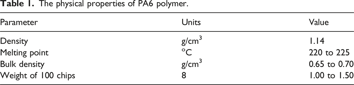
The physical properties of PA6 polymer.
Chemical composition of rock wool mineral fiber.

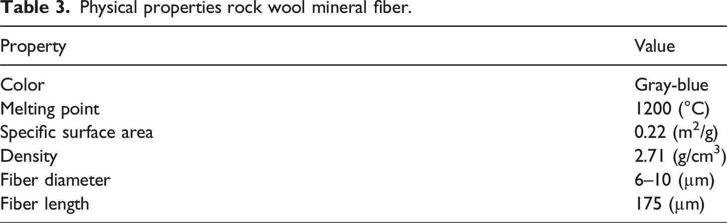
Physical properties rock wool mineral fiber.
The production stages of the rock wool-reinforced PA6 composite plates, including raw material preparation, extrusion, and injection molding, are schematically illustrated in Figure 1. Schematic diagram of the production process for rock wool-reinforced PA6 composite plates.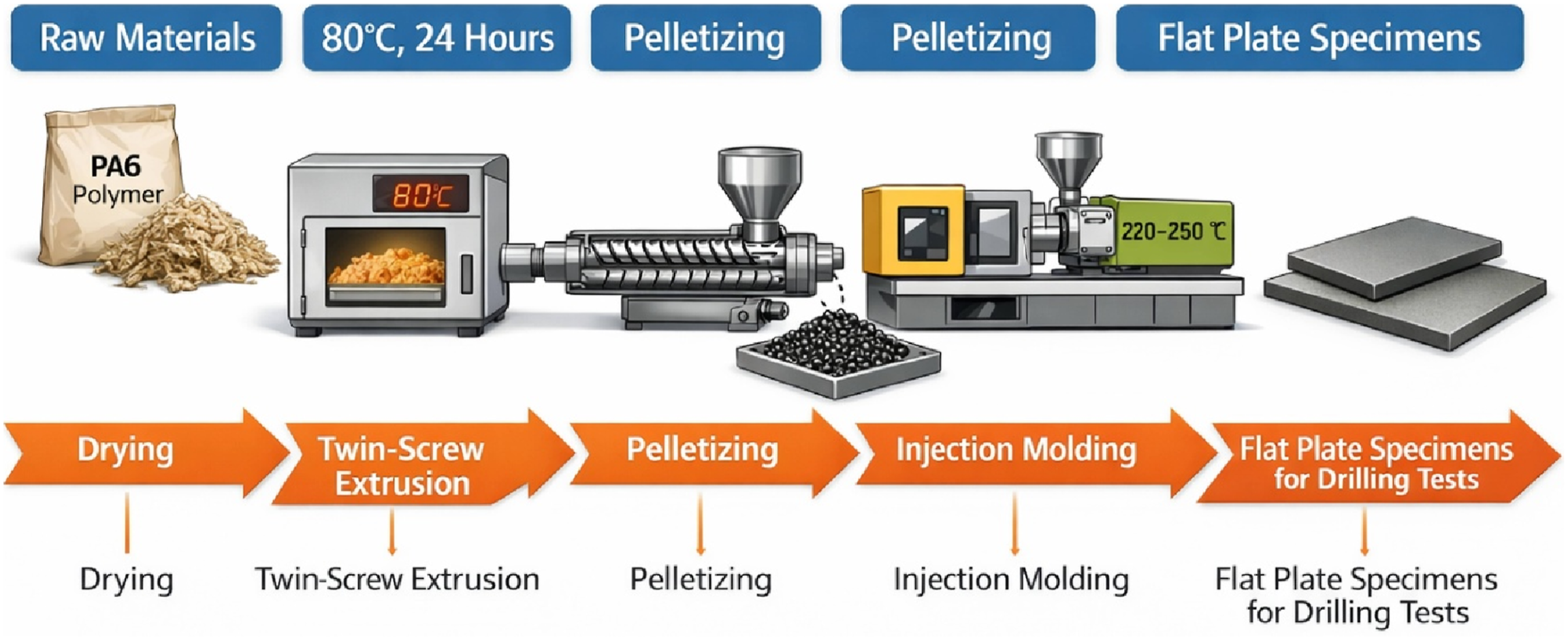
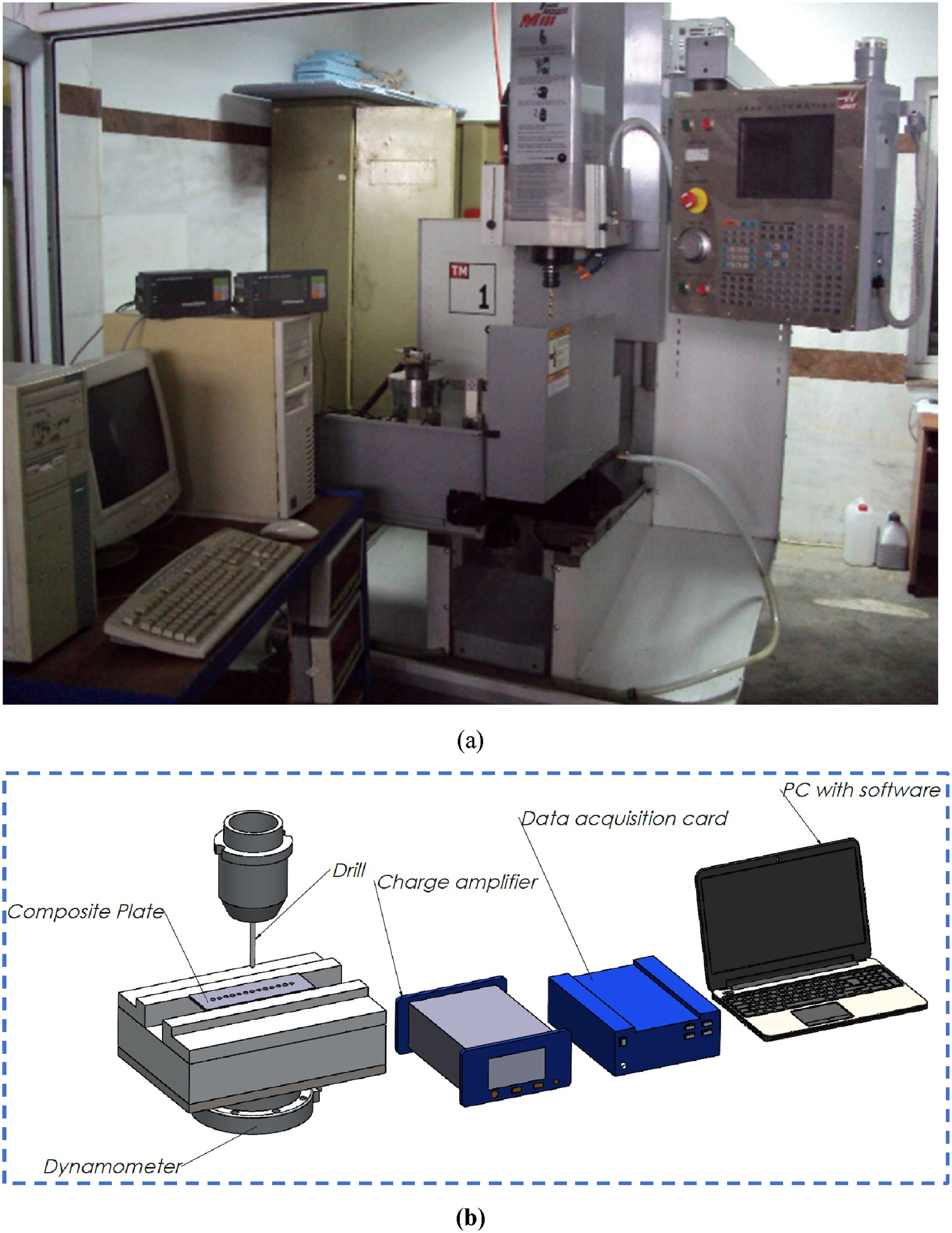
Drilling experiments were conducted using high-speed steel (HSS), TiN-coated HSS, and carbide drill bits, with a two-flute 5 mm diameter and a 118-degree tip angle. Drilling was performed on HAAS brand 3-axis CNC milling machine (HAAS, USA). Figure 2(a) shows the actual CNC drilling setup used in the experiments, while Figure 2(b) illustrates the schematic preparation process of the composite material. The delamination factor (Fd) was determined using the following equations: Real image of the CNC drilling setup (a) and schematic diagram of the composite preparation process (b).
Surface roughness measurements were performed after the drilling process using a MarSurf VD140 profilometer (Mahr Metrology, Germany). The measurements were carried out in terms of the arithmetic average roughness parameter Ra, and the results were reported in micrometers (µm). The Ra value is defined as the arithmetic mean of the absolute deviations of the surface profile from the mean line over the evaluation length L: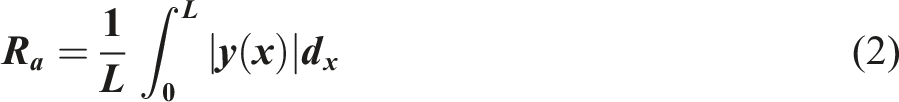
To ensure measurement reliability and repeatability, all drilling experiments were repeated under identical machining conditions. The thrust force and delamination factor values reported in this study represent the average of the repeated measurements. Variations observed in the experimental results are mainly attributed to inherent material heterogeneity of the composite laminates and minor fluctuations in the drilling process. The applied measurement procedures and data acquisition system provided sufficient resolution to capture relative differences between machining parameters and tool materials, ensuring the robustness of the comparative analysis.
Results and discussion
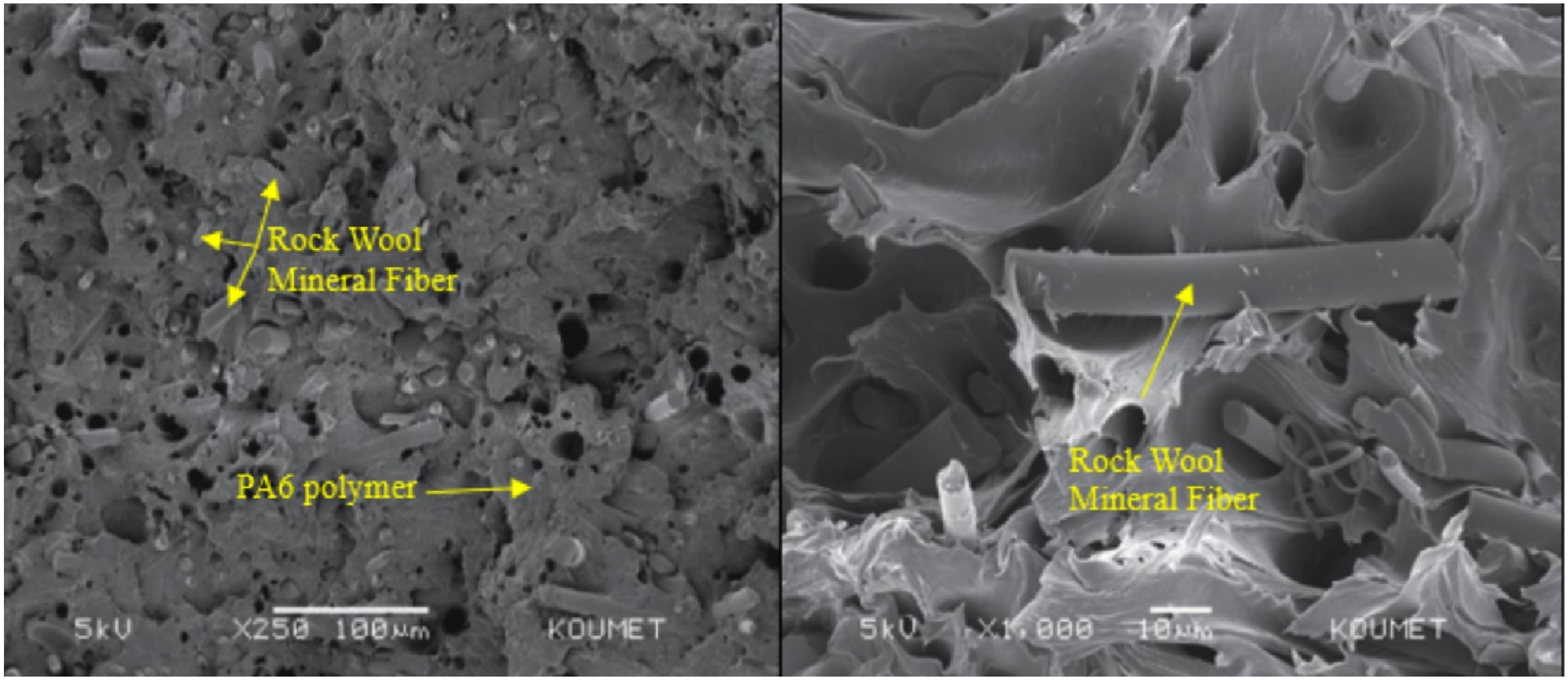
SEM images of the fracture surface of PA6 polymer composite material reinforced with 30% rock wool mineral fibers are shown in Figure 3. From Figure 3, it can be seen that rock wool mineral fibers are integrated with PA6 polymer and have enhanced interaction. SEM images of the fracture surface of PA6 polymer composite material reinforced with 30% rock wool mineral fiber.
24
The drillability behavior of PA6 polymer composite material reinforced with 30% rock wool mineral fiber was evaluated in terms of delamination factor, surface roughness and average thrust force.
Delamination factor
This research examined the impact of various drilling speeds on delamination, with the results depicted in Figures 4 and 5. When Figure 4 is examined in detail, it is observed that the delamination factor decreases with increasing feed rate. This situation can be explained in many reasons. The decrease in delamination factor with an increase in feed rate can be attributed to several key reasons. Firstly, higher feed rates allow the drill bit to pass through the material more quickly, reducing the cutting forces and consequently causing less stress and damage to the material layers. Secondly, the faster drilling process results in less heating of the drill bit and material, minimizing thermal expansion and contraction, which reduces the risk of delamination. Additionally, higher feed rates mean that the drill bit spends less time on the cutting surface, leading to smoother and cleaner cuts, thereby reducing the likelihood of layer separation. Finally, increased feed rates enhance the stability of the drill bit within the material, reducing vibrations and further lowering the risk of delamination.25–27 Effect of feed rate on delamination factor (a) 15 m/min; (b) 20 m/min; (c) 25 m/min cutting velocity. Effect of cutting speed on delamination factor (a) 0.05 mm/rev; (b) 0.10 mm/rev; (c) 0.05 mm/rev feed rate.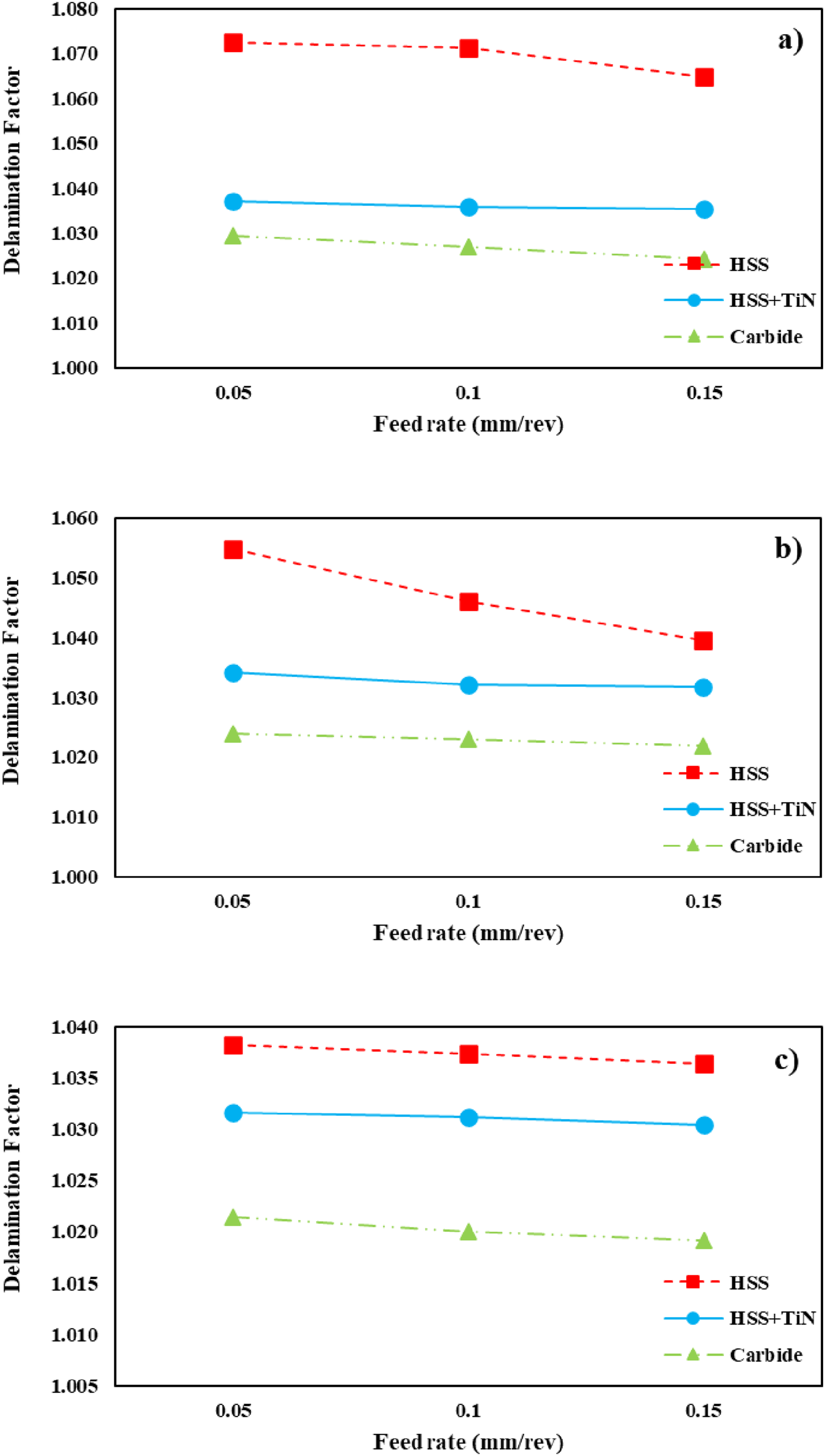
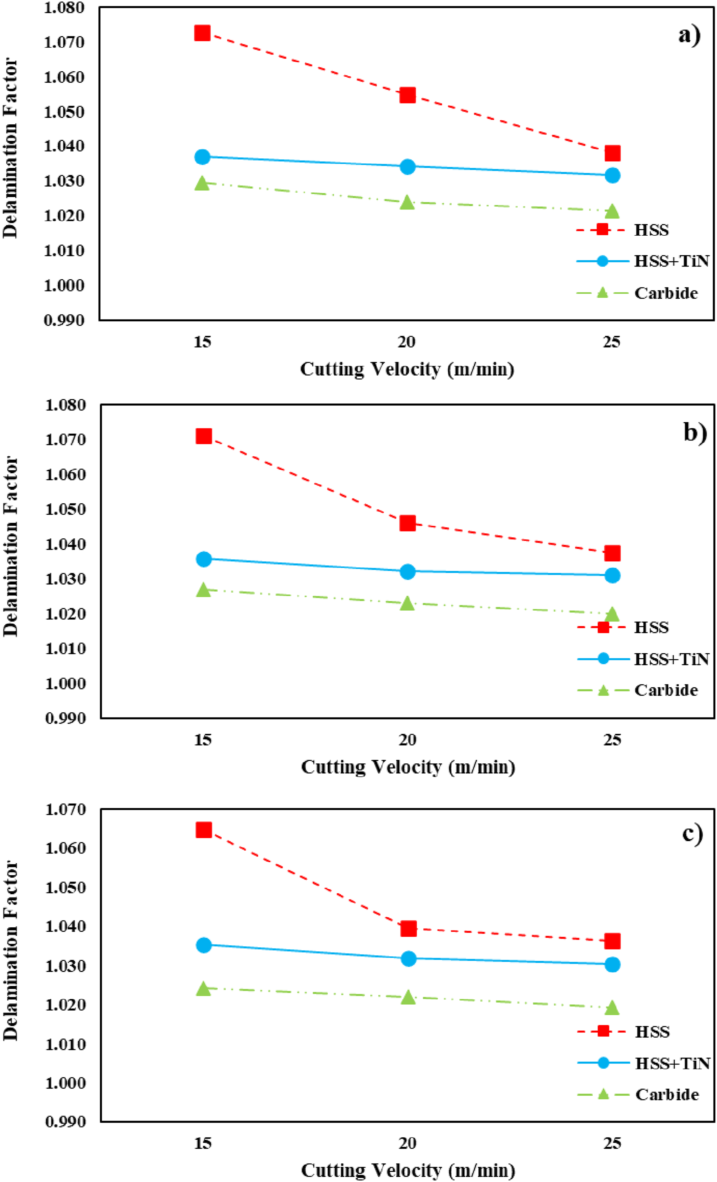
Figure 5 shows that the delamination factor decreases with increasing cutting speed. There could be many reasons for this situation. Firstly, higher cutting speeds allow the drill bit to cut through the material more rapidly. This results in smoother and more consistent cutting forces, which in turn reduce the stress on the material and lower the risk of delamination. Secondly, high cutting speeds shorten the duration of the drilling process, thereby decreasing the thermal load transferred between the drill bit and the material. Reduced thermal expansion and contraction of the material help in minimizing the risk of delamination. Moreover, higher cutting speeds enable the drill bit to make cleaner and sharper cuts, which lead to fewer surface defects and disturbances, further reducing the likelihood of delamination. Additionally, drill bit wear is less pronounced at high cutting speeds. This helps in maintaining the sharpness of the drill bit, ensuring more effective cutting and preventing delamination. Finally, higher cutting speeds provide greater stability during the drilling process, resulting in reduced vibrations. This stability helps in protecting the material from damage and decreases the risk of delamination.27–29 Delamination factor was 5.23 for HSS drill bit under drilling conditions of 20 m/min cutting speed and 0.1 mm/rev feed rate, while TiN coated HSS drill bit decreased by 1.31% to 5.161 and carbide drill bit decreased by 2.19% to 5.115.
Surface roughness
This study investigated how varying drilling speeds affect surface roughness, with the results illustrated in Figures 6 and 7. As illustrated in Figure 5, surface roughness rises as the feed rate increases. The increase in feed rate can lead to higher surface roughness due to several reasons. Firstly, higher feed rates cause the drill bit to remove more material. This increased material removal can leave more marks on the cutting surface, resulting in higher roughness. Secondly, as the feed rate increases, cutting forces also rise. These forces can create micro-cracks or deformations on the surface, contributing to increased roughness. Effect of feed rate on surface roughness (a) 15 m/min; (b) 20 m/min; (c) 25 m/min cutting velocity. Effect of cutting speed on surface roughness (a) 0.05 mm/rev; (b) 0.10 mm/rev; (c) 0.05 mm/rev feed rate.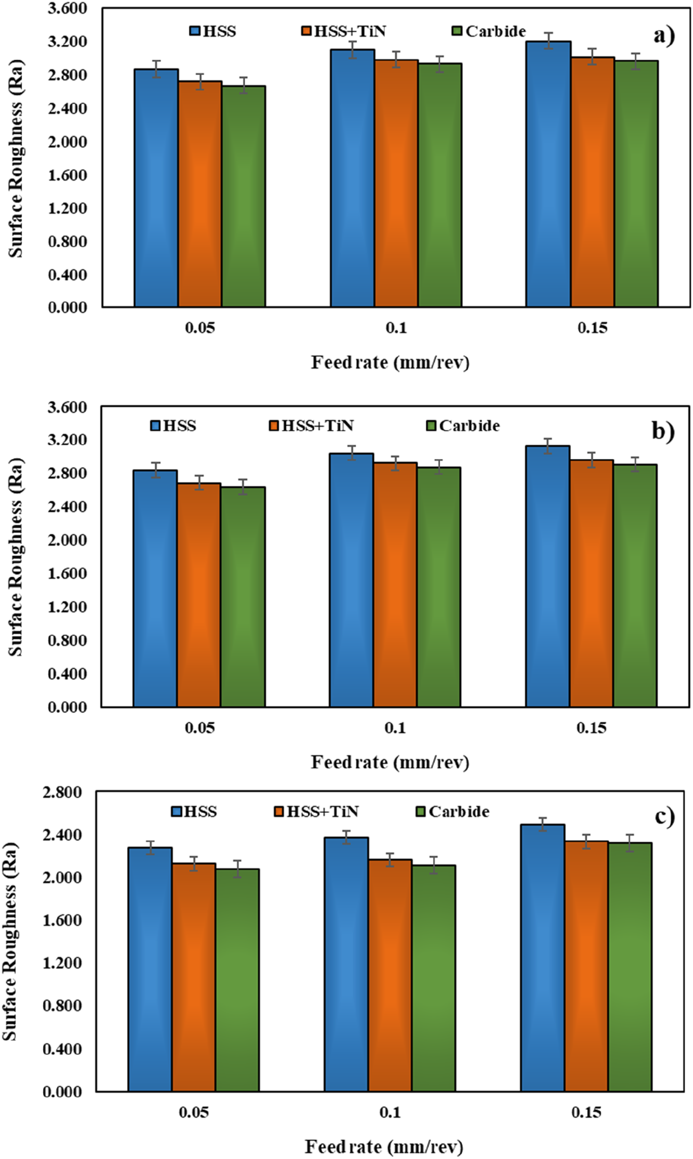
Additionally, high feed rates cause the heat generated during cutting to dissipate more rapidly. This heat can lead to thermal expansion and contraction in the material, which increases surface roughness. Furthermore, increased feed rates can result in higher vibrations and reduced stability of the drill bit. These vibrations can cause more unevenness on the surface during the drilling process, further increasing roughness. Lastly, at higher feed rates, the drill bit may wear out more quickly. A worn drill bit can leave more roughness on the surface.30–32
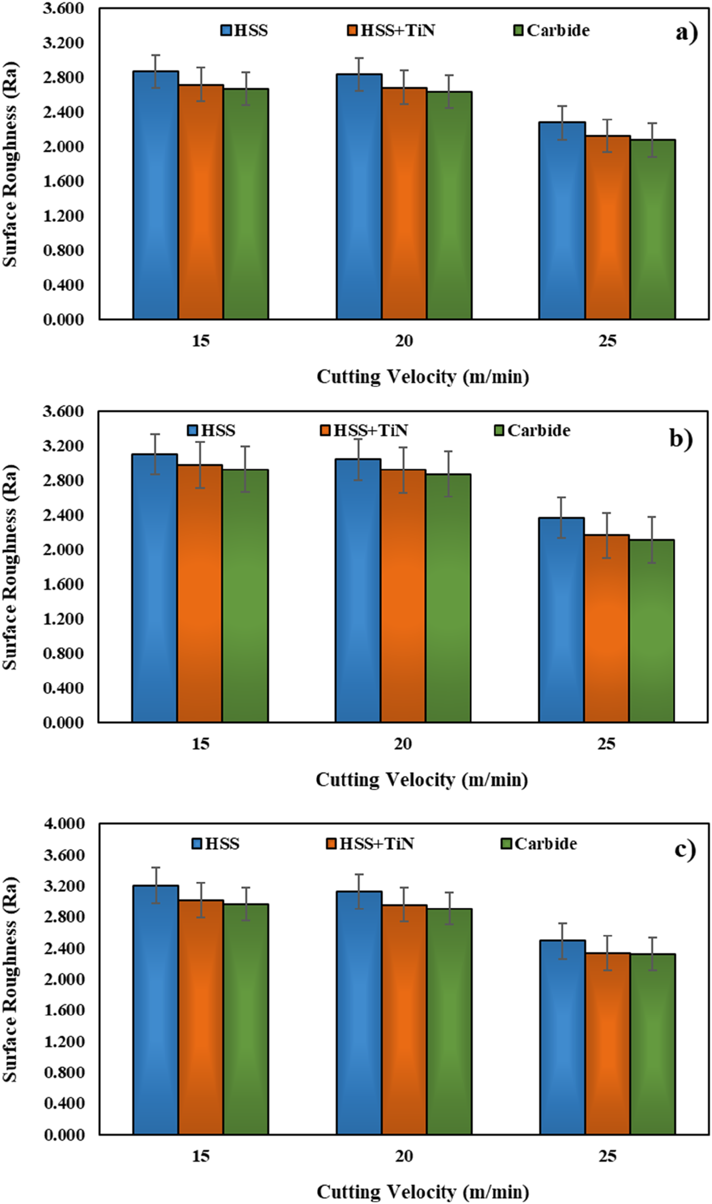
According to Figure 7, an increase in cutting velocity results in a decrease in surface roughness. The increase in cutting speed can lead to a decrease in surface roughness for several key reasons. Firstly, higher cutting speeds allow the drill bit to cut through the material more quickly and sharply. This results in a smoother and more polished surface, thereby reducing surface roughness. Additionally, higher cutting speeds enable the material to be processed more rapidly, leaving less deformation and fewer marks on the surface. This contributes to a smoother finish and lower roughness. Moreover, high cutting speeds shorten the duration of the cutting process, resulting in less heat generation. Reduced thermal effects minimize thermal expansion and contraction in the material, further decreasing surface roughness. Furthermore, higher cutting speeds improve chip removal efficiency. The rapid removal of chips prevents their accumulation on the surface, which could otherwise create roughness. Lastly, at higher cutting speeds, the drill bit wears out more slowly. This helps in maintaining the sharpness of the cutting edges, ensuring smoother cuts and reduced roughness.33–35 Surface roughness was 3.0415 for HSS drill bit under drilling conditions of 20 m/min cutting speed and 0.1 mm/rev feed rate, while TiN coated HSS drill bit decreased by 3.92% to 2.922 and carbide drill bit decreased by 5.57% to 2.872.
Average thrust force
Figure 8 illustrates the variation of average thrust force with feed rate for different drill types. The results clearly show that increasing the feed rate leads to a significant increase in thrust force under all machining conditions. This trend can be attributed to the larger amount of material removed per revolution, which increases cutting resistance and the compressive load acting on the laminate during drilling. Similar behavior has been widely reported in drilling studies of fiber-reinforced composite materials. Effect of feed rate on average thrust force (a) 15 m/min; (b) 20 m/min; (c) 25 m/min cutting velocity.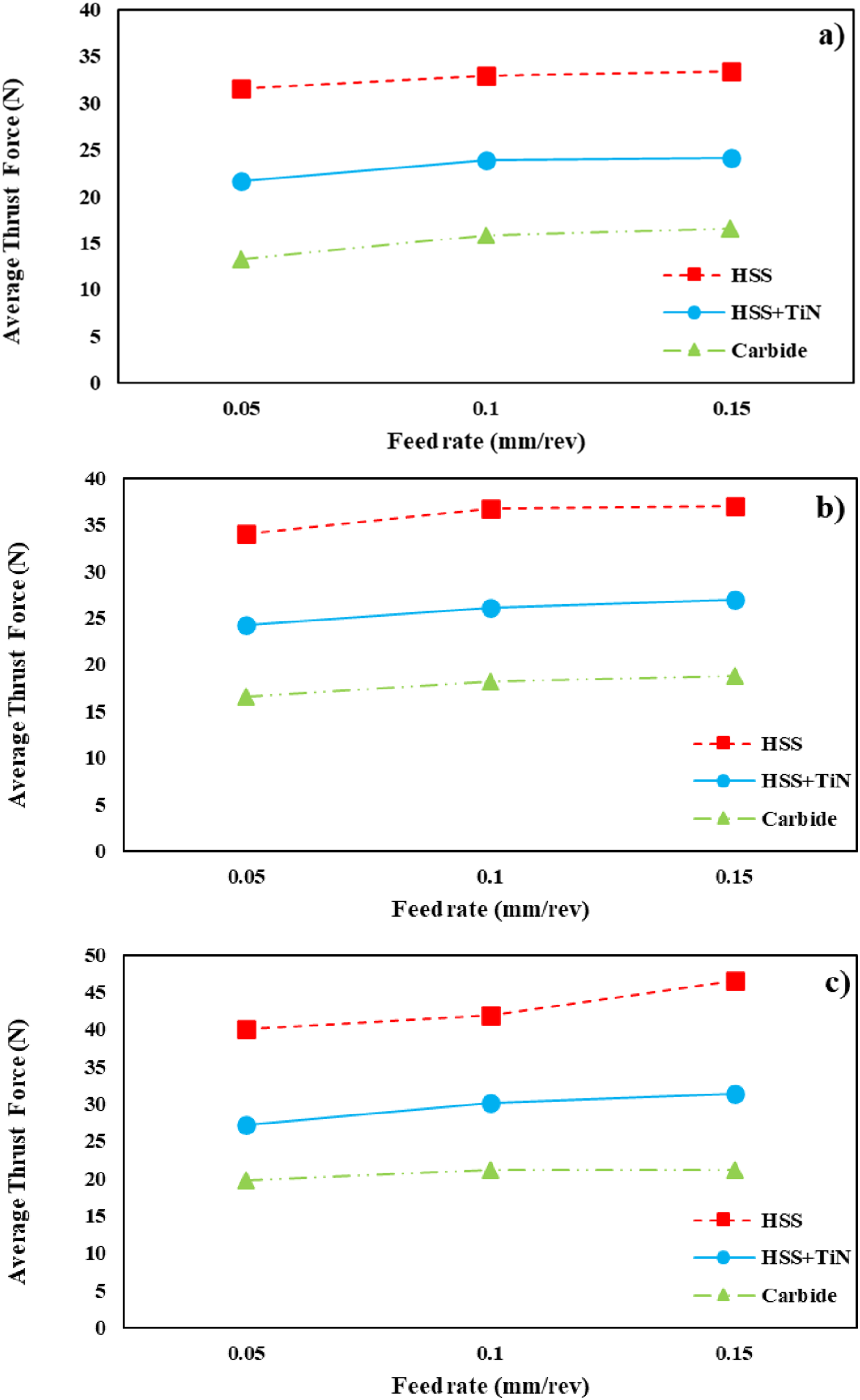
The influence of cutting speed on the average thrust force is presented in Figure 8. The results indicate that increasing the cutting speed results in higher thrust force values. This increase is mainly associated with the higher material removal rate per unit time, which leads to greater instantaneous cutting loads acting on the drill bit. As the cutting speed increases, a larger volume of material is sheared within a shorter time interval, resulting in an increase in the average thrust force.36,37
The drill bit type was found to have a pronounced effect on thrust force. Under drilling conditions of 20 m/min cutting speed and 0.1 mm/rev feed rate, the average thrust force obtained with the HSS drill bit was 36.74 N. This value decreased by 28.90% to 26.12 N when a TiN-coated HSS drill bit was used and further decreased by 50.40% to 18.22 N when a carbide drill bit was employed. These results indicate that carbide drills are more effective in reducing thrust force under the investigated machining conditions, which can be attributed to their higher stiffness and sharper cutting edges that promote a more efficient, shearing-dominated material removal mechanism.
Although both feed rate and cutting speed increase the average thrust force (Figures 8 and 9), the delamination factor was observed to decrease with increasing cutting speed (Figures 4 and 5). This behavior demonstrates that delamination is not governed solely by the magnitude of thrust force, but rather by the combined effects of force distribution, contact duration, and energy transfer at the tool–workpiece interface. In particular, higher cutting speeds significantly reduce the contact time between the drill and the laminate, thereby limiting the time available for interlaminar crack initiation and propagation at the hole exit. As a result, even though the instantaneous thrust force increases, the effective energy driving delamination is reduced. Effect of cutting speed on average thrust force (a) 0.05 mm/rev; (b) 0.10 mm/rev; (c) 0.05 mm/rev feed rate.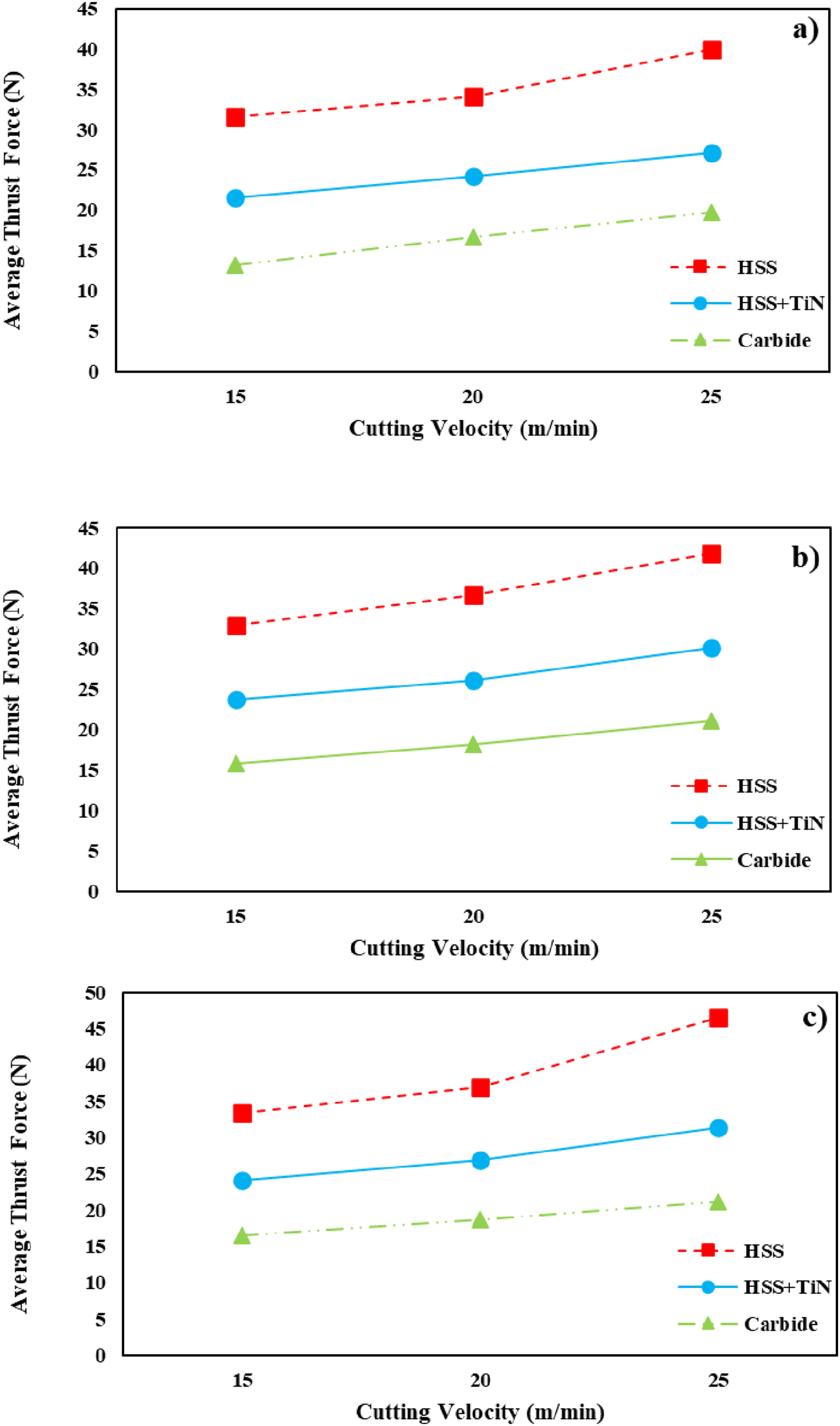
Furthermore, higher cutting speeds improve chip evacuation and promote more stable cutting conditions, which help to suppress secondary damage mechanisms such as ploughing, tool deflection, and localized stress concentration. The use of carbide drills further enhances this effect due to their sharp cutting edges and high rigidity, contributing to reduced interlaminar damage. It should be noted, however, that the present study focuses on thrust force and delamination behavior and does not include quantitative tool life indicators such as drilling length, number of holes, or wear progression. Therefore, the observed advantages of carbide drills should be interpreted as condition-specific performance improvements rather than as a comprehensive assessment of tool durability or long-term tool life.
As illustrated in Figure 9, the increase in cutting speed leads to a higher average thrust force for several reasons. Firstly, higher cutting speeds result in a greater volume of material being processed per unit of time. This means that the drill bit has to cut through more material, resulting in an increase in thrust force. Moreover, as the cutting speed increases, the temperature during the cutting process also rises. Higher temperatures can cause the material to become more adhesive, necessitating more force from the drill bit to cut through it. Additionally, with increased cutting speed, the cutting resistance of the material also increases. The material offers more resistance to the faster-moving drill bit, leading to a higher thrust force. Furthermore, higher cutting speeds can lead to increased vibration and reduced stability of the drill bit. This increased vibration requires the drill bit to apply more force during the cutting process. Lastly, at higher cutting speeds, the drill bit may wear out more quickly. A worn drill bit has to apply more force to cut through the material effectively.38,39 The average thrust force was 36.74 for HSS drill bit under drilling conditions of 20 m/min cutting speed and 0.1 mm/rev feed rate, while the TiN coated HSS drill bit decreased by 28.90% to 26.12 and the carbide drill bit decreased by 50.40% to 18.22.
Statistical results
A full factorial design was applied to evaluate the effects of feed rate, cutting velocity, and drill type, with all parameter combinations tested through repeated and randomized trials to ensure reliability. Statistical analysis using ANOVA quantified the significance of factors and interactions, while standard deviations, confidence intervals, and error bars (Figures 9 and 10) illustrated variability. Results confirmed drill type and cutting velocity as statistically significant (p < .05), whereas feed rate had a weaker effect. Regression models (Equations (3)–(5)) with values between 80.05% and 97.11% further validated these findings, demonstrating the robustness and predictive strength of the study. Main effect plots showing the influence of feed rate, cutting velocity, and drill type on delamination factor (a), surface roughness (b), and average thrust force (c).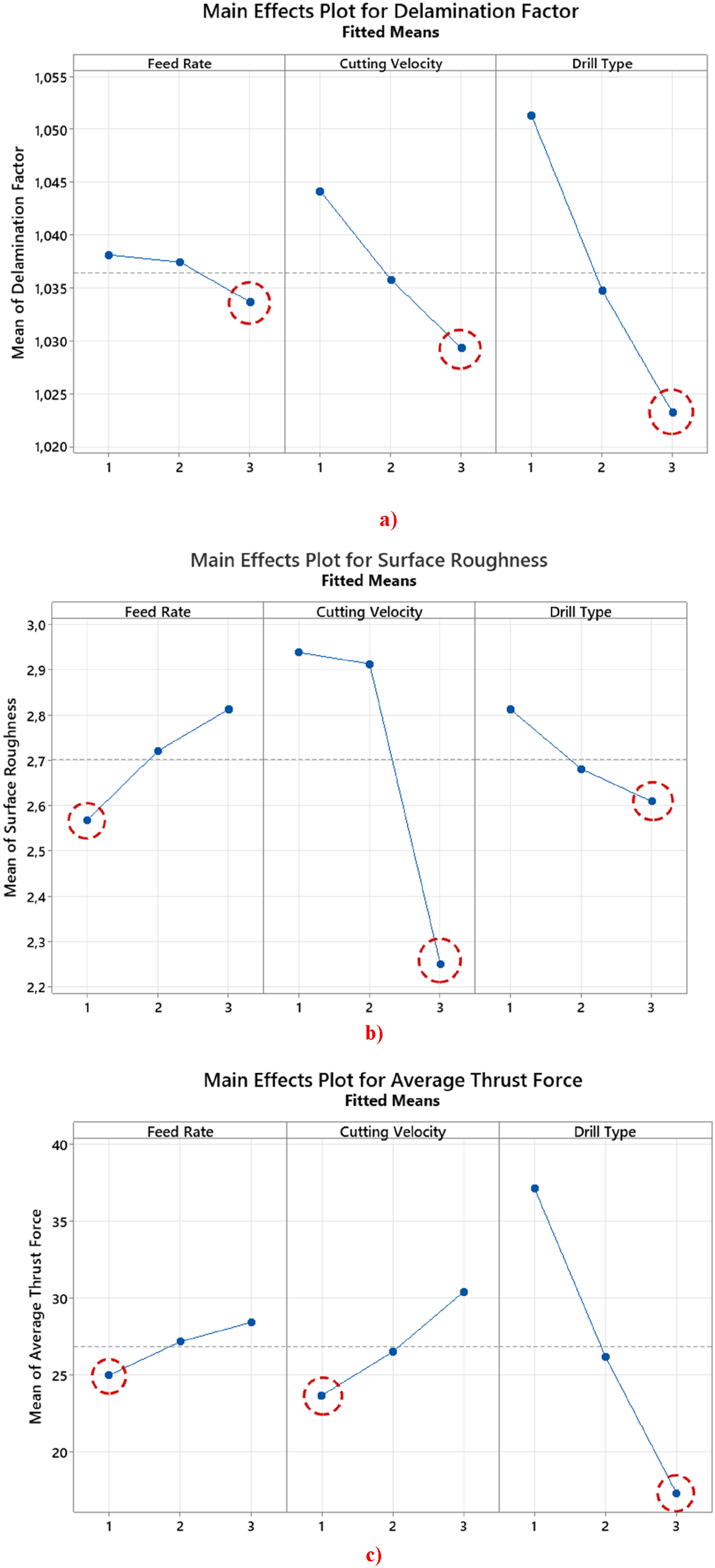
Analysis of variance (ANOVA)
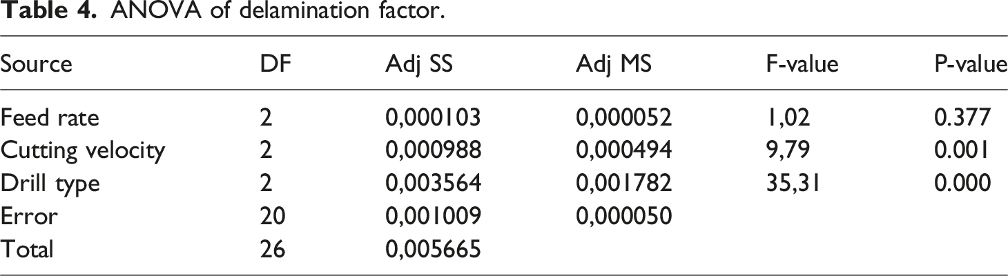
ANOVA of delamination factor.
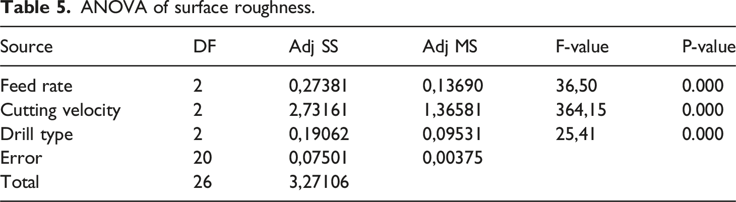
ANOVA of surface roughness.
ANOVA of average thrust force.
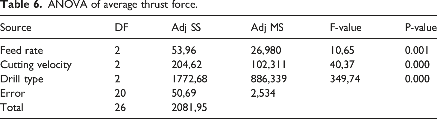
Table 4 presents the ANOVA results for delamination factor, where drill type and cutting velocity showed significant effects (p < .01), while feed rate was statistically insignificant (p = .377).
Table 5 shows the ANOVA results for surface roughness, indicating that all three parameters—feed rate, cutting velocity, and drill type—had statistically significant effects (p < .001), with cutting velocity being the most dominant.
Table 6 summarizes the ANOVA results for average thrust force, where drill type exhibited the highest F-value (349.74) and statistical significance (p < .001), followed by cutting velocity and feed rate. These results confirm that drill type and cutting velocity are the dominant factors influencing all three responses, while feed rate plays a secondary role.
Main effect plots
The main effect plots are presented in Figure 10(a)–(c), showing the individual influence of feed rate, cutting velocity, and drill type on the measured responses.
As illustrated in Figure 9(a), the delamination factor decreases slightly with increasing feed rate, more noticeably with cutting velocity, and most significantly with drill type. Carbide drills yielded the lowest delamination values, confirming their superior performance in minimizing damage.
In Figure 9(b), surface roughness is shown to increase with feed rate, while cutting velocity and drill type both reduce roughness. Higher cutting speeds result in smoother surfaces, and carbide drills consistently produced the lowest roughness values, highlighting the dominant role of cutting velocity in surface quality.
Finally, Figure 10(c) demonstrates the effects on thrust force. Feed rate and cutting velocity both increase thrust force, consistent with higher material removal rates and cutting resistance, whereas drill type shows a strong decreasing trend. Carbide drills generated the lowest thrust force values, emphasizing their efficiency in reducing cutting resistance.
Taken together, the main effect plots (Figure 10(a)–(c)) confirm the ANOVA findings, emphasizing that drill type and cutting velocity are the most influential parameters across all responses, while feed rate plays a secondary role.
Interaction plots
The interaction plots presented in Figure 11(a)–(c) illustrate how combinations of machining parameters jointly affect the measured responses. Interaction plots showing the combined effects of feed rate, cutting velocity, and drill type on (a) delamination factor, (b) surface roughness, and (c) average thrust force.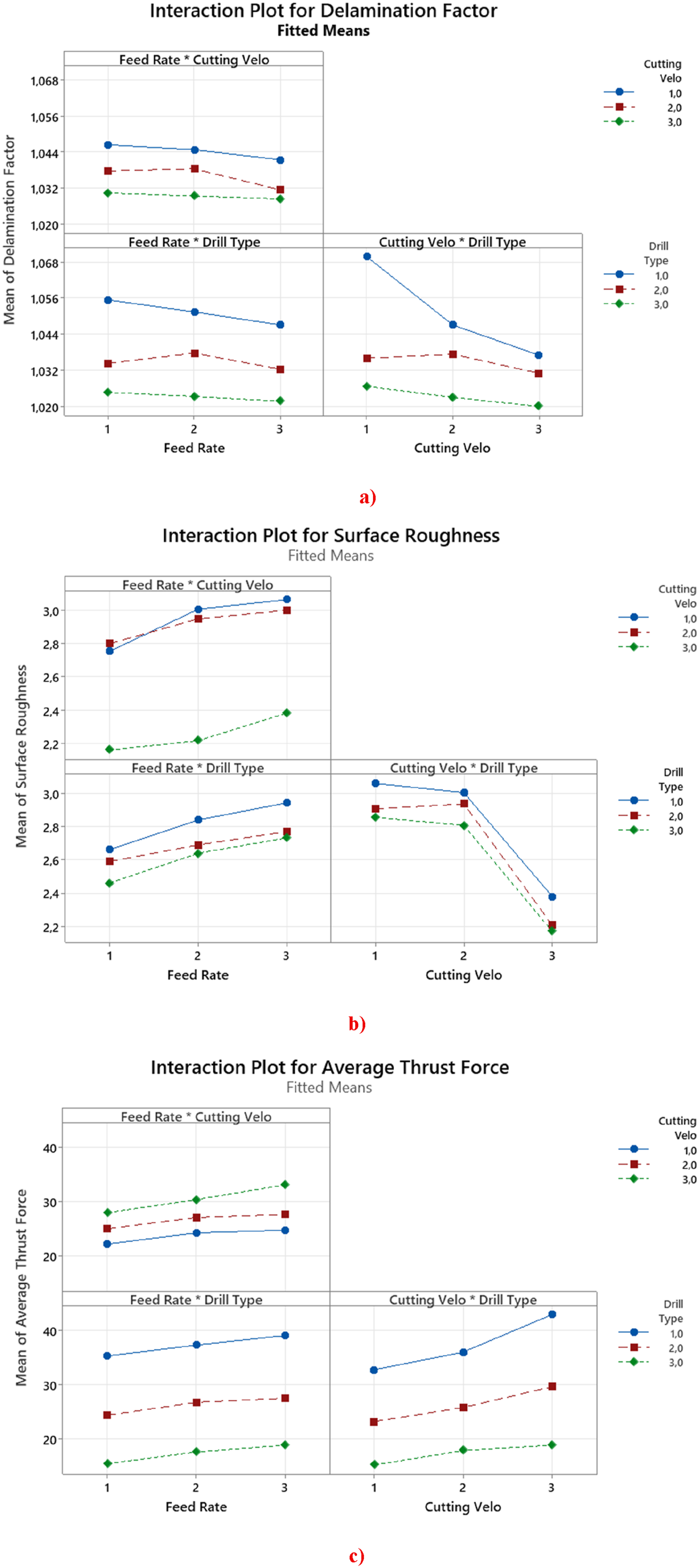
As shown in Figure 11(a), the delamination factor is most effectively reduced when high feed rates are combined with high cutting velocities and carbide drills, indicating a synergistic effect between cutting speed and tool type.
In Figure 11(b), surface roughness increases with feed rate across all drill types, but the negative impact of feed rate is amplified at lower cutting velocities. Carbide drills mitigate this effect, producing smoother surfaces even under higher feed rates.
Finally, Figure 11(c) demonstrates the combined influence on thrust force. Feed rate and cutting velocity together increase cutting resistance, while the benefit of carbide drills becomes more pronounced at higher cutting speeds, significantly reducing thrust force compared to other drill types.
Overall, the interaction plots (Figure 11(a)–(c)) confirm that the performance of machining parameters cannot be fully understood in isolation. The combined effects, particularly between cutting velocity and drill type, play a decisive role in minimizing delamination, improving surface quality, and reducing thrust force.
Regression analysis
Regression models were developed to predict the measured responses (delamination factor, surface roughness, and average thrust force) as a function of feed rate, cutting velocity, and drill type. The fitted equations are presented below:


The coefficients of determination (R2) indicate that the regression models provide reliable predictions, particularly for thrust force with an accuracy exceeding 97%. The regression models corroborate the ANOVA results, demonstrating that drill type and cutting velocity are the primary determinants across all responses, whereas feed rate exerts only a secondary influence on delamination.
Experimental findings reveal that increasing the feed rate results in higher thrust force (equation (5), Figures 7 and 8), which is consistent with the thrust force–delamination relationship reported by Ünüvar et al., 40 Baroutaji et al., 41 and Elhadi et al. 42 However, the experimental results uniquely demonstrate that the feed rate coefficient in equation (3) is negative. This indicates that under high cutting speeds and with the use of carbide drills, the delamination factor exhibits a decreasing trend as the feed rate increases (Figure 3).
While it is conventionally accepted that higher thrust forces exacerbate delamination,33,35 the current findings suggest that this correlation weakens under specific machining conditions. This phenomenon is supported by recent literature,41–47 which indicates that in mineral-reinforced composites like rock wool-PA6, higher feed rates can shorten the contact time (exposure time) between the tool and the workpiece. This reduction in contact duration minimizes thermal accumulation in the matrix and limits the time available for interlaminar stress to cause separation. Furthermore, the high rigidity and sharp edge geometry of carbide drills enhance the shearing efficiency of rock wool fibers, effectively suppressing delamination even as mechanical thrust force increases.
Consequently, although the increase in thrust force with higher feed rates is confirmed, the ANOVA results in Tables 4 and 6 reveal that this force increment has a statistically insignificant effect (p > .05) on delamination compared to the dominant influence of tool geometry and cutting speed. Thus, the observed trend is not a contradiction but a specific outcome of the dynamic interaction between high-speed machining parameters and the reinforced matrix structure.
Optimum conditions
Based on the regression models and statistical analyses, the optimum machining conditions were identified to minimize delamination factor and surface roughness while simultaneously reducing thrust force. The analysis indicates that the most favorable performance is achieved under low feed rate, high cutting velocity, and the use of carbide drills.
Under these conditions, the delamination factor reaches its lowest values, surface roughness is significantly reduced, and thrust force is minimized due to the superior cutting efficiency of carbide tools. The combination of high cutting velocity and carbide drill type emerges as the dominant factor set, whereas feed rate exerts only a secondary influence.
Thus, the optimum machining performance is obtained at low feed rate, high cutting velocity, and with carbide drills.
Wear mechanism
During the drilling of rock-wood fiber-reinforced PA6 composites, carbide drill bits consistently exhibited superior performance over HSS and TiN-coated HSS alternatives due to their high hardness. As evidenced by SEM images (Figure 15(a)–(e)), carbide bits primarily experienced abrasive wear from the hard fibers and adhesive wear due from the soft PA6 matrix adhering to the tool surface. Importantly, unlike HSS bits which showed significant flank wear, notch wear, and fractures, and TiN-coated HSS bits prone to chipping, carbide drills demonstrated minimal chipping or fractures, solidifying their position as the preferred tool for extended tool life and optimal hole quality in this challenging composite drilling application. As shown in Figure 12, SEM images of the drill bits used in the drilling operations illustrate the differences in wear mechanisms among HSS, TiN-coated HSS, and carbide drills. SEM images of drill bits used in drilling operations (a) HSS drill, (b) TiN coated HSS drill, (c) carbide drill.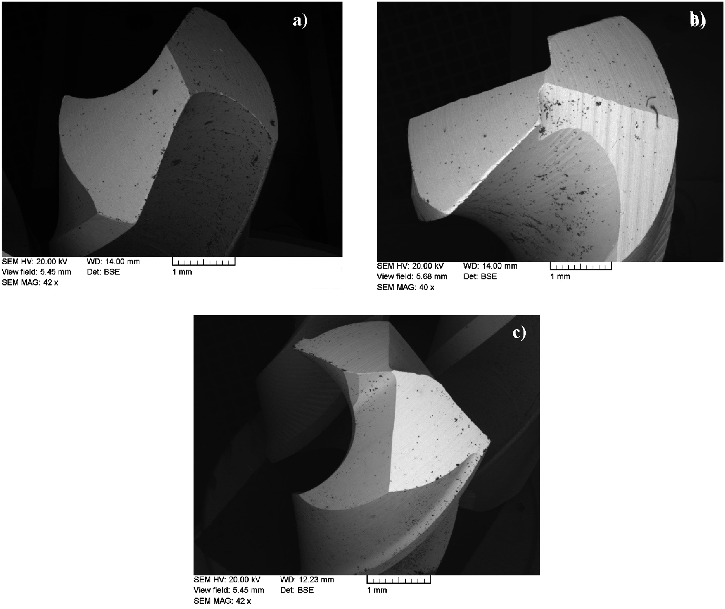
During the drilling of PA6 composite materials reinforced with 30% rock wool mineral fiber using HSS drill bits, primary wear mechanisms (Figure 13(a)–(e)) were observed. Abrasive wear is clearly evident as flank wear, abrasive marks, and edge rounding, caused by the hard rock wool fibers eroding the cutting edge. Additionally, adhesive wear occurs as PA6 polymers adhere to the drill bit due to heat generated during drilling. Fractures observed on the drill bit (Figure 15(e)) suggest mechanical fatigue/fracture due to high mechanical stresses or impacts with tough fibers. The combination of these various wear mechanisms will lead to a rapid degradation in drill bit performance, resulting in increased cutting forces, higher temperatures, and poorer hole quality. Consequently, tool life will be significantly reduced, necessitating frequent tool changes. SEM images of HSS drill bit at 0.15 mm/rev feed rate and 25 m/min cutting speed condition.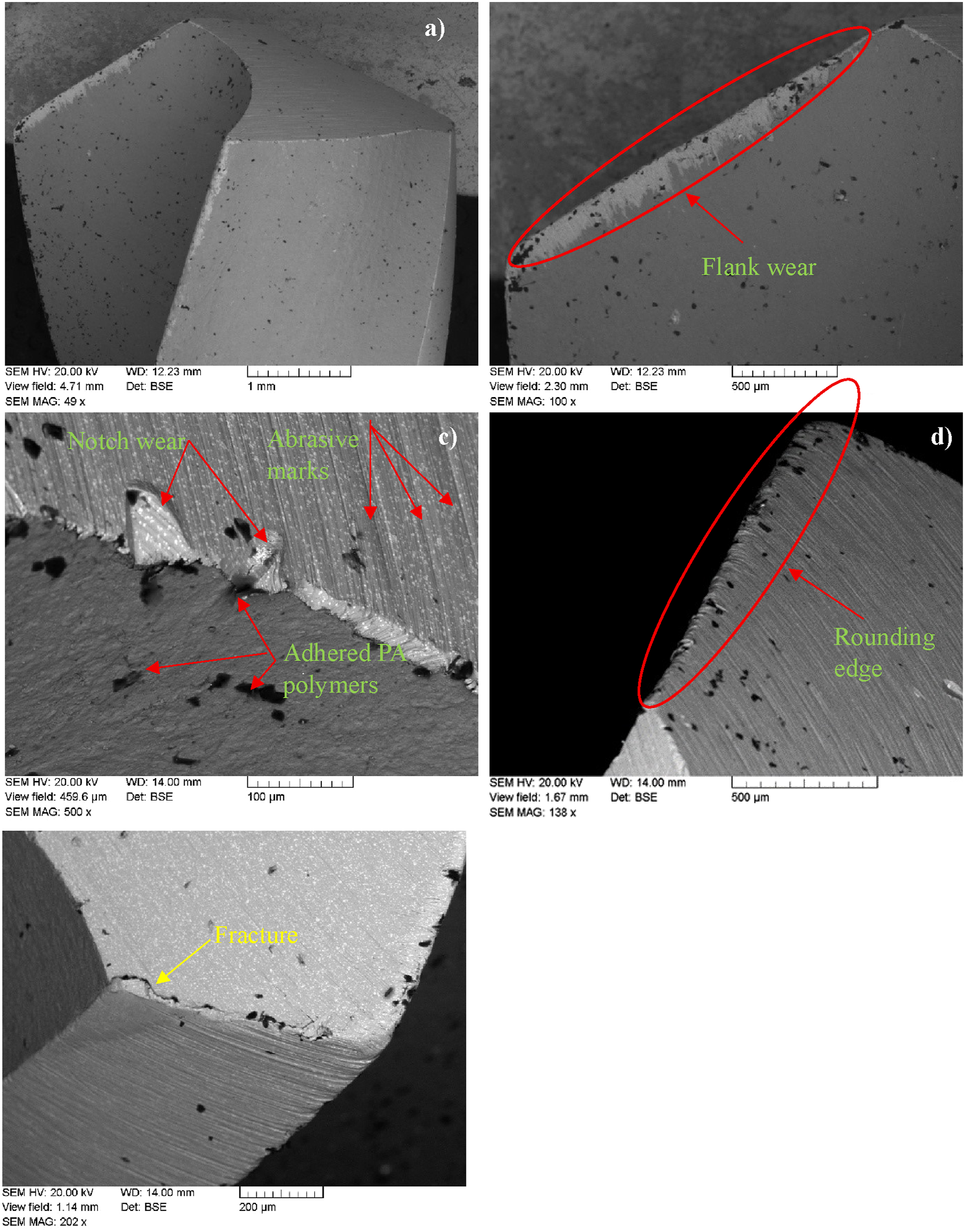
A range of wear mechanisms were observed in Figure 14 during the drilling of PA6 composites reinforced with 30% rock wool mineral fiber using TiN-coated HSS drill bits. As seen in Figure 14(c), edge rounding and abrasive marks formed due to the abrasive action of rock wool fibers, while adhesive wear occurred as PA6 polymers adhered to the drill bit, as shown in Figure 14(b). Chipping observed on the cutting edges, indicated in Figure 14(e), is indicative of both mechanical impacts and the brittle behavior of the coating or substrate. Furthermore, the formation of a shiny edge in Figure 14(d) highlights the high thermal effects during the drilling process. These combined wear mechanisms, despite the protective effect of the TiN coating, degrade tool performance, shorten tool life, and necessitate frequent tool changes. SEM images of TiN coated HSS drill bit at 0.15 mm/rev feed rate and 25 m/min cutting speed condition.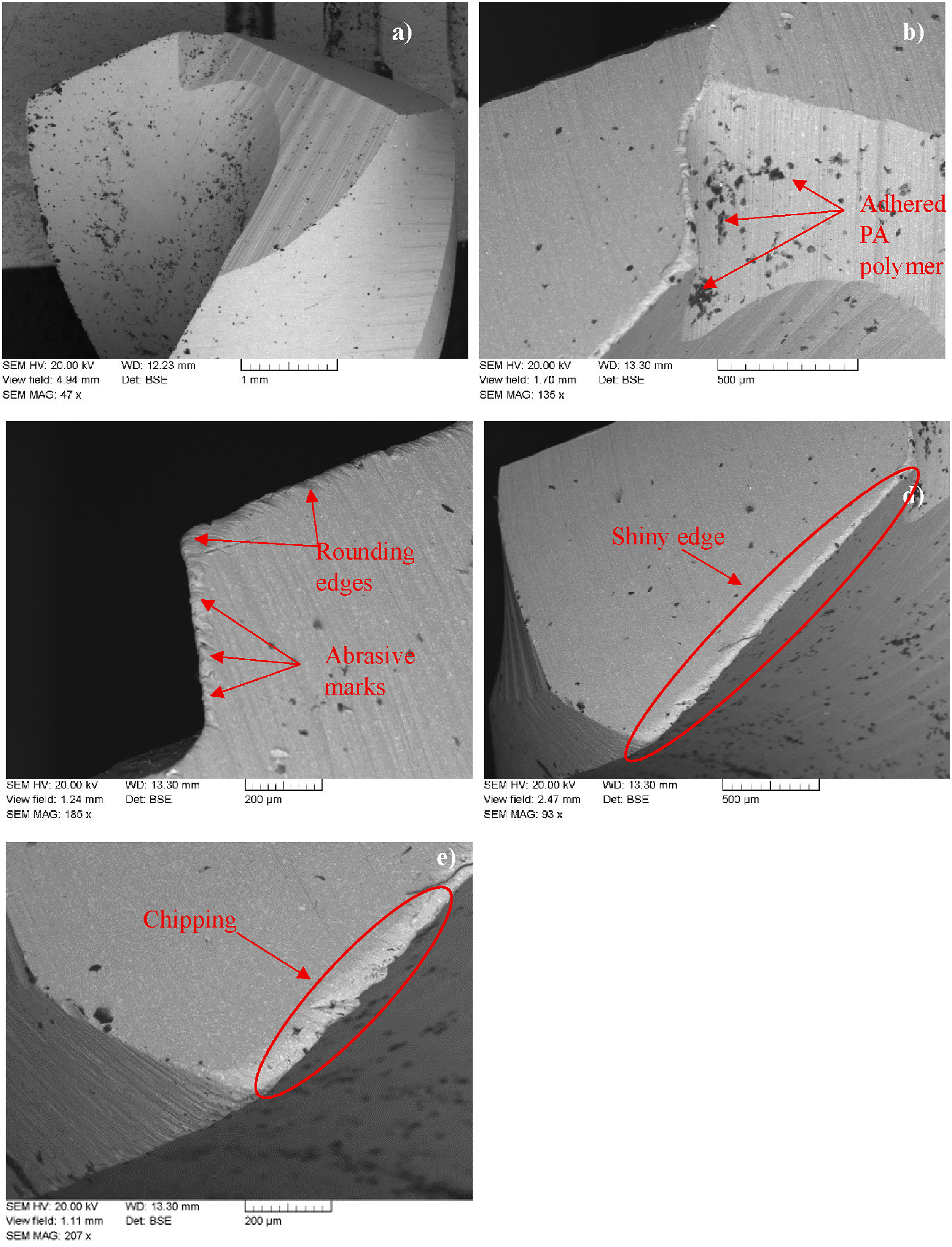
During the drilling of rock-wood fiber-reinforced PA6 composites, carbide drill bits consistently exhibited superior performance over HSS and TiN-coated HSS alternatives due to their high hardness. As evidenced by SEM images (Figure 15(a)–(e)), carbide bits primarily experienced abrasive wear from the hard fibers and adhesive wear due from the soft PA6 matrix adhering to the tool surface. Importantly, unlike HSS bits which showed significant flank wear, notch wear, and fractures, and TiN-coated HSS bits prone to chipping, carbide drills demonstrated minimal chipping or fractures, solidifying their position as the preferred tool for extended tool life and optimal hole quality in this challenging composite drilling application. SEM images of carbide drill bit at 0.15 mm/rev feed rate and 25 m/min cutting speed condition.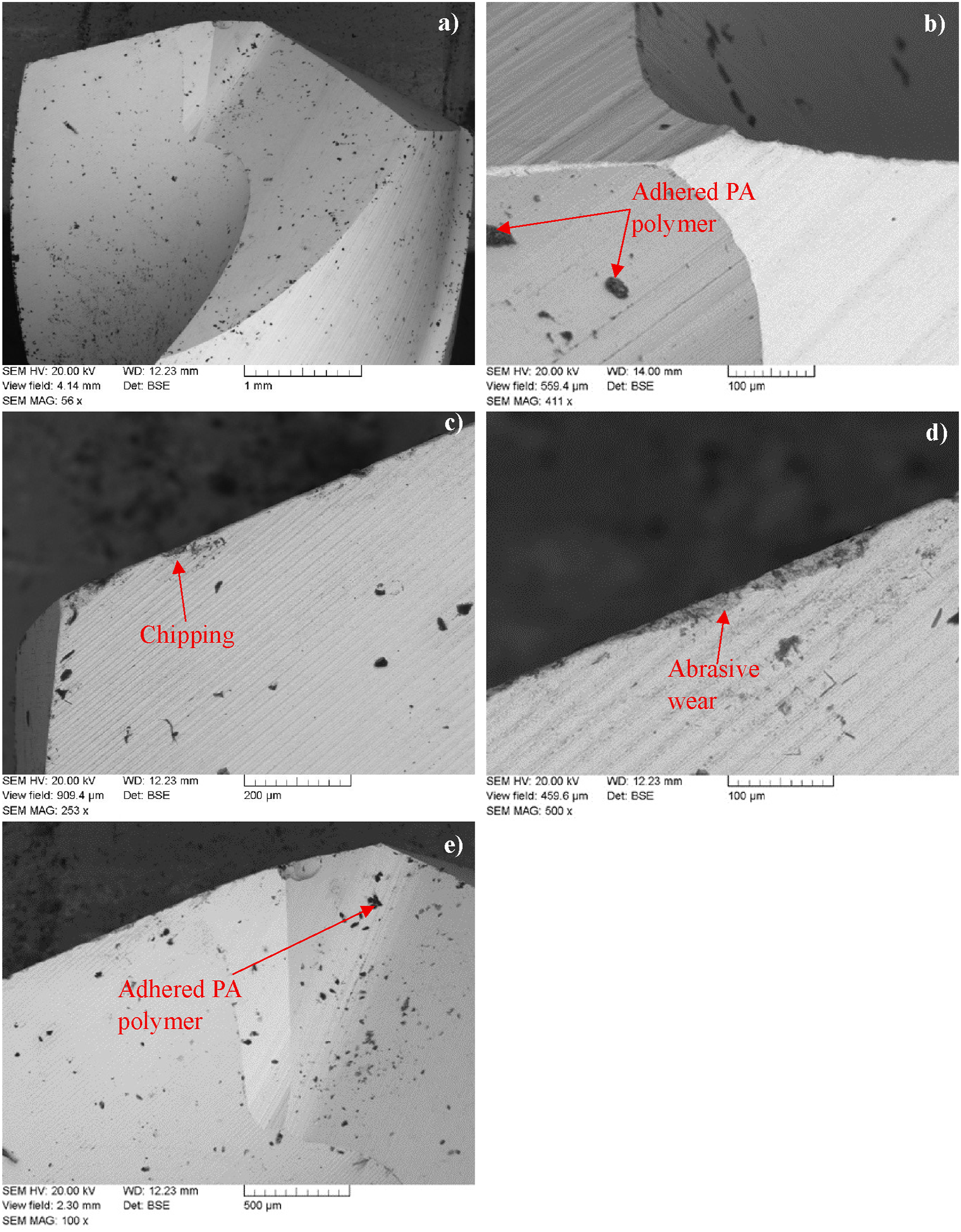
HSS drill bits easily showed flank wear, notch wear, and fractures due to their low hardness and susceptibility to abrasion, while TiN-coated HSS bits offered improved abrasive resistance but exhibited a tendency for chipping. In contrast, Carbide drill bits demonstrated the best performance against abrasive marks caused by rock wool fibers, thanks to their superior hardness, with no significant chipping or fractures observed. Adhesion of PA polymers was noted on all three materials. Considering these comparisons, and the abrasive nature and mechanical stresses of the composite material, the Carbide drill bit is clearly the preferred option for tool life and hole quality. Carbide’s high durability ensures a more stable cutting performance in this challenging drilling application.
It should be noted that the tool wear evaluation in this study is based on qualitative SEM observations of the cutting edges. While these images provide a preliminary understanding of mechanisms such as micro-chipping and edge rounding, quantitative metrics like flank wear width (VB) or crater depth were not measured. Therefore, these observations serve to illustrate how initial tool degradation correlates with hole quality, while systematic wear rate analysis remains a subject for future research.
Conclusion
The drilling performance of PA6 polymer composite reinforced with 30% rock wool fiber was evaluated under varying feed rates and cutting speeds. The results indicated that higher cutting speeds and tool types were the primary factors in controlling delamination. While it was observed that higher thrust forces occurred at increased feed rates, the delamination factor decreased due to reduced contact time and minimized thermal accumulation in the matrix. However, increased feed rates led to higher surface roughness values, which is attributed to greater material removal rates and vibration levels.
At 20 m/min cutting speed and 0.1 mm/rev feed rate, the HSS drill bit produced a delamination factor of 5.23, which decreased to 5.161 with TiN-coated HSS and to 5.115 with carbide bits. TiN-coated HSS bits reduced thrust force and surface roughness by 28.90% and 50.40%, respectively, compared to uncoated HSS. SEM analysis revealed that tool geometry and coating significantly affected the quality of the drilled holes.
Among the tested tools, carbide drill bits exhibited the most effective performance in terms of delamination control and hole quality under the experimental conditions. However, since quantitative wear progression data (such as VB or total drilling length) were not recorded, this assessment is primarily based on initial machining performance. Further research is recommended to provide a comprehensive evaluation of long-term tool life.
Footnotes
Declaration of conflicting interests
The authors declared no potential conflicts of interest with respect to the research, authorship, and/or publication of this article.
Funding
The authors received no financial support for the research, authorship, and/or publication of this article.