
Abstract
This paper investigates the interface between structural optimization for anisotropic materials and modern additive manufacturing methods by presenting and evaluating a workflow for the design of structures for fused filament fabrication using endless fiber-reinforced filament. The process chain consists of optimizing the material orientations and topology of the anisotropic structure simultaneously, non-planar slicing and load-oriented path planning for additive manufacturing. The design workflow is demonstrated using an academic example and validated by a more practical example including mounting regions for bolts and multiple load cases. The results expose requirements for additive manufacturing of continuously fiber-reinforced structures that have to be considered by the optimization process for narrowing the gap between optimization results and simulated performance of the manufactured parts. At the same time, the potential of the presented workflow for designing parts while taking manufacturability into account is demonstrated successfully.
Keywords
Introduction
Composite materials are widely used for lightweight construction. Especially fiber-reinforced polymers (FRP) appeal due to their high stiffness-to-weight ratio. Traditional FRP structures consist of laminates built from stacking unidirectional plies. Conventional manufacturing methods for FRP like resin transfer molding, automated winding and placement or autoclave molding strongly depend on forming dies that come with high manufacturing costs and slow response speeds. 1 Additionally, with the higher demand for composite materials, FRP structures are increasing in geometrical complexity. 1 Recent advances in the field of additive manufacturing (AM) apply continuously fiber-reinforced filaments in fused filament fabrication (FFF) processes,2–5 combining the desirable material properties of FRP and the design freedom of AM processes such as FFF without the need for expensive molds and long development cycles.
The manufacturing possibilities introduced by AM of continuous FRP require advanced design methods to fully utilize the potential of AM methods. Engineers use structural optimization to generate parts tailored to given design cases while respecting constraints with respect to, e.g., mass, strength or manufacturing restrictions. Optimization strategies range from heuristic methods (e.g., genetic algorithms) to gradient-based algorithms. Especially in the presence of many design variables, the use of gradient-based algorithms is essential for finding optimized solutions efficiently. 6 Therefore, only gradient-based optimization is considered in the following.
The traditional topology optimization as introduced by Bendsøe 7 is a robust and efficient method to optimize the material distribution of a structure within a given design space by varying a pseudo-density design variable for each element within a finite element (FE) mesh. It is widely used for isotropic materials using the SIMP method (Solid Isotropic Material with Penalization). 8 This method is not sufficient for optimizing anisotropic materials, as the material orientation is not considered. For structures subject to a single load case, the maximum principal stress directions (PSD) provide optimal anisotropic material orientations. 9 However, this approach is not generally applicable in the presence of multiple load cases and leaves potential of finding suitable orientation fields through numerical optimization.
Many optimization strategies for composites focus on the optimization of layups used in conventional, i.e. thin-walled FRP structures (see, e.g., the review by Xu et al. 10 ). For the optimization of conventional laminates, ply orientations, ply thicknesses and sometimes the number of plies are considered as design variables.11,12 Gürdal et al. 13 use gradient-based optimization to generate variable stiffness laminates by optimizing the fiber orientations within each ply, resulting in curvilinear fiber paths. The highest amount of design freedom in FRP optimization is achieved by simultaneously optimizing the material distribution similar to the aforementioned topology optimization, and layup-specific parameters, such as the material orientation within each ply as well as the number of plies at each point within the layup. A prominent method for such an optimization of laminated composite shells is the Discrete Material Optimization (DMO) introduced by Stegmann and Lund. 14 However, all of these methods are restricted to composite layups of shell structures. In consequence, volumetric and continuously fiber-reinforced structures require other approaches for structural optimization based on continuum element formulations.
To address optimization of volumetric fiber-reinforced structures, researchers have successfully combined topology optimization approaches for continuum structures with the optimization of anisotropic material orientation using either continuous or discrete candidate orientations.15,16 Papapetrou et al. 17 present an optimization method for topology and fiber paths using multiple infill algorithms, projecting fiber paths on the FE model for compliance evaluation during optimization. Jiang et al. 18 developed an approach for Continuous Fiber Angle Optimization (CFAO) similar to DMO where orientations and material layout within predefined layers are optimized considering predefined printing orientations. All of these approaches consider only in-plane variations of fiber angles. This restriction is leveraged by Qiu et al. 19 who consider multiple print planes and build up the final part from several substructures. Results have been manufactured using short carbon fibers which will not be discussed further, as this work focuses on continuous fibers. Fedulov et al., 20 Jantos et al. 21 and Schmidt et al. 22 present methods for the simultaneous optimization of 3D topology and material orientations, lifting the planar constraint of material orientations. Elaborate filter methods account for smoothly varying material orientations to minimize the compliance of example structures. While Jantos et al. 21 consider only single load case applications, Schmidt et al. 22 extend their method to multi-load case applications. For an extended overview the reader is referred to the review by Gandhi et al. 23 of topology optimization strategies for additively manufactured and continuously fiber-reinforced structures. Even though Fedulov et al. 20 show manufacturing results for an optimized design using continuous FRP, the optimization is once more restricted to planar 2D fiber orientations, as the design is manufactured using a planar FFF printer. Additionally, the printing paths are generated from the final CAD contour derived from the optimized topology and do not consider the optimized orientations directly for the printing paths.
AM methods enable the manufacturing of intricate optimized structures obtained using topology optimization. However, AM is not free of manufacturing constraints. Numerous approaches for incorporating AM constraints into structural optimization have been proposed under the assumption of isotropic material, for instance, overhang constraints or build orientation.24,25 These constraints require assumptions about the manufacturing process, which reduce the freedom of the optimization and manufacturing process at the same time. AM of FRP, or anisotropic materials in general, introduces additional manufacturing constraints to be considered by the optimization process that are explored in following sections. Wong et al. 26 discuss design methodologies as well as AM methods for continuous FRP parts. However, most of the methods discussed consider only 2D solutions repeated in build direction instead of allowing design variations in all three dimensions. For example, Luo et al. 27 optimize fiber paths in 2D limiting fiber path curvature and the formation of gaps or overlaps through optimization constraints. The 3D orientation fields showing out-of-plane orientations for continuous FRP require advanced AM methods for fabrication, as the optimal material orientations do not lie in parallel planes. 21 Furthermore, non-planar slicing methods are necessary to orient the slices along these out-of-plane directions. The most prominent method of computing the constituting layers is to obtain them as isolayers of scalar fields.3,28–31 A similar method using isolines is often applied to non-planar path planning.28,30–32
To the author’s knowledge, only few research works are available that focus on the combination of structural optimization of FRP and non-planar AM. The optimization method presented by Luo et al. 33 includes manufacturing constraints with respect to fiber curvature and fiber volume fraction, and it yields optimized topologies including non-planar and continuous fiber paths. Their continuity filter requires aligned material orientations to begin with, meaning homogeneous direction of neighboring orientations throughout the model. This prohibits local 180°-changes of material orientations at any stage during the optimization. Still, the presented method bridges the gap between optimization and manufacturing by choosing effective manufacturing constraints for generating non-planar but continuous fiber paths within the optimized topologies. Fernandes et al. 34 apply the work of Papapetrou et al. 17 to optimize 2D benchmark problems. In addition, the parts are manufactured and tested for a validation against numerical results from FE analyses. However, in order to manufacture and test the parts, the numerically optimized fiber paths had to be processed for the actual manufacturing setup in order to be manufacturable. This process involved adaption of path spacing, elimination of sharp corners as well as connecting closed paths into continuous loops.
The aforementioned publications exhibit deficits in one or multiple of the following aspects: • Simultaneous optimization of topology and material orientation • Consideration of 3D structures not restricted to planar material orientations • Non-planar slicing for AM • Path planning following optimized orientations • Continuous printing paths to effectively use continuous fiber-reinforced filaments • Numerical validation of printing paths
Therefore, this paper presents a complete workflow for design optimization and path planning for 3D additively manufactured fiber composite structures. The process chain is tailored to FFF using continuously fiber-reinforced filaments in contrast to existing methodologies for laminated composite layups. To analyze the impact of process-specific manufacturing restrictions on the optimized structures, the influence of different path planning approaches on the structural performance is validated numerically. The aim is to evaluate the overall process chain from the initial problem’s design space up until the printing paths ready for manufacturing.
The workflow presented in this paper is visualized in Figure 1. First, an approach for gradient-based structural optimization of continuously fiber-reinforced components is presented. The material distribution and local orientation is optimized for minimum compliance. Continuity or homogeneity of material orientations is enforced through a regularization filter. The optimization algorithm is described in the following section. Next, the non-planar slicing algorithm is presented. The aim is to slice the optimization result in a way such that fully connected printing paths match the optimized orientations as closely as possible. Following the slicing, three state-of-the-art path planning algorithms are applied to generate printing paths on the non-planar slices from the optimized designs. The slicing and path planning algorithms are presented in the following subsection. In order to estimate the quality of the printing paths, the paths are projected back on the optimization model. The compliance is reevaluated using the projected printing paths and compared to the optimized designs. The approach for this validation process is discussed in the last subsection of the Methodology section. The complete workflow is applied to two examples in the third section. The first example is a rather academic test case for presenting the methodology. The second example introduces practical considerations into the structural design process. Limits as well as potentials and aspects for further research of the current workflow are discussed on the basis of the given examples. The findings are summarized in the last section. Visualization of the workflow for design and numerical analysis of additively manufactured FRP structures.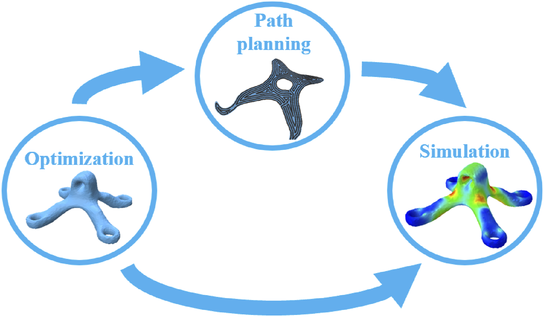
Methodology
The following sections present the individual methods applied for the workflow. Specifically, the first subsection presents the approach to structural optimization, the next subsection presents the slicing and path planning algorithms, and the last subsection discusses the approach for numerically validating the printing paths.
Structural optimization
This section describes the optimization procedure for designing the volumetric parts. To ensure the most freedom for the following load-oriented slicing and path planning, an approach similar to the one presented by Schmidt et al. 22 is implemented. This method optimizes the material orientation within each element without any restrictions with respect to the direction or the following slicing process. The method is outlined in the following.
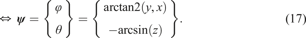
The basis for the optimization is a finite element model of a given design space Ω. The objective of the optimization procedure is to find a material distribution and orientation field within Ω being as stiff as possible. For that, a gradient-based topology optimization is combined with a simultaneous optimization of the material orientations on element level. This is achieved mathematically by minimizing the compliance c or the sum of compliances c
i
for n
LC
load cases. The optimization problem is described by Rotation angles for the transversely isotropic material.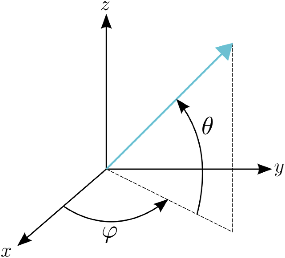


Initial design
Structural optimization yields designs that have to be considered as locally optimal designs. The outcome of each optimization depends, among other things, on the initial design, i.e., the initial design variables. A common practice for topology optimization subject to a volume constraint (3) is to use the volume fraction Vcon as the initial value for all density design variables. This approach is followed for all examples in this study. The maximum principal stress directions (PSD) are considered as the initial orientation field for the following topology and orientation optimizations. In the presence of multiple load cases, multiple PSD exist, and the optimal material orientation is not trivially found. In this case the initial orientation field is prescribed as the PSD for the dominating load case that yields the highest compliance for the initial design.
Regularization filter
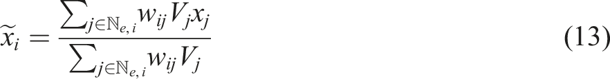
A regularization filter is applied to all variables in order to avoid mesh-dependency of the solution and checkerboard patterns of the density distribution, as well as smoothing the orientation field for improved continuity of the optimized material orientations.8,22 A common filter method is a weighted average on the design variables35,36 around the center of each element within a given radius r. The filter operator is given for the generalized filtered variable

Alternatively, the filter operation can be formulated implicitly as the solution of the Helmholtz-type differential equation
37
:

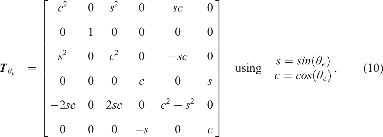
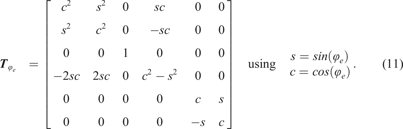
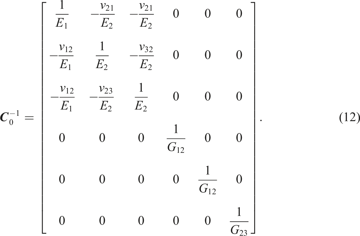
In this work, the PDE filter is used for the density variables only. Filtering the orientation variables using the same PDE-based approach poses two problems: Firstly, the orientation angles are periodic by factors of 2π = 360°. Secondly, the effective stiffness properties are identical for rotations of π for a transversely isotropic material. Therefore, the constitutive matrix
Although additional filters for additive manufacturing exist to account for manufacturing restrictions within isotropic topology optimization, the method presented in this work does not include any additional filtering in order to reduce the number of assumptions made in advance regarding the manufacturing process. While the presented filter restricts the curvature of the orientation field, gaps and overlaps depend on the actual fiber paths on printing surfaces, both of which are not determined in the optimization stage. Therefore, the presented optimization and path planning workflow does not address the formation of gaps and/or overlaps during the optimization. This leaves more freedom for the optimization process as well as the following slicing and path planning.
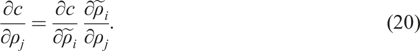
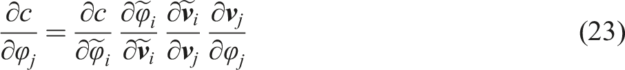
Gradients for the optimization
The optimization uses the gradient-based Method of Moving Asymptotes (MMA) algorithm
40
for solving the optimization problem. The gradient for the compliance with respect to the filtered density variables is given by


Result transfer
As the optimized density fields contain intermediate values between 0 and 1, the optimized density and orientation fields are interpreted for the AM processing. An isosurface is extracted from the density field
The orientations Illustration of the workflow for extracting a tetrahedral mesh from the optimization mesh that is then used for evaluating the structural performance of the optimized designs as well as the projected printing paths.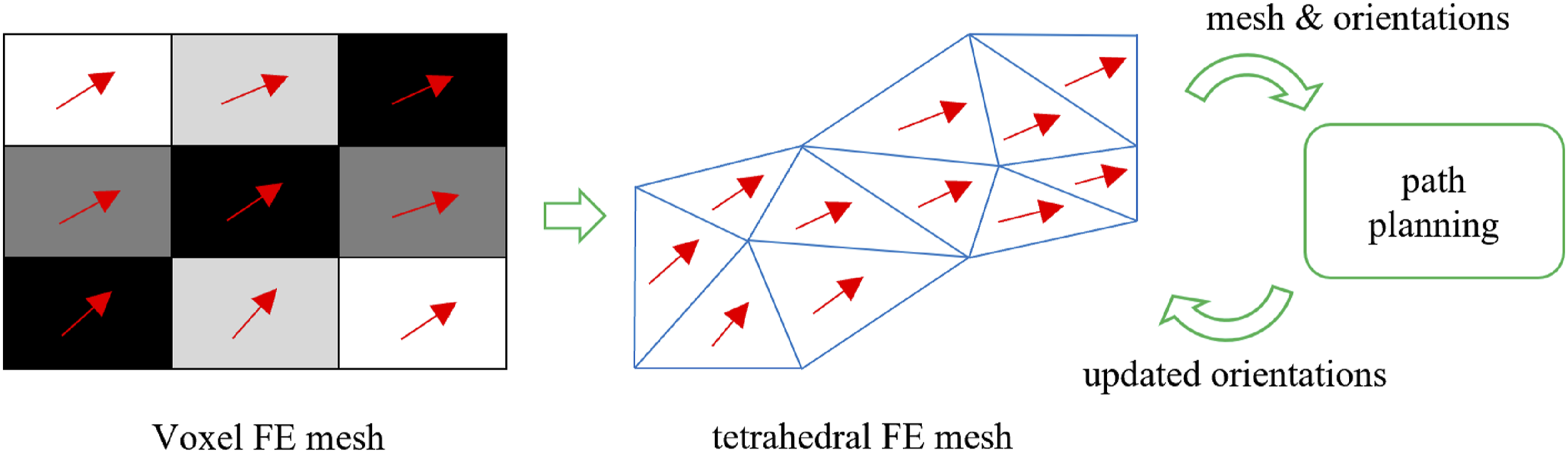
Additive Manufacturing Preprocessor
The solid tetrahedral mesh
In order to enable the actual manufacturing on a multi-axis printing machine, the optimization results have to be converted into machine instructions. These instructions consist of movement and extrusion commands which result in the desired part geometry and composition. This resulting part should implement the optimization results as closely as possible, while still considering the following process-induced requirements and limitations: 1. Material deposition: Extruded material can only be deposited onto the print surface or existing material. 2. Low void content: Voids are not completely avoidable in the FFF process, yet should be kept to a minimum for adequate part quality. 3. Absence of self-intersection: The nozzle’s path should not intersect itself to avoid nozzle clogging and uncontrolled material deposition. 4. High surface quality and dimensional accuracy. 5. Minimal waste material: Material waste created by purging or excess material deposition should be kept to a minimum. 6. Collision avoidance: Neither should the printing system collide with itself, nor should the nozzle collide with the already deposited material when executing the manufacturing instructions. A collision of the nozzle and printing surface is also disallowed.
Slicing
The optimization results
The deposition has to start with a planar layer on the flat printing surface to meet requirement 1. To still be able to create non-planar slices, the layer height of each slice is locally varied to incrementally adapt the surface to the desired alignment with
The field
To remove these few remaining inhomogeneities without negatively impacting the load-orientation of the field, exclusive smoothing in the inhomogeneous region is required. This is achieved by applying a weighting factor on the smoothing using the fields vorticity as an indicator for directional inhomogeneity. The weighting factor w
s
is computed as the norm of the vorticity as follows:

After these preprocessing steps, the process of computing the scalar field and slicing is performed, which has been described in detail by Kipping et al. and Fang et al.3,30,42 A short description is given in the following for completeness. The guiding field
Path planning
Having computed the slices, the next step towards the manufacturing instructions is the computation of paths within the slices. The path for a surface is typically divided into contour parallel paths to create the outer shell and satisfy requirement 4 and the infill path to cover the inner region of each surface. In this work three path planning methods are applied: The contour parallel first-in-spiral-out (FISO) method, a discrete load-oriented method (DLO) and the load-oriented and continuous Looping algorithm (LOOP). All three methods use a fixed number of outer contours and differ only in the infill method. The two most important measures here are path continuity and load orientation, which are achieved by the methods to a varying degree. As topology optimization is applied in this work which already places material where it is needed the most, 100% infill is applied in all cases and voids are to be minimized. In the first part of the following section, the generation of contours and the contour parallel FISO algorithm is presented after which the two load-oriented infill methods are discussed.
All methods first generate unconnected line segments and then connect them into a single path for each surface which may contain travel movements. The contour parallel lines are generated by computing the geodesic distance field ϕ to the surface boundary and extracting the isolines of this field. The distance field ϕ is computed by solving the eikonal equation

For the DLO infill, the unconnected line segments should be oriented along
Looping can be viewed as a combination of FISO and the DLO method. The construction of loops allows for the FISO rerouting algorithm to be applied to the load-oriented line segments resulting in a continuous path for a surface. The loop line segments are computed by extracting the isolines of the load-oriented field at double the path width, computing the geodesic distance field to these isolines and extracting the loops as isolines of the distance field.
The last step in generating the manufacturing instructions is the connection of the subpaths of each layer into a global path. In this step collisions are checked and further post-processing is applied.
In conclusion, the preprocessing steps described in this section aim at transforming the tetrahedral mesh
Feedback of printing paths for validation
After computing the printing paths for the additive manufacturing, the paths are compared to the optimized design numerically. The feedback and comparison procedure is outlined in the following section.
The printing paths resulting from the previously presented path planning algorithms are projected back onto
The extrapolated printing paths within
Numerical examples
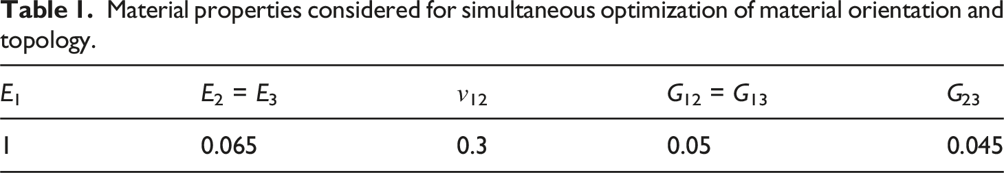
The following section presents two examples to showcase the workflow for designing and planning AM parts. All parts are optimized using a volume constraint Vcon = 0.25. The initial layer height for the path planning is chosen to 0.35 mm and the path spacing is set to 0.5 mm. The compliance of the optimized and smoothed designs is compared to the designs using the projected printing paths to estimate the influence of the path planning on the performance of the structure. The numerical study is performed as a preparation for physical tests consisting of manufacturing and testing continuously carbon fiber-reinforced structures. At the current stage of research, no material tests have been performed using the anticipated non-planar AM plant due to limited availability of the material and the specific manufacturing setup being under development. The material properties considered for the numerical examples are listed in Table 1. The ratio of stiffness properties is similar to a typical unidirectional carbon fiber-reinforced composite material.
Material properties considered for simultaneous optimization of material orientation and topology.
As discussed in the subsection on the initial design, it is questionable to justify a specific initial orientation different from random orientations or PSD. Especially for single load case problems, PSD provide a valid starting point. Without considering the simultaneous topology optimization, the PSD are probably close to a local minimum of the optimized orientations considering regularization methods for continuous orientations. During testing of the presented method, no better local minimum has been found for a given problem using initial orientations different from the PSD of the dominant load case. Therefore, PSD are considered as the most suitable initial orientation field for all following anisotropic optimizations.
For brevity, the topologies resulting from isotropic topology optimization are referred to as the TOPO design, while the designs simultaneously optimized for material orientation and topology are referred to as MOTO (Material Orientation and Topology Optimization). The printing paths are denominated FISO, DLO and LOOP corresponding to the path planning algorithm as introduced in the pevious section.
Convergence of the optimization is assumed if the change of design variables, normalized by the upper and lower bounds, or the relative change of the compliance is lower than 1 × 10⁻⁴.
X-bracket
The first structure demonstrates the workflow using a simple test case. The design space shown in Figure 4 is a rectangular cuboid having a square base of edge length 40 mm and a height of 20 mm. The structured mesh uses linear cube-shaped elements. The number of elements per direction is 60, 60 and 30 for the x-, y- and z-direction, respectively. The filter radius for all design variables is chosen to r = 2 mm. The lower corners are supported against displacement normal to the respective surfaces. The boundary conditions are applied to 7.5 % of the base edge length for every corner. An upward facing unit load is applied at the top of the structure and distributed over five percent of the upper surface. The nodes for the boundary conditions and loads are highlighted in Figure 4. The structure is referred to as X-bracket. Design space for X-bracket showing nodes for boundary conditions and loads in blue and red, respectively.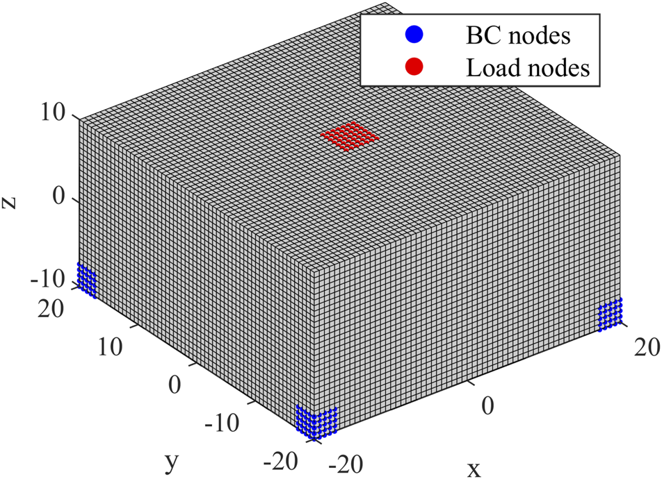
The topologies for the optimized TOPO and MOTO designs are shown in Figure 5(a) and (b), respectively. As the design case is simple and point-symmetric, so is the TOPO design. In contrast, the rotational symmetry of the MOTO design is slightly disturbed for the vertical structure connecting the upper and lower part of the design. This is a result of numerical effects during the optimization and could be avoided, if symmetry constraints were considered during the optimization. Material is removed from the legs to the lower part of the structure in comparison to the TOPO design. Smoothed tetrahedral mesh 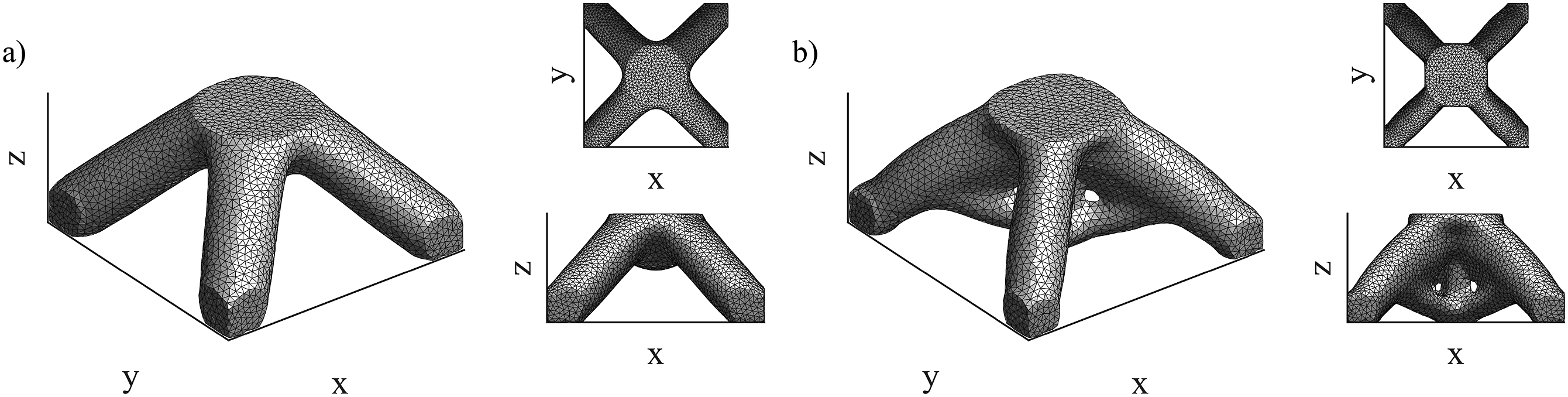
The difference of the optimized topologies shows that the consideration of additional orientation design variables greatly influences the topology optimization. Numerical studies based on different initial orientation fields for the orientation variables produced slightly different designs, however the optimized compliance was similar.
The orientations for all subsequent designs are visualized using colored line segments for each element. The absolute x, y and z components of the orientations are used as normalized RGB values for color-coding, respectively. The PSD for the TOPO design are visualized in Figure 6(a) and the optimized MOTO orientations are shown in Figure 6(b) for comparison. In both cases the orientations are aligned within the legs of the structure. The orientations connect the legs at the outer-top regions of the structure smoothly for both cases. The orientations in the center are aligned with the orientation of the load. This creates discontinuities between the leg-connecting regions around the center part of the structure and the z-aligned orientations in the middle of the structure. These discontinuities pose problems for the slicing and path planning as described in the previous section, but they are impossible to avoid in 3D-problems. Furthermore, the orientations in regions for boundary conditions and loads are not restricted to the outer surface of the structure, contradicting requirement 4 for the path planning algorithm, which demands a high surface quality, meaning contour-parallel paths for the outer surface of the part. a) PSD for TOPO design and b) optimized orientations for MOTO design of X-bracket. The components of the absolute orientation vectors are used as RGB color values for coloring.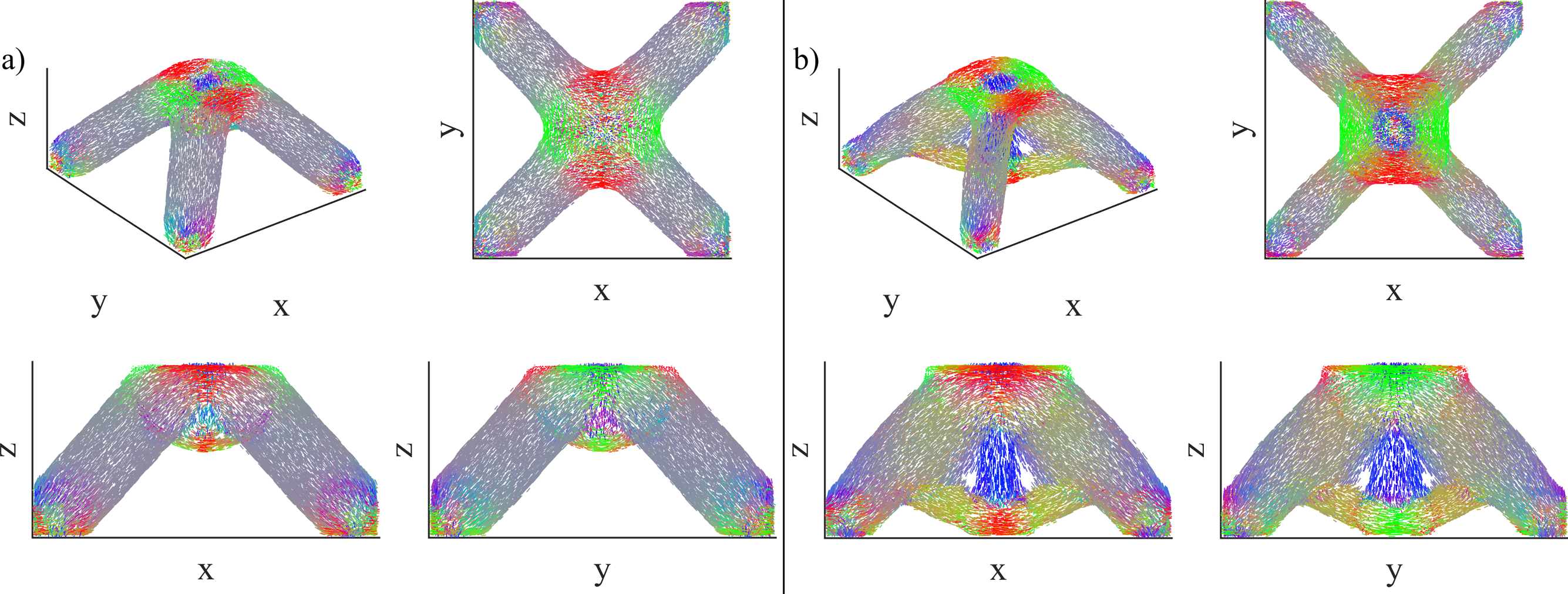
Figure 7 shows two examples of printing paths computed using the FISO and the Looping method for the TOPO and MOTO design, respectively. The remaining paths for the X-bracket are included in Figures 13 and 14 in Appendix A. The paths are visualized as tubes, however the radius does not exactly match the simulated path width for better visibility. The plots show that the symmetric property of the input direction field a) FISO paths for TOPO design and b) LOOP paths for MOTO design of X-bracket.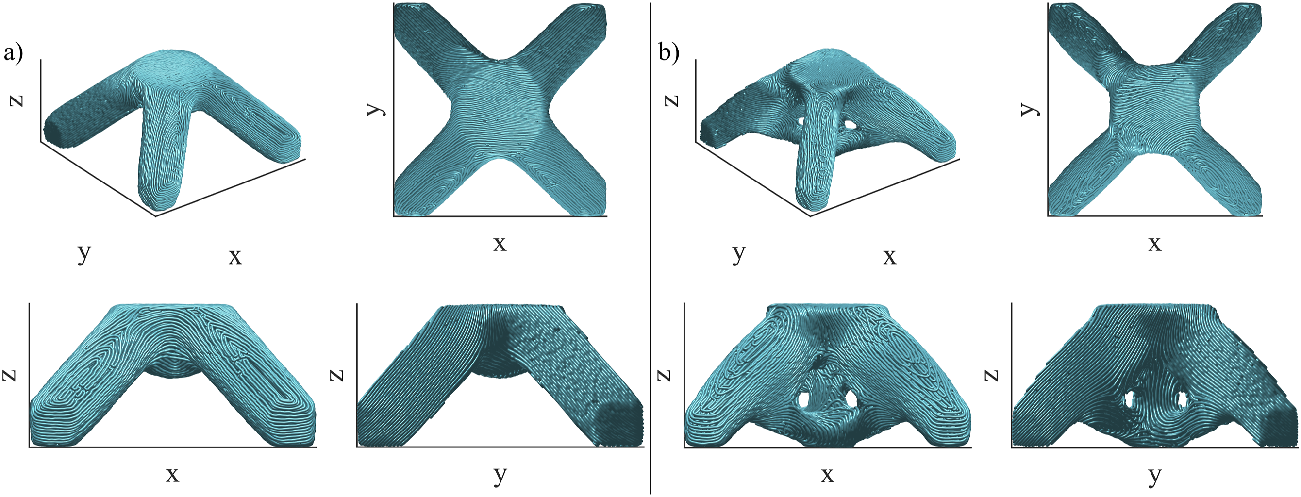
Compliance c of TOPO and MOTO designs for X-bracket using maximum principal stress directions (PSD) or optimized orientations (OPT) as well as projected printing paths for material orientations.
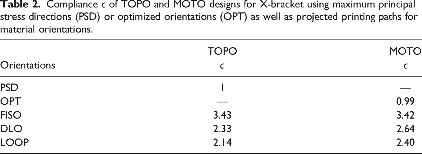
For this simple single load case example, it was anticipated that the TOPO design using PSD as material orientations and the MOTO design are of similar performance. The following example demonstrates a more practical application of the demonstrated process to extend the evaluation of the MOTO and subsequent path planning methods.
L-bracket
The second example introduces multiple load cases as well as functional regions for the application of boundary conditions and loads. The meshed design space is shown in Figure 8. The structure is referred to as L-bracket, as its design space resembles the shape of the letter L. Two holes are included in the design space for mounting the structure (top hole) and application of loads (bottom hole). Three load cases are considered: The dominating load case is a downward facing load of magnitude 1 in negative z-direction, distributed over the top surface of the bottom hole. Two additional loads of magnitude 0.1 act in positive x- and negative y-direction. The node regions for all loads and boundary conditions are indicated in Figure 9. The optimization objective is to minimize the sum of the compliance from all load cases. The filter radius for the optimization is chosen as r = 2.5 mm. Additionally, the density variables around the holes are prescribed to equal 1 in order to preserve the material at the mounting points. This non-design space is highlighted in Figure 8. Both regions contribute to the volume of the optimized structure and account for 9.11 % of the design space’s volume, leaving approximately 16 % of the material to be distributed during the optimization while fulfilling the optimization constraint of 25 %. The fiber orientations are free to change in these regions. The initial orientation field for the simultaneous optimization of material orientation and topology is the field of maximum PSD from the dominating load case within isotropic analysis of the full design space. Design space for L-bracket including highlighted non-design space for density variables where ρ
e
= 1. Nodes for a) load application in z- (left), x- (middle) and y-direction (right) and b) boundary conditions of L-bracket where nodes in red and blue are blocked against movement in z-direction, and green nodes are blocked against movement in x- and z-direction.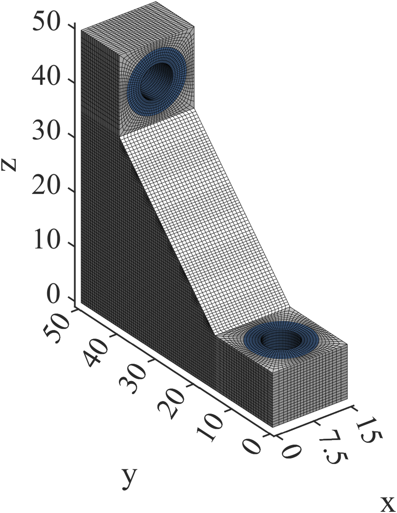
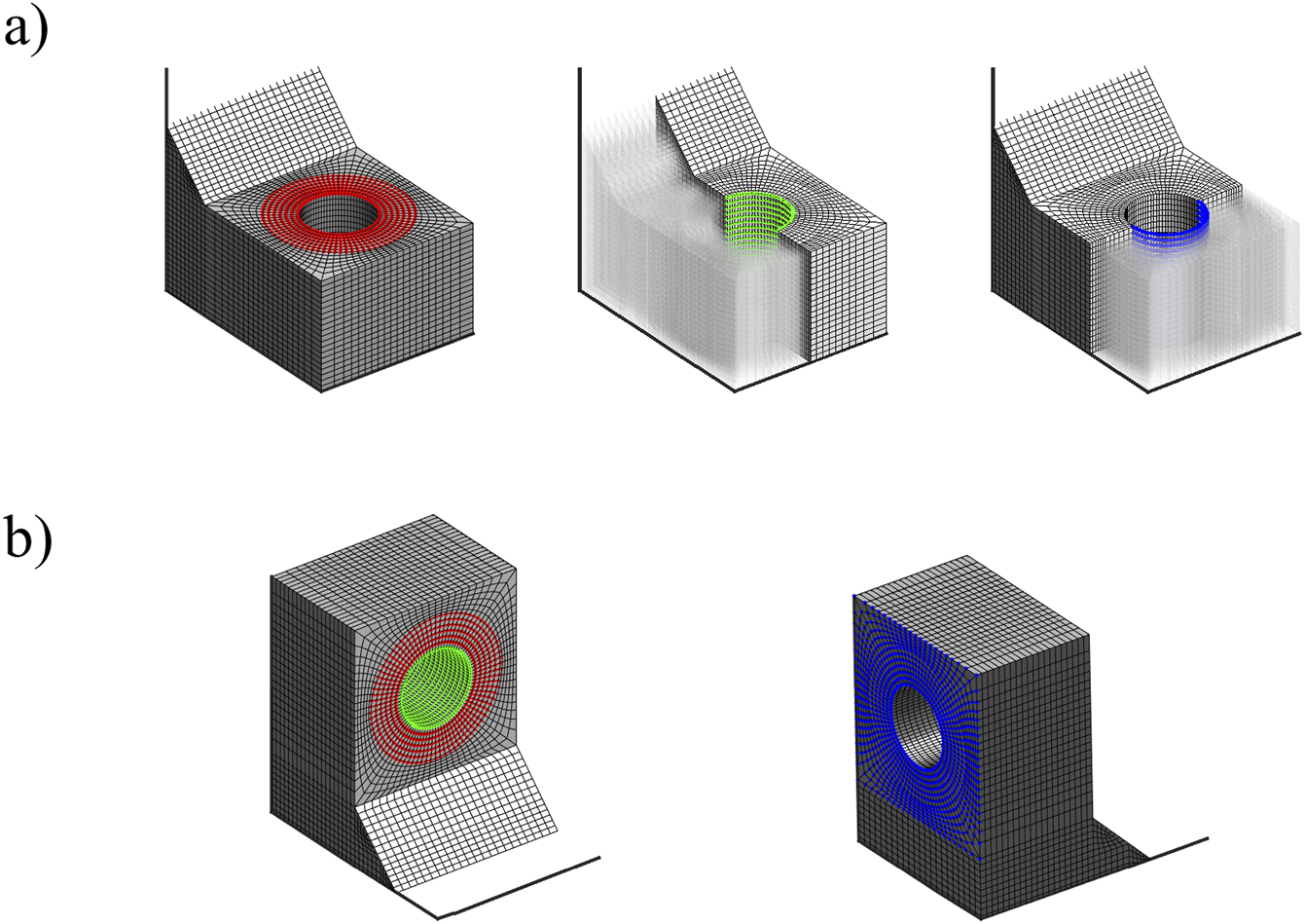
Figure 10 shows the smoothed topologies as well as the orientations for the TOPO and MOTO designs. The orientations shown for the TOPO design are the PSD resulting from the downward-facing load case. The TOPO design shows a vertical bar-like connection between the upper and the lower part of the structure. The MOTO design has more material shifted to the vertical portion of the back of the structure where the TOPO design is rather thin. In both cases the material at the load introduction is oriented along the z-axis, following the dominating load case. At the upper-back of the structure, the material is aligned parallel to the y-axis and normal to the back surface. These regions of thin material or orientations normal to the surface pose problems for the path planning with respect to the requirements defined the corresponding section, also demonstrated in the previous example. Smoothed topologies 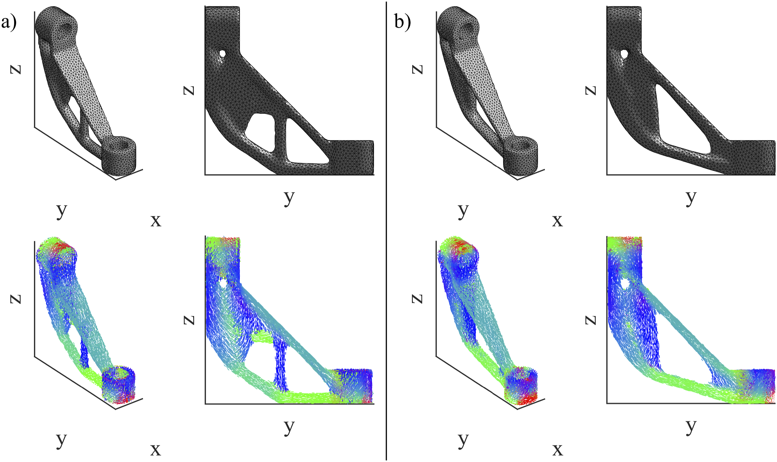
Printing paths for both designs are once more computed using the three planning algorithms. Two paths for the TOPO design are visualized in Figure 11. The paths are computed using the FISO algorithm and the Looping algorithm. Printing paths for TOPO design of L-bracket computed using a) FISO and b) Looping algorithm.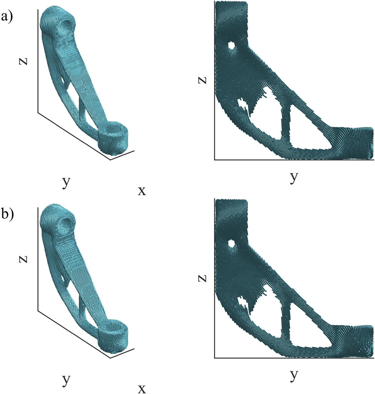
The DLO paths are very similar to the LOOP paths and are included in Figure 15 in Appendix B for completeness. The superiority of the Looping algorithm with respect to load-oriented paths is clearly visible when looking, e.g., at the diagonal surface of the structure. The FISO path shows the characteristic spirals where a lot of material is oriented parallel to the x-axis and therefore perpendicular to the PSD visualized in Figure 10(a). The Looping algorithm respects the input field of directions and produces paths that are much more aligned with the input data. However, all algorithms including DLO fail at filling the rather thin membrane connecting the upper and lower sections of the structure, as there is not enough room on the slices within the topology to fit more than a single path. This leaves an unconnected region, decreasing the structural integrity. The MOTO designs do not exhibit this problem, as all path planning algorithms are able to fully fill the design. As an example, Figure 12 shows the printing paths generated using the Looping method for the MOTO design. The regions around the upper hole are rather similar for all MOTO and TOPO designs. Differences for the lower hole are visible but generally, the orientations in parallel to the center axis of the holes provided for the path planning are traced rather closely except for the outermost surface, where the paths are constrained to the surface. Again, the DLO paths show similar characteristics to the LOOP paths and are therefore not displayed and discussed separately here. Instead, the FISO and DLO paths for the MOTO design of the L-bracket are included in Figure 16 in Appendix B. LOOP paths for MOTO design of L-bracket.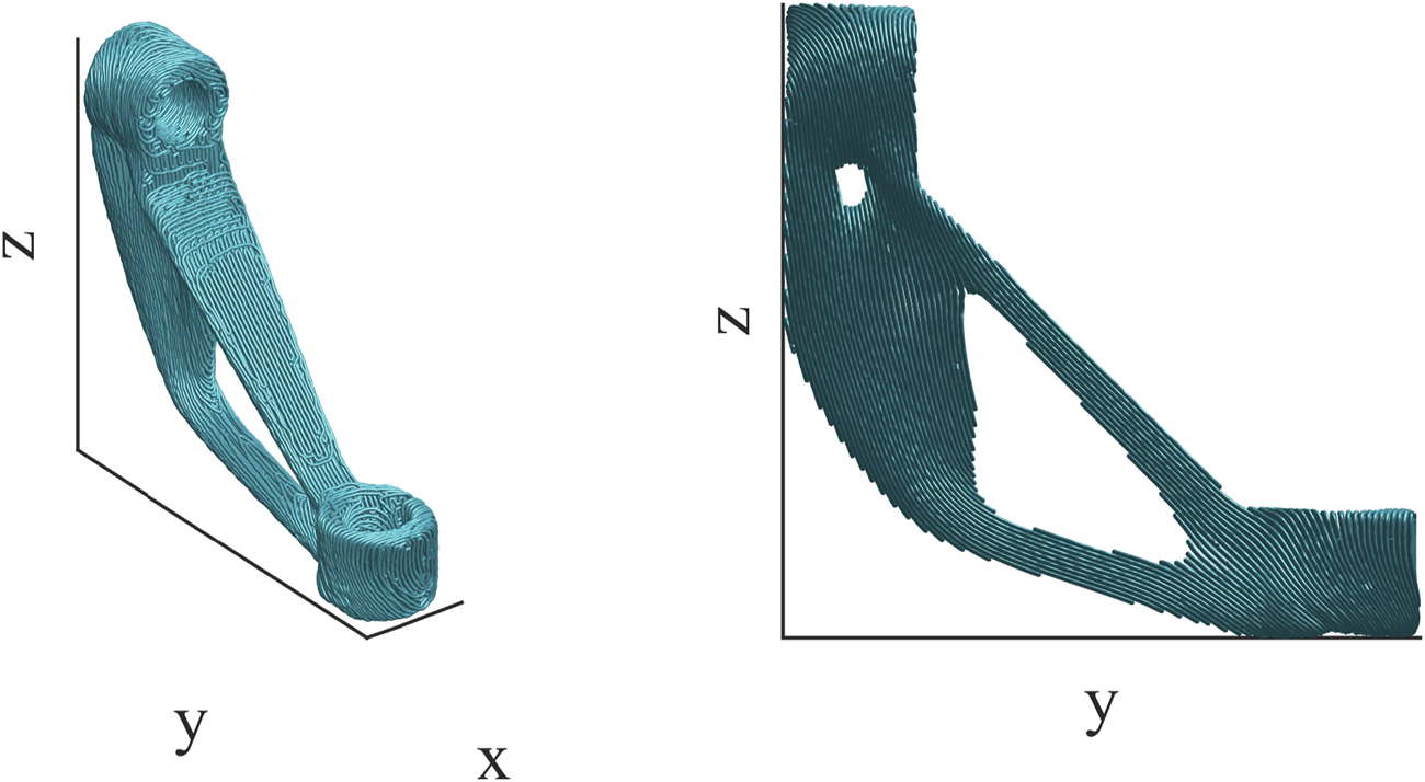
Sum of compliance Σc over three load cases of L-bracket TOPO and MOTO designs using maximum principal stress directions (PSD) from the dominating load case (LC), optimized orientations (OPT) and projected printing paths for material orientations.
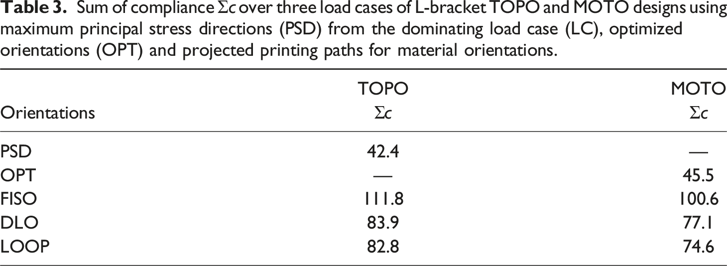
For the numerical analysis of the printing paths computed from the reference designs, the paths are once more projected on the tetrahedral mesh
Even though the TOPO design using PSD from load case 1 is better than the MOTO design having optimized orientations, the printing paths for the MOTO design provide stiffer and therefore structurally better designs in comparison to the TOPO design. This is mostly due to the simpler topology which lends itself to the path planning algorithms in order to compute fully connected paths on the slices. Overall, the MOTO process combined with the Looping algorithm justifies the more involved optimization process for designing the continuously fiber-reinforced part.
Conclusion
This paper investigates the interface between structural optimization for anisotropic materials and modern additive manufacturing (AM) methods by presenting and evaluating a workflow for the design of structures for additive manufacturing using endless fiber-reinforced filament. Two approaches for optimizing the structures are discussed. The first approach is based on a typical isotropic topology optimization (TOPO) and using maximum principal stress directions (PSD) as anisotropic material orientations. The second approach applies a simultaneous optimization of transversal isotropic material orientations and topology (MOTO), enforcing continuity of the material orientations through the use of a regularization filter. The optimized topologies are remeshed as a solid tetrahedral mesh and the orientations for the MOTO design are projected on the tetrahedral mesh. The smooth designs are then processed for AM. A non-planar slicing algorithm accounts for the out-of-plane orientations present in the optimized structures. Three different path planning algorithms are applied to generate printing paths on the non-planar slices: a robust first-in-spiral-out algorithm (FISO), a discrete load-oriented method (DLO) and the Looping algorithm (LOOP) for generating continuous and load-oriented paths. After computing the printing paths, the paths are projected back on the tetrahedral mesh constructed from the optimized topologies. The projected paths are considered as material orientations for a final comparison of the printing paths to the reference designs generated using the two optimization approaches.
The process chain is demonstrated using two examples. The first one is a rather academic example subject to a single load case. The second example draws inspiration from the L-bracket optimization benchmark but introduces multiple load cases as well as holes in the structure for mounting bolts. The numerical examples show that simultaneously optimizing the material orientation and distribution yields different topologies compared to the traditional isotropic topology optimization. For both examples, the TOPO design using PSD for anisotropic material orientations performs as well as or even better than the MOTO design. However, in the presence of multiple load cases, the fully processed MOTO design using LOOP paths shows a better compliance than the corresponding TOPO design. This comparison highlights that such a workflow for designing parts for AM has to be evaluated from start to finish. An isolated perspective on, e.g., the optimization results exclusively would not be sufficient.
In every case, the Looping algorithm produces printing paths that yield the lowest compliance within the FEA in comparison to the FISO and DLO algorithms. Nonetheless, the discrepancy between the simulation results for the optimized designs versus the designs using projected printing paths shows the necessity of further refining the individual processes as well as the communication between them. For example, minimum member thickness as well as avoiding intersections of substructures turned out to be critical in order for the path planning algorithm to follow the optimized orientations as closely as possible.
Future studies have to investigate whether choosing less-optimal but more aligned initial orientation fields yield MOTO designs that can be matched more accurately by the path planning algorithm, as the results from the path planning show that even though the optimization process has a lot of freedom when only considering continuity constraints, the resulting paths conflict with requirements from the manufacturing process, such as contour-parallel paths on the structure’s surface or limiting path curvature. These constraints can be incorporated into the optimization, limiting the design freedom but probably improving the agreement of printing paths with optimized orientations and with that the predictability of the printed structure’s performance.
Following this theoretical investigation, test structures should be manufactured and subjected to physical tests to validate the numerical findings. Therefore, material information from the manufacturing process has to be considered during the optimization process. Eventually, this creates the requirement to refine the material model in order to reflect the varying fiber volume fraction resulting from varying layer height of the non-planar slices. Additional process parameters from (simulating) the manufacturing process such as temperature distribution or heat flow may be incorporated for a more refined consideration of the manufacturing process during the analysis and optimization.
Footnotes
Declaration of conflicting interests
The author(s) declared no potential conflicts of interest with respect to the research, authorship, and/or publication of this article.
Funding
The author(s) disclosed receipt of the following financial support for the research, authorship, and/or publication of this article: This research was funded through the I3 program (Interdisciplinary, Innovative, Engineering (German: Ingenieurwissenschaften)) of the Hamburg University of Technology, 09-719.
Data Availability Statement
All models that appeared in this study are available upon request by contacting the corresponding author.