
Abstract
In structural optimization of fiber-reinforced composites, unidirectional design material is normally applied due to its high anisotropy character. Using volume constraints to save weight often results in truss-like frameworks with defined tension and shear loaded areas, while the latter one is often neglected or improperly described with unidirectional material. Here, a method is proposed to extend the material design space to a continuously variable domain between UD and cross-ply laminates which is simultaneously optimized with topology. This allowed us to increase the design improvement and create smoother material distributions which is more beneficial for fiber placement technologies such as Tailored Fiber Placement. Parameter studies have been performed to investigate the effects of variable shear properties and different design spaces on the structural performance of the final designs, concluding with classical benchmarks to validate the proposed method.
Introduction
In the field of lightweight design, anisotropic materials, especially fiber-reinforced composites (FRP) and their optimization, gain importance in industry. Due to the high material properties compared to the density, FRP can efficiently replace several metal applications. On the other hand, their anisotropic material behavior requires more complex analysis methods to design lightweight structures. In addition to the field of structural simulation, the optimization task has become an essential part of the design process.
In the field of composites, two design approaches can be differentiated: constant and variable stiffness laminates. Ghiasi et al.1,2 give an extensive literature review regarding both design directions. The latter one has the advantage that fibers can be placed in convenient directions such as loads or stress fields, whereas for constant stiffness laminates, only one stacking is defined for the total structure. Hence, it is a disadvantage that fiber orientations cannot be aligned explicitly with load directions which always leads to an unnecessary high mass and thus high costs. Therefore, both can be reduced in an efficient way using variable stiffness laminates.
In order to optimize structures for one of these design approaches, an appropriate manufacturing technique must be chosen at the beginning. For constant stiffness designs, classical techniques such as hand-laying or autoclave methods are frequently used. Commonly used manufacturing processes for variable stiffness designs are Automated Fiber Placement (AFP) 3 and tailored fiber placement (TFP), 4 which use continuous fibers. The structural advantage of TFP technology over AFP is the possibility of placing smaller tow radii and thus increasing the geometrical freedom in the design space. On the other hand, with AFP it is possible to process more mass per time, which is beneficial for larger components, for example, aircraft fuselages. This work focuses on the optimization of smaller components. Therefore, TFP is considered as the manufacturing technique.
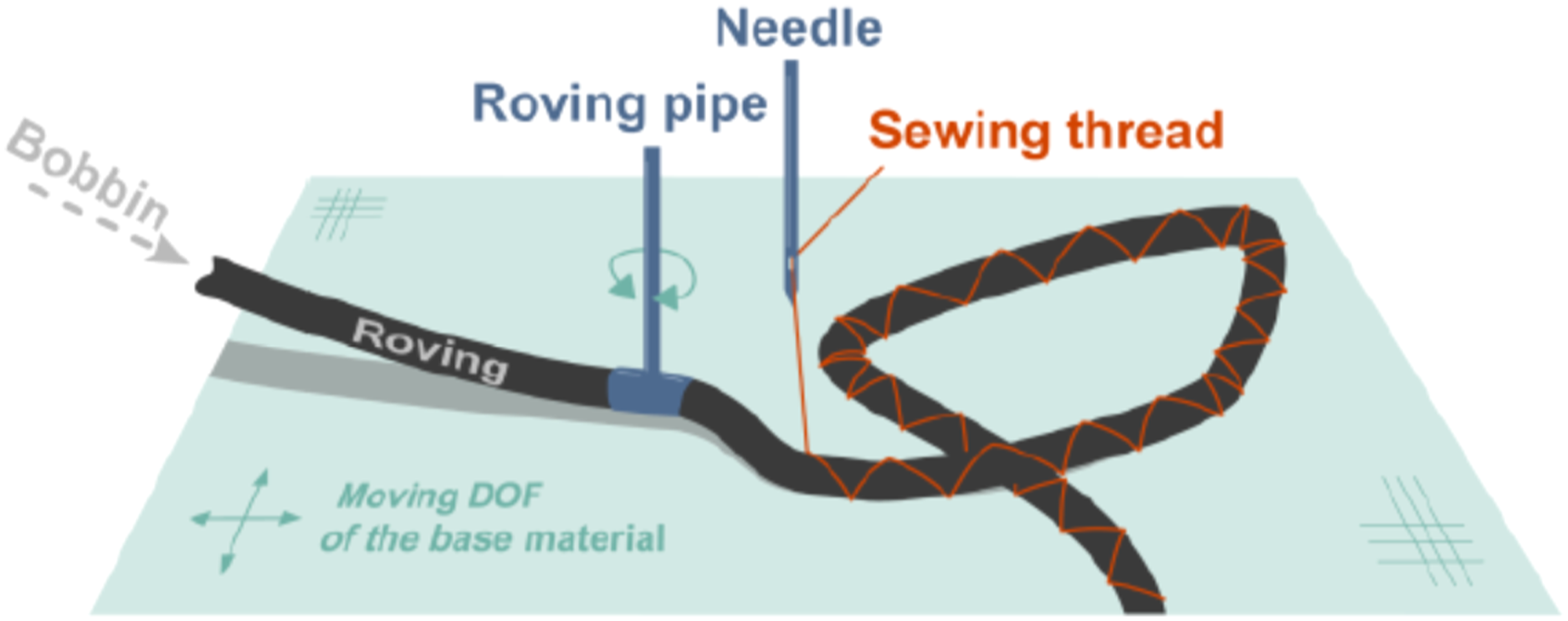
Tailored fiber placement is a variable stiffness process where single fiber tows can be placed with maximum flexible orientation onto a base material (Figure 1). An in-plane movable frame is used to span the base material. The fibers are fixed in a stitching process with a zigzag shape to avoid a high material fraction of the sewing thread. To avoid filament damage, a tow guidance is used to place the tow always next to the needle. The possible material for base material, sewing thread and the placed fiber tow is unconstrained. A lot of research has been conducted to investigate the applicability of different material combinations.5,6 However, in the TFP and AFP production techniques some geometrical parameters are limited. One of these is the radius at which the machine is capable of turning and changing direction, which is constrained to a minimum of 5 mm for TFP and approximately 100 times higher for AFP. Therefore, TFP is suitable for smaller and more detailed structures, especially frame structures with complex intersection and branch points which can be achieved using a topological approach. Tailored fiber placement principle (according to
32
).
Since variable stiffness designs require material properties to be defined locally, for example, at specific nodes or elements in the simulation model, efficient optimization methods are necessary. In literature, many numerical methods have been developed. In terms of anisotropic material, the objective function to be optimized is often non-convex when discrete fiber orientations, number of layers and their respective thicknesses are considered. To improve the quality of the solution and to avoid increased computing time, the following methods have been developed.
For constant stiffness designs, a typical approach for calculating and optimizing composite lay-ups is a layer-wise method which is nowadays implemented in most commercial software packages.1,7 Another approach is a discrete material optimization method (DMO) where the laminate stiffness is calculated as a weighted sum of a set of candidate materials. 8 The last group to be mentioned are direct search methods, especially the genetic algorithm, which improves a population of solutions using Darwin’s law of survival.9,10 The main disadvantage is the intensive computation time, which increases exponentially with the number of design variables.
In the early stages of variable stiffness optimization research, Pedersen11,12 analytically investigated the behavior of global and local optima of variable stiffness material and thickness distributions considering the minimization of elastic strain energy for simple structural cases. Since results are based on a fixed stress or strain field, structures that are more complex require numerical investigations due to a varying field. Based on this research, Setoodeh et al.13–15 used these principles to develop a framework, which uses cellular automata to update local material orientations iteratively including multiple load cases. Given the fact, that only fiber orientations and layer thicknesses are used as design variables, global optima could not be achieved when considering general laminates. Therefore, Gürdal et al. developed a concept to optimize16,17 and manufacture 18 variable stiffness structures for Automated Fiber Placement applications (AFP) using lamination parameters. First introduced by Tsai et al. 19 lamination parameters (LP) provide an efficient way for composite material parametrization instead of layered laminate stacking to reduce the number of design variables. Subsequently, the structure can be optimized with gradient-based algorithms. Nevertheless, the pure lamination parameter approach has the disadvantage of a missing physical laminate definition, for which an additional optimization step is crucial.
Additional work has been conducted by Kriechbaum, who developed the CAIO method (Computer Aided Internal Optimization 20 ), which is based on principal stresses and tree growth, earlier investigated by Mattheck. 21 In this method, orthotropic material axes are aligned according to the major principal axes and are subsequently optimized in an iterative process. It should be noted that only one load case can be analyzed using CAIO. Based on the work of Kriechbaum, the Leibniz Institute of Polymer Research in Dresden further developed the CAIO method especially for tailored fiber placement 6 (TFP) using principal stresses and a 3D-modeling approach. TFP is a single fiber placement technology which allows the highest design freedom for composite materials, for example, small turn radii in contrast to AFP. Especially addressing local fiber crossings in TFP optimization as shown in Figure 1 will be part of the current work.
Additionally, Bittrich et al.22,23 developed an approach called Direct Fiber Path Optimization method (DFPO) based on B-Splines to take thickness accumulations directly into account. Although the results are promising, only applications with one load case can be optimized, which leads to a constrained scope. To increase the range of possibilities, Zink et al. 24 developed a projection method for multiple load cases using the superposition principle as well as an analytical approach. In short, the main function computes a best-fit material orientation by maximizing the sum of the projected principal stress magnitudes of all applied load cases. In the current work, the used laminate stackings are partly implemented in a more general way.
Pedersen et al. showed that material optimization is only the first part when considering lightweight designs. Hence, thickness optimization is necessary to achieve a true variability in stiffness. Topology optimization (TO) is an adequate method which is widely investigated for isotropic materials. To mention the most important researches, Michell 25 first published a paper on topology optimization. Bendsoe et al. 26 started investigations on numerical methods which are nowadays implemented in common commercial finite element software packages. The most important approach is the SIMP method 27 (Solid Isotropic Material with Penalization). Further research can be found in the review by Rozvany 28 .
On the other hand, anisotropic topology optimization is a newer research field in which investigations were conducted to combine anisotropic material and topology optimization. In general, different ways exist to determine the anisotropic material tensor. Jantos et al. 29 used Euler angles and a material filter to create a continuous material and thickness distribution. Nomura et al. 30 investigated an approach using a tensor field variable. Peeters 17 used lamination parameters to define the material in the objective function. Finally, Li et al. 31 used a homogenization approach for a set of material orientations to construct a multi-material TO.
It is shown that in most cases the material definition is restricted to a unidirectional material orientation except for Peeters using balanced laminates.
As the first part in the present work, we propose an extension to the lamination parameter approach. Since a pure unidirectional fiber orientation field does not provide sufficient information about the shear load capability at the intersections of topological designs, we developed a framework extending the design space with selected stacking types using continuous fiber orientations. Based on this, the compliance problem for the pure material optimization step results in a clear design space where global optima can be achieved at each design point.
The final part consists in the combination of the extended material optimization and a topology approach which results in an anisotropic topology optimization for the design process for TFP structures for which the new extension can catch the most important occurring stress states.
Furthermore, the previous research showed that the first step for optimizing weight-reduced TFP components often consists of an isotropic topology optimization followed by a material optimization. Both steps can now be replaced by one with the advantage that the influence of the anisotropic material behavior on the structural shape is already taken into account.
Regarding topology optimization, it is important to note that the optimum thickness distribution of structural compliance problems is achieved using close-walled instead of the typical open-walled designs. 33 Nevertheless, those structures are theoretical optimums which are often not manufacturable. Therefore, this paper focuses on truss-like topology designs which are especially suitable for tailored fiber placement applications as reinforcements of larger assemblies or independent parts as well.
The design process for TFP structures can be divided into 3 steps: the material and thickness optimization, the fiber path generation and detailed modeling. Since the first optimization step only gives a first design proposal, this paper focuses on step 1 with a 2D implementation with an extended design space for material orientations which provides an additional support for the subsequent fiber path generation step. Furthermore, thickness accumulations and base material, which are necessary for the final modeling step, will be part of future investigations and are not considered in this work.
To begin with, the optimization approach is described including a sensitivity analysis and an overview of the overall framework. Some steps are based on previous work, for example, the objective function used by IJsselmuiden. 16 Those are explicitly marked with citations.
Optimization problem
In this work the main focus will be on the combined optimization of compliance problems and topology optimization in order to achieve suitable material distributions and topologies for structural tailored fiber placement applications. Later on, other objectives like failure criteria or buckling are possible.
Since a domain Ω can only be optimized for a fixed deformation field, the optimization is placed in a global iterative scheme. In each iteration, an element-by-element local optimization is performed based on fixed nodal displacements which are updated by a finite element analysis. The scheme continues until the change of the global solution is sufficiently small and a preset convergence criterion is fulfilled. In the following, more detailed information is provided for the in/outputs.
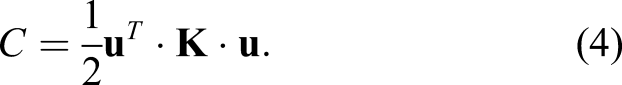
The maximization of stiffness or minimization of compliance is a frequently used optimization objective for topology and material distributions. Especially for anisotropic materials the simultaneous consideration of both, topology and anisotropic material orientations, is crucial.
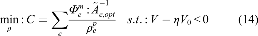
For simultaneous operations the minimum compliance in general can be expressed in a domain Ω as

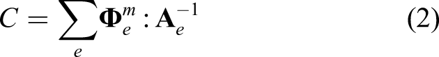
According to IJsselmuiden
16
, C can be written for 2D structural problems in a general way based on a Taylor series as
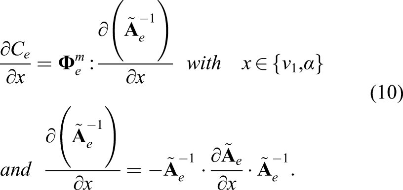
The sensitivity matrix contains the gradients of the element stiffness matrix
34
with respect to
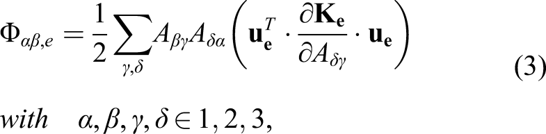
The sensitivity matrix is computed in each iteration of the global optimization step after the displacement field update in an FEA.
One of the important aspects in terms of structural optimization are multiple load cases. This is achieved with
Using these basic principles the local optimization can be conducted which is divided into material and a topological step. In the following, both steps and their analytical design variables are explained in detail.
Extended material design space
In the introduction it was shown that in most cases a unidirectional material tensor has been chosen for an anisotropic topology optimization. The next sections will show that at least two fiber orientations are appropriate for the design of TFP structures. Therefore, an efficient parameterization of the A-, B-, and D-matrices known from classical laminate theory is required.
TFP parts are commonly constrained to 2D shell structures or curved shells in 3D space due to manufacturing reasons. For the parametrization, it has been decided to use lamination parameters as an intermediate step which provide a simple calculation without extra transformation. The most important advantage resides in the efficient implementation of other objectives and more complex laminate stackings which are crucial for TFP topology, especially for multiple load cases.
In this work, the description is constrained to the
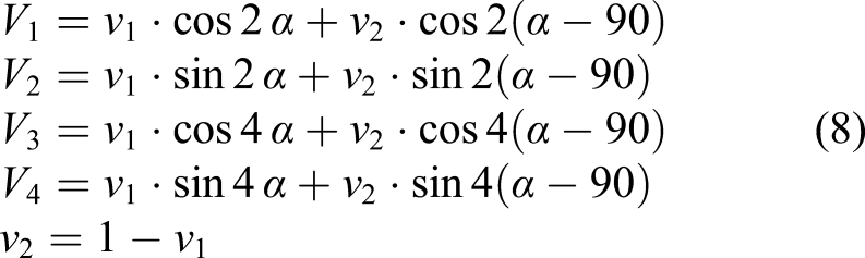
The lamination parameters of the in-plane stiffness V
i
with -1 ≤ V
i
≤ 1 depend on the fiber orientation as follows
Nevertheless, the design does often depend on the manufacturing technique. In this case, tailored fiber placement is applied that necessarily requires fiber continuity. Therefore, when considering the optimum distribution for topology and material simultaneously with a given volume constraint, laminate stackings consisting of two layers are more appropriate than a single fiber orientation and may be sufficient to describe most load states. Concluding, fiber orientations can be used, since the number of design parameters do not exceed those of lamination parameters. LP are only used as a simplified parametrization in this work and to extend the functionality of the algorithm for future investigations.
In order to optimize general laminates all four lamination parameters are required leading to an infinite number of possibilities to express real fiber orientations in a post-processing step.
In literature several investigations have been conducted using an orthotropic unidirectional material orientation 29 with one angle α. Furthermore, the optimization in terms of lamination parameters has often been constrained to symmetric and balanced laminates to reduce the number of design parameters. From a manufacturing point of view, this is not beneficial when topology optimization is considered as shown in the examples.
During a topology optimization the design is often driven to a truss-like framework which consists of truss members and their intersections. The optimum found by unidirectional material orientation does not guarantee fiber continuity at the intersections since these points carry loads in more than one direction. Therefore, the design space is extended from unidirectional laminates to cross-ply laminates and their transition zone as shown in Figure 2. In the following, the defined design space is called mixed cross-ply. Flowchart of the full optimization Process.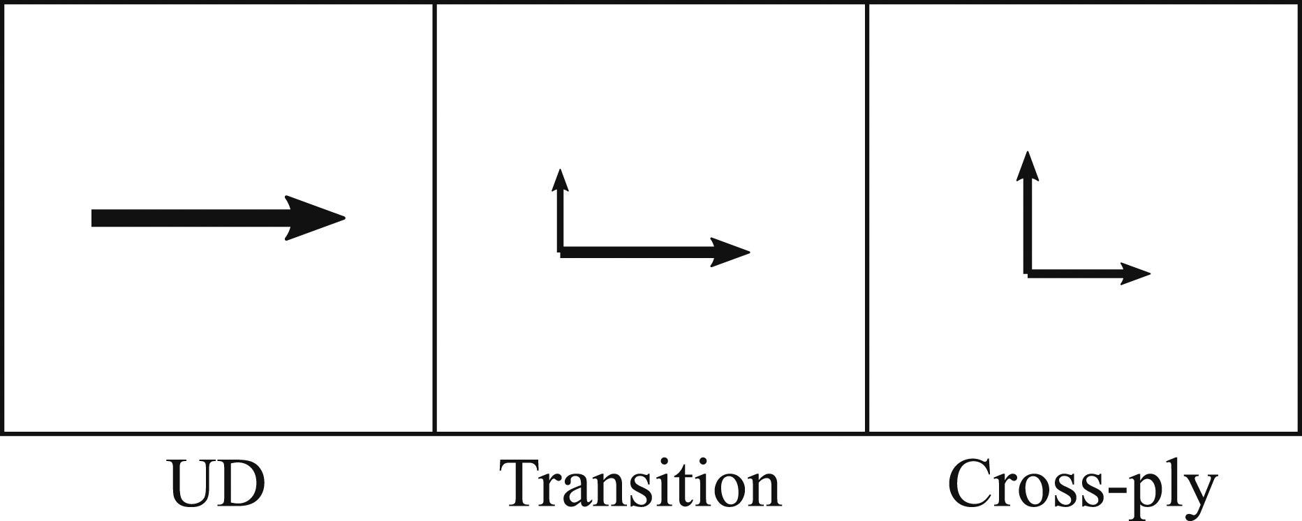
The additional optimization step of finding appropriate fiber orientations can thus be avoided. Zink et al. 24 already introduced the importance of unidirectional off-axis as well as cross-ply laminates to catch tension and shear dominating areas, respectively. Zink’s approach is extended by the transition zones and put into a simpler mathematical relation. In the following, an analytical derivation of the extended design space is presented.
First, we consider a two-ply laminate which is sufficient to describe the defined design space. In terms of symmetry, the laminate would consequently have four plies. Based on (7), the equations for the lamination parameters can be written as
This results in a two-dimensional local optimization problem as

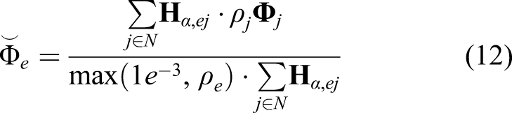
Finally, the sensitivity matrices can be filtered using a distance-based sensitivity filter known from classical topology optimization. As a result, the material orientation distribution can be smoothed which is especially useful for the optimization in unidirectional design space. Furthermore, the filter can be scaled using densities from the previous iteration to reduce the effect of void areas which is computed as

Topology optimization
When the topology is considered as a second optimization step, the objective can be rewritten using (6) as
This equation shows that all design parameters have an influence on the compliance, but they do not depend on each other. Hence, the total optimization problem can be divided into two minimization problems, so that densities and material parameters can be optimized separately during the same iteration.
Since only the material dependent part
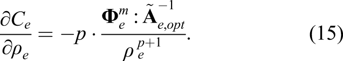
The penalty factor p forces a 0–1 thickness distribution and is commonly chosen as 3. As mentioned earlier, using p = 1 results in the global optimum of closed-walled structures but with a higher difficulty to be manufactured.
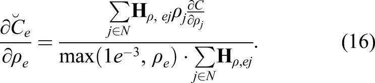
Furthermore, a mesh-independent sensitivity filter is used for topology optimization as well to create clear contours. The equation to filter the local sensitivities is used from literature as
After the local optimization is done the compliance is updated with an FEA using the optimum design points. If the design change compared to the previous iteration is less than a preset value, the optimization is stopped. Otherwise, the optimization is conducted again within the next iteration. To sum up, the overall optimization process is shown in Figure 3. Extended design space: Mixed cross-ply.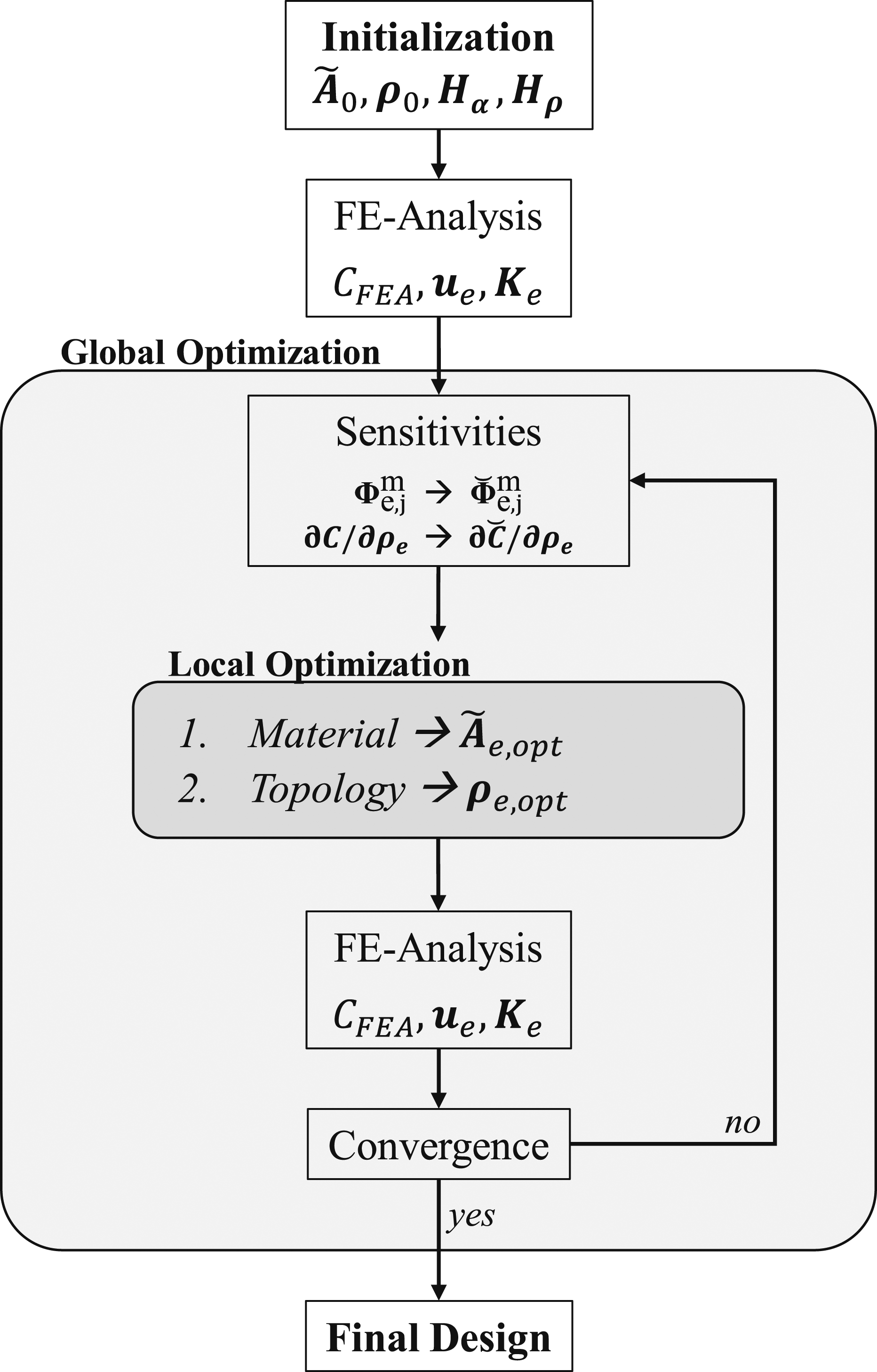
Results
Model descriptions
In this section, different examples are presented for a validation of the material optimization and for different investigations in combination with an optimum thickness distribution.
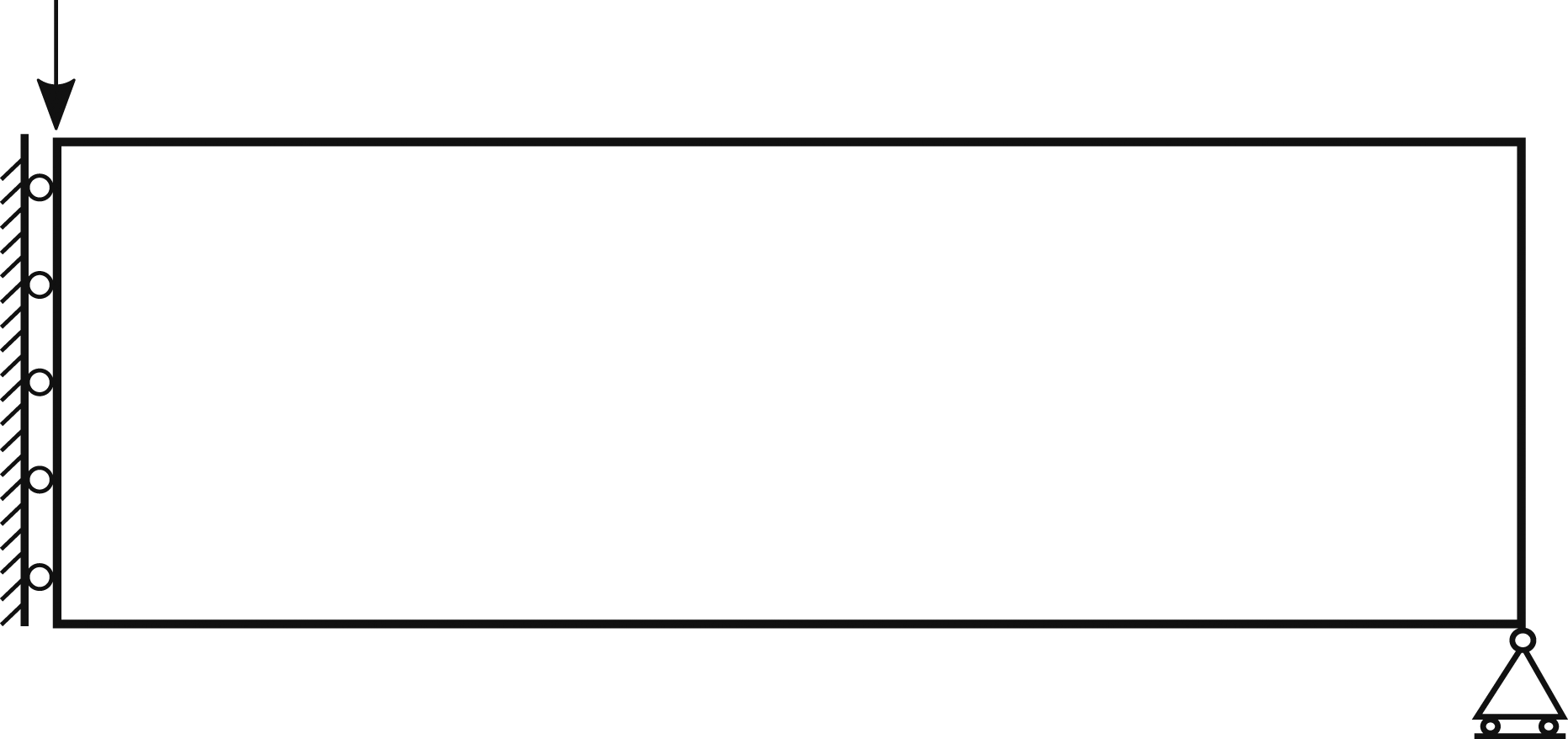
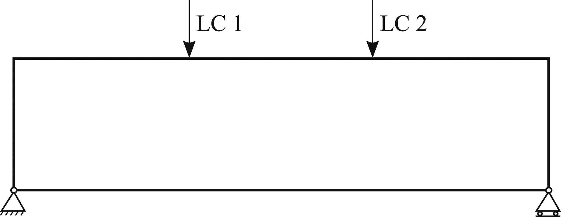
The first example is a classical bending problem (Figure 4) which is used for a validation of the optimization method. The second example is the MBB (Messerschmidt–Bölkow–Blohm) beam (Figure 5) that is often used as a benchmark in the field of optimization. The last example to validate multiple load cases is a four-point-bending problem as shown in Figure 6. Example 1: Sym. bending problem (aspect ratio 3:1). Example 2: 3-Point-Bending benchmark (MBB, aspect ratio 3:1). Example 3: 4-Point-Bending problem (aspect ratio 4:1).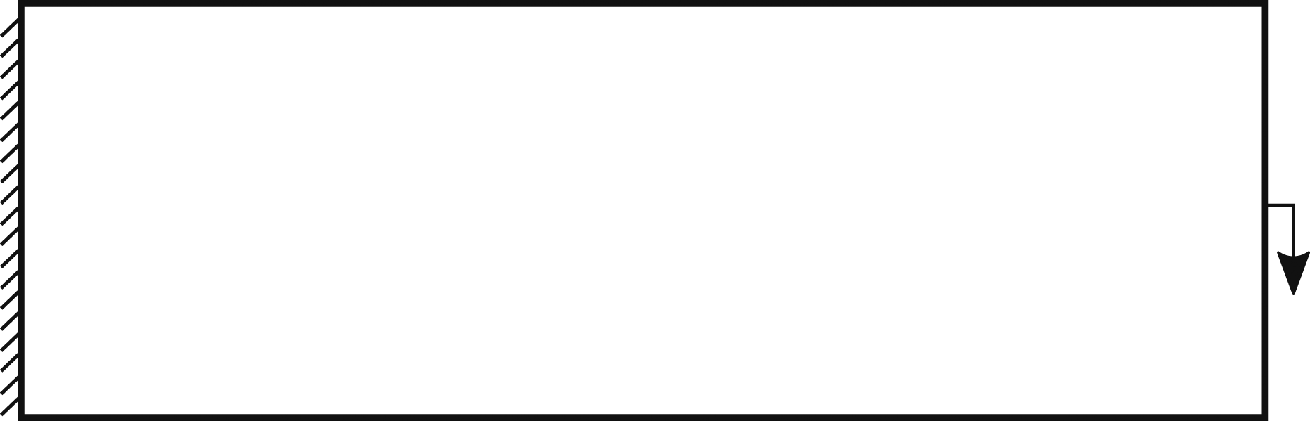
During the optimization process all examples are analyzed with quadrilateral, fully integrated plane stress elements (CPS4) in ABAQUS/Standard to achieve a higher accuracy and to avoid hourglassing as well. The sensitivities for the optimization are computed based on the nodal displacements. In order to simplify the examples, the maximum allowable thickness is set to 1 mm. Furthermore, the reference axis of the anisotropic material is set to the horizontal direction for all examples.
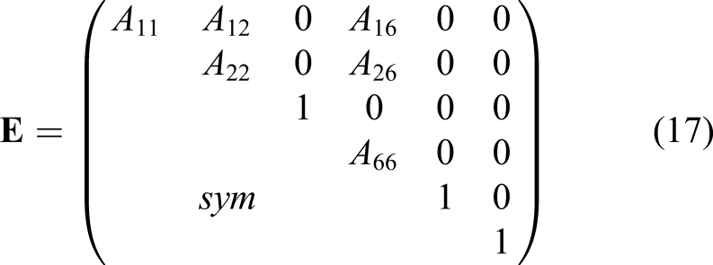
The material is implemented via the full anisotropic elasticity matrix. Since only symmetrical laminates are used, only a maximum of four lamination parameters is necessary to describe the A-matrix, and matrix D is simplified to an identity matrix to avoid singularities and due to in-plane loads only

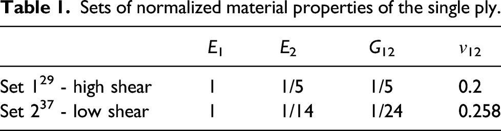
Sets of normalized material properties of the single ply.
The effects of different filter settings have been carefully investigated in literature. Hence, the factor for the filter radii of the material and topology optimization are set to 3 and 1.5, respectively. For this reason, a mesh convergence study has been omitted and for all examples the element size is set sufficiently small with a characteristic length of 0.5 mm in combination with the given filter parameters.
Influence of the initial material distribution
From literature the initial material distribution for anisotropic material optimization is often chosen differently. Nomura et al. 30 proved their method using isotropic material as the initial guess, Silva et al. 38 only used a 0° fiber orientation and Jantos et al. 29 applied the principal stress orientation based on isotropic material. Since the principal stress approach is constrained to single load case problems and other anisotropic distributions may strongly depend on the model definition, different initial guesses are investigated first.
The first and the second example are optimized for UD design space in order to investigate the influence of the initial material distribution on the optimized design. The initial designs are chosen as follows: the absolute principal stress orientations, which are evaluated based on an isotropic FEA, a 0° configuration in horizontal direction, the simple isotropic case as well as an asymmetric distribution of 45°. All designs are compared according to the stiffness which is normalized to the initial isotropic stiffness. The volume fraction for topology is set to 50% for all examples.
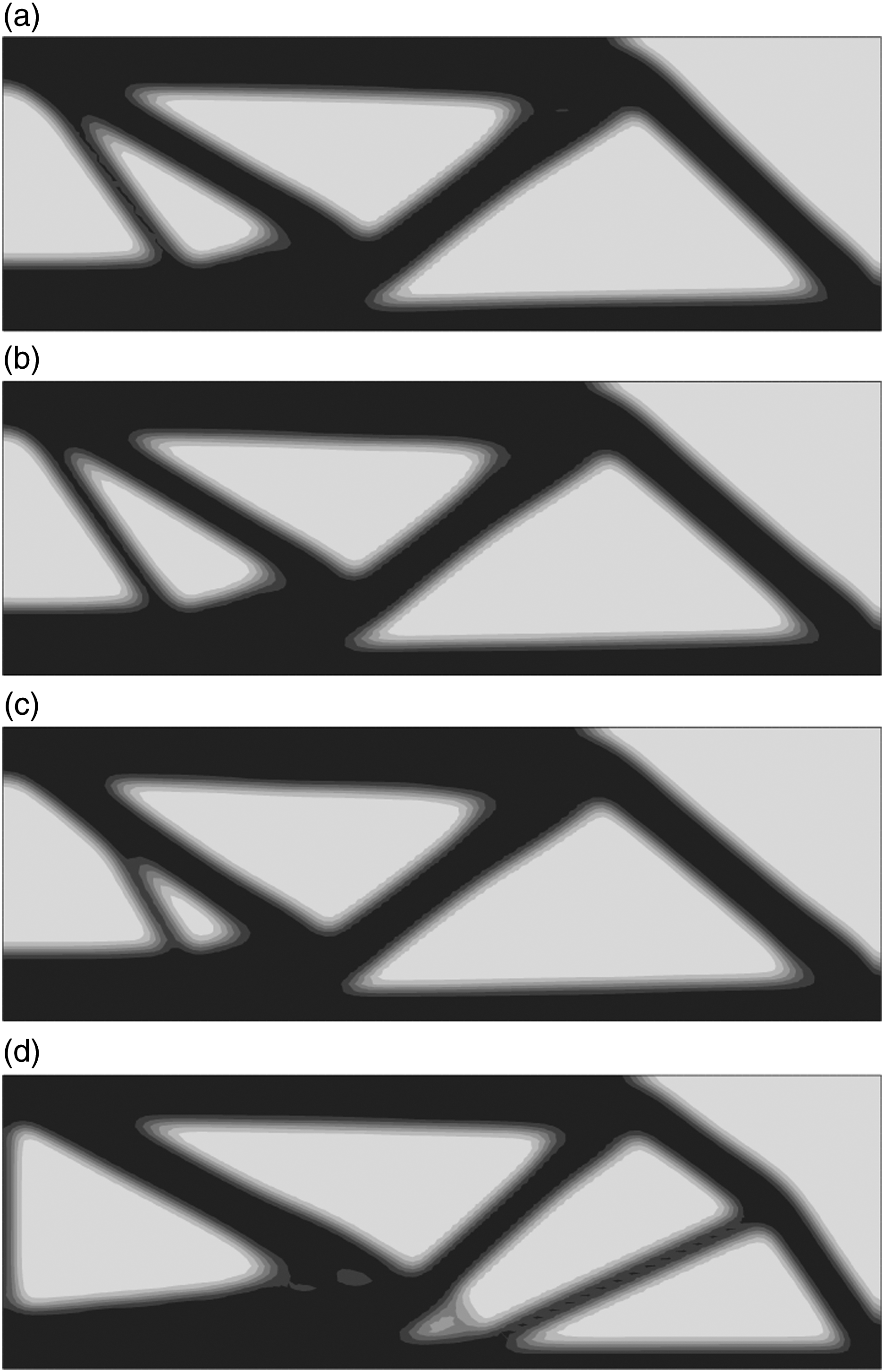
The optimized layouts for all cases of both examples are presented. Two scenarios are demonstrated. Example 1 where model symmetry axis and material reference axis coincide (Figure 7) and example 2 where both axes do not match (Figure 8). Both are compared with (a)symmetric initial guesses. Optimized topology at iteration 30 for example 1 using different initial material distributions: (a) Isotropic, principal and 0° (symmetric initial guess), (b) 45° (asymmetric initial guess). Optimized topology at iteration 30 for example 2 using different initial material distributions: (a) Isotropic, (b) Principal, (c) 0°, (d) 45°.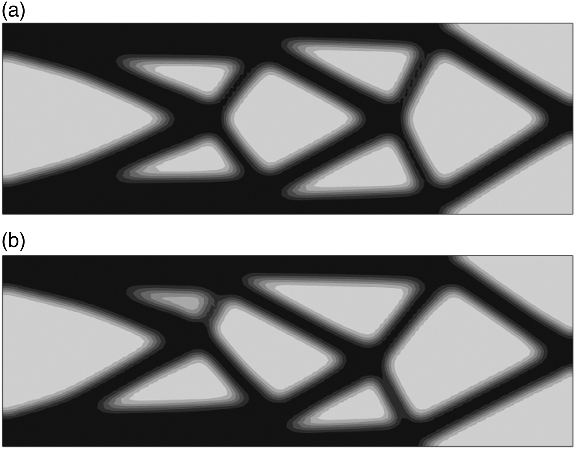
Example 1 shows almost the same symmetric designs for all initial guesses except for the 45° orientation, which takes more iterations to converge to the same result. In terms of the normalized stiffness, Figure 9(a) indicates no meaningful dependency of the initial guesses regarding the final design as well. Normalized stiffness, compared for different initial material configurations: (a) Example 1, (b) Example 2.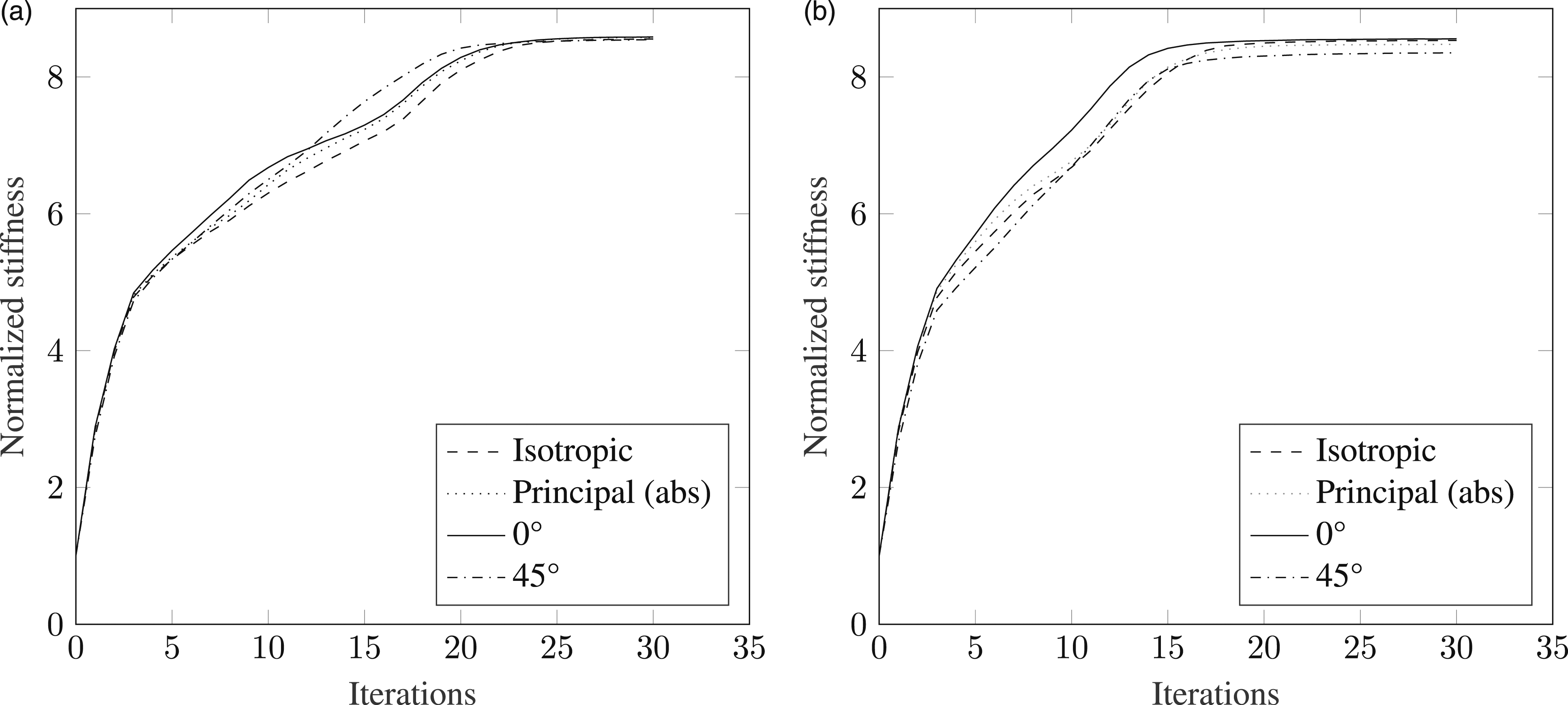
Regarding Figure 9(b) example 2 shows a similar behavior, but with considerable differences in topological design and stiffness. With the 0° orientation, the highest stiffness is achieved, directly followed by the isotropic and principal stress distribution. The 45° guess appears to be less suitable.
In conclusion, no explicit decision is possible which initial material configuration suits best for the optimization. Similar results are achieved using isotropic and principal stress direction for the final structural design. For the special cases 1 and 2, the 0° configuration is beneficial but not generally transferable to more complex structural problems. For this case, isotropic material would be the best choice. Especially for multiple load case problems an initial principal stress distribution is not possible since principal stresses can be only obtained for a single load case. An additional step would be necessary to combine the principal stress distributions of all load cases. For this, the reader is referred to Zink et al. 24
Number of start points in local optimization
The previous investigation included only the UD design space. When considering the extended space of mixed cross-ply, another influence factor to be investigated is the number of starting points in the local optimization step. Since the design space of mixed cross-ply is a two-dimensional gradient problem with local/global optima as well as saddle points, different patterns of initial points are considered and the resulting structural performance is compared for the examples 1 and 2.
The patterns of initial points are demonstrated using a single element model (see Figure 10). The element is constrained by two symmetric boundary conditions and two load cases are applied biaxially. Single element model including two load cases with pure tension.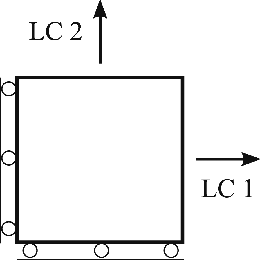
In order to validate the optimization results a 3D representation of the compliance is found by iterating over the complete design space, exemplary for a load ratio of 3:1 (Figure 11(a)). The presented compliance is normalized to the maximum value depending on the material orientation α and the ply fraction v. The global minimum is marked with a red point, which is a mixed cross-ply. One saddle point exists for the ± 45° case and global maximum solutions for either 0° or 90° when considering both load cases at once. Therefore, multiple initial guesses may be required. Three different patterns are investigated: 1 × 1, 2 × 2 and 3 × 3 (divides the space at the quarters and half positions), regularly distributed as shown in Figure 11(b). It is important to note, that the model definition in Figure 10 is not representative for any arbitrary loading in each element. This is a special case which results in a point symmetric behavior with half of the design space for α sufficient for the optimization. Mixed cross-ply for single element compliance behavior for load ratio 3:1: (a) Normalized compliance distribution over the design space, (b) Initial point patterns 1x1 and 2x2.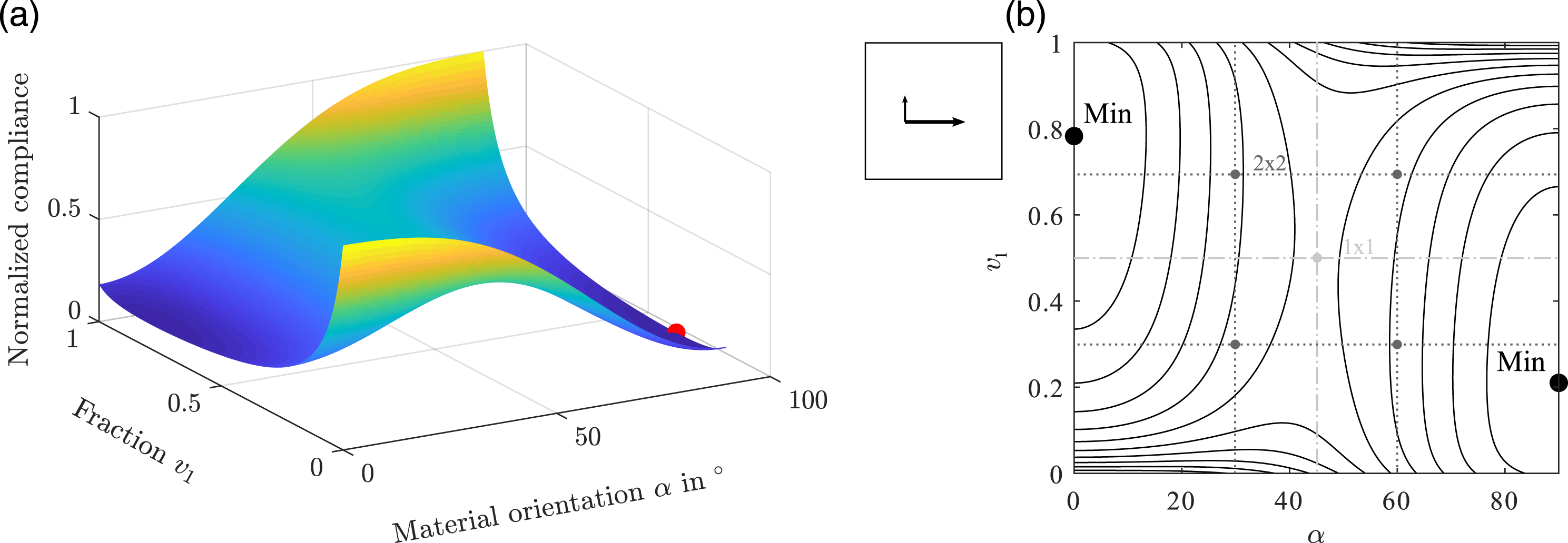
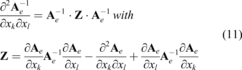
Whenever a starting or optimum point is recognized as a saddle point using (10) and (11), an additional loop is run to check the decent slope near this point for further consideration.
In order to show the influence on the more complex example 1, the normalized stiffness is compared for all patterns. Additionally, the computation time for the material optimization is recorded in order to show the efficiency. Figure 12 indicates almost the same optimization behavior for all patterns with a slight decrease in stiffness when 1 × 1 is applied to the optimization. On the other hand, a faster computation for the 1 × 1 pattern due to a significantly reduced number of initial points is possible. Comparing the mean computation time results in a 60% reduction for the 1 × 1 pattern in contrast to 2 × 2. The 3 × 3 pattern shows redundant results and is not further considered. In all further investigations, the 2 × 2 pattern is chosen. Comparison of different initial point patterns for the local optimization (example 1) in terms of stiffness.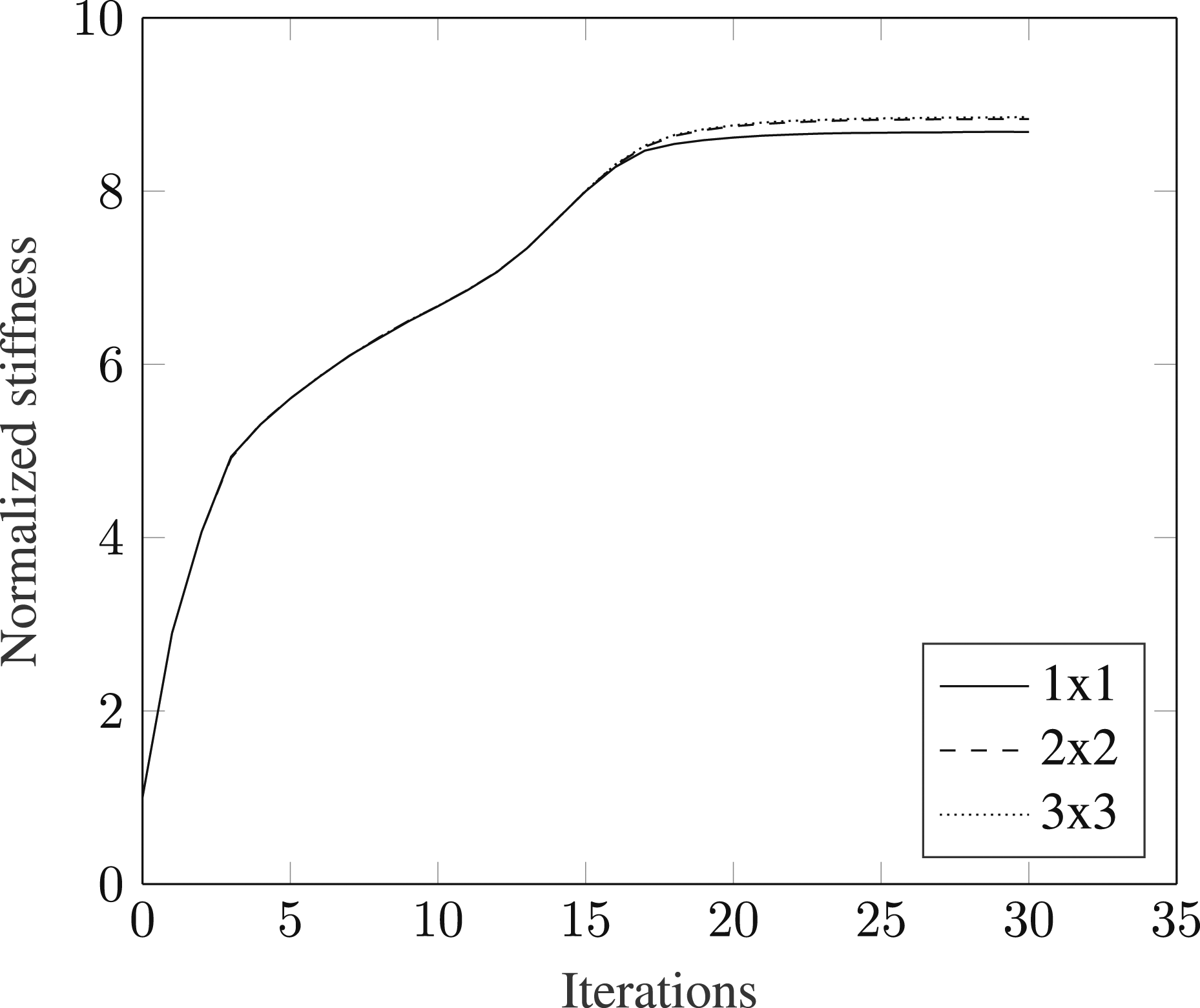
Effect of material properties
In this section, the influence of different material properties on the structural and the convergence behavior is investigated for the presented method. The previous results have been achieved for the material set 1 using a relatively high transverse and shear modulus. In the following, those material data are compared with lower shear material (set 2) which are the result of a material characterization with real TFP manufacturing parameters. Both material sets are normalized to the longitudinal fiber direction and transverse and shear modulus are given as fractions.
From Table 1 it is evident that a large difference exists especially for the shear modulus. Due to the fact that the extended mixed cross-ply design space is used to catch the shear dominated regions of a structure, the shear modulus is varied between both material sets to show the effect of the new design space over the UD space.
An overview is given for example 1 using both material property sets with additional design spaces which are used in literature such as the balanced laminate region and the classical isotropic topology optimization. All results are normalized to the latter one to show the relative stiffness increase.
In Figure 13(a), it is demonstrated that the mixed cross-ply and UD design space show the highest relative stiffness that was achieved using material set 1. The difference between both is very small with slightly better results for mixed cross-ply since the shear modulus is very high compared to the longitudinal stiffness. Hence, the shear loads can be sufficiently transferred using UD material. The lowest stiffness is achieved with the classical isotropic topology approach where no preferred material direction exists. Various design spaces compared for different material sets; validation in terms of a general lamination parameter design: (a) Material set 1 (high shear modulus), (b) Material set 2 (low shear modulus).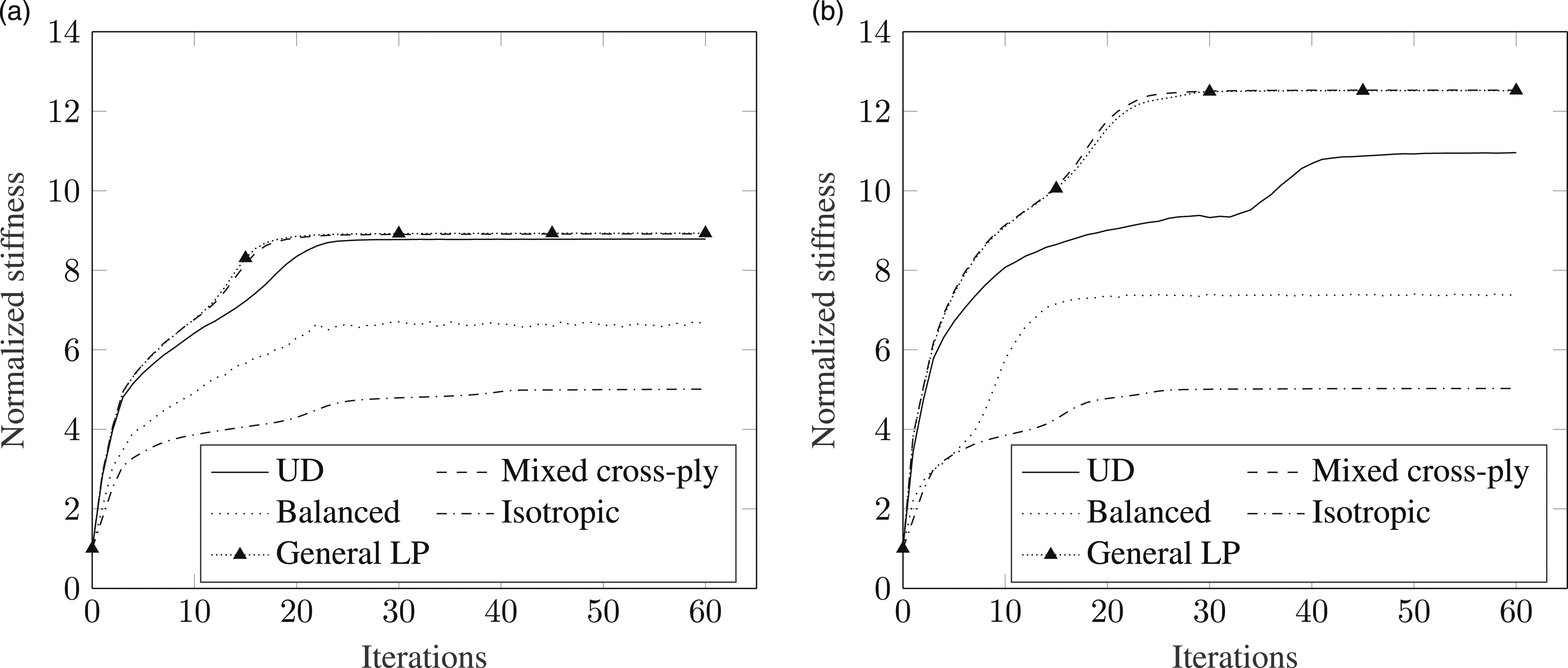
Balanced laminates show intermediate results since only orthotropic material behavior is possible. It is obvious that balanced laminates are not appropriate for truss-like frameworks if a penalty factor higher than one is used. In this case, material orientations do not always follow design contours so that for placed fiber tows a technique with cut function such as AFP is required. For TFP, this function does not exist; hence, fiber tows have to be continuously placeable. Therefore, balanced laminates are inefficient due to the discontinuous load transfer between load introduction and boundary conditions. The result is an instable convergence behavior with a lower optimized stiffness design.
An additional investigation has been conducted for validation. Therefore, the compliance was directly optimized in terms of all four lamination parameters for the A-matrix to show the maximum possible design space. For a detailed theory, the reader is referred to IJsselmuiden16. The result shows a good agreement with the mixed cross-ply domain. It can be concluded that the extended design space presented in this work is more appropriate than UD material and sufficient for an anisotropic topology optimization without an extra post-processing in order to obtain physical fiber orientations.
The same investigation is conducted using material set 2 with a comparable low shear stiffness. In Figure 13(b), the results are demonstrated. The order of design spaces from the best to the lowest stiffness are the same but with substantial differences. First, with mixed cross-ply laminates a significant higher relative stiffness is achieved compared to UD. Second, UD material shows a slower convergence behavior since the low shear modulus is insufficient to find the appropriate local optimum in shear dominated regions. Thus, the laminate shear modulus has to be increased using a second material orientation. Using the mixed cross-ply design space results in a faster convergence behavior. Finally, all investigated design spaces show a significant increase in relative stiffness compared to the initial model configuration and the high shear material set 1 in Figure 13(a).
In order to visualize the results from Figure 13, the optimized material distributions are presented in Figure 14 for the most interesting regions, the intersection points of a topological design. The topology and stiffness for material set 1 are similar for both design spaces. Furthermore, a differentiation between UD and mixed cross-ply becomes more irrelevant with an increasing shear modulus. In the Figure 14(a) and (c), the optimized material distributions end up in a singular point due to an ambiguity with multiple stiffness optima. Optimized material distributions for UD and mixed cross-ply design space using both material sets: (a) Set 1 - UD, (b) Set 1 - Mixed cross-ply, (c) Set 2 - UD, (d) Set 2 - Mixed cross-ply.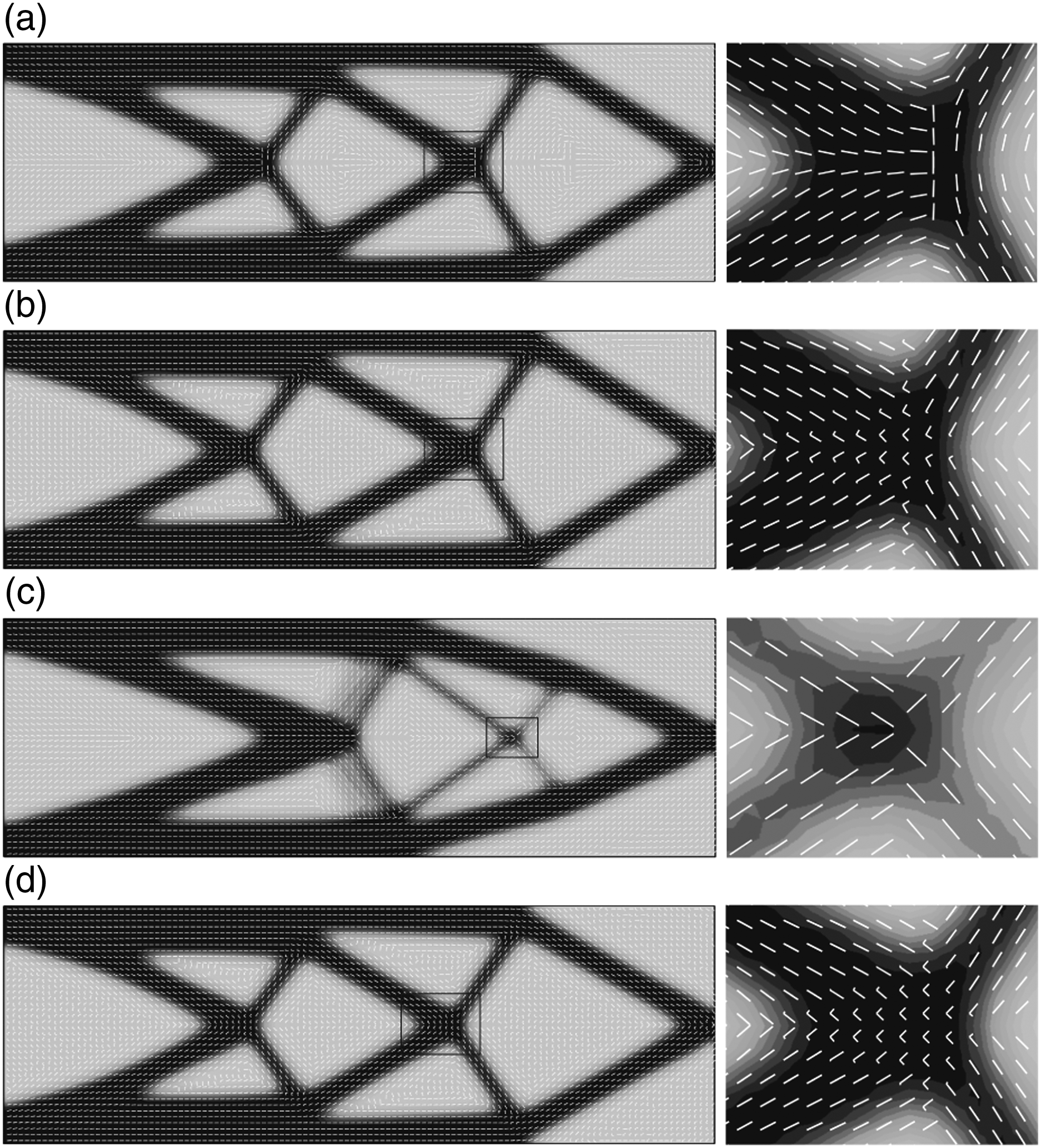
Ambiguity can be avoided with at least two fiber orientations (Figure 14(b) and (d)). Both designs show a straighter course of possible fiber tows without any tangential alignment to the horizontal axis or singular regions (see Figure 14(a)). Hence, TFP manufacturability is feasible without running into inner structural borders that has to be avoided.
To show the different design of intersection points for the optimized material distribution of both material sets, the marked sections of two designs have been manufactured with a Tajima embroidery machine as shown in Figure 15. The designs for set 1 (UD) and set 2 (mixed cross-ply) are applied to highlight the advantages of the latter one for TFP optimization in contrast to the first one from previous studies. Due to the low shear modulus in material set 2 the UD fiber distribution (Figure 14(c)) shows a similar discontinuity as set 1: UD (Figure 14(a)). Therefore, only the maximum improvement is presented with the manufactured designs. Manufactured intersection points for different optimized material distributions: planned fiber paths (left), real fiber paths (right): (a) Set 1 - UD, (b) Set 2 - Mixed cross-ply.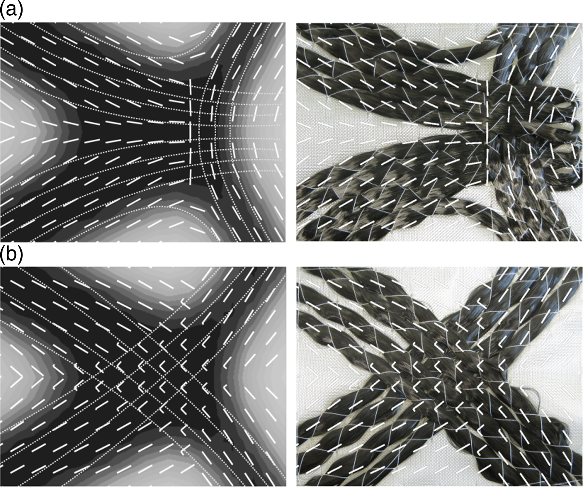
The first difference is the singular point in Figure 15(a) as mentioned earlier, which complicates the automated path generation due to high angular material changes. In this example, the tow paths are planned manually to circumvent this problem. The filtering of UD orientations causes the material to align horizontally for this benchmark. Hence, turning points inside the structure cutouts have to be defined due to TFP manufacturing constraints, which needs to be avoided.
Second, besides the optimized material, the topology is not reached at the center line due to the tangential fiber alignment. Furthermore, empty spaces may occur, which will be resin dominated regions after the infiltration process. Those areas will be weak points in terms of stiffness and strength.
Regarding mixed cross-ply in Figure 15(b) a continuous material flow is possible from one truss member to the opposite. According to the material orientations and the topology, tows can be placed without much loss of information. Only stiffness decreases must be accounted for due to changing cross-section between the truss members. For example, the fiber tows from right to left have to be placed densely and sparse according to the truss member width, which may cause resin dominated areas.
In summary, mixed cross-ply are more suitable for placing TFP tows. Furthermore, the design convergence is also more reliable using mixed cross-ply with a higher independence of material properties.
The different behavior of mixed cross-ply and pure UD optimized structures can be further analyzed considering a material shear modulus varying between 5–20% of E1. Set 2 is used for the remaining data. In Figure 16, the normalized stiffness is investigated for a uniformly increasing relative shear modulus. For both examples 1 and 2, it is obvious that the importance of the mixed cross-ply design space increases with a decreasing relative shear modulus. Variable shear modulus (relative to E1): stiffness increase of mixed cross-ply over UD material in %.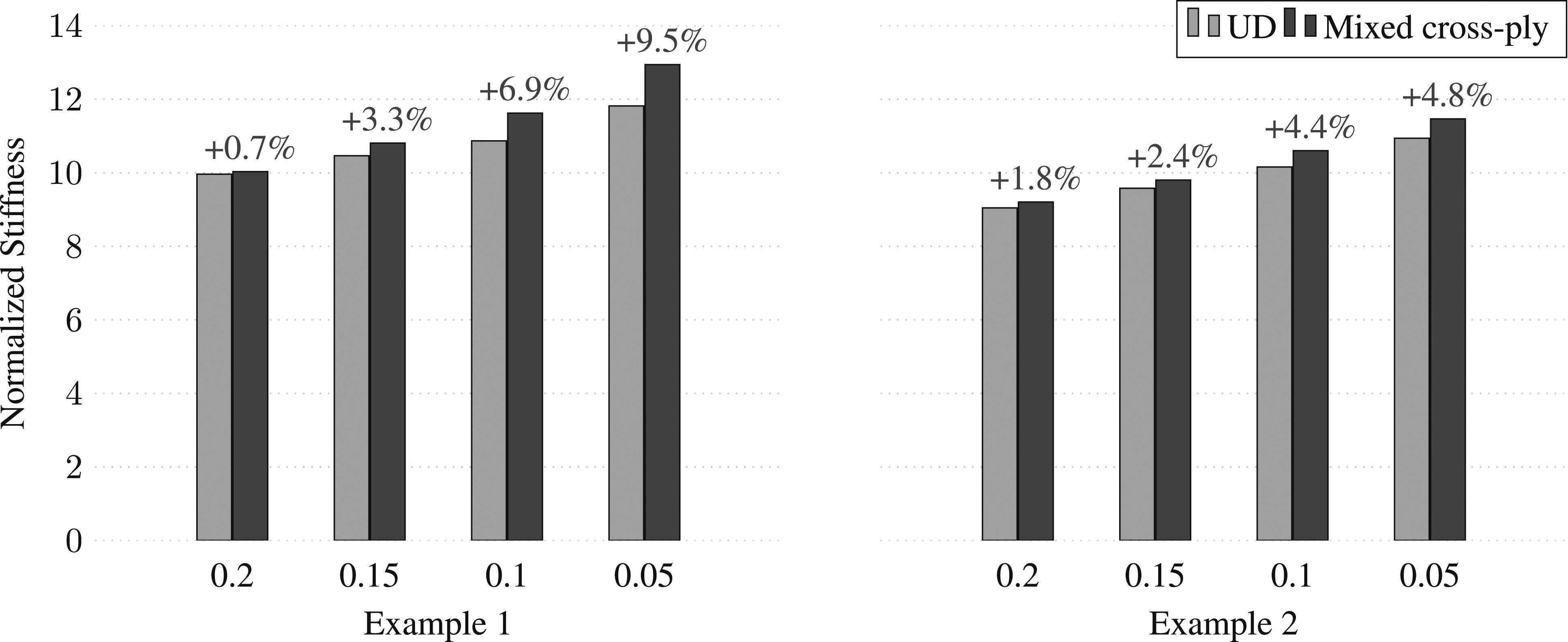
It has to be noted that this parameter study is only generic since for real fiber-reinforced composites E2 is not constant for a varying G12. Both parameters are linked to Young’s modulus of the resin and thus not independent.
Regarding both examples 1 and 2, up to 10% and 5% higher relative stiffness, respectively, can be achieved with mixed cross-ply compared to a unidirectionally optimized structure. Additionally, from Figure 13(a) and (b), it can be stated that a faster convergence behavior is possible using mixed cross-ply. This effect becomes more important with a decrease in shear properties. Using UD material often results in numerical instabilities for shear-weak materials.
Comparing normalized stiffnesses related to the initial model definitions allows for an independent consideration of optimization results regarding different material parameter sets. Therefore, an additional trend is demonstrated in terms of an overall design improvement. This can be obtained when the shear modulus is kept low.
Multiple load cases
The final investigation includes example 3 with multiple load cases. Both loads are applied in separate load cases resulting in different displacement fields which are combined within the sensitivities according to (5). Considering both loads applied in the same load case is omitted due to earlier investigations, for example, Nomura et al. 30
In Figure 17, the optimization results are presented for both material sets and both design spaces, UD and mixed cross-ply. The comparison of relative stiffnesses (Figure 17(a)) for all four combinations confirm the behavior shown for example 1. The relative stiffness improvement using lower shear material is higher than for high shear moduli, where no significant change is achieved using mixed cross-ply. Optimization results for multiple load cases in example 3: (a) Relative structural stiffness, (b) Set 1 - UD (c) Set 1 - Mixed cross-ply, (d) Set 2 - UD, (e) Set 2 - Mixed cross-ply.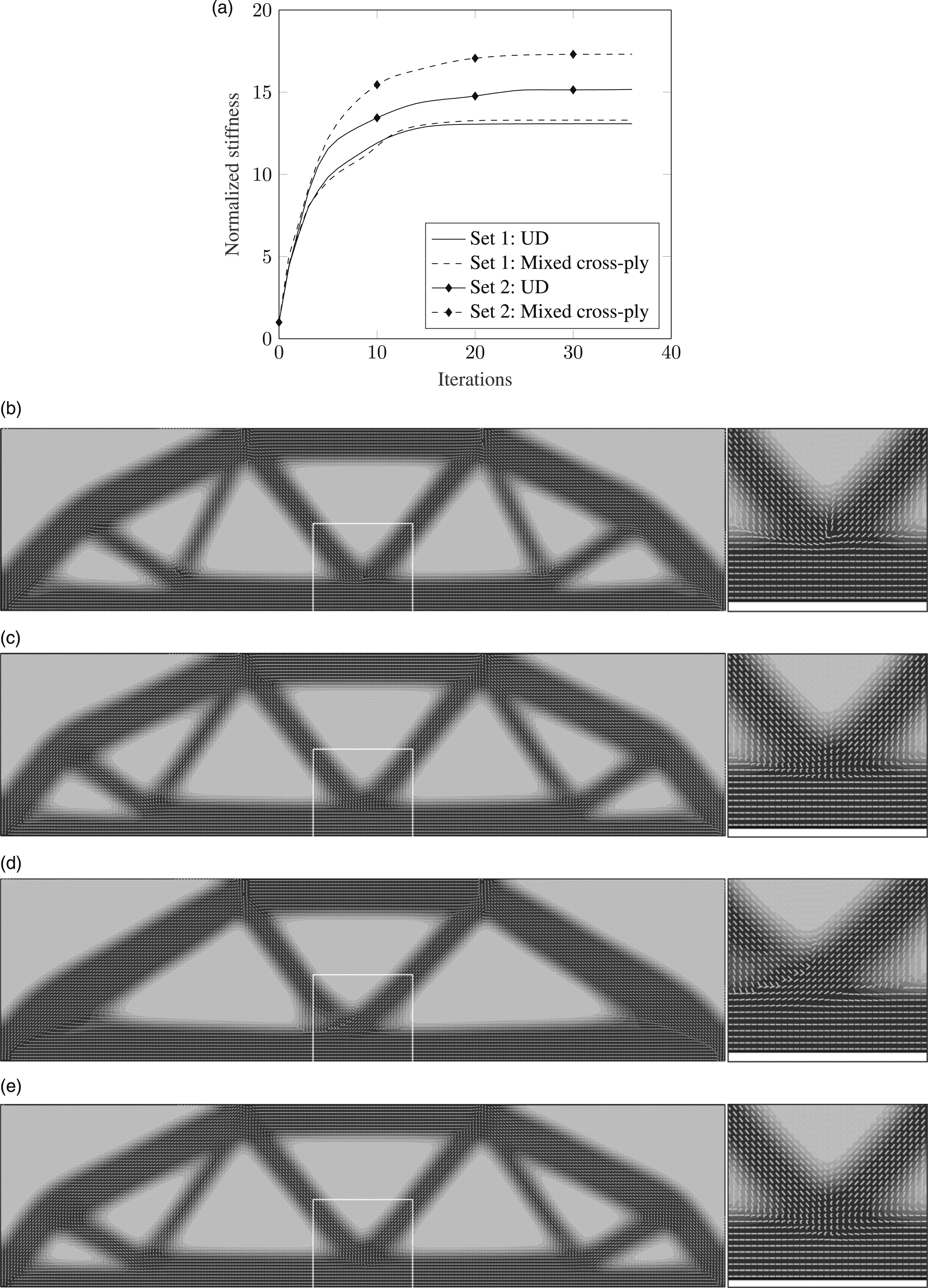
Furthermore, the extended design space has an influence on the numerical stability of the optimization. In Figure 17(d), the centered zoom frame indicates a certain asymmetric behavior during the optimization. Small changes in both model halves are accumulated iteratively which may lead to significant design changes. This may be caused by improper settings of the local optimizer and the level of orthotropy. Usually this measure is defined as the ratio of longitudinal over transverse stiffness of the layer material. Since the order of transverse and shear stiffness is similar within each material set, the level of orthotropy is used in this context. In terms of shear moduli, a ratio of 5 is obtained for material set 1 where set 2 has a ratio of 24, which may cause the instabilities. This is omitted using a mixed cross-ply domain that results in perfectly symmetric designs with higher relative design improvements.
Conclusions
In this work, an extended anisotropic topology optimization approach is developed. The design space is expanded from unidirectional to variable cross-ply laminates and their transition in order to describe the material state in more complex regions, for example, intersection areas. Therefore, different parameters are investigated such as initial configurations, the influence of start points and material properties. The results are demonstrated for various examples.
The highest impact has been identified for variable material sets with a different level of orthotropy. It has been demonstrated that the mixed cross-ply design space is beneficial for materials with a high level of orthotropy and multiple load cases without using additional filtering in contrast to unidirectional material orientation. The results show smoother material distributions at intersection areas, which simplifies the subsequent step of fiber path generations.
Finally, the presented method proved that more efficient structural designs are possible relative to the initial configuration while the computation effort of the optimization process can be reduced due to a faster convergence behavior.
Footnotes
Declaration of conflicting interests
The author(s) declared no potential conflicts of interest with respect to the research, authorship, and/or publication of this article.
Funding
The author(s) received no financial support for the research, authorship, and/or publication of this article.