
Abstract
In this research, an effort has been made to explore the feasibility of nanoparticle reinforcement of barium titanate (BTO) in PVDF/Dimethylformamide (DMF) polymeric solution for DIW application. This study also explores the feasibility of 2D printing a box pattern for developed polymeric composite ink using dispenser-based phenomenon on the platform of Microplotter proto printer which is capable of printing high viscosity inks up to 450cp. The study also explores the fluidic response of developed ink to control its printability. The results suggest that 5 wt% PVDF/DMF solution works without any difficulty in nozzle ejection. The density and viscosity of the composite ink increase with increased BTO content. The highest recorded values for density and viscosity in the PVDF/DMF solution matrix reinforced with 28 wt% BTO are 1275.6 kg/m3 and 57.6 cP, respectively. The surface tension observed to be decreased above a 24.5 wt% reinforcement, attributed to the dominant hydrophilic nature of BTO at higher concentrations. Additionally, a feasibility study on 2D printing of the developed inks indicates success, as the inks were effectively printed using a dispenser-based technique. Thus, a higher BTO-reinforced PVDF/DMF matrix can be used in future studies for better piezoelectric yield which is crucial for sensor applications.
Introduction
Flexible electronics is a dynamic field that presents numerous challenges and opportunities across materials science, fabrication techniques, and various application domains. 1 With significant potential benefits for advancing robotics and prosthetics through soft, foldable, and stretchable electronic systems, this technology is now on the brink of becoming highly innovative and exploratory. 2 The emergent field of flexible electronics is thus in need of new materials and processing techniques to meet various application needs. 3 In such a way, the development of flexible and stretchable electronics, enabled by compliant materials, is expected to bring about a radical change in the manner humans interact with devices and redefine the possibilities with which electronics could be integrated into an array of environments. 4 This field has advanced further with innovations such as 3D printing, additive manufacturing, and a combination of hybrid manufacturing processes. Certain experiences have expanded the application range of flexible electronics, leading to development in wearable technologies, bio-sensing, conformal electronics, and energy systems. 5 Technologies such as inkjet printing, direct ink writing (DIW), and fused deposition modeling (FDM) have aided rapid realization of new flexible electronic devices possible. 6
3D printing enables the creation of various multifunctional and complex devices, effectively integrating mechanical, optical, chemical, and electronic properties. 7 DIW has emerged as a promising candidate for making high-performance super capacitors for flexible and wearable electronics. 8 The technique allows direct printing of materials onto different flat and conformal substrates, which makes them suitable for wearable device and on-chip integration applications. 9 Variety of inks have been synthesized, characterized and tested for 3D printing of flexible electronic components using DIW. 10
Inkjet printing, has experienced a significant increase in usage over the past decade for fabricating flexible and wearable electronic products owing to unique features like ease of use, simplicity, high resolution, reduced waste, and superior detailing. It employs a variety of nano reinforced composite inks. Several research groups are exploring inkjet printing for wearable application by printing 2D design on flexible substrate.11,12 However, some of the challenges which exist for inkjet printing is viscosity, dot spacing and printability of ink on its platform. 13 Further the detailing on substrate also depends over the choice of material, printing parameters of process and other fluid dynamics of selected functional ink. 14 Abdullah et al. 2016 15 observed that PVDF thin films deposited on different substrates (silicon, glass, ITO-coated glass, and silver-coated glass) all exhibited the β-phase crystalline structure, but with different molecular chain orientations. Matavz et al. 2017 16 observed thin polymeric layers (a few nanometers thick) can be used to modify the surface properties of substrates and mediate the wetting of inks during inkjet printing. Soum et al. 2023 17 demonstrated use of PES substrate that has a dual-porous structure, with nano-sized pores in the upper layer and micro-scale pores in the lower layer, which allowed for high-density aggregation of conductive ink nanoparticles and quick absorption and drainage of the ink solvent.
Similarly, electrospinning is also one technique which is capable of producing nano sheets of piezoelectric material for sensor applications. May studies exist which have used PVDF as base material and reinforced BT nano particle for fabrications of sheets capable of generating electrical output for sensor applications. 18 One such study reported piezoelectricity output of 18 pC N−1 through electrospinning PVDF/BT composite ink. 19 One study has optimized PVDF/Fe3O4 (10 wt%) and MWCNT (5 wt%) composition for improved energy outputs. 20 Many other studies exist which have highlighted different PVDF based matrix for EMI shielding and improved piezoelectric behaviour.21–24
Other manufacturing processes like FDM also offers flexibility of material selection and material fabrication at lab scale to produce low-cost sensors, 25 but the rigid nature of feedstock limits its suitability in flexible electronics. Several researchers have suggested optimization of FDM process variables such as layer resolution, build orientation, raster angle, flow rate, speed, nozzle, and platform temperature, to enhance the build quality and performance. 26 Still the FDM lacks industrial acceptance due to limited usage in actual product development and it is limited to conceptual and demonstration purpose only. 27 Similarly, Metamaterial 3D printing has also enabled advancements in flexible electronics such as stretchable electronic skin (e-skin). Researchers have investigated variety of material compositions reinforced with nanoparticles like CNTs, graphene, and carbon nanorods.28–30 Flexible electronic substrates are gaining traction owing to their lower weight, wearability, optical transparency, and flexibility. 31
Thus, material selection is crucial for the not only for the desired performance and functionality of flexible electronics but also ensuring compatibility with various manufacturing techniques. For flexible wearable electronic applications, PVDF-based composite materials have proven to be a promising option due to their flexibility, mechanical strength, chemical stability, biocompatibility, and ease of fabrication. 32 While PVDF possesses a piezoelectric constant d31 of roughly 35 pC/N within the ambient temperature range, this value tends to drop at lower temperature. 33 It has been established that poling of PVDF can effectively enhance the β-phase content from 56% to 83%. 34 Furthermore, pure PVDF has relatively low electrical conductivity and dielectric permittivity 35 and by reinforcing it with suitable matrix the issue of low electrical response for PVDF matrix can be addressed. Variety of conducing and non conducting fillers such as graphite, multi-walled carbon nanotubes, ZnO, or BaTiO3, have been used by the researchers to enhance the electrical and EMI shielding capacity of the materials,. 36 Such modifications result in increased β-phase content of PVDF thereby drastically improving the d33 piezoelectric coefficients. 37
The addition of BaTiO3 nanoparticles to PVDF increased the piezoelectric voltage generated by the composite material, with the highest voltage of 6 V observed for a composition of 20% PVDF and 25% BaTiO3. 38 Researchers realize several reinforcements in a PVDF matrix to improve the piezoelectric property of the polymer. The colourless film of PVDF-ZnO (15 wt%) nanocomposite generated ∼1.81 V open-circuit voltage, ∼0.57 μA short-circuit current, and provides maximum power density of 0.21 μW/cm2, making it fit for application in energy harvesting and powering small electronic devices. 39 The PVDF/Bi2Al4O9/RGO nanocomposite film had a high remnant polarization of 0.0189 μC/cm2 and generated a significant electrical output of 5.92 V and 0.76 μA. The addition of Bi2Al4O9 and reduced graphene oxide (RGO) nanofillers increased the fraction of the piezoelectric β-phase in the PVDF polymer from 53% to 76%. 40 The rGO-doped PVDF and rGO- polyaniline (PANI)-coated PVDF nanofiber mats produced maximum output voltages of 7.84 V and 10.60 V, respectively, when used as piezoelectric nanogenerators. 41 Kim et al. 42 observed that the piezoelectric voltage and current outputs of the PVDF-BTO composite-based nanogenerator were maximized at 10 wt% BTO, where the Young’s modulus was also highest. Alluri et al. 43 has noticed that the BTZO/PVDF hybrid film nanogenerator produced a higher electrical output (up to ∼11.9 V and ∼1.35 μA) compared to the BTO/PVDF nanogenerator (7.99 V and 1.01 μA). Many studies have proposed a few crucial drawbacks regarding the incorporation of BTO into PVDF. For instance, Pandey et al. 44 reported that achieving well-dispersed and a stable one for composite materials may not be that easy to reach. In particular, it should be noted that piezoelectric materials are now a popular topic of research that is advancing quickly and widely. However, investigation of the parameter space, from solvent ratios, to PVDF concentration and BaTiO3 incorporation (into various solvents and with various drying conditions) is minimally explored in the literature to date. 45
Scope for the study
Piezoelectric materials, particularly polyvinylidene fluoride (PVDF), have shown potential in flexible electronics, particularly for energy harvesting and sensor applications. Further research is needed to improve performance, increase β-phase content, and explore alternative reinforcement materials. Limited studies on solvent ratios, PVDF concentrations, and filler addition percentages could lead to significant advancements in piezoelectric nanogenerators.
Also, much remains unnarrated on the exploitation of inkjet printing via a dispenser-based phenomenon which is capable of producing ultrathin films with better piezoelectric and mechanical behavior. Very few studies have investigated ink optimization for inkjet printing to develop ultrathin piezoelectric films with improved mechanical and electrical properties through dispenser-based printing especially using Microplotter proto printer. Nano modifed PVDF based ink may give a suitable solution to ultrathin film fabrication for improved rheological, mechanical and electrical properties.
Also, the previous literature reflects the limitation of inkjet printing for higher loading of filler in polymer matrix primarily due to issues related to non ejection of drops through nozzle using piezo force. In the present study, an effort has been made to address this gap by optimizing ink formulations with varying BaTiO3 concentration in a PVDF matrix especially for inkjet printing through dispenser-based phenomenon. We evaluate the resulting properties to identify the optimal BaTiO3 concentration for achieving the desired characteristics in inkjet printing applications.
Materials and method
PVDF (average Mw: 534000 by GPC, powder) and BTO-IV powder (cubic crystalline phase, with <100 nm particle size) with 99% purity level, were purchased from Sigma Aldrich, USA. DMF was purchased from Honeywell, USA.
Stage 1 initial trails
For trial testing three different proportion 5 wt%, 10 wt% and 17 wt% of PVDF and DMF solution were tested for viscosity and printability. From the trials we observed that only 5 wt% PVDF solution is good for further analysis and optimization of Barium titanate (BTO) filler in PVDF solution ink as the viscosity for 10 wt% and 17 wt% PVDF/DMF solution was too high and it failed to show capillary action which was necessary for 2D printing through Microplotter printer used in the current study. Whereas the 5 wt% solution of PVDF exhibited desired capillary action and viscosity for 2D printing using the dispensing technique of a 2D printer.
Stage 2 BTO concentration optimization in PVDF
After confirmation of suitable PVDF/DMF ratio, a full factorial Design of Experiments (DOE) was developed to systematically investigate the effect of varying Barium Titanate (BTO) concentrations on the properties of Polyvinylidene Fluoride (PVDF) composites. The content of BTO used was varied from 0 to 28 wt% in 3.5 wt% increments, thereby yielding nine forms. This allowed detailed studies on the interaction between the PVDF matrix and the BTO filler.
Full factorial DOE for piezoelectric ink development.
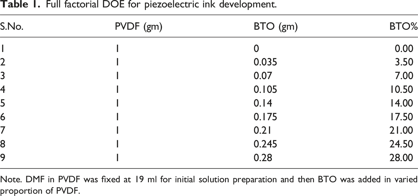
Note. DMF in PVDF was fixed at 19 ml for initial solution preparation and then BTO was added in varied proportion of PVDF.
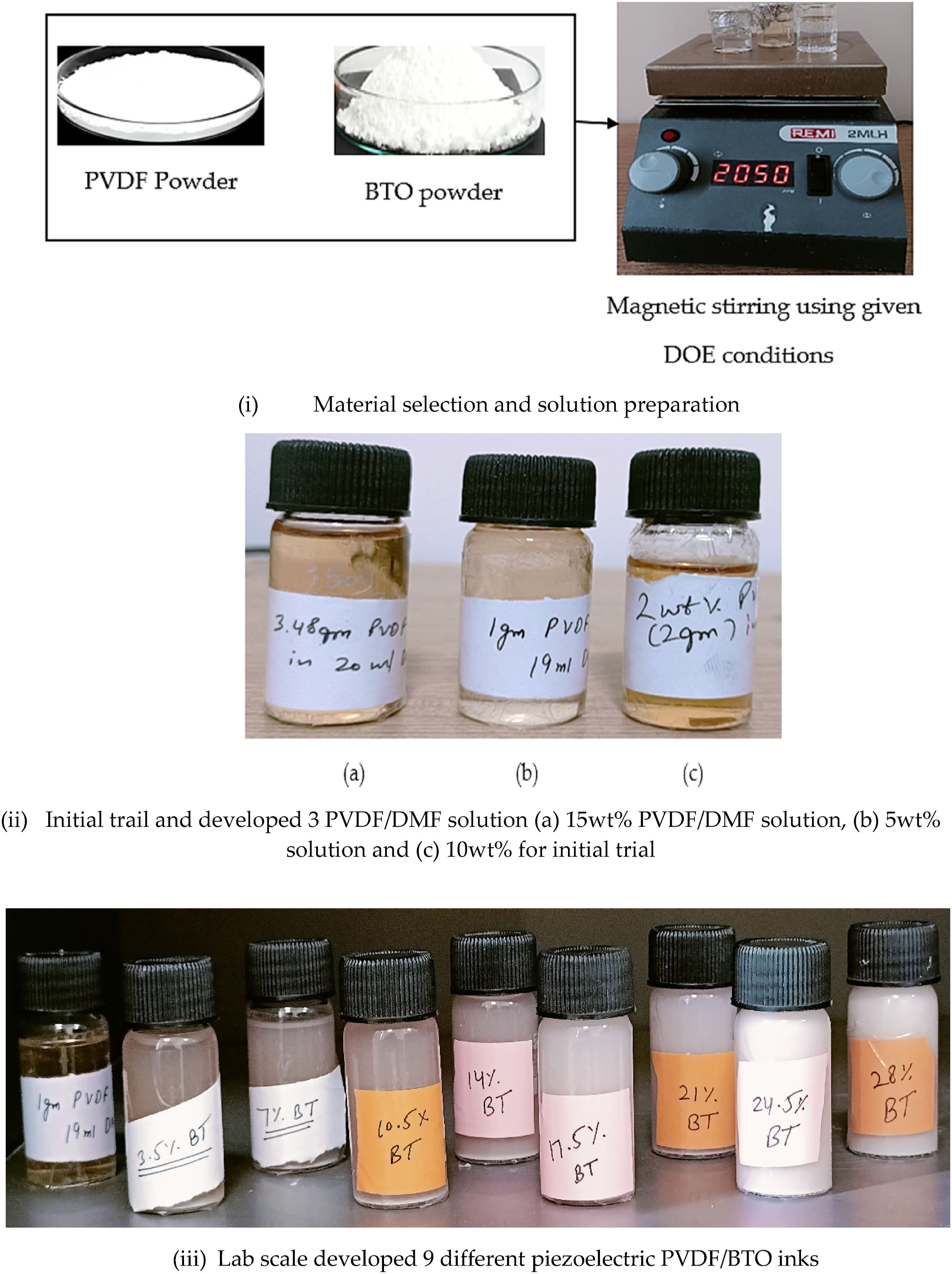
Different stages for ink development at lab scale.
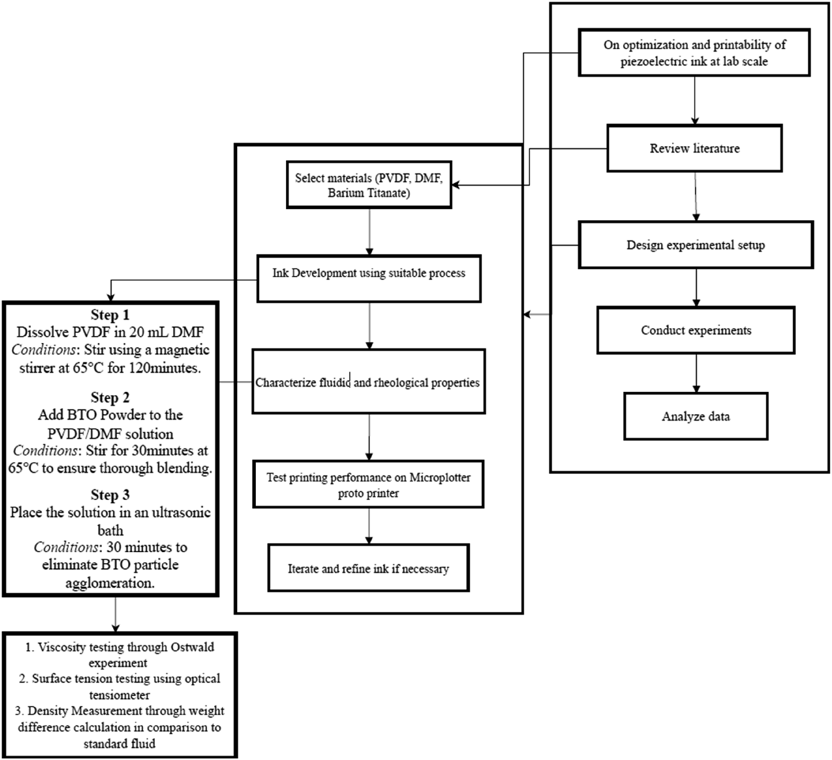
Process flow diagram for the current investigation.
Responses measured or output parameters for ink
Density measurement and calculations
The ink sample was processed for removing bubbles and impurities by ultrasonication of developed ink before usage. Each measurement required around 10 mL of ink. A cylindrical glass container with a capacity of 15 mL was used to test density. Before each measurement, the container was properly cleaned and dried to ensure that no contamination or residue affected the mass. An analytical balance was used to obtain the weight of the empty glass container which was referred to as Mcontainer. Next, 10 mL of the ink sample was put into the container using a graduated pipette. The container filled with the ink was then weighed again. The entire mass of the container and ink was recorded as Mcontainer + ink. Mass of the ink Mink is obtained by subtracting the empty container’s mass from the filled container. The density (ρ) of the ink was estimated using equation 1.
Kinematic viscosity measurement and calculations
The standard experiment used for kinematic viscosity testing was Ostwald viscometer. The Ostwald viscometer consists of a U-shaped glass tube with a narrow capillary section. For viscosity measurement water was used as a standard fluid. The device measures the time taken for a known volume of liquid to flow through a capillary tube under the influence of gravity. This time is proportional to the kinematic viscosity. Since viscosity is temperature-dependent, all sample inks were tested at 25°C. The flow time taken for the water and ink samples between two calibrated marks on the tube was measured. The standard values for viscosity and density for water were taken as 0.89 MPa.s and 997 kg/m3. Equation (2) has been used for viscosity calculation.
Surface tension and contact angle measurement
An optical tensiometer was used for surface tension calculation using shape analysis of drop fed through syringe type of arrangement. The instrument consists of high- definition camera for taking high-resolution images of a liquid drop. The captured images are processed by specialized software that analyses the shape of the droplet using pendant drop method when the drop is hanging from the needle. Figure 3 shows the tensiometer used in current study. Optical tensiometer for surface tension and contact angle measurement.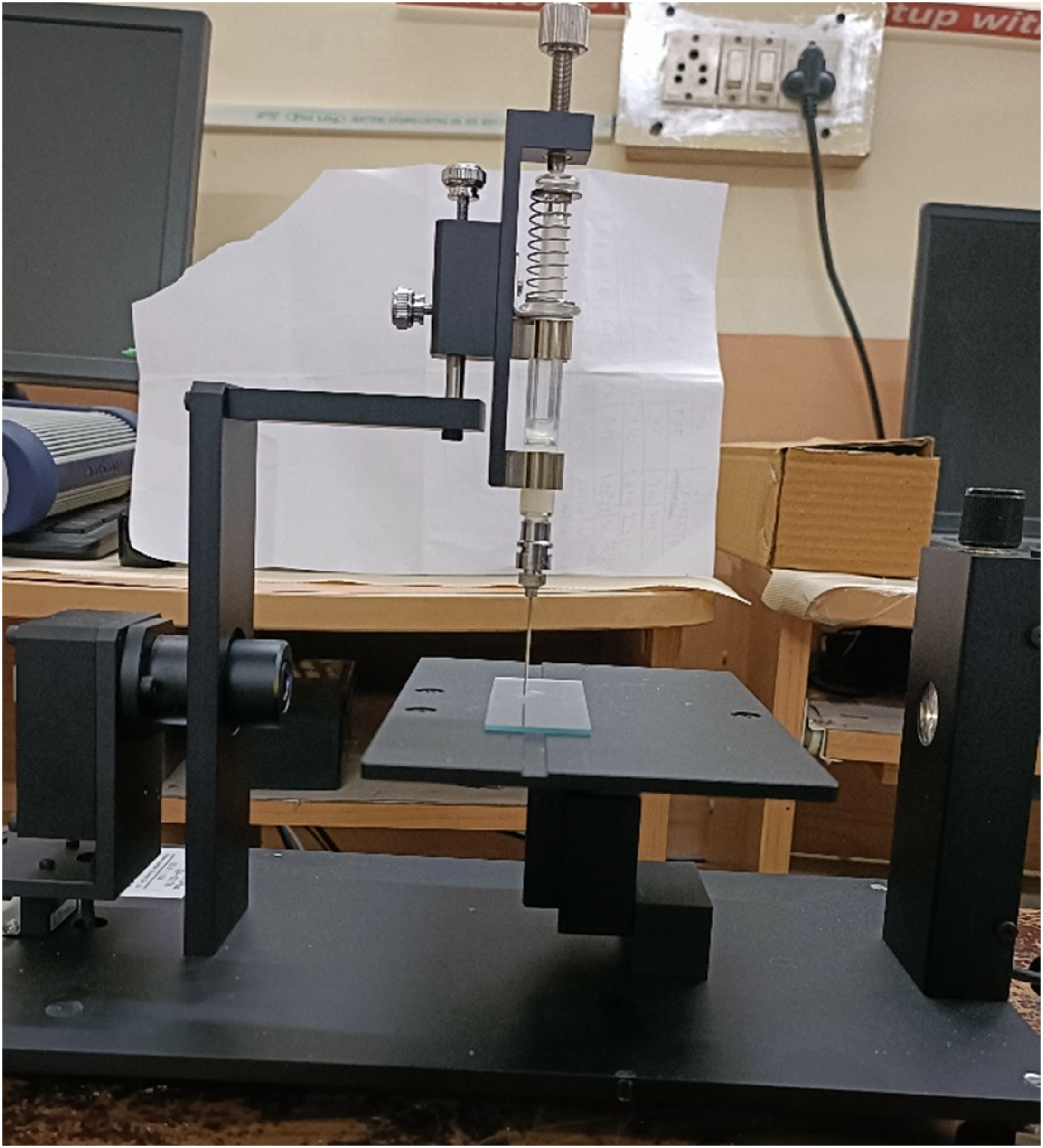
The optical tensiometer used for surface tension measurement was also used for contact angle measurement. The method used for contact angle measurement was the sessile drop method which calculated the contact angle when the droplet rests on a flat surface. For the contact angle measurement glass slides have been used as substrate for piezoelectric ink samples.
Printability of ink
After analyzing the rheological and fluidic behavior of the inks, the nine different formulated piezoelectric inks were tested for printability using a standard 2D printing device. The device used in the current study was Microplotter proto (Make: Sonoplot; Model: Proto). The inks were printed with standard dispensing conditions. Dispensing strength for printing the ink was 14.8 V, with dispensing frequency of 560.5 KHz. A standard capillary nozzle of 50 µm size was used for printing the formulated PVDF/BTO inks. Figure 4 shows the (a) Microplotter proto printer used in current study and (b) 2D design printed for ink testing. (a) Microplotter proto printer and (b) 2D design printed for ink testing.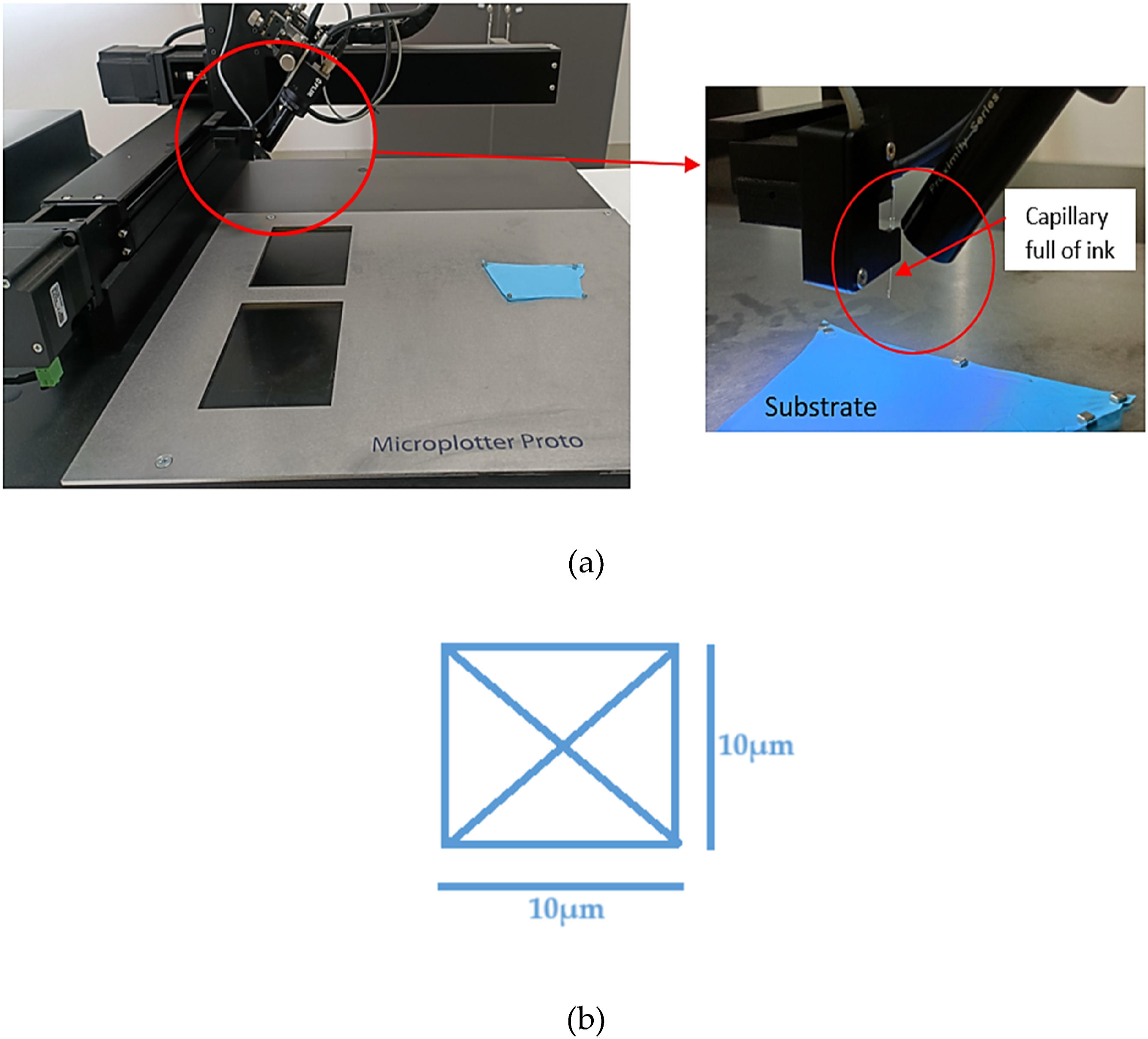
Result and discussion
Density result analysis
The developed inks were tested for density using weight difference techniques described in the methodology section. Figure 5 shows the density values for each variant of developed ink. The standard density value for BTO purchased through Sigma Aldrich was 6.08 gm/mL at 25°C, whereas the density for purchased PVDF powder and DMF solution was 1.74 gm/mL and 0.944 gm/mL respectively. The density rises slowly at first as the percentage of BTO is small (up to 7%), but as more BTO is added, the increase becomes more significant (especially after 14 wt%). Minimum and maximum density values of 988.30 kg/m3 and 1275.6 kg/m3 have been observed for ink sample 1 and sample nine respectively. This is because BTO, being much denser, has a more pronounced effect on the overall density at higher weight percentages. Rise in density values with increasing BTO content the ink is expected to behave like shear thickening liquid in static environment but shear thinning at high angular frequency when applied through piezoelectric current through capillary nozzle that may help in its easy dispensing on substrate. Shear-thinning helps the ink flow easily under the high shear rates experienced during the ejection or extrusion of ink. Once deposited, the ink becomes more viscous again, improving print quality and reducing spreading or dripping. Also, nanosized BTO particles exhibit high surface area and strong interparticle interactions, which influence their dispersion within the PVDF/DMF matrix. Well-dispersed nanoparticles contribute to a more homogeneous ink, thereby increasing the effective density due to the higher density of BTO compared to the PVDF/DMF solution. At the nanoscale, the properties of BTO particles deviate from their bulk counterparts due to quantum-size effects. These effects can influence the interaction between the nanoparticles and the surrounding polymer matrix, potentially altering the packing density and local structure of the ink. Density analysis for 9 variants of PVDF/BTO ink.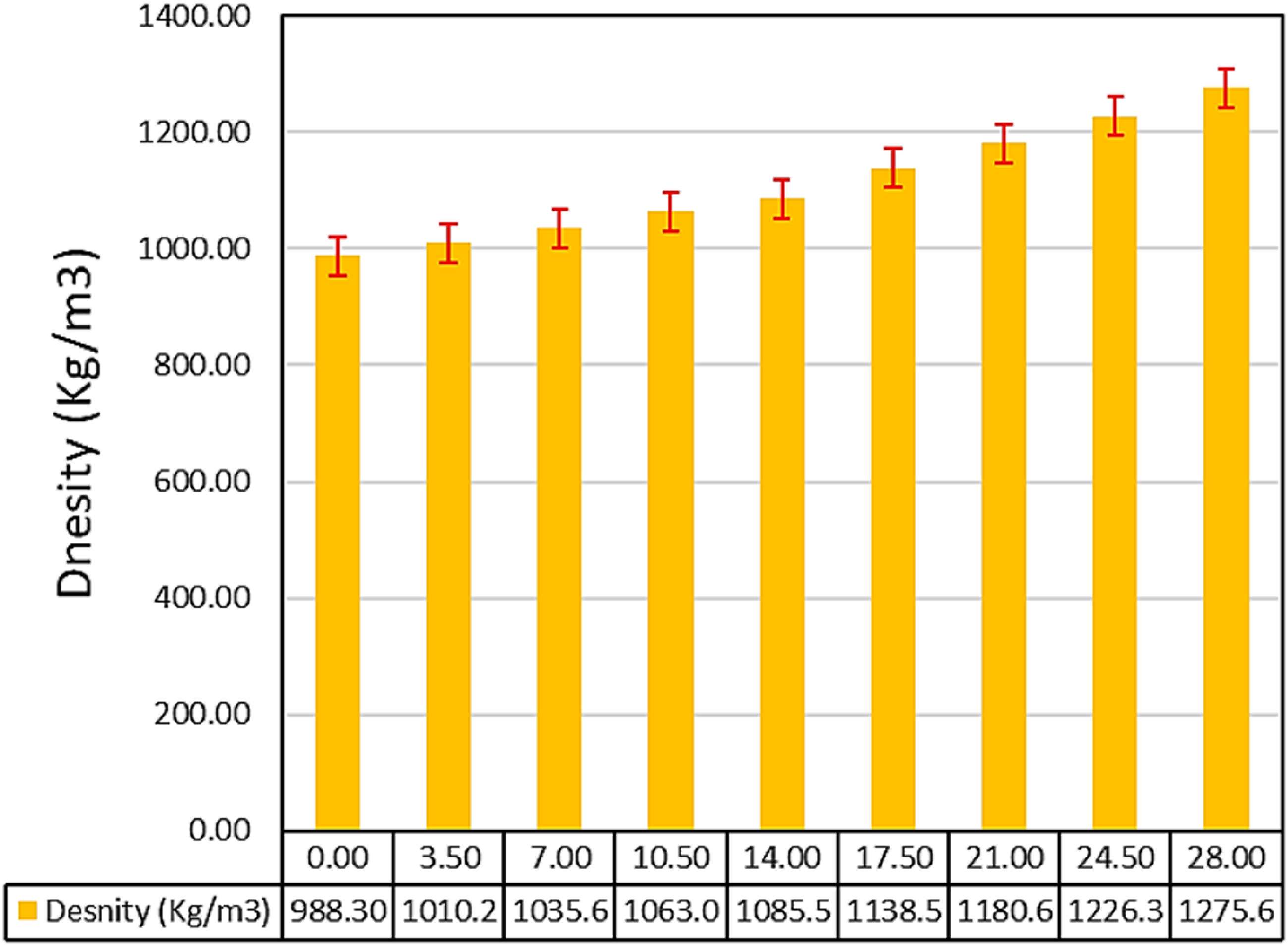
Viscosity result analysis
The developed ink samples were tested for viscosity using Ostwald viscometer setup. Figure 6 shows the (a) Ostwald setup for ink kinematic viscosity testing as well (b) observed viscosity for the increasing BTO content in PVDF/DMF mixture ratio. Maximum kinematic viscosity 57.65 has been observed for 28 wt% BTO in 5 wt% PVDF/DMF solution which was 1.41 times greater than the neat PVDF/DMFD solution-based ink. This may be due to the fact that BTO particles are capable of interacting with PVDF polymer inks thus increasing the viscosity of samples. The size of the BTO powder was less than 99 nm which may have resulted in high surface area that are more likely to interact with the PVDF chains. BTO particles in the solution interact with the PVDF polymer chains, providing flow resistance. The viscosity of the solution increased due to the presence of solid BTO particles, which hinder the movement of polymer chains. The results are well aligned with other studies. Agoudjil et al. 2008
46
observed viscosity for ethylene vinyl acetate (EVA)/BT composite and noted that for micro sized BT particles viscosity increases with increasing BT content in polymeric matrix. It has also been reported that for EVA based composite dynamic viscosity changes more significantly after 30% reinforcement level. Setup for viscosity testing and viscosity values for piezoelectric ink. (a) Surface tension for different samples and (b) contact angle values for lab scale developed inks.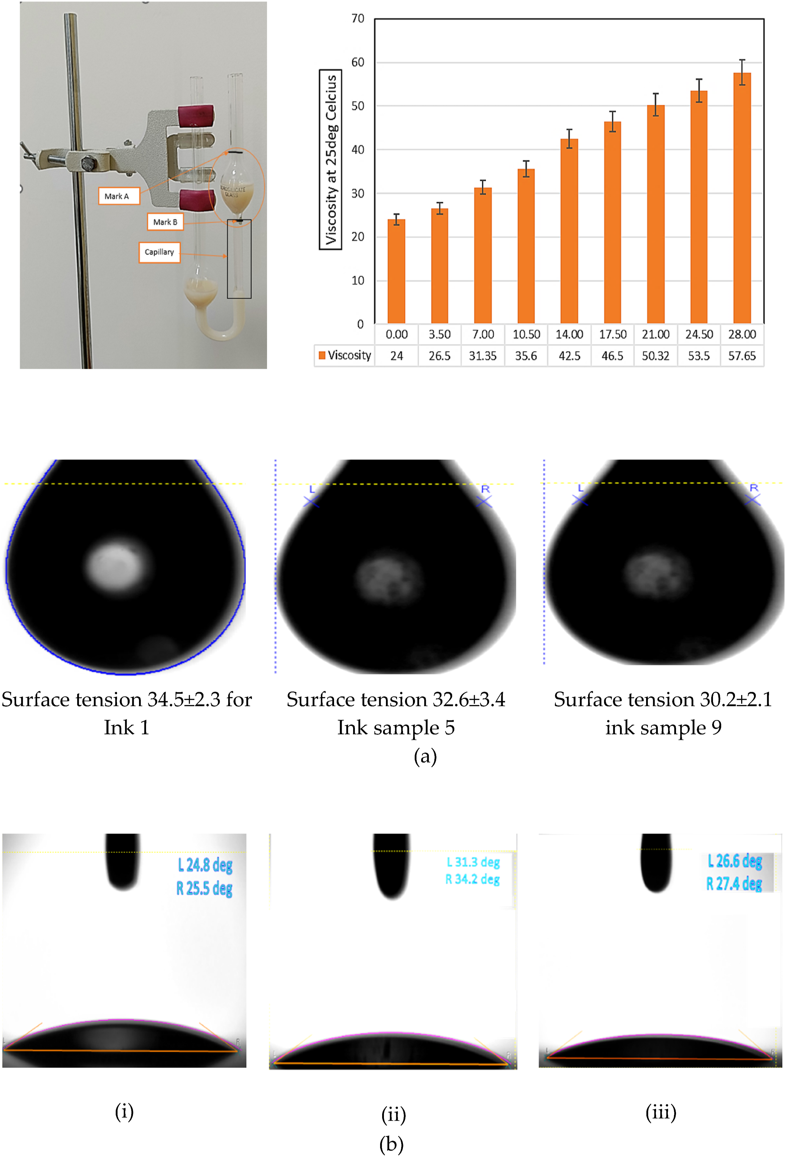
Surface tension and contact angle analysis
The tensiometer has been used for surface tension and contact angle measurement. Figure 7 shows the (a) surface tension and (b) contact angle values for the tested inks. It has been observed that with increased loading of BTO in PVDF/DMF solution the surface tension decreases marginally and it varied in range of 30.2 N/m for ink 9 to 34.5 N/m (give the tabular information about recorded surface tensions values). BTO nanoparticles when added to the PVDF/DMF solution, interfere with the cohesive forces between solvent molecules (DMF) and between PVDF chains. This disruption reduces the internal liquid-liquid interactions, causing the overall surface tension to decrease. Another potential reason for the fall in surface tension may be attributed to the tendency of BTO particles which tend to migrate toward the liquid-air interface, where they act similarly to surfactants. These particles diminish the cohesive forces among surface molecules, resulting in a decrease in surface tension. As the BTO concentration escalates, an accumulation of particles at the interface occurs, resulting in a further reduction in surface tension. At elevated BTO loadings of 21 to 28 wt%, a significant decrease in surface tension is not seen, perhaps because the system becomes saturated with particles, hence constraining future decreases in surface tension. Additionally, particle aggregation could start, reducing their effectiveness at the liquid-air interface. From the images of drop which were analyzed for surface tension calculation, it has also been observed that with higher BTO loading, less air entrapment occurred. This suggests the that the filler is well dispersed in the PVDF/DMF solution, preventing air from being trapped during the ink preparation or dispensing process. From the Figure 7(a)) (i-iii) it has been evident that the sphere size is reducing and more spherical image has been observed which suggests proper dispersion of BTO particles in PVDF/DMF solution with reduced surface tension. (a) Actual printing of developed ink and close view of nozzle and (b) successfully printed samples after solidification at room temperature (c) 2D printed samples as feasibility study. (d) XRD graph for sample S1 without BT reinforcement and S9 with 28 wt% BT in 5 wt%PVDF/DMF nano ink. (e) SEM micrograph at ×25 K magnification and analyzed image using image J software package tool.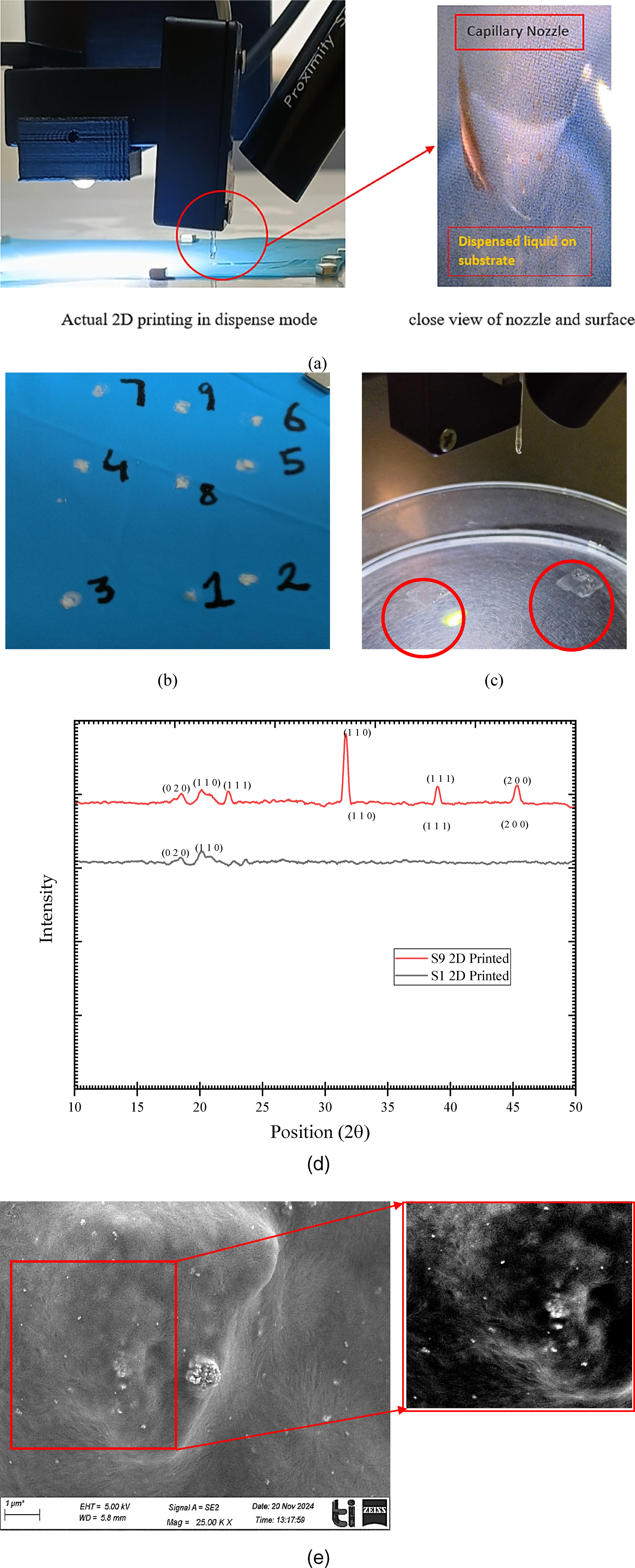
After surface tension, contact angle measurement has been performed on glass slide. It should be notes that contact angle is dependent on the substrate surface properties. For current study glass slides have been used as a common substrate for each ink. Contact angle measurement images clearly show that with increasing BTO content there has been significant increase in contact angle of samples. It implies that modification of the PVDF matrix with BTO at low concentrations can improve its hydrophobic property. The higher contact angle exhibited on the glass substrate was possibly due to high concentration of BTO which perhaps increased the surface roughness without necessarily altering the degree of wettability. It has been observed that sample 1 has shown contact angle of L24.8⁰ and R25.5⁰. The contact angle has increased upto L31.3⁰ and R34.2⁰ for sample 8. For sample nine the contact angle has been decreased again and has shown L26.6⁰ and R27.4⁰. The reason to this type of behavior may be attributed to the higher concentrations of BTO. The hydrophilic nature of BTO will become more dominant at higher concentration, especially in contact with the polar glass substrate. This can lead to improved wettability of the surface, causing the contact angle to decrease. The surface may become less hydrophobic as BTO disrupts the hydrophobic characteristics of PVDF. Figure 7(b)) show the contact angle for (i) sample 1, (ii) sample 8 (maximum) and (iii) sample 9.
Feasibility study for 2D printing on microplotter proto printer platform
The developed and analyzed inks were further examined for printability on Microplotter proto printer (Model: Proto; Make: Sonoplot). The used printer for 2D printing of ink was capable of printing ink of viscosity upto 450cp. The viscosity observed for developed ink were inside the capability range of printer. For 2D printing a square box of 10 µm × 10µ was used. A .dxf file was imported for the selected geometry and design. Other values such as dispensing strength and dispensing frequency was kept constant as 14.8 V and 560.5 KHz respectively. For the current study nozzle size of 50 µm has been used. From printability analysis it has been observed that the developed inks were printable through dispense mode. The previous literature suggests that high viscosity material leads to poor jetting behaviour and are not jettable.47–50 But all such studies have tested the piezoelectric ink on inkjet printer purely using jetting mode. It should be noted that in this research dispensing mode has been used rather than spraying mode which is a unique feature of the Microplotter proto printer. The printer takes ink into its nozzle by capillary action and dispense it using piezo signal of high frequency and voltage.
Thus, higher BTO loading in respect to PVDF with high viscosity (mention values) were successfully printed on nitrile surface without any hassle. Figure 7(a)) shows the actual printing with nozzle size of 50 µm and close view of nozzle which clearly shows that the ink was properly dispersed over the substrate surface. Figure 7(b)) shows the successfully printed square boxes after solidification at room temperature. Figure 7(c)) shows the 2D printed square design of 6*6 mm as a feasibility study on Microplotter proto printer platform. As the volume printed was quite low it took approximately 20 minutes for drying of sample.
This work is a precursor to the use of DIW micro plotter for printing thin wearable sensors using nano composite EAP ink. Such inks are expected to have higher densities and viscosity values due to presence of non-conducting nanofiller like BTO. This makes the micro plotting operation challenging as the Microplotter has limitation from the aspect of syringe size. The present study establishes that nano composite EAP based inks with significant loading of nano filler (upto 28%) can be easily employed on Microplotter.
The investigation led to successful trail of printing lab scale developed 5 wt% PVDF/BT ink on Microplotter printer platform. Although two major shortcomings are listed below. (a) The ink needs to be properly well mixed and shaken for better particle distribution otherwise if there will be significance difference between the ink preparation and printing then the reinforced particles will get settle down at base of ink bottle and only PVDF/DMF solution will be sucked through the nozzle. (b) High content of PVDF led to dense solution ultimately leading to poor capillary action. Thus, the 2D printing nozzle was not able to suck material using capillary action for highly dense PVDF ink. In this study we have checked for 5, 10 and 15wt% solution and we found only 5wt% solution can be effectively worked using 2D printing technique.
XRD processed data obtained through analysis.
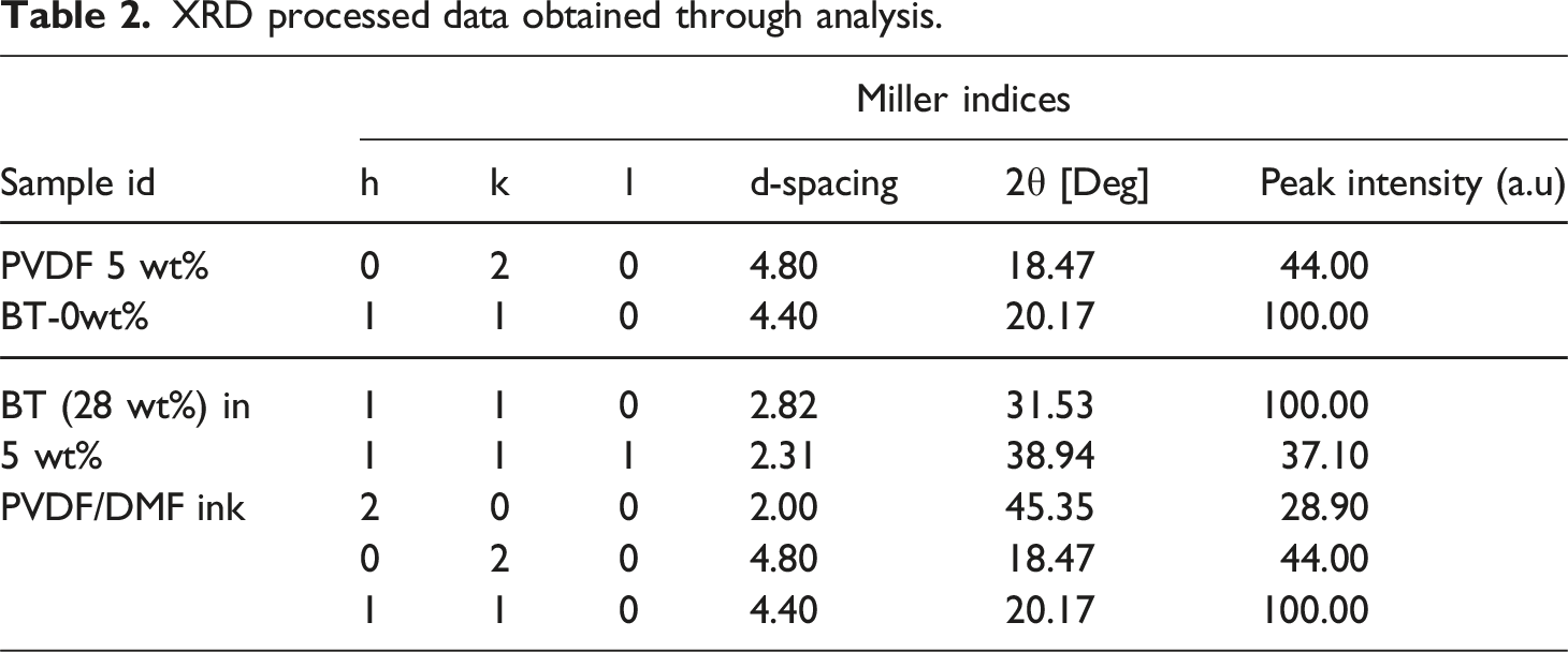
Similarly for nano dimensionality of BT reinforcement sample with highest weight percentage of BT checked for SEM characterization at ×25 K magnification. The taken photomicrograph was processed through image J software package tool for particle size calculation. From analysis it has been ascertained that the specimen had BT in the range of 13-17 nm thus confirming the nano dimensionality of BT in 2D printed PVDF/BT composite thin films. Figure 7(e)) shows the SEM micrographs for the 2D printed 28 wt% BT reinforced PVDF ink.
Conclusions
The current research work focused on printability and concentration optimization for PVDF ink reinforced with BTO nano particles. The study highlights different rheological and fluidic properties that are important for ink printing. Following are the key outcomes of this study. 1. From initial trials it may be concluded that 5wt% PVDF/DMF solution can work without having difficulty in nozzle ejection. 10 and 15wt% PVDF/DMF solution cannot be worked with dispense mode of printing due to high viscosity above 450cp. 2. From the different 9 inks developed through full factorial design it may be concluded that nano particle reinforcement of BTO upto 28wt% can be done in 5 wt% PVDF/DMF solution without any difficulty. Afterwards the BTO particle seems to be settling in PVDF solution and formed lumps and agglomeration has been observed. 3. From density and viscosity analysis it may be concluded that with increased BTO content all of the observed properties increased and maximum values for these properties for 28 wt% BTO reinforced PVDF/DMF solution observed to be 1275.6 kg/m3, 57.6cp. Whereas with high BTO content the surface tension above 24.5wt% decreased due to dominant nature of BTO at high concentration which is hydrophilic. 4. From printability study of lab scale developed inks, it may be concluded that the inks are printable on Microplotter proto printer platform in dispensing mode of printing. Thus, higher BTO reinforced PVDF/DMF matrix can be used in further studies for better electro mechanical properties especially for sensor development.
Footnotes
Acknowledgements
The authors are highly thankful towards the Thapar Institute of Engineering and technology for continuous motivation and technical support.
Declaration of conflicting interests
The author(s) declared no potential conflicts of interest with respect to the research, authorship, and/or publication of this article.
Funding
The author(s) disclosed receipt of the following financial support for the research, authorship, and/or publication of this article: The authors acknowledge the funding received from Indian government DST sponsored project file number DST/TDT/AM/2022/365 for preparation and other work related to experimentation and other works.