
Abstract
High-tension winding technology provides thermoplastic composite parts that can resist high centrifugal forces by applying radial compressive stresses. Based on the thick-walled cylinder theory of elastic mechanics and the principle of small deformation, mathematical model of the fiber stress distribution and radial compressive stress on the mandrel surface under the combined effects of tension and temperature field during the composite winding and molding process is established. A method for applying tensile forces to balance thermal stress is proposed. Results show that the thermal stress can reduce the relaxation effect of the inner layers of fibers during the winding process. With the increase in the number of winding layers under the three methods of tension application, namely, constant, constant torque, and taper tension, the fiber circumferential stress decreases layer by layer from the inside to the outside, while the radial compressive stress on the mandrel surface gradually increases. The equal stress tension provides the maximum radial compressive stress. When the stress per unit width of the fibers in each layer of the composite is 266.67 MPa, the radial compressive stress on the mandrel surface after 30 layers of winding is 15.52 MPa. The finite element simulation results show that the maximum error of composite circumferential stress and theoretical calculation is 6.7%, and the maximum error of radial compressive stress on the mandrel surface is 0.4%. These results verify the reliability of the mathematical model in this paper and provide theoretical support for the tension design in the high-tensile winding molding process of thermoplastic composite fibers.
Keywords
Introduction
Composite components such as energy storage flywheels, high-speed permanent magnet motor rotors, artillery body tubes and electromagnetic railgun body tubes, are subjected to extremely high centrifugal forces or internal pressures during operation, which can easily lead to separation of the composite structure.1–4 To inhibit composite failure under operating conditions and maintain the safety and efficiency of the component, sufficient compressive stresses need to be pre-applied at the time of manufacture to counteract the tensile stresses due to centrifugal force and internal pressure to ensure structural integrity. Two prestressing methods are as follows: one method aims to provide prestressing by overfitting on the exterior of the member through press-fitting and other methods; the other is to use high-tension winding technology to realize high prestressing fabrication. The interference assembly method has precise control. However, large-size components encounter difficulties in their implementation and are easily damaged, and their structures are easily overweighted. Meanwhile, fiber winding technology is characterized by its high production efficiency, high designability of prestress, light weight, and high strength, making it a hotspot for the development of high prestressing manufacturing technology.5–7
A common method of prestressing application at present is realized by press-fit assembly of thermoset composite members and metal parts. 8 Deng et al. 9 analyzed the residual stresses during the entire winding-curing process of the wound structures, and characterized the internal residual stress distribution after curing by measuring the rebound deformation and the internal and external surface strain changes. Lee et al. 10 proposed a design methodology for a composite permanent magnet motor with an electric turbocharger, which was analyzed in terms of dynamics and rotor response considering stress sources such as press-fit assembly and centrifugal force and experimentally assembled with a 1.6 L diesel engine. The results show a 49.14% reduction in the time it takes for the engine to reach its rated boost pressure using this motor. Eduljee et al. 11 studied the elastic response of composite cylindrical structures under the influence of thermal fields and tensile forces, and calculated the stress distribution after the removal of the mandrel. Lamontia et al. 12 studied the stress concentration and mechanical properties of composite shells under tensile forces by the finite element method. Wang et al. 13 summarized thermoset composite sleeve stress design and preparation in terms of sleeve material, stress design, prestress preparation and testing. Xu et al. 14 investigated eddy current losses in composite sheaths installed via press-fit and used various methods to minimize eddy currents. Kale et al. 15 compared the energy storage performance of metal and composite flywheels and concluded that composite flywheels have a higher energy efficiency ratio. Skinner et al. 16 developed a computational algorithm based on accepted analytical models for investigating the viscoelastic behavior of carbon fiber reinforced polymer composite flywheel rotors assembled by press-fitting an aluminum hub and evaluating the flywheel rotor failure using the Tsai–Wu failure criterion. Qu et al. 17 developed a finite element analysis model of a composite rim and metal hub assembled by press-fitting to simulate and analyze the stress distribution of the rotor.
Overall, the application method of prestressing by press-fit assembly can cause damage to composite members during assembly, while the amount of overstress in press-fit assembly cannot be precisely controlled. Simultaneously, thermosetting resins must be heated to cure after winding is completed, and excessive temperatures can cause damage to the mandrel, for example, the permanent magnets of permanent magnet motors will lose their magnetic properties at high temperatures. Thermoplastic composites can substantially reduce the resin flow relaxation by local phase change during in situ molding, and the efficiency of converting tension into prestress is high. Therefore, the ideal tension preload effect can be realized with a small winding thickness.18–21 In this paper, the high-tension winding process of thermoplastic composites is investigated, and the stress distribution of composites under tension during the winding process is analyzed. Based on the thick-walled cylinder theory of elastic mechanics and the principle of small deformation, mathematical models of fiber stress distribution and radial compressive stress are established on the mandrel surface under high tension during the winding process of composite materials. The winding tension determined by the initial tension and preset stress is also designed, and the stress distribution in each layer of the composite and the radial compressive stress on the mandrel surface are analyzed under different winding tensions. The theoretical calculation results are compared with the finite element simulation calculations, revealing that the error is within the acceptable range, which verifies the accuracy of the mathematical model.
Mechanical analytical modeling
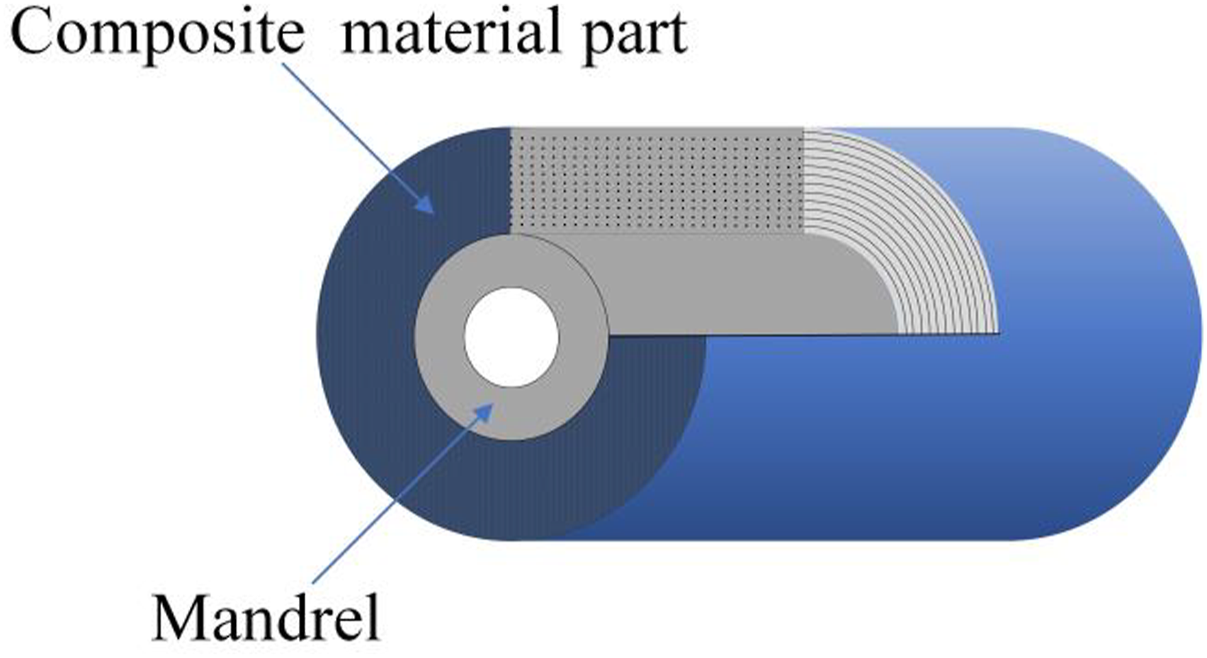
The winding of a composite member containing a mandrel is a process involving continuous changes in stress state during the winding process. During the winding process, the outermost fibers affect the stress distribution of the inner fibers and the mandrel. The mathematical model of stress distribution in composites in this paper is based on the following assumptions (Figure 1): (1) The fibers of each layer of the composite are in the elastic range; (2) In the winding process under tension, each fiber layer is equated to a superposition of a thin ring of pre-stressed composites containing pre-stress. The winding process is simplified as a plane stress problem, and the axial stress component is neglected; (3) The composite material layers are in close contact with each other, the radial displacement is continuous, and no relative sliding occurs in the ring direction; the influence of friction is also overlooked; (4) The change in monolayer thickness is also neglected due to resin flow and phase change during the winding process. (5) The heating and cooling processes of the composite material are completed instantaneously. Schematic structure of thermoplastic composite winding member.
Mandrel stresses
Figure 2 shows the force analysis of the mandrel and composite layer for the high-tension winding process. a and b denote the inner and outer diameters of the mandrel, respectively, Force analysis of mandrel and composite layer during winding process.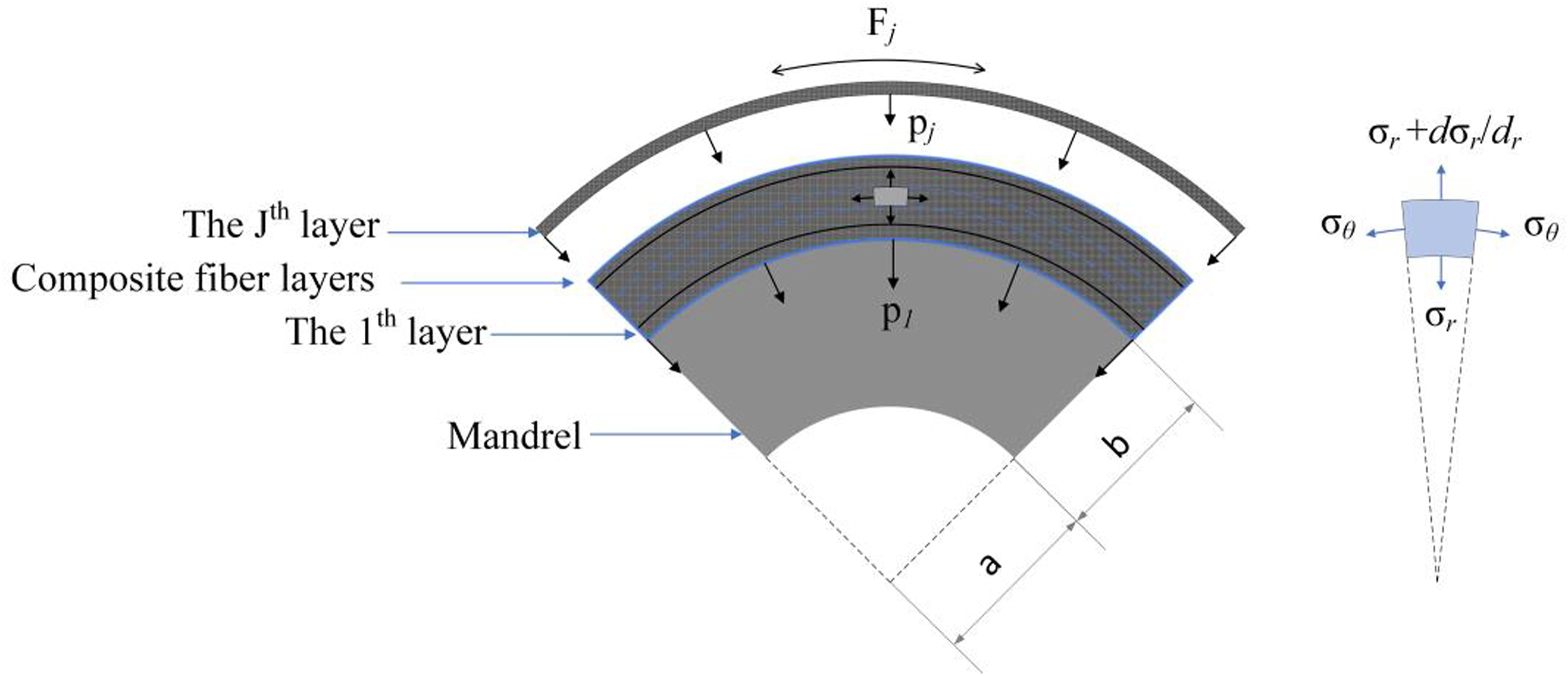
According to the principle of elastic mechanics, under axisymmetric loading, the microelement of the mandrel and the composite layers satisfy the following equilibrium equations:

The variable with the symbol “m” is defined as the variable associated with the mandrel. For an isotropic metal mandrel, the relationship between stress and strain can be expressed as follows:
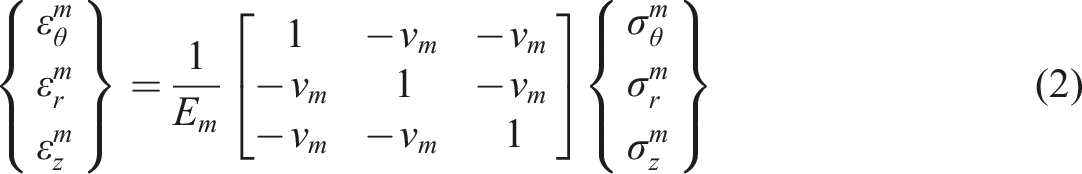
The stress and strain of the mandrel are regarded as the stress and strain in the plane without considering those in the axial direction. According to the theory of small deformation, the strain and displacement of the mandrel are satisfied as shown below:

Combining equations (2) and (3), the following equation can be obtained:
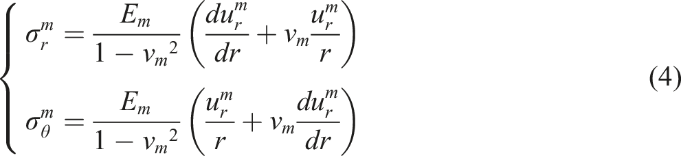
Equation (4) is substituted into the equilibrium equation (1). The generalized solution for the core mode displacement can be obtained by solving the differential equation:

Based on the force analysis diagram of the mandrel, boundary conditions are determined as follows:

Substituting equations (6) into (5), the generalization coefficient can be expressed as:
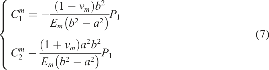
Combining equations (5) and (7) and substituting them into equation (4), the displacement and stress distribution of the mandrel can be expressed as follows:
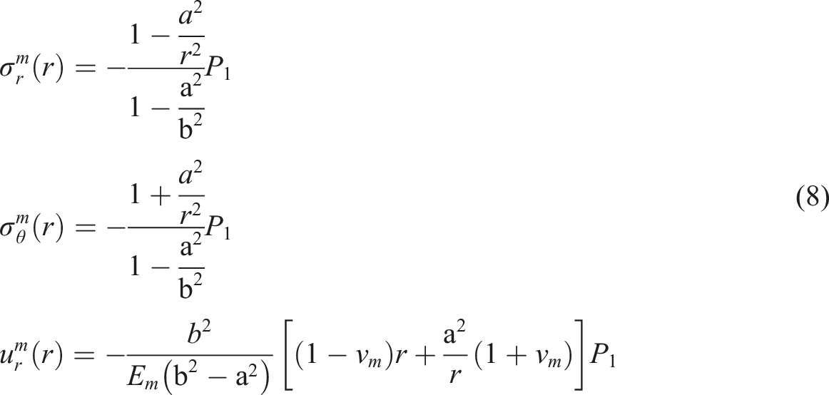
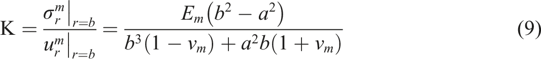
The radial generalized stiffness
Composite stress
The fiber composites satisfy the orthogonal anisotropic three-dimensional principal relationship. Therefore, the strain in the composite layer can be expressed as follows:
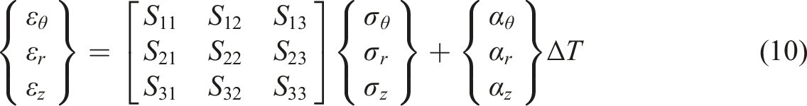
Similar to the mandrel, the axial stress and strain of the composite material are not considered, and the radial displacement and strain of the composite material satisfy the following conditions in the case of small deformation:

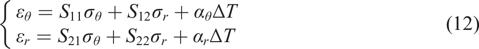
Combining equations (11) and (12), the expressions for the circumferential and radial stresses can be obtained:
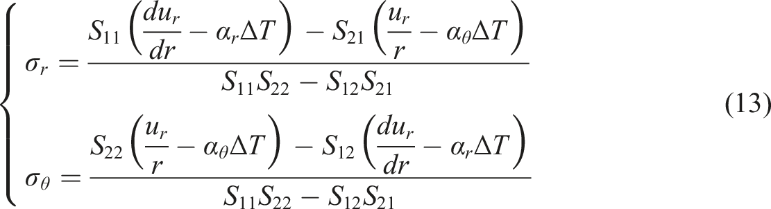
Substituting equation (13) into equation (1), the differential equation for radial displacement can be obtained as:

This differential equation is solved to obtain its generalized solution as:

Substituting the radial displacement generalization of equation (15) into equation (13), the stress expression for the composite is obtained as:

The close adherence of the outer surface of the mandrel to the composite material is assumed during the winding process. Thus, the radial displacement and stress on the contact surface satisfy the continuity condition. When winding to a fiber layer radius of
Where,
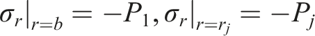
The boundary conditions for the inner and outer walls of the composite are given by the following equations:
The mandrel and the composite material satisfy the following continuity conditions at radius

Combining the above continuity conditions and the mandrel radial stiffness equation (9), the boundary conditions for the inner and outer walls of the composite layer can be expressed as:
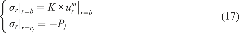
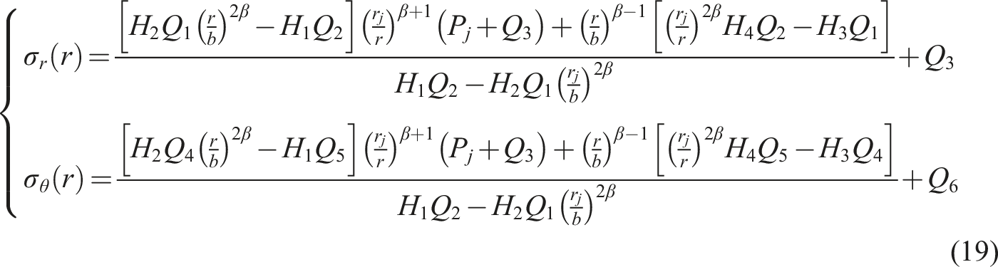
Substituting equation (17) into equation (16), the generalized coefficients of the system of equations can be solved:
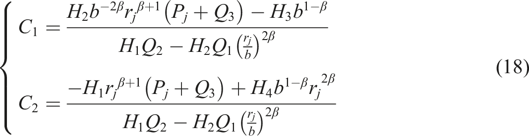
Substituting equation (18) into equation (16), the radial and circumferential stresses in each layer of the composite can be obtained as follows:
Stress after winding completion
The composite layer in this paper is a small deformation, and the tension acting on the composite layer is within the elastic limit of the fiber. This condition is in accordance with the principle of elastic superposition. Therefore, at the end of winding the jth layer, the winding radius is
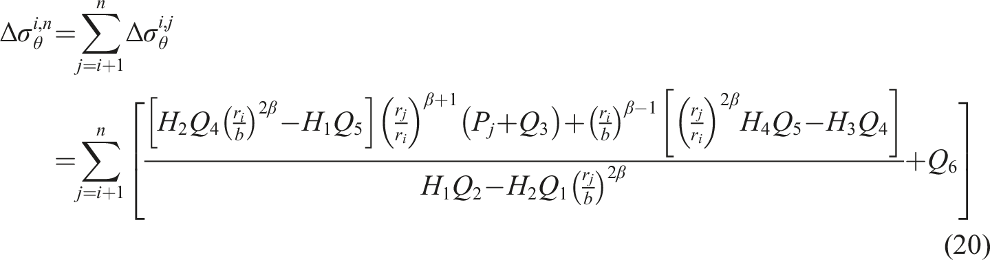
Assuming that heating and cooling are completed instantaneously, equation (20) simultaneously applies to both the heating and cooling processes of the composite material. The circumferential residual stress of the

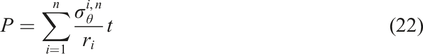
The composite layer must provide a large compressive force on the outer surface of the mandrel to overcome the centrifugal action or internal pressure of the composite member under operating conditions. This force can be measured by the radial pressure of the composite layer on the mandrel. The radial compressive stress of the composite material on the mandrel is obtained from the circumferential stress of each layer of the composite material after winding completion
23
:
Tension design for the fiber winding process
The current tension application methods in practical production applications can be divided into two categories: (1) determining the change rule of the initial winding tension and calculating the stress distribution of the composite material after the completion of the winding; and (2) setting the stress distribution of each layer of the composite material to obtain the inverse of the application of the winding tension.
Determination by the initial value of tension
When the initial tension is determined, common winding tensions include the following three forms 21 :
Constant tension:

Constant torque tension:
Taper tension:
Figure 3 shows the variation of winding tension when Winding tension determined from the initial tension.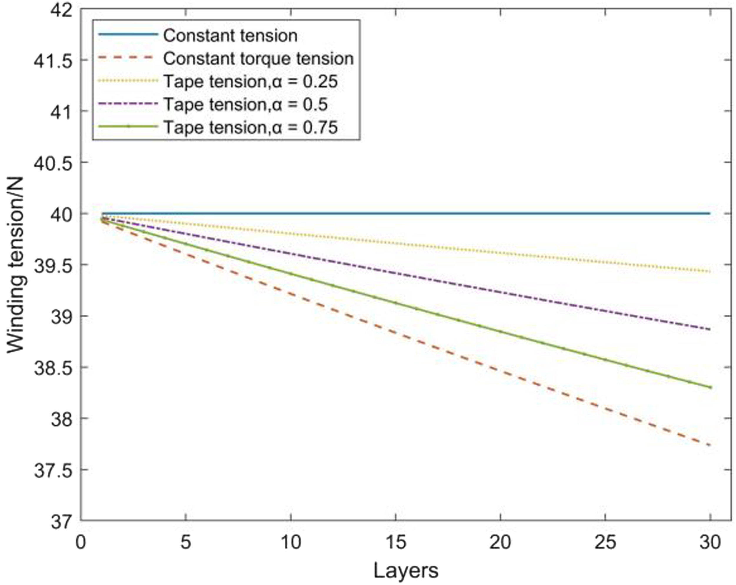
Determined by stress preset value
In the composite winding process, a tension application method for equal stress winding is available.
24
The tension is reduced layer by layer with the winding by controlling the winding tension, and the circumferential stress of each layer of the composite material reaches the state of uniform distribution after the completion of the winding. The tension calculation process is shown in Figure 4. Flowchart of the tension solving process.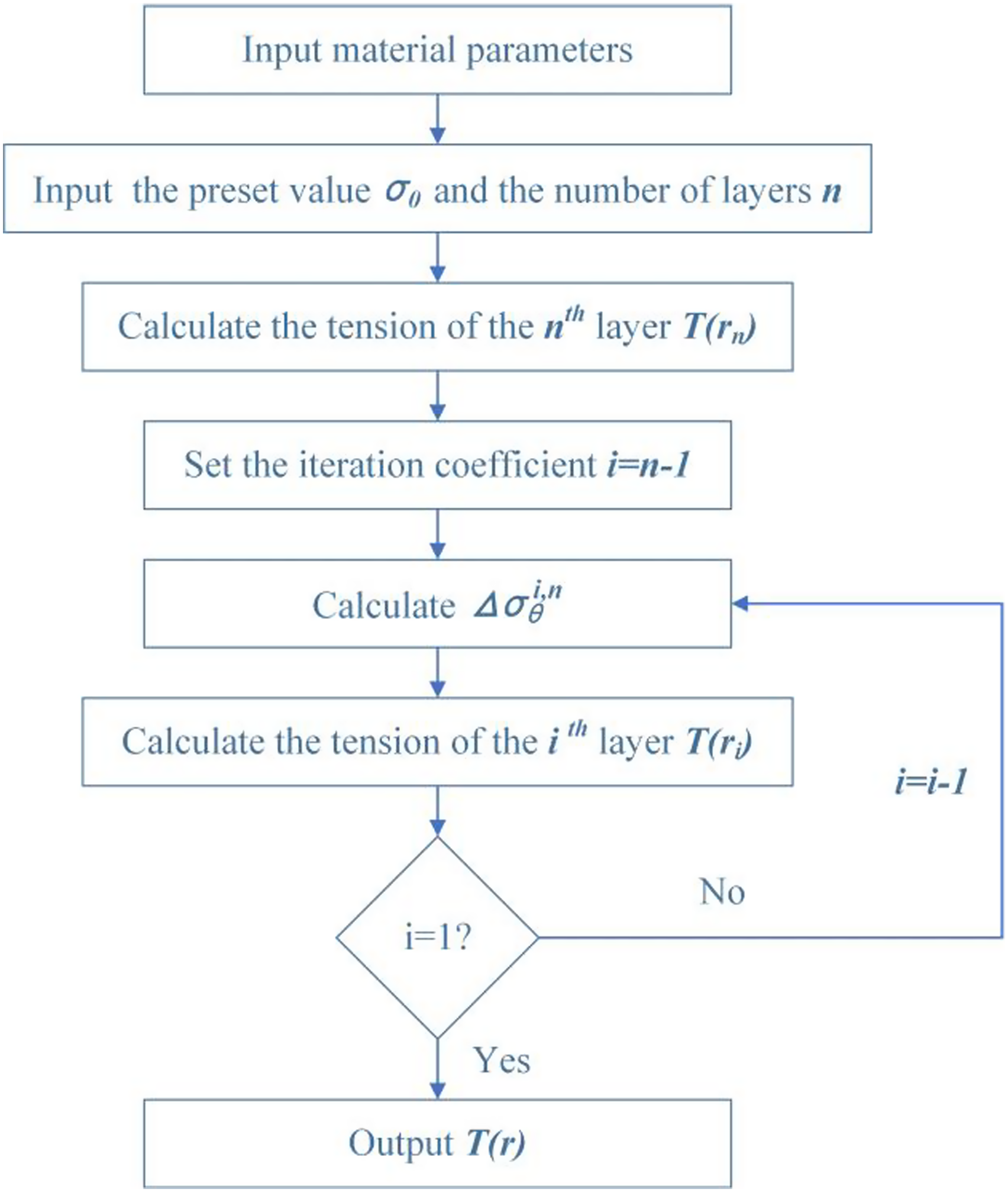
Let the value of the circumferential stress to the left of the equal sign in equation (21) be the preset value
Figure 5 shows the tension applied during the winding process when the circumferential stress in each layer of the composite is maintained at the present value Winding tension determined by the set stress value 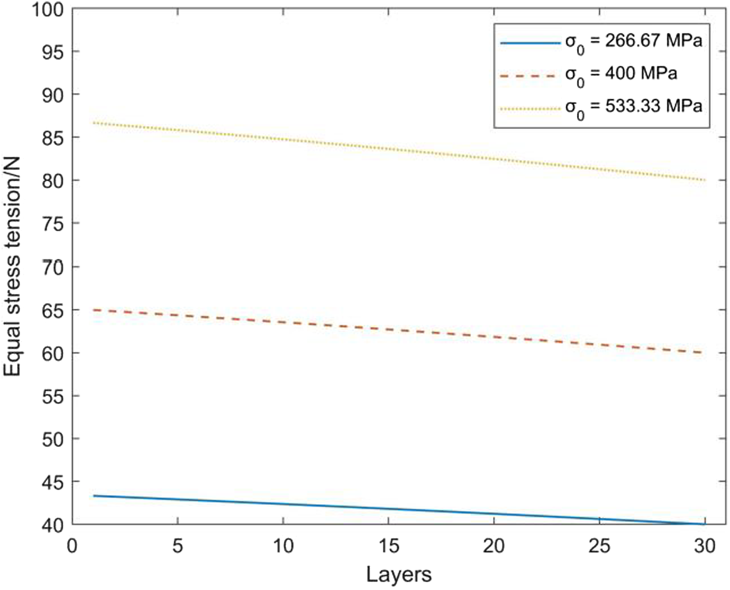
Results and discussion
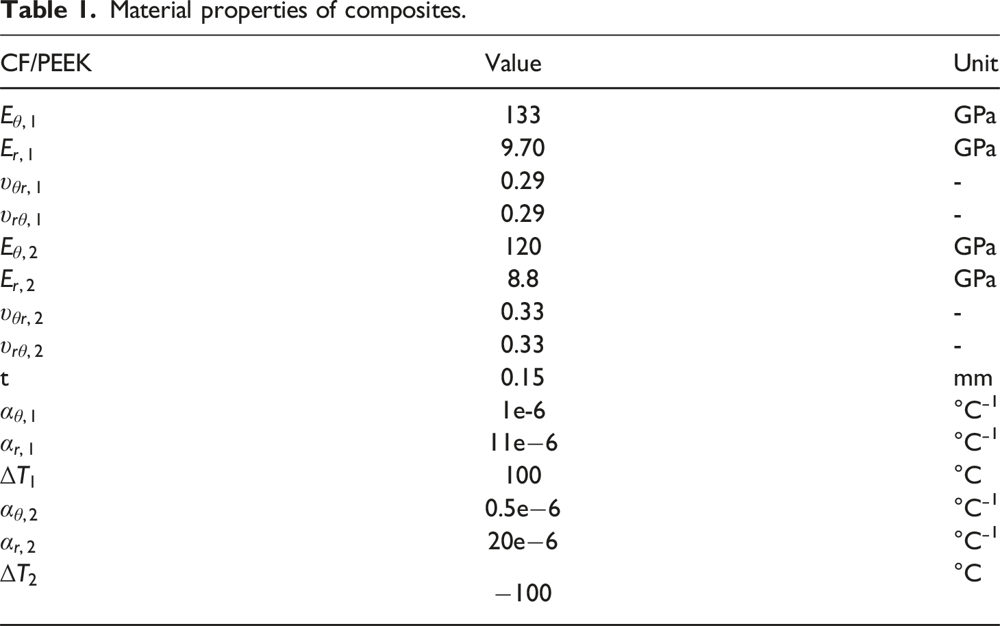
Material properties of composites.
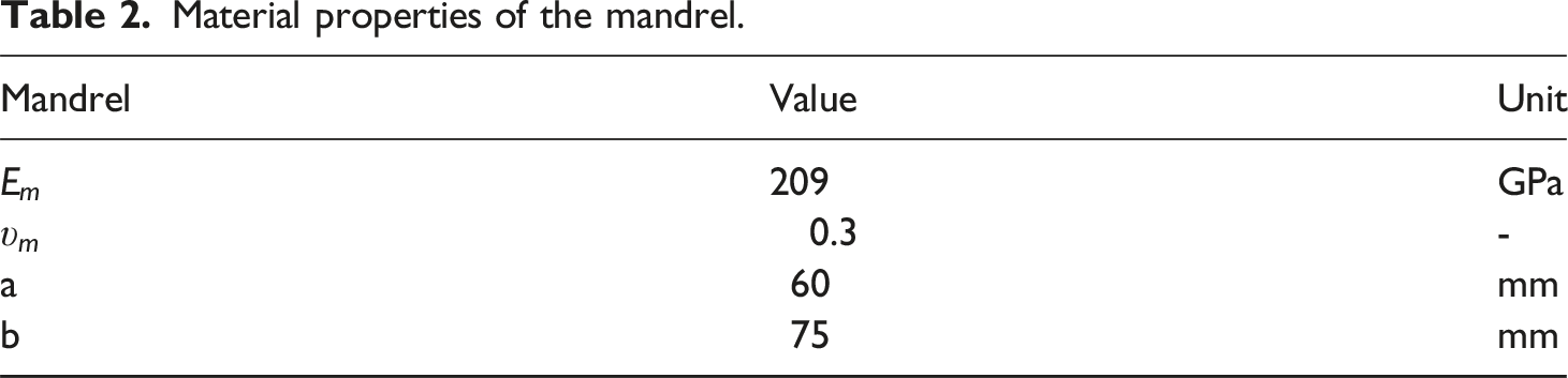
Material properties of the mandrel.
The effects of tension and temperature field
According to equation (21), assuming the effect of tension is removed, after winding 30 layers, the circumferential stress in the first layer is only 1.54 MPa, which is several orders of magnitude lower than the tension applied in high-tension winding. Therefore, to analyze the influence of tension and the temperature field on the stress distribution and mandrel surface pressure, in this section, we scale the tension value and apply a constant tension of
Figure 6(a) shows the distribution of the circumferential stress in each layer after the winding process is completed. For convenience in discussion, the winding process is described based on the loading conditions of the winding. When the load is The effects of tension and temperature field (a) circumferential stress; (b) radial compressive stress.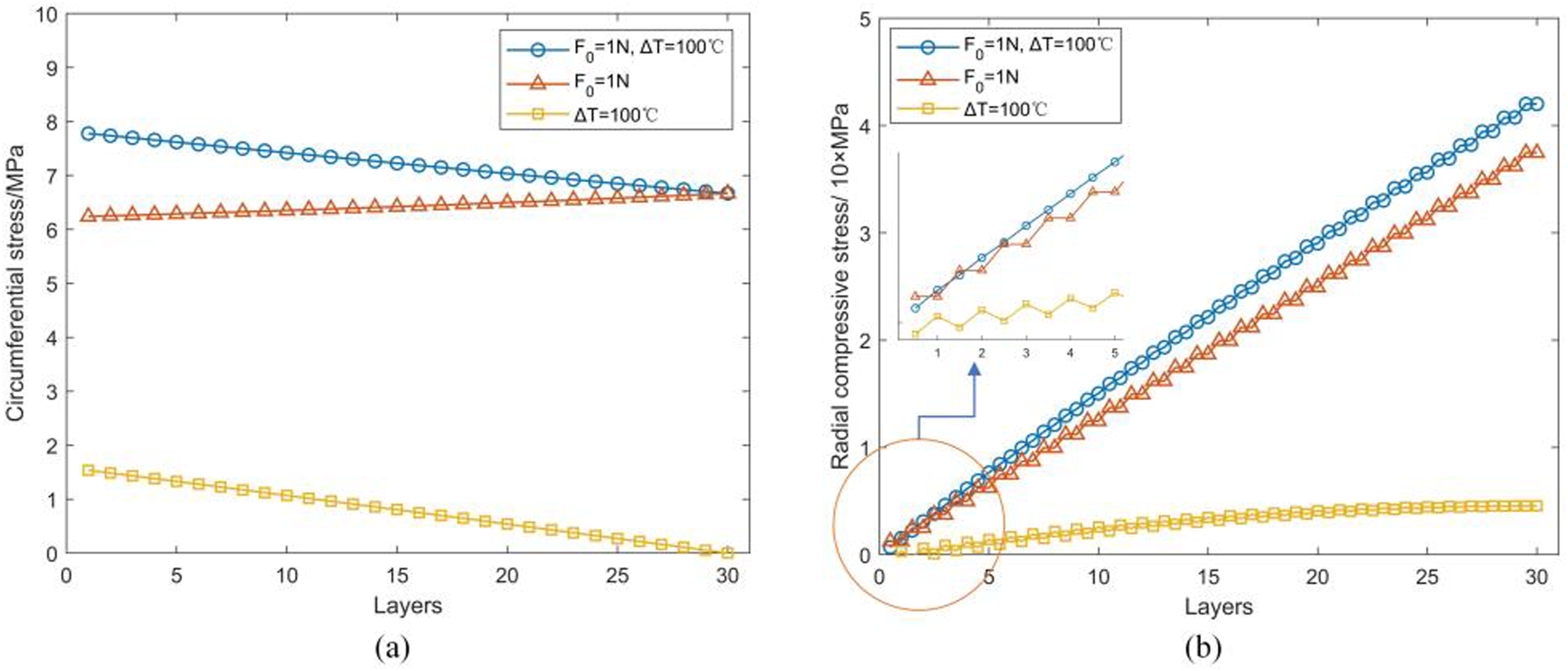
Although the variation in the temperature field causes circumferential stress in the composite material, its impact is not significant for the applied tension value in the high-tension winding process. Therefore, the following discussion focus on the effect of tension, while neglecting the effect of temperature field variations.
Stress distribution
The stresses in each layer of the composite are analyzed with Stress distribution (a) circumferential stress at 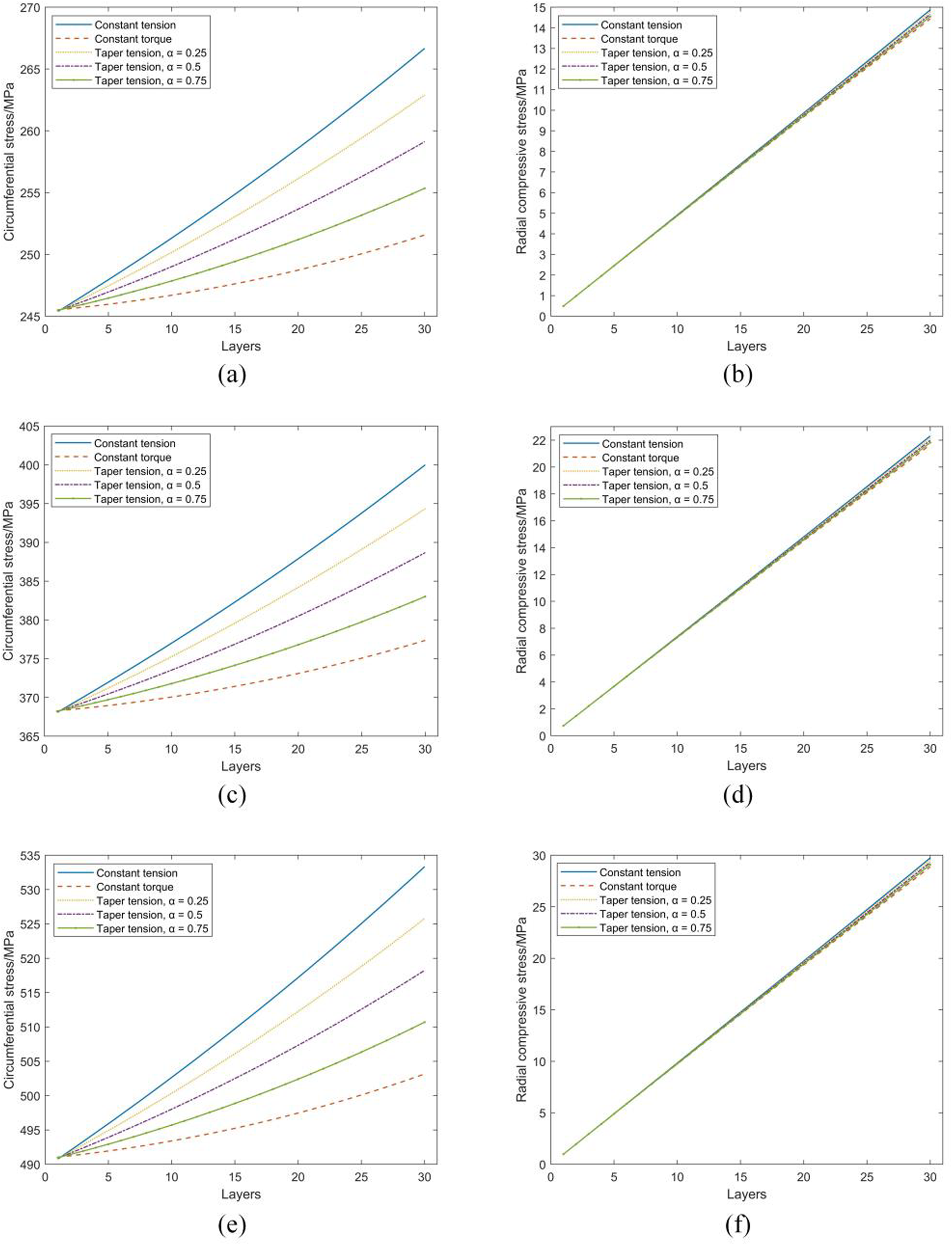
Comparing Figure 7(a), (c), (e) and (b), (d), (f), as the initial tension
Thus, a small taper coefficient indicates its closeness to constant tension winding. With the progression of winding, the tension of equal torque winding gradually decreases, leading to a gradual reduction in the value of its effect on the circumferential stresses on the inner fibers. However, the best compression of the composites on the surface of the mandrel is realized by constant tension winding with a value of 14.87 MPa, while constant torque winding has a poor compression effect with a value of 14.44 MPa. The compression effect of winding with taper tension is observed in the middle of the range between constant tension and constant torque winding. A small taper factor indicates the closeness of the compression effect to constant tension winding.
For the winding tension control method with a given preset value of Radial compressive stress on the surface of the mandrel at the end of equal stress winding.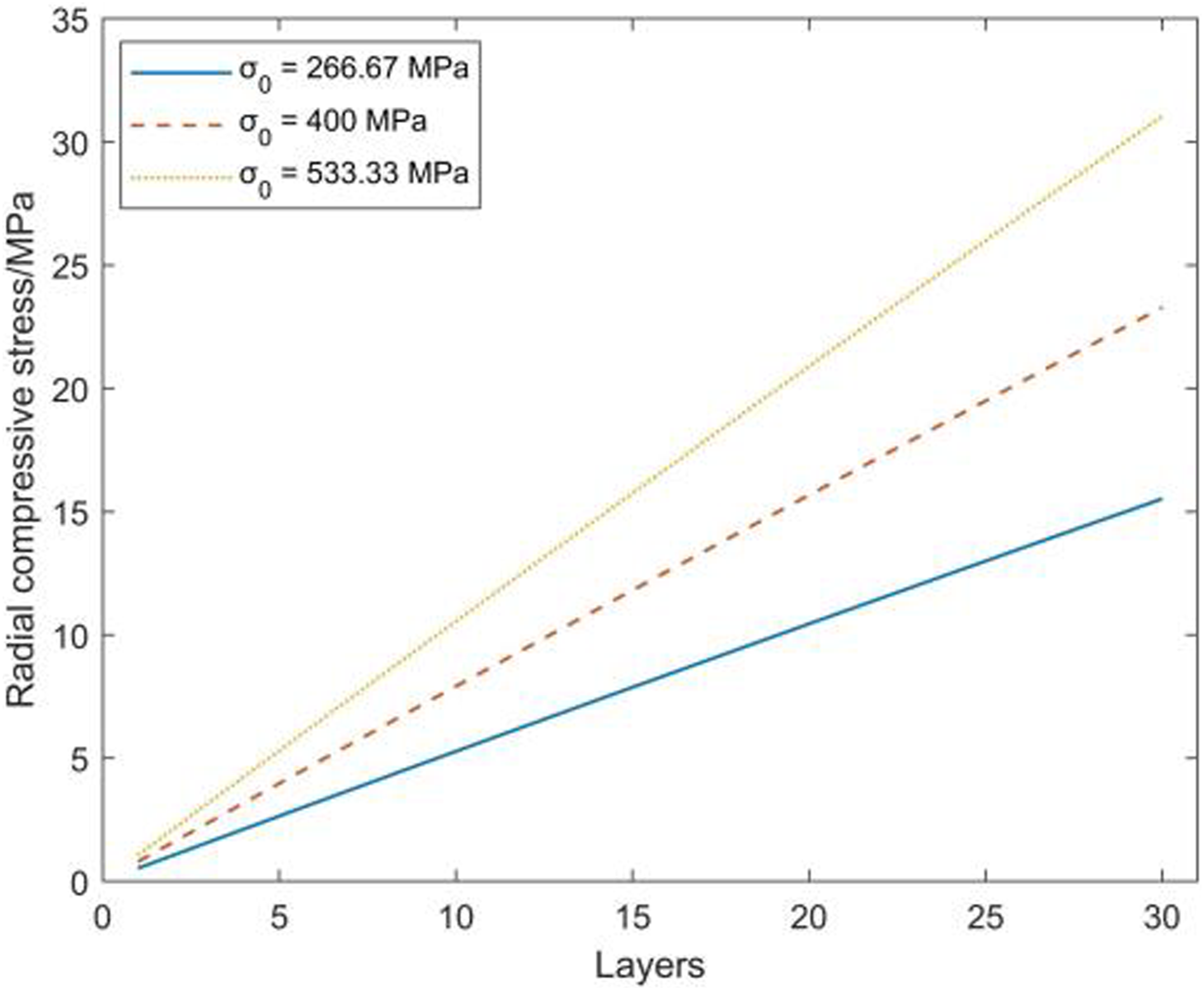
Finite element simulation comparison
ABAQUS is used to perform a finite element simulation of the composite winding process and compare the results with theoretical calculations to verify the accuracy of the analytical results. The role of tension in the winding process is equated with the application of a temperature field. The finite element simulation model is simplified to facilitate the calculation, and a 1/4 finite element model is established. Simultaneously, the three composite layers are regarded as one layer, and the composite material is divided into 10 layers to simulate the winding process layer by layer. The thickness of each layer is 0.45 mm. The mandrel is modeled using C3D8I elements, the composite layers are modeled using C3D8R elements, and surface-to-surface contact is employed. In the finite element simulation, the effect of tension can be equivalently represented by the variation of the temperature field. 25 The layer-by-layer winding simulation is achieved using the model change function in ABAQUS. In the initial analysis step, all composite layers are set to an inactive state, and in each subsequent analysis step, the composite layers and thermal loads are activated layer by layer.
Finite element simulations of the winding process are also performed for constant tension, constant torque tension, taper tension (α = 0.5) at the initial winding tension Simulation results of circumferential stress distribution (a) constant tension; (b) constant torque tension; (c) taper tension (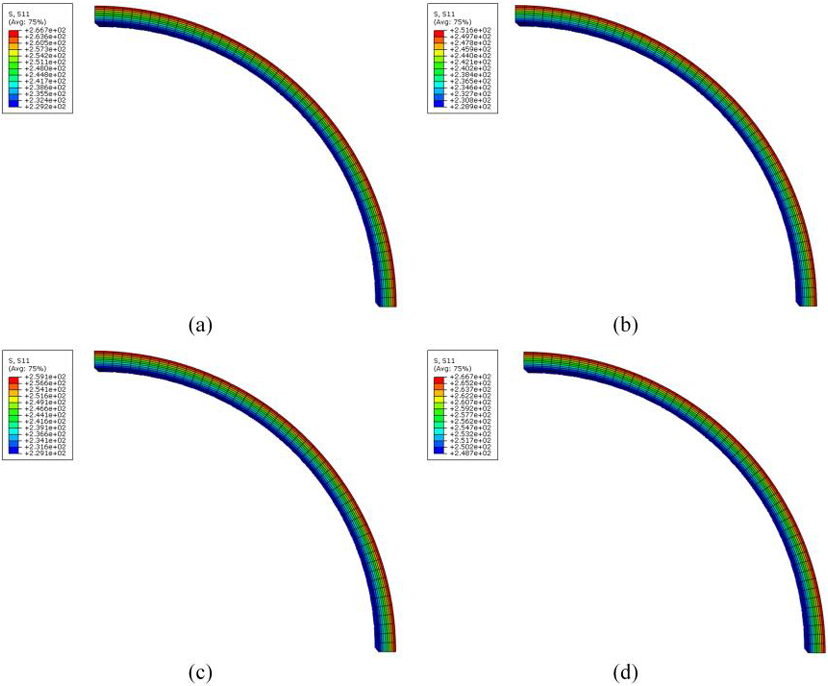
The circumferential stress distribution of constant tension winding calculated by finite element simulation is 229.29–266.67 MPa, and the theoretically calculated value is 245.38–266.67 MPa with a maximum error of 6.6%. Figure 10 shows the error of circumferential stress for constant tension winding. The circumferential stress distribution of constant torque winding is 228.96–251.57 MPa, and the theoretically calculated value is 245.52–251.57 MPa with a maximum error of 6.7%. The circumferential stress distribution of taper tension winding is 229.07–259.12 MPa, and the theoretically calculated value is 245.45–259.12 MPa, revealing a maximum error of 6.7% for each layer. The circumferential stress distribution of equal stress winding is 248.72–266.67 MPa, and the theoretically calculated value should be 266.67 MPa for all layers with a maximum error of 6.7%. Circumferential stress distribution error in constant tension winding.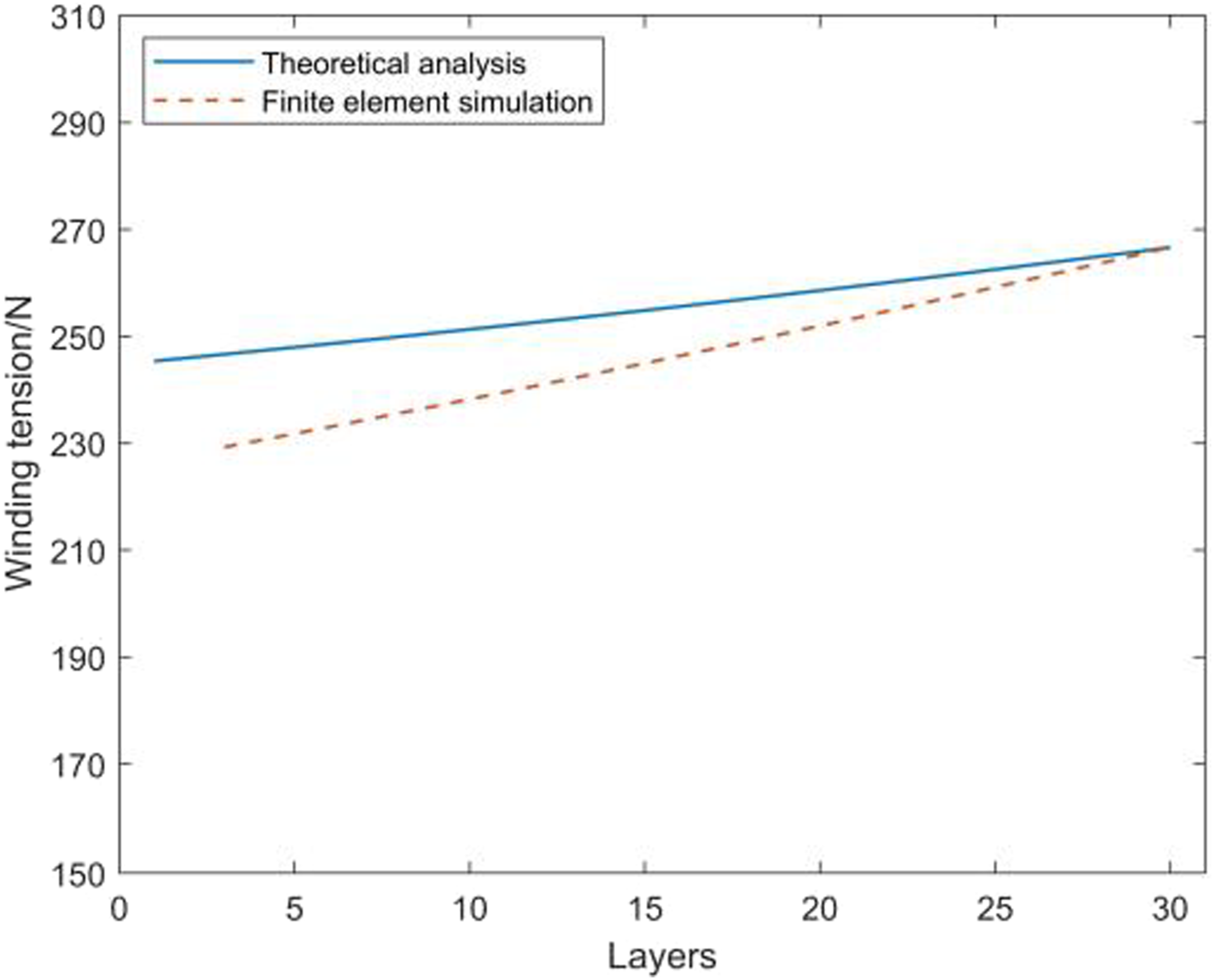
Figure 11 shows the radial compressive stress on the mandrel surface after winding, calculated by finite element simulation. The radial compressive stress on the mandrel surface after winding with constant tension is 14.86 MPa, while the theoretical calculated value is 14.87 MPa. The constant torque tension is 14.39 MPa, and the theoretically calculated value is 14.44 MPa. The radial compressive stress on the mandrel surface after winding with taper tension is 14.62 MPa, and the theoretically calculated value is 14.65 MPa. The equal stress winding has a compressive stress of 15.46 MPa, and the theoretically calculated value is 15.52 MPa. The simulation results are all close to the theoretical values. Therefore, the error is analyzed only for constant tension winding. Simulation results of radial compressive stress on the mandrel surface at the end of winding (a) constant tension; (b) constant torque tension; (c) taper tension(σ = 0.5); (d) Equal stress tension.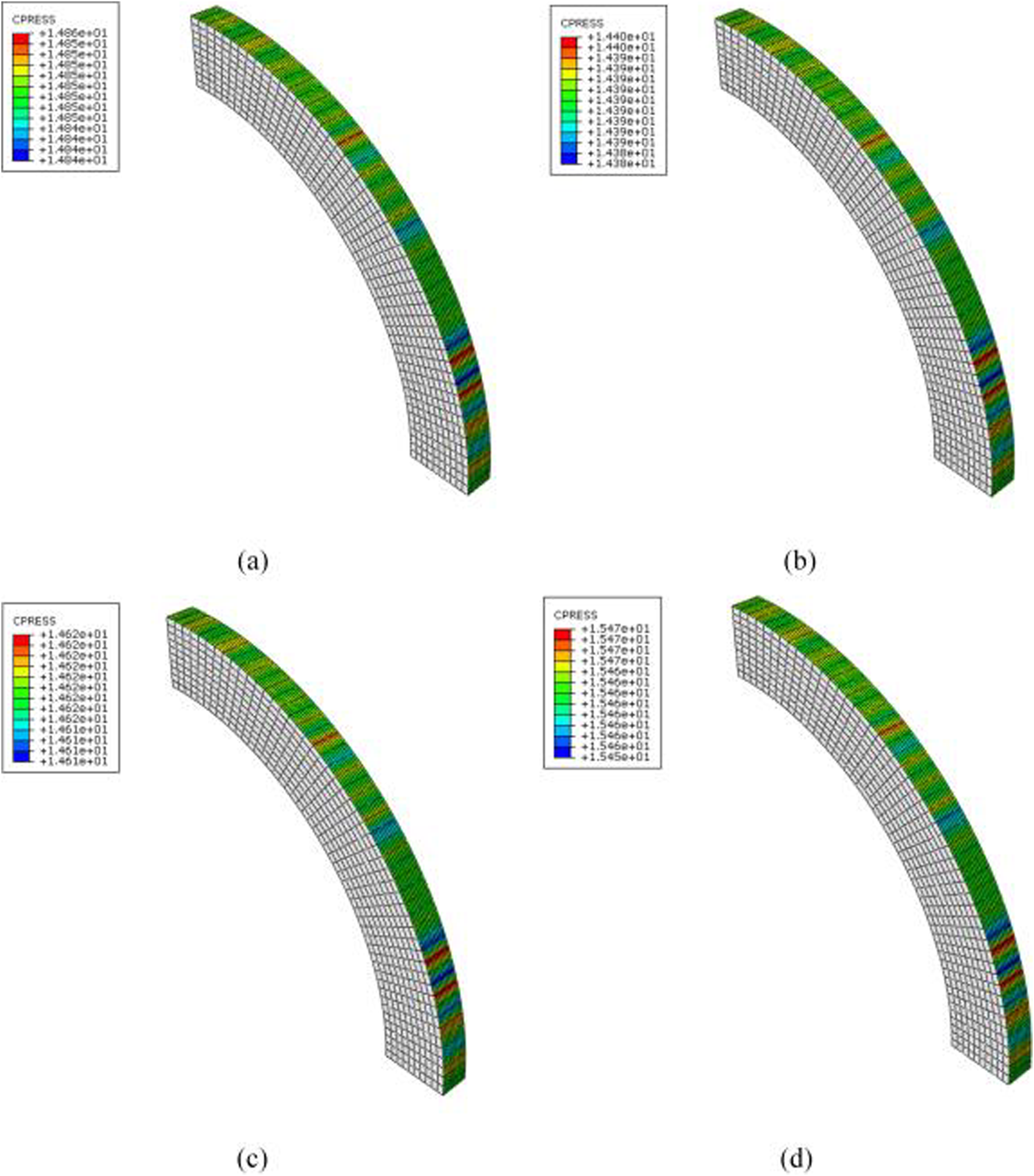
Figure 12 shows the variation of radial compressive stress on the mandrel surface throughout the constant tension winding process. Error of radial compressive stress on the mandrel surface during constant tension winding.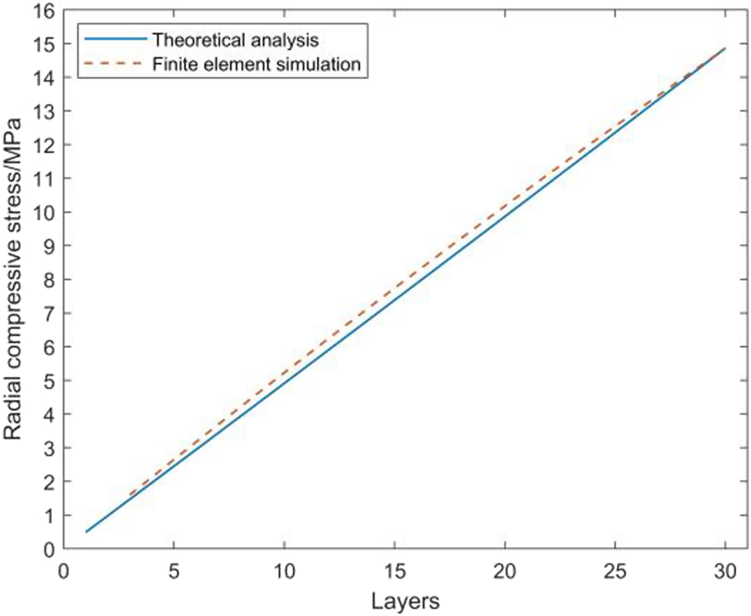
Notably, the finite element simulation results are in good agreement with the theoretical calculation results, and the maximum error occurs when winding to the 9th layer, revealing an error value of 0.4%. The above finite element simulation results and the theoretical calculation errors are within an acceptable range, verifying the reliability of the theoretical calculation in this paper.
Conclusion
In this paper, based on the thick-walled cylinder theory of elastic mechanics and the principle of small deformation, a mathematical model of the fiber stress distribution and radial compressive stress on the mandrel surface under the combined effects of tension and temperature field during the composite winding and molding process is established. The winding tension is designed and a tension application method is proposed to control the circumferential stresses in each layer of the composite material after the winding completion. The trends of circumferential and radial compressive stresses of composites under different initial tensions and stress presets are analyzed. As the winding process progresses, thermal stress delays the relaxation of the inner fibers under tensile forces. Under the three tension application methods of constant, constant torque, and taper tension, with the increase in the number of winding layers, the fiber circumferential stress decreases layer by layer from the inside to the outside, while the radial compressive force on the mandrel surface gradually increases. The constant stress tension can provide the largest radial compression force. When the stress per unit width of the fibers in each layer of the composite is 266.67 MPa, the radial compressive stress on the mandrel surface after 30 layers of winding is 15.52 MPa. In addition, a finite element simulation model of the composite winding molding process is established based on ABAQUS, and the results show that the maximum error of the circumferential stress is 6.7% from the theoretical calculation. The maximum error of radial compressive stress on the mandrel surface is 0.4%, verifying the reliability of the mathematical model in this paper. This result provides theoretical support for the tension design of the thermoplastic composite fiber high-tension winding molding process.
Footnotes
Declaration of conflicting interests
The author(s) declared no potential conflicts of interest with respect to the research, authorship, and/or publication of this article.
Funding
The author(s) disclosed receipt of the following financial support for the research, authorship, and/or publication of this article: This research is supported by the Fundamental Research Funds for the Central Universities (Grant No. 2232022D-21, Grant No. 2232024G-14), Opening Foundation of Shanghai Collaborative Innovation Center for High Performance Fiber Composites, Natural Science Foundation of Shanghai (Grant No.22ZR1401200, Grant No.23ZR1400500) and National Natural Science Foundation of China (Grant No. 51605296).