
Abstract
This paper presents a localised heating technique using an induction heater and a steel spring mandrel for post-forming of polyamide six carbon (CF/PA6) thermoplastic tubes. During heating, the mandrel is heated up more rapidly than the tube to catalyse tube heating to its formable temperature of 220°C. Upon heating, the tube matrix softens to enable fibre movements when a tube undergoes rotary draw bending (RDB), forming the desired curvature. Four sets of [±60°]₄ CF/PA6 tubes were formed using an induction heater incorporated RDB setup into 45°, 90°, 135°, and 180° bends with a bending ratio of 2. Optical characterisation and micro-computed tomography were performed to analyse tube fibre angle and geometry changes. Results suggest that the presented technique is capable of producing tube bends with significant improvements in efficiency and quality as compared to oven and infrared heating, opening up the potential for rapid post-forming of composite tubes for high performance applications.
Introduction
Carbon fibre reinforced polymer (CFRP) composite materials offer a desirable combination of high strength, high stiffness and light weight, making them increasingly popular for high-performance industries such as aerospace and automotive.1,2 The structural applications of CFRP composites can be further extended when they are applied in the form of tubular structures, which offer high flexural and torsional rigidities with respect to weight. 3 While straight tubes may be used in products such as bicycle frames, walking sticks, and pipelines, bent tubes may expand the range of applications into joints, frames, and even springs.4–6 Due to these advantages, a rapid and cost-effective production technique for customised CFRP composite tubular parts becomes essential to cater to the growing lightweight and high-performance demands.7,8
Production of tubular structures is possible for fibre reinforced composites with both thermosetting and thermoplastic matrices. On one hand, the production of tubular composite structures are generally limited to straight or continuous bends with large bending radii by techniques such as filament winding and pultrusion.9,10 On the other, discrete bends may be produced using thermoset composites via techniques such as hand layup. 11 As thermosetting matrices cannot be reheated to allow post-forming of thermoset composite parts, design-specific external moulds and internal tooling (often dissolvable) are usually required in the production processes using thermosets. 12 These processes, however, being complex, costly, and multi-step, are undesirable for industry scale rapid production.
Using thermoplastic pre-impregnated (prepreg) tapes, straight thermoplastic tubes can be rapidly produced via processes like braiding and laser based thermoplastic automated tape placement (TP-ATP).13–15 As the thermoplastic matrix system can be repeatedly heated to a soft and formable state, post-forming of straight thermoplastic tubes into desired curvatures, becomes possible.11,16 During the TP-ATP process, the matrix layer of a prepreg tape is locally melted by a laser beam to fuse the tapes layer-wise around a winding mandrel.17,18 The precise control of the number of plies and fibre angle per ply is possible based on application. 19 However, the geometry of tubes produced by TP-ATP is currently limited to straight or gentle curves. Due to tape tension during winding, possible interference of the placement heat with the mandrel, as well as complex coordinated motion requirements, tight or continuous bends cannot be wound directly. 20 Likewise, the geometrical limitations also apply to braiding. 21 Therefore, a more feasible process to produce curved tube geometry may utilise a bending technique to post-form straight thermoplastic tubes.
In previous studies, rotary draw bending (RDB) at elevated temperature was validated as a quick and cost-effective technique to post-form straight thermoplastic tubes produced by braiding and TP-ATP into desired curvatures.20,22,23 Using RDB, a straight thermoplastic tube is first heated to its matrix melting temperature, then formed by turning the bending die into a desired bending angle in the process known as post-forming. 20 Tensile stress is applied to tube extrados and compressive stress is applied to tube intrados during forming by the bender dies. 22 At elevated temperatures, the matrix of the straight tube softens to allow fibre relocation and reorientation when these stresses are induced. 22 The fibre movements result in differences in strains experienced by tube intrados and extrados, forming curvatures. 24
Tooling cost is reduced as customised bending angles of the same bending ratio can be achieved without changing the bender dies using RDB, while continuous bends may also be possible to enhance degrees of freedom in tubular structure design.22,25 Hence, RDB offers great advantages which helps to address the complexity and high cost of curved thermoset tubular structure production as well as the geometrical restrictions of conventional thermoplastic tubular structure production, 24 making it desirable for rapid production of curved composite tubular structures with the possibility of design customisation.
Before bending, a straight thermoplastic tube can either be heated in an oven to allow post-forming under isothermal conditions or locally within its bending zone. 26 Li et al. demonstrated that forming under isothermal conditions using oven heating is capable of producing high quality bends as the whole tube is heated up uniformly. 22 However, this process was found to be inefficient, taking about 5 h due to the need to place the complete bender assembly containing the straight tube into the oven for heating. Additionally, a flexible silicone mandrel was used to provide internal support to the tube during forming under isothermal conditions, which allowed fibre movements throughout the heated tube. When tensile stress was applied by the bender dies to the tube during forming, tube extrados experienced slight inward displacement towards the tube neutral axis when insufficiently supported by the soft silicone mandrel. As a result, geometrical distortions, namely reduced tube bending zone diameter and extended tube extrados beyond its bending zone were observed. 22 Alternatively, Engel and Böcking used four short wave infrared (IR) emitters placed at 90° intervals around the tube circumference to perform localised heating of tube bending zones. 20 The localised heating process was significantly quicker than oven heating, with an average heating time of 200 s per tube. 20 An uneven temperature profile, however, was observed on the tube surface with a maximum temperature gradient of 50°C between areas directly exposed to the IR emitters and the rest of the tube section. 20
In order to enable rapid post-forming of thermoplastic tubes for industrial manufacturing and applications, a novel heating technique needs to be developed to address both inefficiency and geometrical distortion of oven heating and the uneven tube temperature profile of localised heating by IR heaters. This study presents a localised heating technique using an induction heater for RDB of carbon fibre reinforced polyamide six thermoplastic (CF/PA6) tubes made in a TP-ATP process. The presented localised induction heating technique is more efficient than the conventional oven heating technique to enable more rapid forming which is a vital prerequisite to industrial application. Four sets of [±60°]₄ CF/PA6 tubes will be formed to bend angles 45°, 90°, 135° and 180°, respectively, using an induction heater incorporated RDB setup. A long wave infrared (LWIR) camera will be used to record tube surface temperature profiles during forming. Optical measurements using a Micro-Vu Vertex automated precision measurement system will be conducted to measure the fibre angles of tube bending zones both before and after post-forming. The measured fibre angles will be evaluated against the formerly derived fibre angle prediction model and the evaluation results will be compared with those from the previous study on forming under isothermal conditions. 22 Micro-computed tomography (µCT) images will also be acquired on one test tube of each bending angle (i.e. four tubes in total) to evaluate geometrical changes.
Methodology
CF/PA6 tube manufacture
This study used straight [±60°]₄ CF/PA6 tubes manufactured using a TP-ATP system (AFPT GmbH).27,28 The [±60°]₄ laminate configuration was chosen as the initial fibre angles of the tube layers allowed tube forming via fibre relocation and reorientation following. 24 This was also consistent with the tubes used in the previous study on post-forming under isothermal conditions to allow direct comparison of results from the two post-forming techniques.
The process used 12 mm wide and 0.13 mm thick Celstran® CFR-TP PA6 CF60-01 tapes with a fibre volume content of 48%. The tapes were wound onto a 20 mm diameter solid chromed steel mandrel which was initially at room temperature. A process temperature of 280°C, controlled by regulating the laser power, was used for manufacture and a placement rate of 12 m/min with a consolidation force of 200 N following a conventional helical filament winding pattern. Three circuits (p = 3) and a shift parameter of one (Nˢ = 1) per ±60° layer pair, as defined in, 29 were used to manufacture the straight CF/PA6 tubes. This led to the manufactured tubes with a winding angle of approximately ±53° for their innermost plies, increasing gradually to ±57° for their outer-most ply. The manufactured tubes had a total of eight plies each, and were measured to have an average inner diameter (di) of 20 mm and outer diameter (do) of 22.6 mm, resulting in an average wall thickness of 1.3 mm per tube.
The total length of each tube consisted of its initial bending zone length, a 40 mm clamping length and a 20 mm hanging length on the two ends of the bending zone (Figure 1(c)). The initial bending zone length, l0, of a tube can be determined by multiplying the bending diameter, 2rb, with the ratio between tube bending angle, α, and 360°. CF/PA6 tube parameters: (a) evenly spaced fibre angle measurement points on the intrados and extrados of the tube bending zone before forming, (b) bending parameters, (c) circumferential parameters.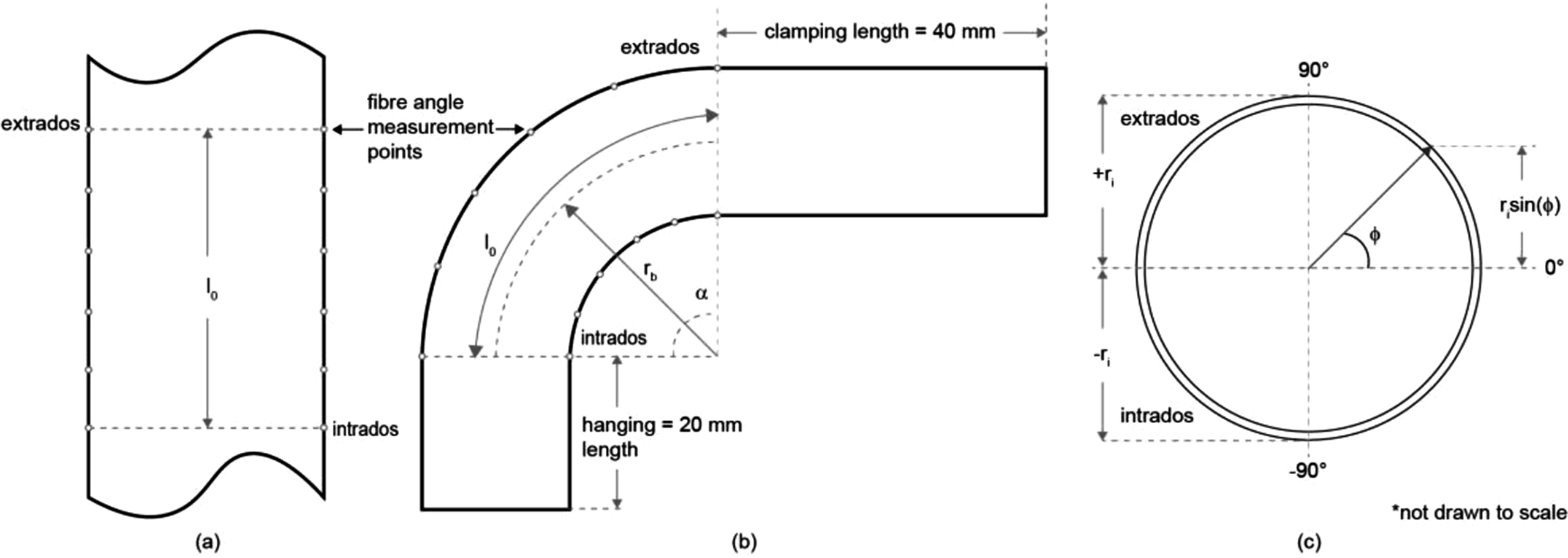
Post-forming experiments
Rotary draw bender set-up
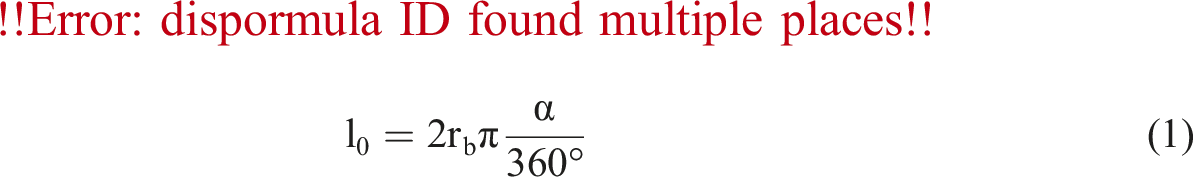
RDB post-forming experiments were conducted using a setup containing a bespoke rotary draw bender made of aluminium dies and an Across International IH8A induction heater. The rotary draw bender consists of the same key elements akin to a traditional metal tubing bender except for the wiper die, which is redundant in this case due to the direction of the force application. A cut-out was made on the main bending die to accommodate the induction coil, as shown in Figure 2. The dies of the bender used in this study could be replaced by dies of other dimensions for other applications. In this study, a straight CF/PA6 tube was bent by manually turning the main bending die. The bending process may be automated by attaching a motor to the main bending die for future investigations and industrial applications. CF/PA6 tube RDB operation: (a) mandrel heating, (b) tube bending, (c) photo of the post-forming setup.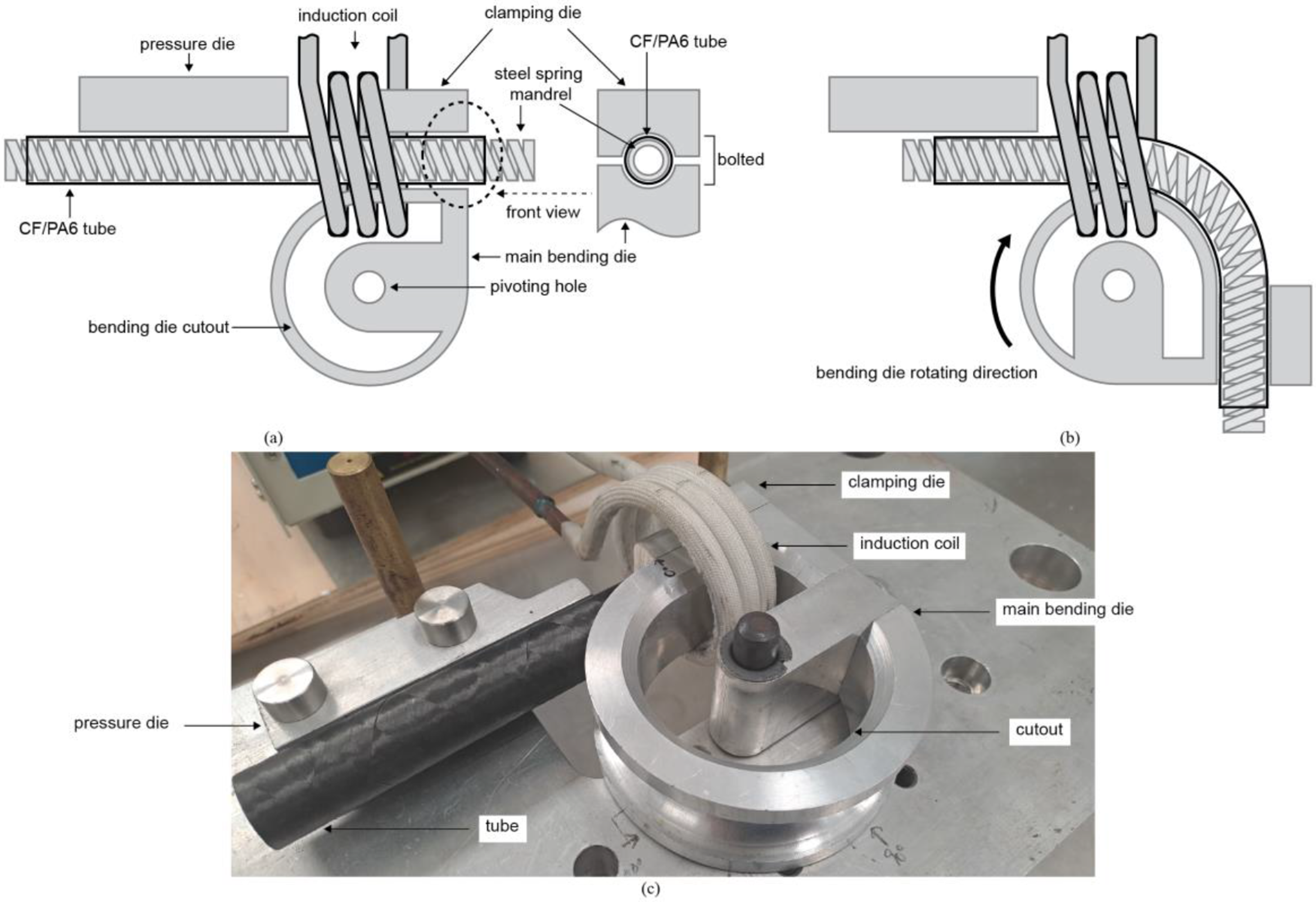
The induction heater has a maximum output power of 8 kW and output frequencies between 30 and 80 kHz. The output current for this study was set to the minimum of 105 A following 26 to minimise undesired heating of other aluminium bender parts. The heater used a three-turn copper induction coil with a total length span of 25 mm, an internal diameter of 55 mm and an external diameter of 67 mm to enable induction heating of the work piece within the coil. The coil was concentric to the straight CF/PA6 tube, and its centre was aligned with the start of the bending zone, as shown in Figure 2(a).
A steel Clipsal 266MD25 medium duty conduit bending spring was used as the bending mandrel for the post-forming process. The steel mandrel was chosen as being (1) made of a rigid material in a bendable design, and (2) ferromagnetic and highly responsive to induction heating.30,31 Previous study also showed that the spring mandrel can provide more consistent internal support during post-forming of CF/PA6 tubes and can be easily removed from the post-formed tubes. 32 The mandrel had an average coil diameter of 19.5 mm when both straight and bent, to provide consistent and rigid internal support to the tube during forming. The diameter of the mandrel was 0.5 mm smaller than the inner diameter of the straight tube to allow easy loading into and unloading out from the tube. As the mandrel was heated up at a faster rate than the tube in the induction coil, a shorter tube heating time became possible by the joint effect of heat transfer from the heated mandrel and induction heating of the tube itself. 26
Forming parameters
In this study, four sets of three identical [±60°]₄ CF/PA6 tubes were post-formed to bending angles of 45°, 90°, 135° and 180°, respectively, in the rotary draw bender with a bending radius of 46 mm. This led to a bending ratio of two following the previous study 22 on post-forming under isothermal conditions.
The CF/PA6 tubes have a formable temperature of 220°C, where their matrix is partially melted to allow fibre relocation and reorientation when a bending load is applied to form curvatures.22,24 Post-forming was initiated by rotating the bending die when the tube surface temperature stabilised at 220°C in the forming experiments. As only one type of tape was used to manufacture the tubes used in this study, viscosity was kept as a constant and crystallinity effects were neglected.
Post-forming method and experimental procedure
The RDB post-forming process of CF/PA6 tubes consists of two main steps, namely heating and bending, as shown in Figure 3. Induction heating process: (a) initial mandrel position, (b) heat cycle mandrel position.
For the heating process, the mandrel was divided into multiple sections of identical length corresponding to the span of the induction coil, represented by sections A and B in Figure 3. Before heating, the mandrel was inserted into the tube and positioned to have its section A, 30 mm from its end, within the coil, as shown in Figure 3(a). A preheating process of the mandrel was implemented to ensure relatively even temperature distribution along the tube bending zone for a continuous bending process to produce consistent and smooth tube bends. A quicker bending rate was also possible with the preheated mandrel. In this process, mandrel section A was first heated until tube surface temperature within the coil stabilised at approximately 180°C. This process took an average of 40 s across the experiments. Section A was then heated until the tube surface temperature stabilised at 200°C, which took an average of 20 s. Stepped heating was used to allow better tube temperature control and prevent overheating of the tube. After which, while the tube was fixed in place by the bender dies, the mandrel was moved to have its section B positioned within the coil, as shown in Figure 3(b), where the tube surface temperature would drop to approximately 160°C. Section B was heated until tube surface temperature stabilised first at around 180°C, then at around 200°C, corresponding to the average heating times of 30 s and 20 s, respectively.
In this study, each preheat mandrel section corresponded to approximately 22.5° of tube bending angle (i.e. four preheat mandrel sections for a tube with 90° bend) and the preheating process was repeated for all mandrel sections necessary for a designed bending angle. For the final preheat section, the mandrel was further heated for the tube surface temperature to increase and stabilise at 220°C to allow forming. The average heating time of this step was 10 s.
Once all mandrel sections were preheated and the tube surface temperature stabilised at its formable temperature, the bending die was rotated to the desired bending angle, as shown in Figure 2(b). The bending die was turned at a uniform bending rate of approximately 15°/s. Meanwhile, the induction heater was turned on for 2 s at 1 s intervals to keep the tube at its formable temperature of 220°C. Finally, the post-formed tube was held in position during re-solidification of the matrix until the tube bending zone surface temperature dropped below 100°C to minimise the effect of spring-back following. 20 To remove to mandrel from the post-formed tubes, the spring mandrel was twisted out from the tubes. Unlike the removal of silicone mandrel studies in previous experiments, 32 sticking of the spring mandrel to tube walls was not observed.
Forming behaviour characterisation
Fibre angles
Using a Micro-Vu Vertex automated precision measurement system, tube bending zone fibre angles were measured both before and after forming at evenly spaced points as shown in Figures 1(a) and 1(b), following. 22 The Micro-Vu system is a type of coordinate measuring machine that uses optical sensors to accurately measure an object. A pattern of light is projected onto the object being measured by the system to capture the image of the deformed object pattern. The Micro-Vu system uses advanced software algorithms to process and analyse the captured image, enabling precision measurements including that of CF/PA6 tube surface fibre angles in the bending zone.
Fibre angle measurements were taken at points of even intervals along tube intrados and extrados, where the most significant fibre angle changes would occur. 22 The fibre angles measured before forming were processed using the previously validated post-forming fibre angle prediction model (equations (2) and (3)) from 22 to obtain predictions of their corresponding post-formed fibre angles. These predictions were compared with the fibre angles measured after forming to identify potential discrepancies.
The ultimate (maximum and minimum) post-formed fibre angles were calculated using tube bending radius (rb), initial fibre angle (θ0), ply radius (ri), and angular position of the point of interest (Φ) at the middle of the bend (Figure 1):
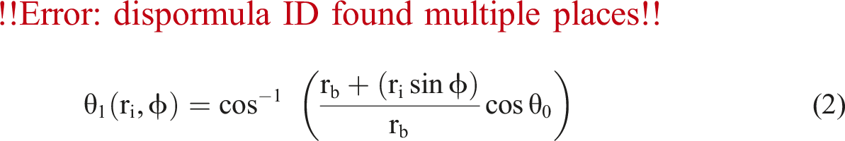
For tubes formed to bending angles (α) between 0 and 90°, their post-formed fibre angles at any point of interest along the bend were predicted by:
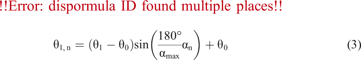
For tubes formed to 90° < α ≤ 180°, there was a constant fibre angle region at 45° from the bending zone boundaries. The constant fibre angle region in a bent tube was where its post-formed fibre angles at any point along the intrados and the extrados within the region corresponded to θ1. 22
Tube geometries
Tube geometries were characterised in terms of tube diameter and tube axial strains (ε) obtained from the visualisations of the µCT 3D images as shown in Figure 5(b). ε was computed using l0 obtained from equation (1) and tube axial length after forming (l
1
):

Using equation (4), The actual ε of a tube was computed using l1,m measured from µCT images of the tubes. The theoretical ε at tube extrados and intrados was calculated using the theoretical axial length of a tube, l1,t formulated using α and tube radius, r:

The centre of a bend was where the most significant deformation would occur, as discussed in.22,24 Hence, tube bending zone diameters were measured at the centre of each bend corresponding to the tube angular position of α/2 following. 22
After forming, the four CF/PA6 tubes were imaged using a HeliScan™ µCT instrument hosted at the Australian National University (ANU) CTLab for the analysis of tube geometries and void content. The instrument is equipped with a 60 kV X-ray micro-focus source as well as a 3040 × 3040 pixels flat panel detector. Prior to imaging, the four samples were placed and firmly secured inside a 100 mm diameter aluminium tubular cantainer to prevent sample movement during scanning. The container was then placed on a rotating motor-controlled stage, where a total of 8200 2D radioscope projections were acquired. Greyscale volumetric images of the complete 3D tubes geometry were generated from the acquired 2D projections using a proprietary ANU reconstruction algorithm. 33 One scan was conducted for each bending angle. The total acquisition time was 17 h and the scanning resolution (i.e. voxel size) of the reconstructed images was 47.1 µm. This resolution allows for accurate geometrical analysis and large defect characterisation, although it is insufficient for analysis of smaller voids and to measure the orientation of the ∼7 µm diameter carbon fibres.
Image Processing and Visualisation
Image processing and visualisation were done in Dragonfly ORS to first separate and digitally extract the tomongram of each tube, and then mask and spatially align the four individual tomograms for dimensional measurement. Void segmentation was performed on tube bending zones using the greyscale thresholding method, where a threshold value is chosen based on the CT image greyscale histogram to separate the voids from the other components.
34
The same approcach was followed to segment the walls of the tubes (matrix and fibres undistinguished) with an additional step added to close and fill all internal holes. The void volume fraction for the bending zone region is then calculated as the ratio between segmented voids and segmented tube walls. The initial voids straight CF/PA6 tubes before post-forming were relatively low (∼0.5%). The void segmentation of a CT scan of an example tube from the same batch (same material and winding angles) was shown in Figure 4. Void segmentation of a straight CF/PA6 tube before forming.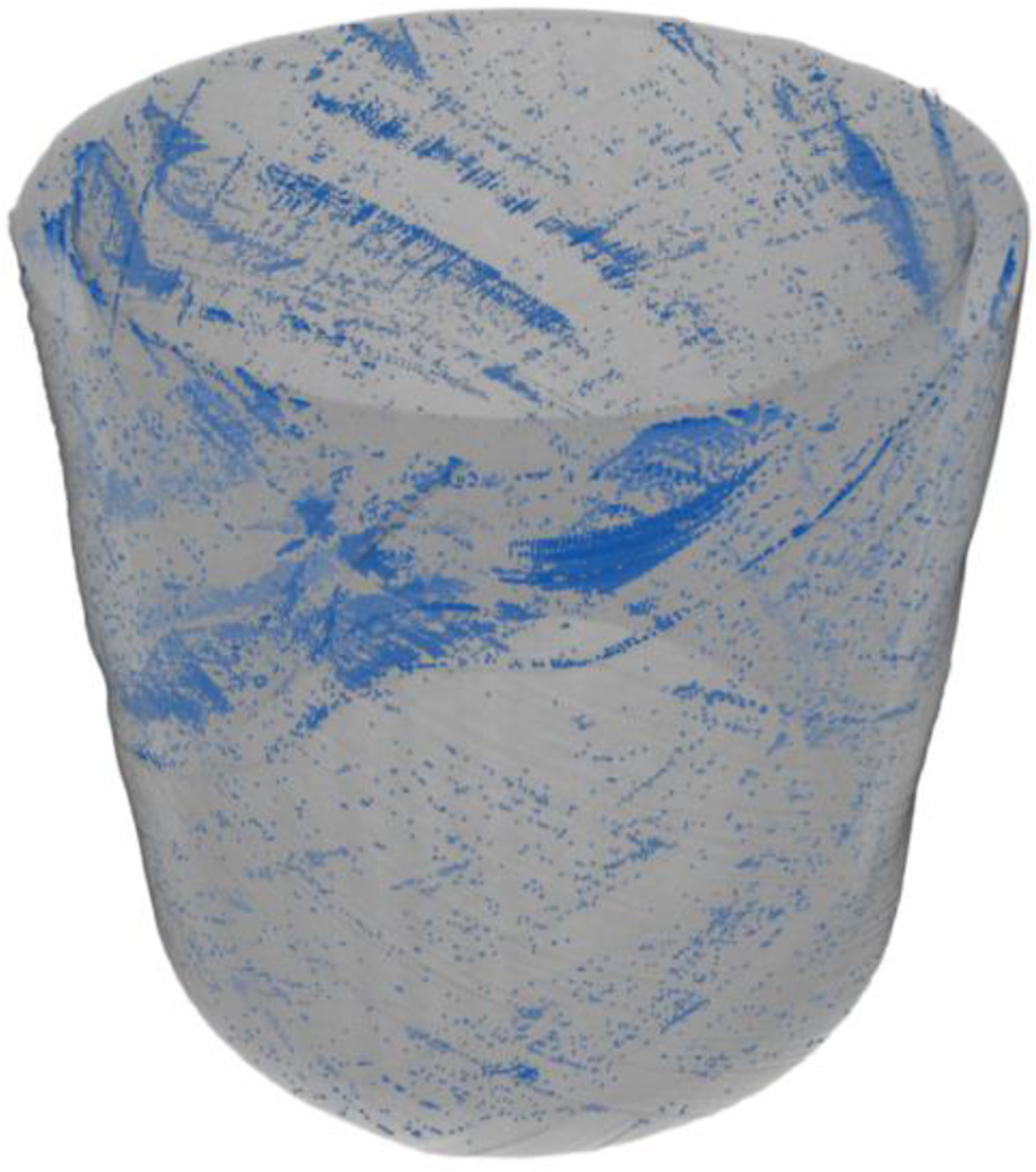
Tube Temperature
A Xenics Gobi-640-Gige LWIR camera placed 400 mm from the measurement point, as shown in Figure 5, was used to monitor the outer surface temperature of the tube area within the coil throughout the post-forming process. The CF/PA6 tubes have an average emissivity of 0.87, as determined in
26
for the calibration of LWIR camera temperature measurements. Temperature measurement setup.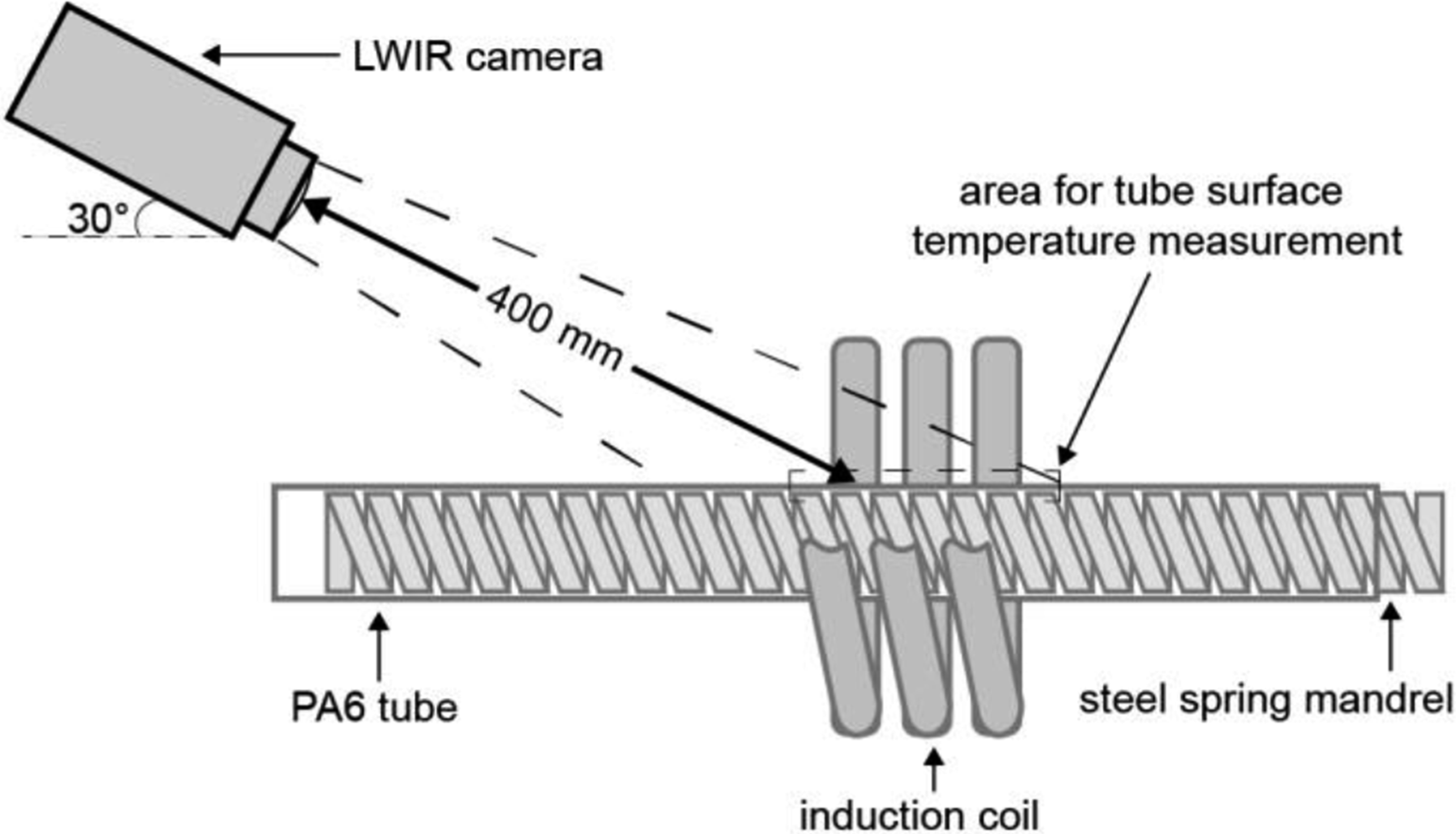
Results and discussion
The average induction heating times of tubes formed to 45°, 90°, 135°, and 180° were 120 s, 220 s, 220 s, and 420 s, respectively, which were significantly reduced from the average heating time of 5 h by oven heating.
22
From the tubes post-formed via localised heating, neither wrinkles nor delamination were observed on tube surfaces, which appeared smooth, as shown in Figure 6. The geometrical changes of tubes formed via localised induction heating were evaluated and compared with those formed under isothermal conditions
22
to determine if tube geometrical distortions have been reduced. Similarly, post-formed fibre angles, both measured and predicted, of tubes formed via induction heating were compared to those of tubes formed under isothermal conditions,
22
as fibre angle changes were affected by tube geometrical distortions. Example of (a) a straight CF/PA6 tube before forming, (b) a CF/PA6 tube formed via localised heating to 90°, (c) a CF/PA6 tube formed under isothermal conditions to 90°.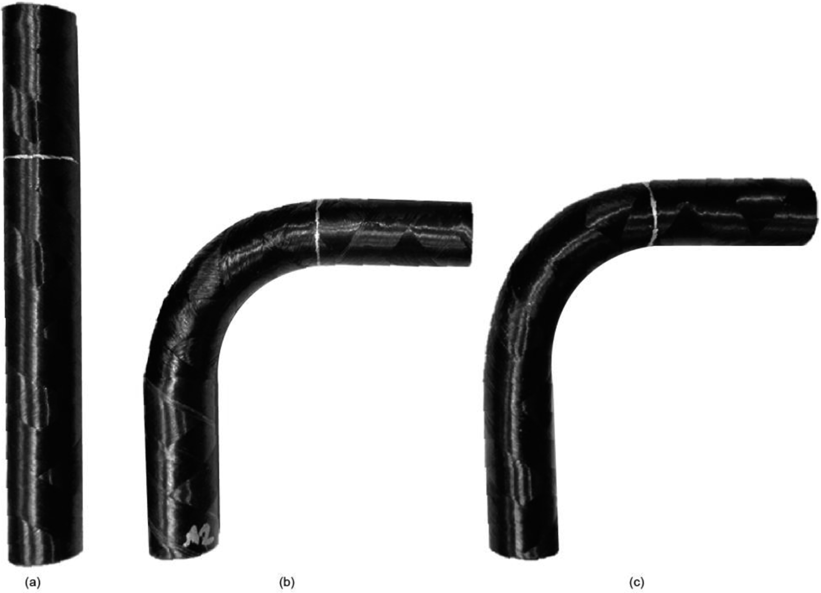
Tube geometries
From the μCT analysis, tubes post-formed both by localised heating and under isothermal conditions were found to have higher void contents than straight tubes (∼0.50%) before forming. Between the post-formed tubes, the induction heated tubes were measured to have higher void contents (∼4.99%) than the oven heated tubes (∼1.15%). Voids in the induction heated tubes were mainly distributed within their bending zones (Figure 7(a)), suggesting the potential contribution of the technique to the increasing void contents, which will be subjected to future investigations. Additionally, large void morphology tended towards flat patches in the interlaminar regions particularly on the tube extrados. The greater occurrence of voids on the extrados was likely due to differences in compression of the tube wall. For which, the tube extrados was only supported on the inside by the spring mandrel while the intrados was supported both on the inside by the mandrel and on the outside by the main bending die. (a) μCT tomogram of a tube formed to 90° bend angle with voids highlighted in blue, (b) sectioned tube view for dimension measurements.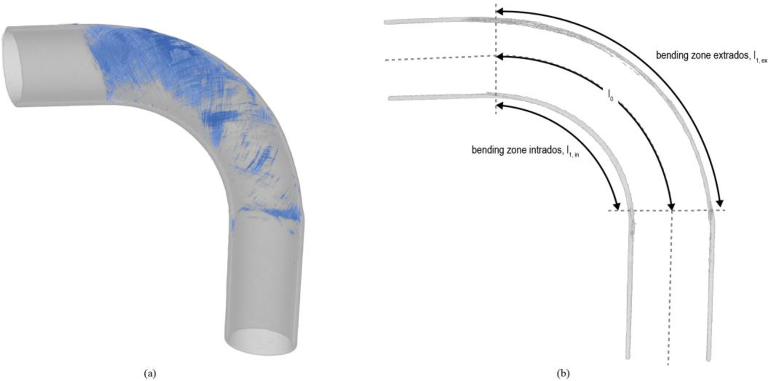
As a result of localised heating, fibre movements in the semi-molten matrix during forming were contained within tube bending zones. Additionally, the steel spring mandrel provided more consistent and rigid internal support to the tube than the previously used silicone mandrel. Their combined effect reduced both tube extrados extension beyond the bending zone and displacement towards the tube neutral axis due to the tensile stress applied during forming. Consequentially, tube mechanical properties may be more consistent (and predictable) as tube ovality was better maintained by post-forming via localised heating.
Tube dimensions were measured from the sectioned views of their μCT images as shown in Figures 7(b) and 8 and were summarised in Tables 5 and 6 in Appendix A. Tube extrados lengths measured after forming were normalised to their theoretical lengths for tubes bent to all four bending angles in Figure 9(a). Tube bending zone diameters measured after forming were normalised to their original do of 22.6 mm before forming in Figure 9(b). positions of the sections taken from the μCT tomogtam for tube geometry measurements. Comparison of tube geometries between those formed via localised heating and under isothermal conditions
22
: (a) Comparison of tube extrados, (b) comparison of tube diameter.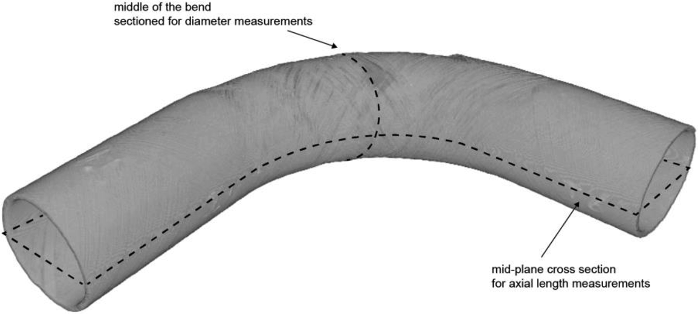
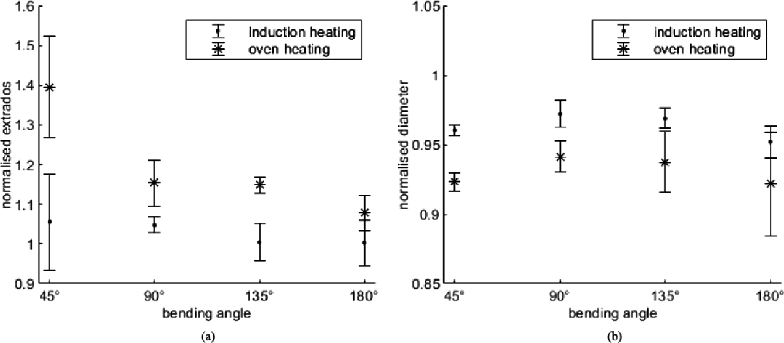
Comparing the extrados extensions of tubes formed using localised heating and tubes formed under isothermal conditions, 22 the average extensions experienced by the former were 5.60%, 4.74%, 0.41%, and 0.31%, which were 85.79%, 69.08%, 97.19%, and 96.15% less than the latter for tubes formed to 45°, 90°, 135° and 180°, respectively, reflecting significant reductions in unwanted extrados extensions. Similarly, tubes formed using localised heating experienced smaller tube diameter reductions compared to those formed under isothermal conditions. The average diameter reduction measured for tubes formed to 45°, 90°, 135° and 180° using localised heating was 3.95%, 2.77%, 3.11%, and 4.81%, respectively, which are 48.56%, 52.76%, 50.12%, and 38.49% less than those formed under isothermal conditions. 22
The lower geometrical distortions found in tubes formed via localised heating than those formed under isothermal conditions was likely due to their different heating regions and mandrels. When tubes were formed under isothermal conditions, fibre movements were possible beyond tube bending zone as the entire tube was heated. Additionally, a soft silicone mandrel was used during forming under isothermal conditions. During which, extrados of the tubes pressed into the soft silicone mandrel due to the bending load, causing undesired flattening of tube extrados which extended from the bending zone to the rest of the heated tube sections. On the other hand, only tube bending zones were softened during forming via localised heating to restrain fibre movements and the steel spring mandrel was able to better resist inward extrados travel during forming. Hence, forming via localised heating using the steel mandrel was capable of better maintaining tube geometry than forming under isothermal conditions using the silicone mandrel.
It is worth noting that a small amount of extrados extensions were still found on tubes formed via induction heating despite localised melting of their bending zone matrix. During forming, neighbouring sections of the bending zone boundaries were also heated via heat transfer from the heated tube bending zones. Softening of the neighbouring matrices enabled a small number of fibre movements beyond tube bending zones to initiate fibre relocation and reorientation within tube bending zones during forming, which avoided fibre buckling due to sudden fibre angle change at bending zone boundaries. Additionally, the 0.5 mm clearance between the spring mandrel and the tube inner ply allowed room for extrados displacement towards the tube neutral axis during forming. Their combined effect was likely to cause the extrados extensions found on tubes formed via induction heating.
Fibre angle
Measured post-formed fibre angles showed close agreement with the predictions from equations (2) and (3), with most predictions being within the standard deviations of the measurements. The standard deviation was derived from multiple tube measurements and indicated the variability of the results. A closer agreement between measurements and predictions was observed from tubes formed via localised induction heating than for tubes formed under isothermal conditions (via oven heating), as shown in Figures 10–13. In these figures, both the measured and the predicted fibre angles were normalised to their corresponding initial fibre angles measured from the tubes (Appendix A), and the standard deviations were calculated from the results of all samples of the same measurement points.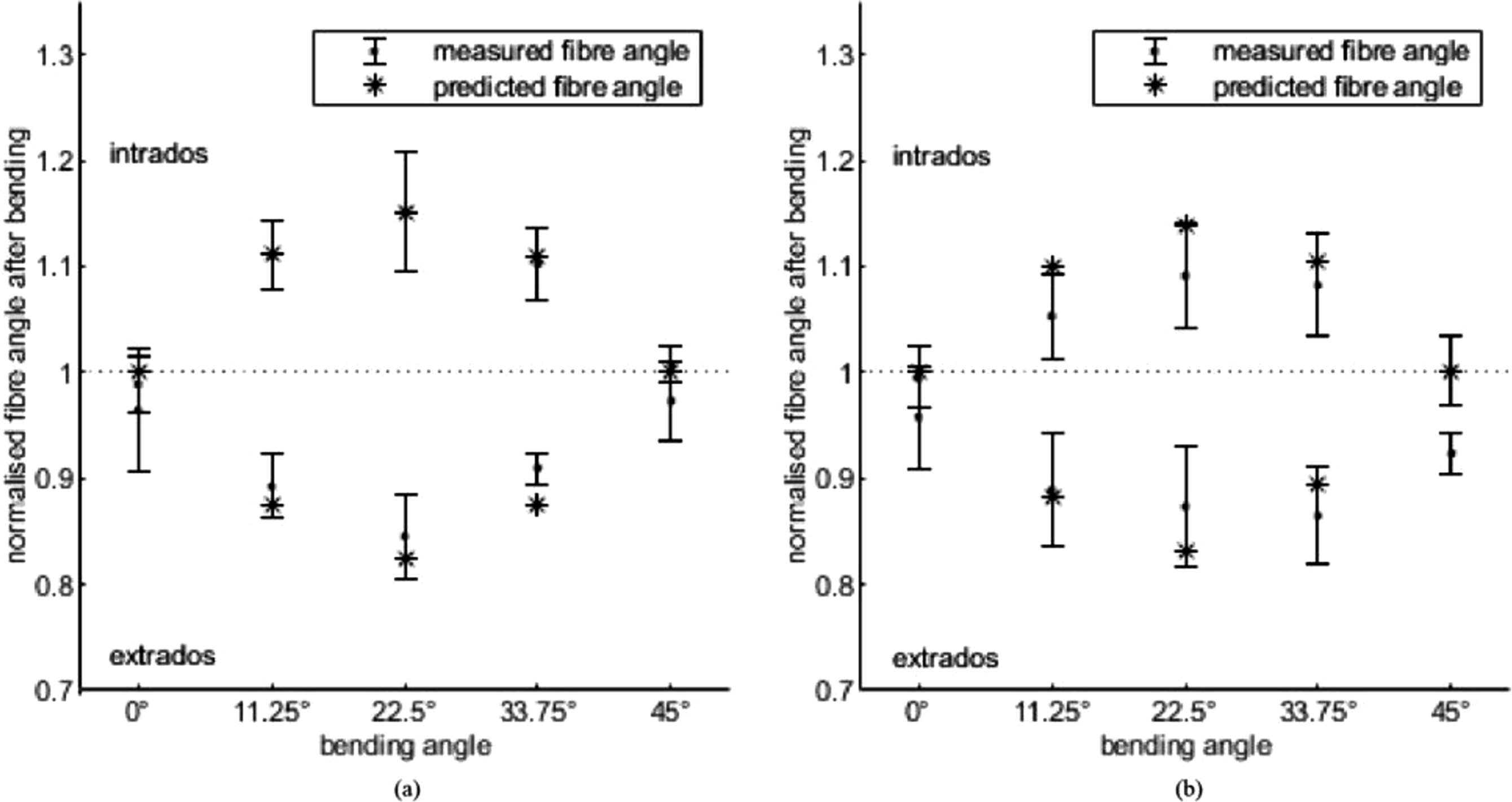
For tubes formed to 45°, improvements on the agreements between the measurements and the predictions are found at tube intrados of the induction heated tubes (Figure 10(a)) as compared to the oven heated tubes (Figure 10(b)). While the intrados predictions of both induction and oven heated tubes fell within the standard deviations of their measurements, the predictions of the former showed greater correspondence to the mean values of the measurements. On the other hand, slight deviations of the tube extrados predictions from the mean values of the measurements found in the induction heated tubes revealed potential geometrical distortions similar to those of the oven heated tubes.
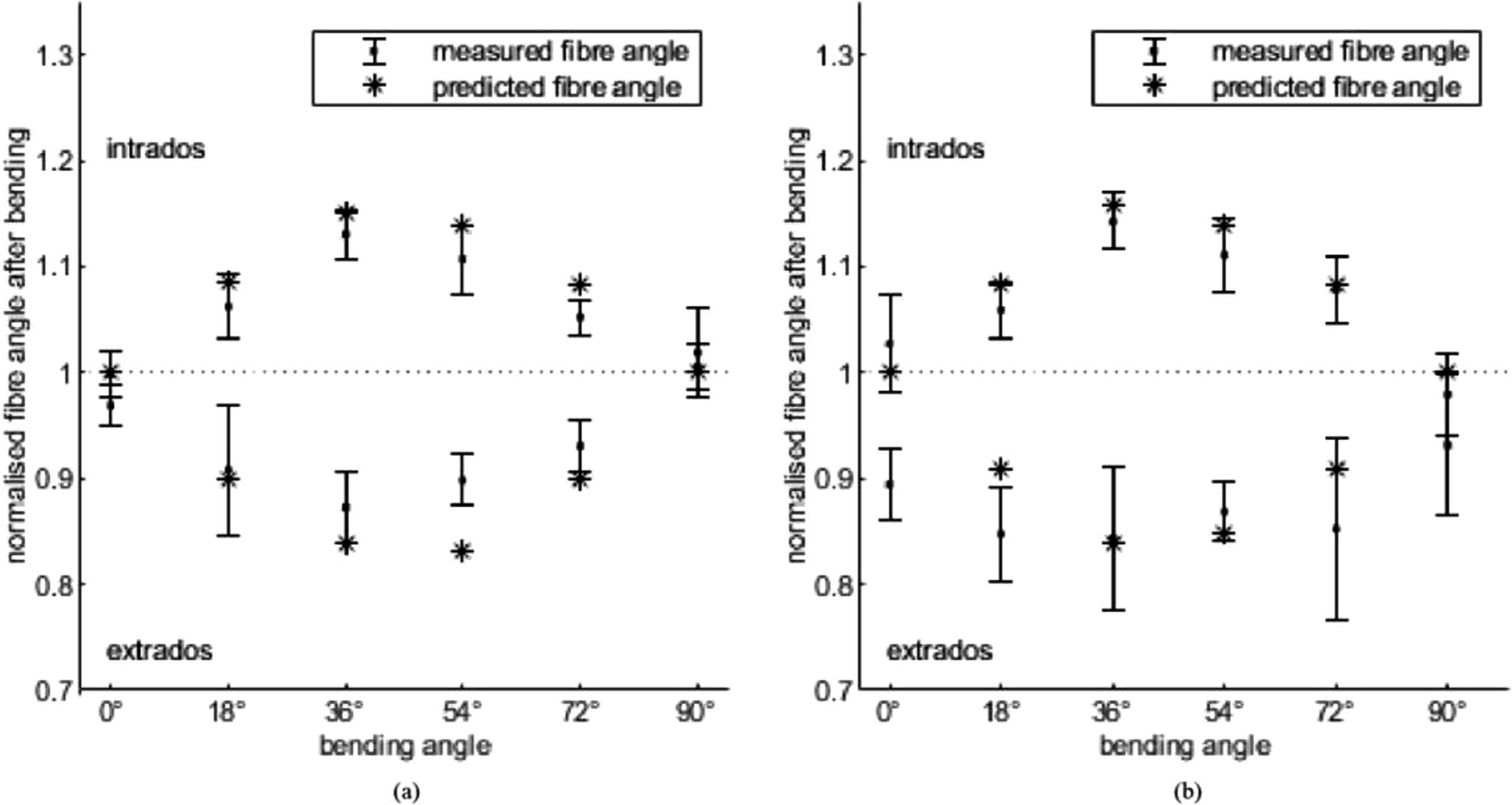
Comparison of the predictions and measurements for induction heated tubes formed to the bending angle of 90° showed good agreements in general (Figure 11(a)). However, no obvious improvements were observed as compared to tubes formed via oven heating (Figure 11(b)).
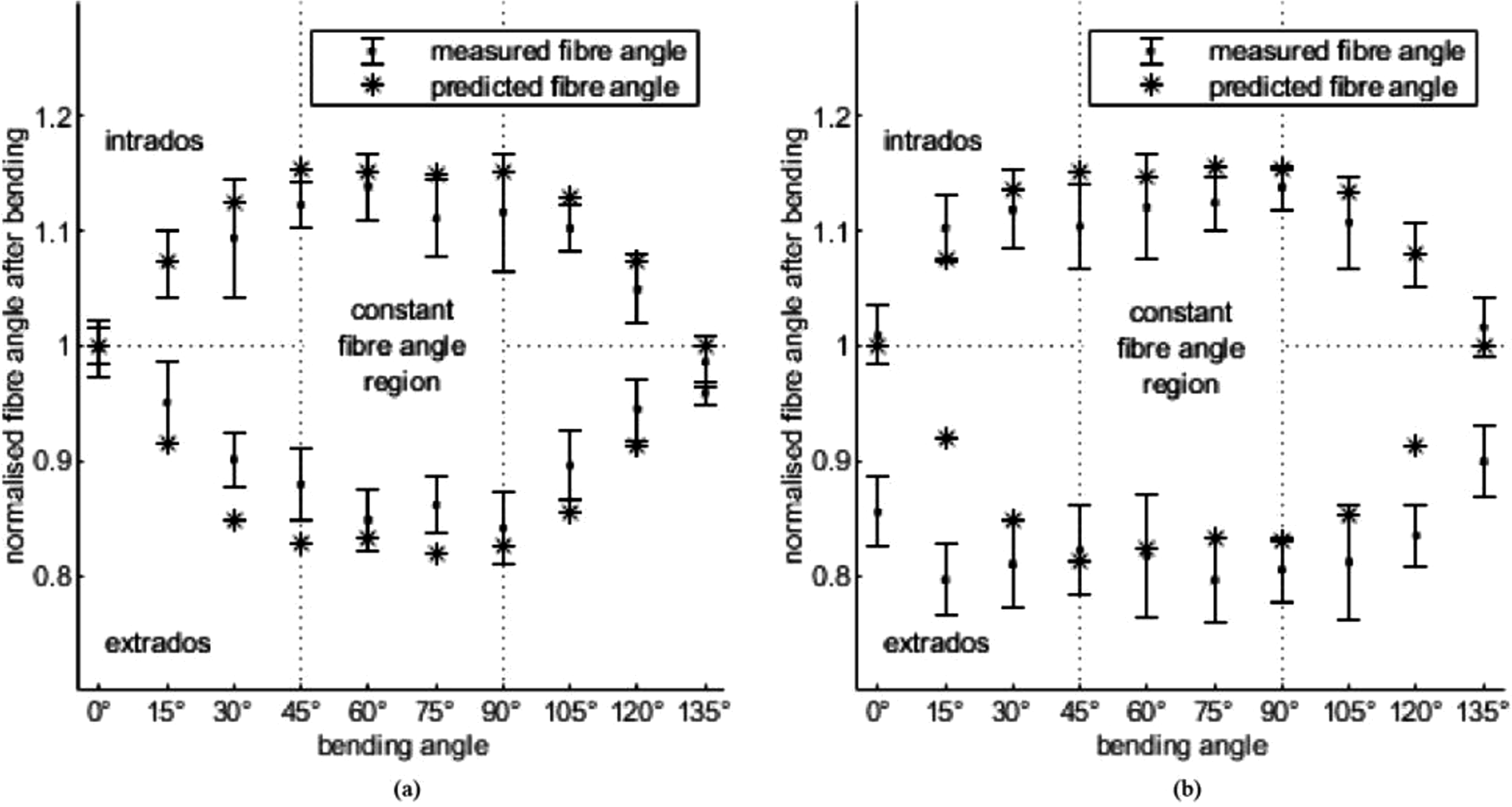
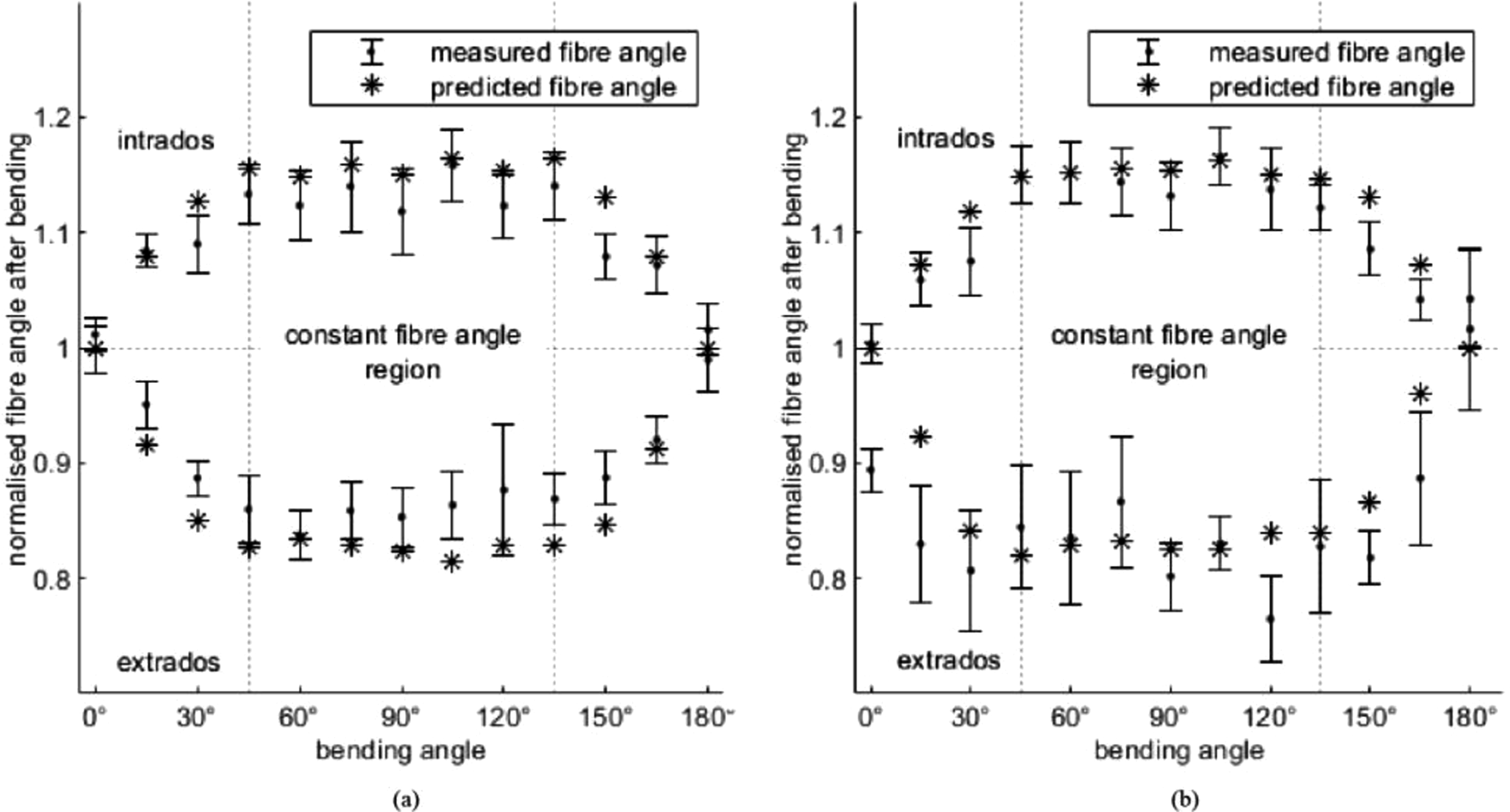
For tubes formed to 135° (Figure 12) and 180° (Figure 13), good agreements between the post-formed fibre angle predictions and measurements were found on the intrados of the induction heated tubes similar to the oven heated ones. As compared to the oven heated tubes, closer agreements between the predictions and the measurements were found on the induction heated tubes (Figure 12(a) and 13(a)) at points between the constant fibre angle regions and the boundaries of the extrados. These closer agreements were likely due to better maintenance of tube geometrical integrity by the proposed technique during forming as discussed in Tube Geometries.
The fibre angle prediction model assumed the tube to maintain a uniform circular cross-section with constant circumference during forming.
22
As the tubes formed via induction heating experienced smaller extrados distortions, their geometry was closer to the assumptions by the model, hence showing closer agreement between measured and predicted fibre angles than tubes formed under isothermal conditions. Thus, the presented localised heating technique was validated to be capable of reducing tube geometrical distortions and enhancing consistency in terms of fibre angle changes during forming (Figure 14). Comparison between corrected predictions and measured post-formed extrados fibre angles for tubes formed to (a) 45°, (b) 90°, (c) 135°, and (d) 180°.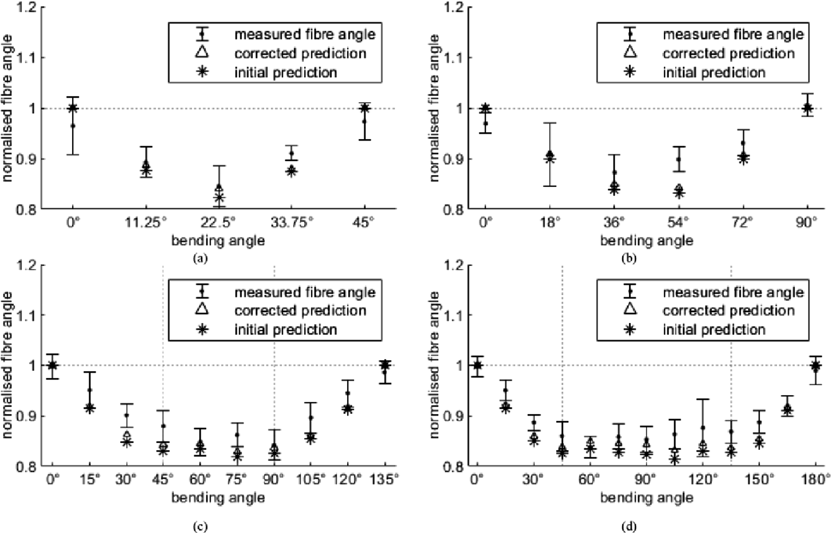
While fibre angles measured at the start and the end of tube bending zones showed close agreement with the predictions for tubes formed using localised heating, minor discrepancies were observed on extrados fibre angles within tube bending zones. The measured fibre angles at tube extrados exhibited smaller changes upon forming than predicted for tubes formed to all four bending angles. During forming, tube intrados was supported by the main bending die as well as the mandrel pressed onto it due to the direction of the bending load, leaving no gap between the mandrel and tube intrados. This, however, formed a gap between tube extrados and the mandrel due to the initial 0.5 mm clearance between the tube and the mandrel. This gap allowed tube extrados to displace inwards towards the tube neutral axis onto the mandrel during forming. This inward displacement of tube extrados led to reduced tube diameters, as discussed in Tube Geometries, resulting in a bending radius of tube extrados smaller than predicted.
Reduced extrados bending radius led to smaller reductions in extrados fibre angles during forming, hence larger post-formed fibre angles, as shown in Figure 10 to 13. By using the measured tube ri (do/2) to replace the assumed (theoretical) ro = 22.6 mm, corrected predictions were calculated from equations (2) and (3). The corrected predictions were compared to the measured post-formed fibre angles at tube extrados, as shown in Figure 13. The corrected predictions were found to be closer to the measured extrados fibre angles than the initial predictions based on the assumed initial tube diameter, hence reducing discrepancies between the predicted and the measured post-formed fibre angles
Conclusion
In this study, induction heating of [±60°]₄ CF/PA6 tubes with steel spring mandrel was introduced as a localised heating technique for RDB post-forming of thermoplastic tubes. Induction heating was presented as a process to ensure rapid and uniform heating of local tube bending zone sections to address the lengthy heating process by oven heating and uneven temperature gradient by IR emitter heating. A steel spring mandrel was used in the induction heating process to further speed up the process and minimise CF/PA6 tube geometrical distortions during forming. For this purpose, forming experiments were conducted for validation.
In the forming experiments, the CF/PA6 tubes were heated to 220°C via the joint effect of induction heating of the tubes themselves and heat transfer from the preheated mandrel. The heated tubes were formed via RDB to the bending angles of 45°, 90°, 135°, and 180°, with a bending ratio of 2.
Through the post-forming experiments, induction heating of CF/PA6 composite tubes was found to be capable of heating tubes quickly and uniformly. The induction heating process includes: • Stepped preheating of the mandrel to improve efficiency and consistency of tube heating; and • Heating of tubes during bending to maintain tube formable temperature.
Post-forming via localised heating was significant quicker than post-formin under isothermal conditions. Analysis of µCT images of tubes formed via localised induction heating also revealed that induction heating was capable of reducing tube geometrical distortions found in forming under isothermal conditions in terms of: • Significantly reduced extrados extensions; and • Reduced tube bending zone diameters.
Induction heated tubes also demonstrated closer agreements between its measured and predicted post-formed fibre angles than those formed under isothermal conditions as a result of their improved geometrical integrity. These closer agreements were found at tube intrados as well as at the tube bending zones ends, indicating constrained fibre movements within tube bending zones due to localised heating.
Some measured extrados fibre angles from tubes formed via induction heating were found to be larger than the predictions despite reduced extrados extensions. This was likely due to the clearance between the mandrel and the inner surface of the tube. When the bending load was applied, the mandrel was pressed onto the tube intrados. This resulted in a gap between the mandrel and tube extrados, allowing for the inward displacement of tube extrados towards the tube neutral axis during forming. The actual bending radius of tube extrados was, therefore, reduced by the inward displacement of tube extrados. As the fibre angle prediction model was dependent on the bending radius, reduced extrados bending radius led to smaller fibre angle changes after forming, hence larger measured post-formed fibre angles than predicted.
Future work will include improvements in both the induction heating setup and the design of the mandrel. Design optimisation of the spring mandrel such as reducing its clearance with the tube could be investigated to further minimise tube geometrical distortions during forming. Adaptation of the induction setup into industry-scaled manufacturing applications may be conducted via automation to improve efficiency, consistency and quality of tube post-forming while reducing costs. Complete heating and bending parameters may also be derived from the post-forming of tubes with different initial fibre angle configurations and varying bending ratios.
Footnotes
Declaration of Conflicting Interests
The author(s) declared no potential conflicts of interest with respect to the research, authorship, and/or publication of this article.
Funding
The author(s) disclosed receipt of the following financial support for the research, authorship, and/or publication of this article: This project was conducted within the ARC Training Centre for Automated Manufacture of Advanced Composites (IC160100040), supported by the Commonwealth of Australia under the Australian Research Council’s Industrial Transformation Research Program.