
Abstract
This article deals with an experimental and numerical study of the inductive heating of glass fibre (GF)-reinforced thermoplastics with susceptors made of stainless steel that are embedded in them. The objective of this article is to examine the links between individual process and system parameters and the heating behaviour of fibre-reinforced plastics. Two different susceptor designs were tested in relation to their heating capability. Furthermore, it was possible to experimentally study the dependency of the space between the specimens and inductors and therefore the impact of the generator output of the induction system and inductor attachments differing in their geometric shapes in terms of heating. Moreover, it was possible to use numerical simulation to examine the heating behaviour at different frequencies. These findings indicate that it is possible to heat GF-reinforced semi-finished products by fibre-shaped susceptors. Finally, it was possible to demonstrate that the heating process can be designed by means of the frequency of the induction system and directly controlled using the generator output.
Introduction
Lightweight components for mechanical engineering and the automotive, aerospace, sport and safety industry are increasingly produced using fibre-reinforced plastics. It is primarily the outstanding properties of fibre-reinforced materials such as their extremely high strength combined with their very low density that make these plastics interesting as construction materials. The largest portion of fibre-reinforced plastics is that with glass fibre (GF) reinforcement (over 95% of the total quantity of composites). 1 This is primarily due to its low price and the greater extension of the GFs in comparison with the carbon fibres, whilst thermoset matrix systems are mostly used for these fibre-reinforced plastics, that is, cross-linking plastics in chemical processes. 2
One rising trend in the automotive industry is moving towards using thermoplastic GF-reinforced plastics (GFRPs). 1 One of them is short-GF-reinforced thermoplastics and completely impregnated and consolidated thermoplastic fibre-reinforced semi-finished products that are known as organic sheets. It is especially the organic sheets that are credited with a major potential with their substantially lower weight, greater surface rigidity, strength and energy absorption compared to steel plate or polyamide 6 (PA6). 2 Another benefit of thermoplastic synthetic sheets is the fact that they are suited to hot forming. This method might be derived from metal working and then further developed. Deep-drawing processes make extremely brief process times possible compared to working with conventional thermoset fibre-reinforced materials. This is the reason why precise knowledge as well as the advancements for producing and working new types of these fibre-reinforced materials is becoming increasingly important.
Present heating systems such as infrared radiators (IRs), hot-air ovens (circulating air oven) and contact heaters are only suited to a limited extent for heating the organic sheets above the melting temperature of the thermoplastic matrix for the thermoforming process and partial joining operations. In contrast, IRs are exclusively suited for heating up thin laminates since the infrared radiation only penetrates several tenths of a millimetre into the semi-finished products to be heated, thus generating a high-temperature gradient. Hot-air ovens have a very low heating up speed due to their low heating capacity and relatively poor heat transmission between semi-finished products and gas or air. This also substantially limits the obtainable semi-finished product temperature. Finally, any time the thermoplastic matrix adheres to the heating surface when using contact heaters it could have a negative impact on the process. This causes fibre abrasion and a drop in surface quality. 3,4
A new heating process was developed within the MERGE Research Cluster of Excellence to counter the deficiencies described above when heating organic sheets. This process is based upon using electromagnetic induction for heating GFRP. Then, electrically conducting stainless steel susceptors are built into the fibre semi-finished product, where eddy currents are subsequently induced. This means that the material is heated from the inside out and the thermoplastic is melted. Figure 1 shows the principle of functioning. Some of the benefits from this non-contact and internal heating are shorter heating up times, lower energy consumption and less surface impairments. The investigations 5 –10 already demonstrated the potential of induction heating with carbon fibre as susceptor. Additional to that, in the work by Villegas et al., 11 the induction welding of carbon fibre-reinforced polyphenylene sulphide was investigated with the help of a fine woven stainless steel mesh. Two other research works investigated the induction bonding process using cut meshes. 12,13 For not electrically conductive GF-reinforced composites, different studies with various susceptors were carried out. 14 –16 However, the insufficient heating power and problems with durability and corrosion limits the use of these susceptors. A solution can be found by fibre- and wire-shaped stainless steel susceptors with increased heating performance.
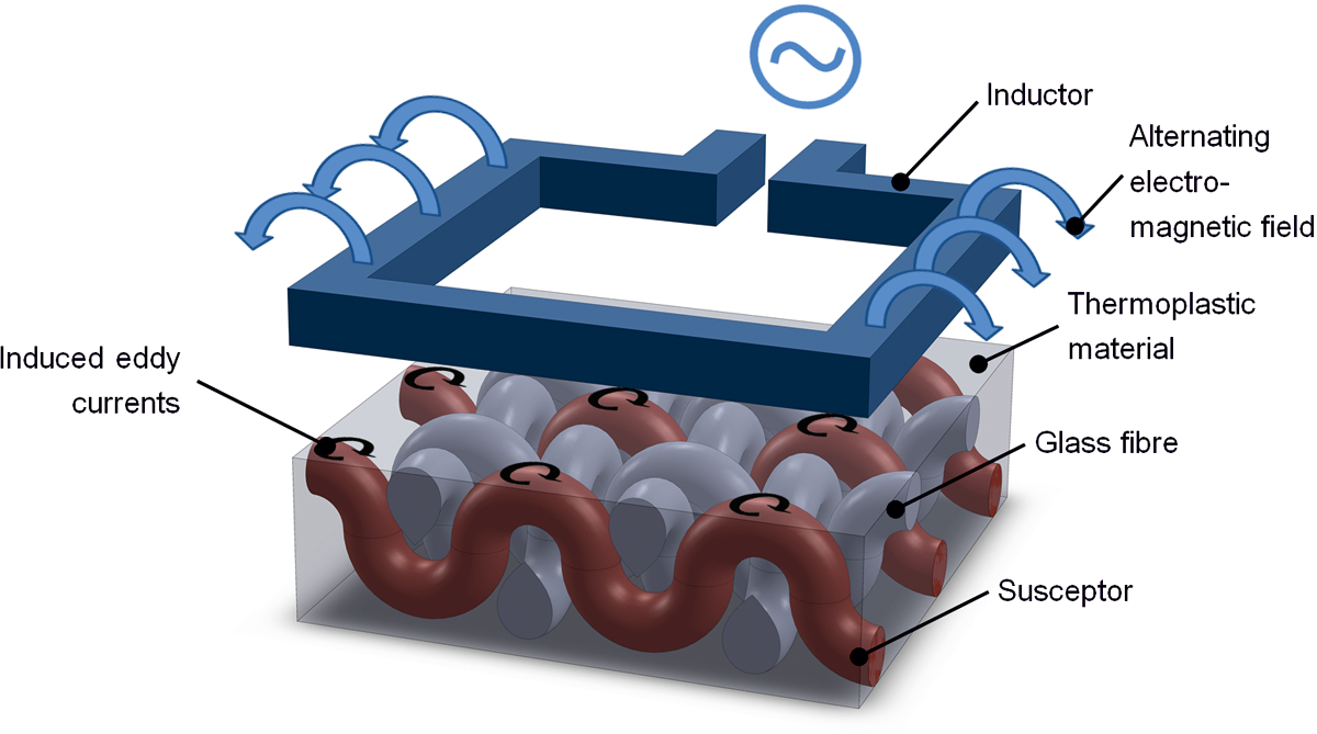
Induction heating of glass fibre-reinforced thermoplastics with an integrated susceptor.
The objective of this article
Using inductive heating for GF-reinforced organic sheets requires a complex range of knowledge. First of all, the impact of the induction system has to be considered along with the form of the inductor and the susceptor. Furthermore, detailed knowledge of these parameters is imperative for comprehensively mastering the process. This is why one of the objectives of this article is studying what the space between the semi-finished product and the inductor depends on. In turn, this insight enables a description of the space needed for effective heating. It is necessary to characterize the performance of the induction generator and frequency of the induction system on the heat development within the organic sheet. This allows estimating the induction system required for heating complex components. Finally, two different designs of susceptors (yarn and wire) will be compared in terms of their suitability for inductive heating.
The principle of induction heating
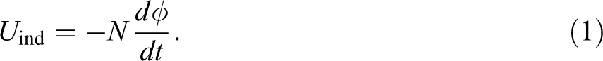
Any electrical conductor (the inductor) that an eddy current flows through is surrounded by an electromagnetic field, oscillating around a zero point at the rhythm of the eddy current. If a second electrical conductor (the susceptor) is brought into the proximity of this alternating field, voltage U ind is induced. 17 This induced voltage U ind can be calculated from the number of windings N and the change in the magnetic flow Φ in time with the law of induction:
The magnetic flow Φ can be described with:

where B is the magnetic flux density and A cos ωt is the proportion of the surface that is vertical to the lines of electrical flux. The angular frequency ω is defined by:

U ind is calculated according to the following equation 18 :

Finally, this voltage that is dependent upon the magnetic flux density B, surface area A and frequency f produces an eddy current that heats up the conductor due to the heating effect of current that develops (Joule’s heat). If the conductor is made of a ferromagnetic metal (such as iron), additional loss of hysteresis causes the conductor to heat. Non-magnetic materials such as copper, aluminium or austenitic stainless steels are exclusively heated by Joule’s heat that can be described by the following equation:

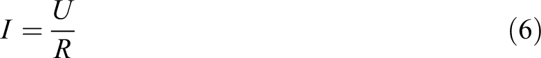
This means that the development of heat depends on time t, Ohm’s resistance R and the square of the intensity of current I. 17,18 Ohm’s law can also be used to describe Joule’s heat using the following equations:

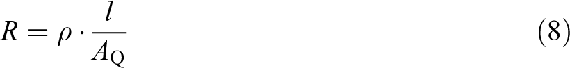
Therefore, the heat accumulating is dependent upon the electrical resistance R of the susceptor and upon the specific electrical resistance ρ, length l and the cross-sectional surface A Q of the susceptor according to the following equation 18 :
Furthermore, the heat accumulation is dependent upon the surface area A (that is penetrated by the electromagnetic lines of electrical flux), the magnetic flux density B and the frequency f. This means that the heat accumulation in the induction heating process is generated directly in the workpiece without any additional energy losses, for example, from convection, heat radiation or heat conduction. This makes it possible to attain a high level of heating output ranging up to 30,000 W/cm3 in comparison with 8 W/cm3 with conventional radiation heating. 17
Inductive heating of glass-reinforced plastics
Materials that are not electrically conductible such as GFRP cannot be heated up inductively without additional time and effort. This means that additional electrically conductible materials have to be embedded in the fibre-reinforced semi-finished products where voltage can be induced to cause the thermoplastic matrix to fuse. 6 These susceptors can be entered in powder form (such as iron powder, iron pigments or carbon nanotubes), as sheet semi-finished products (such as wire fabric, carbon fabric or carbon–nickel fleeces) or in the form of conductible continuous fibres or precision wires (stainless steel fibres, carbon fibres or copper/steel wires). 5,19 The research articles 20 –22 investigated the heating of thermoplastic fibre reinforcement with powder-shaped susceptors. A much higher frequency would be necessary for any noticeable heating in comparison with added fibre-shaped materials, thereby requiring more cost-intensive induction systems in the studies referred to. 6
Susceptors based on metallic grids are always suited for induction heating, 6,23 –25 although increased stress and voltage concentrations caused by the metallic structure are still substantial drawbacks. This is the reason why additional time and effort have to be expended to generate sufficient adhesion between the metallic grids and plastic matrix. 26 In addition, the residual stress of the component rises substantially due to the various thermal coefficients of expansion. 6
Integrating conductible fibres or fine wire materials generally has several benefits compared to the models described. For instance, additional time-consuming steps such as producing the powder, foil or fabric are no longer necessary in comparison with the other susceptor processes. Furthermore, the conductible fibres and wire materials can be processed during the textile manufacturing process (such as weaving, braiding or knitting) without substantial extra effort. Finally, this minimizes stress concentration effects using fine conductible metal fibre yarns.
The experimental set-up
All the studies were carried out with the experimental set-up shown in Figure 2 whilst positioning the specimens (GF-reinforced thermoplastic material with an embedded susceptor) directly below the inductor. There were various inductors available in several sizes for these studies (such as round and rectangular inductors). Furthermore, the electromagnetic alternating field was generated by an Eldec HFG 5 insulated-gate bipolar transistor (IGBT) high-frequency generator that works with an actual frequency of 80–420 kHz and a maximum output of 5 kW. This system works with an IGBT transistor technology and pulse package control. This means that the individual full waves targeted are turned on or off in the zero crossing of the voltage that makes it possible to largely avoid disturbing harmonics. 27 The temperature of the organic sheet was measured on the upper side of the specimen using a pyrometer (IPE 140; LumaSense Technologies, Santa Clara, CA, USA). The emissivity for the organic sheet is 93%. This reading was obtained in advance in a comparison measurement with a contact thermometer at various temperatures. In addition to the pyrometer measurement, the temperature field of the thermoplastic material was recorded and shown on the underside of the specimen with an infrared camera (Thermosensorik CMT 256 MHS, Germany). A measurement of the temperature with absolute values was not carried out with the infrared camera.
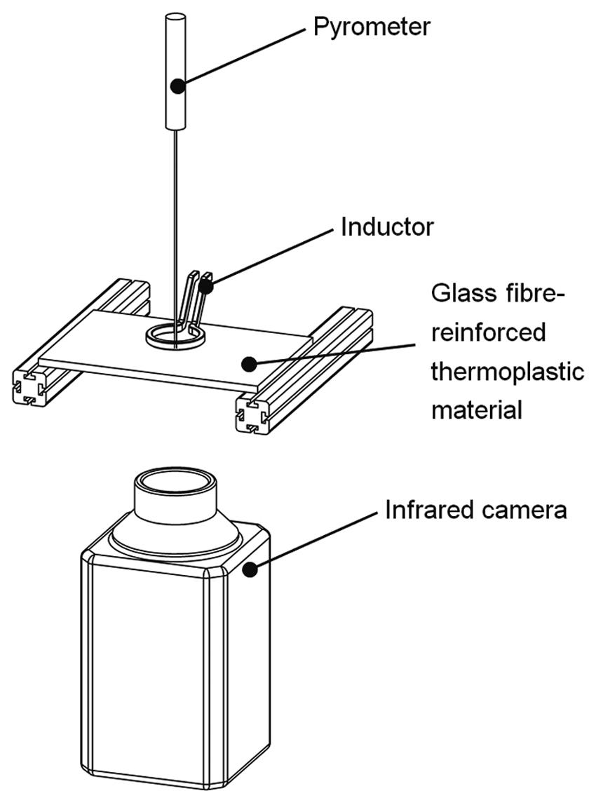
Experimental set-up for the inductive heating of glass fibre-reinforced semi-finished products with embedded susceptors.
The materials for the experiment
These studies were carried out on GF-reinforced organic sheet with a PA6-matrix (TPone PA6-GF; thickness = 2 mm; fibre volume content 40%; plain weave). Figure 3 shows the material structure with the elongated built-in stainless steel susceptor between two melted organic sheets (stainless steel spinning yarn and GF are not weaved with each other). For every sample, only one susceptor in one direction is used. A stainless steel wire (thickness = 0.1 mm, alloy AISI 316) and stainless steel spinning yarn (yarn count: Nm 11/2, alloy AISI 316L) were used for the susceptors. In a previous investigation, the conductivity of the yarn was measured. However, there was no dependency between the frequency and the conductivity in the investigated range.
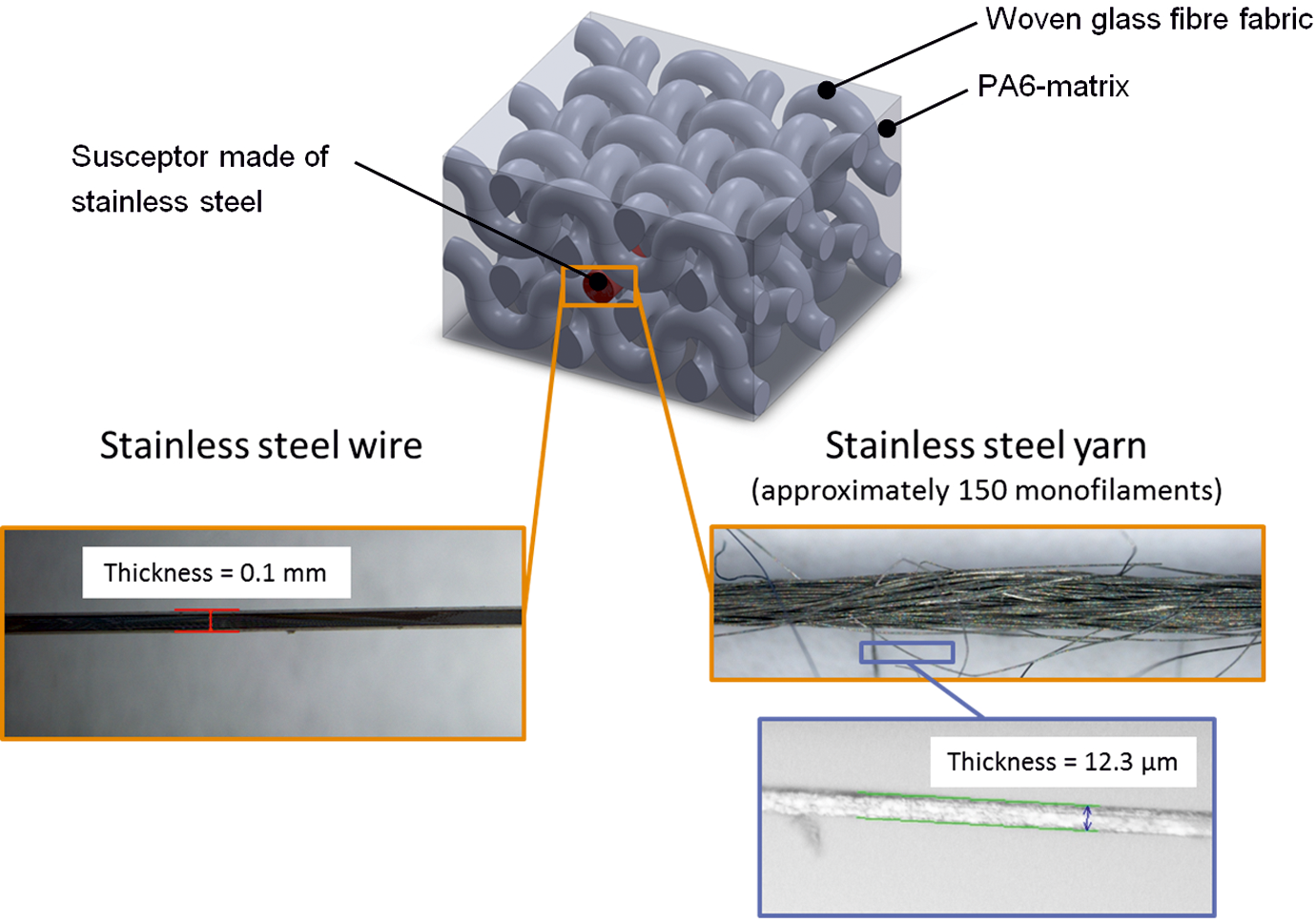
Material structure of the organic sheet with various susceptor designs.
Findings
The influence of the susceptor on heating
Induction heating with various stainless steel susceptors has the function of demonstrating the influence that the various designs have (yarn and wire refer to Figure 3) in terms of intensity of the heat accumulation. All studies were carried out with a round inductor (d = 10 mm), a space of 1 mm between the inductor and the specimen and an actual frequency of 290 kHz with a heating duration of 120 s. Furthermore, the output given by the induction generator was 86% of the maximum output. Finally, a pyrometer was used to record the temperature in the centre of the round inductor that is on the surface of the organic sheet. The temperature field was recorded with the infrared camera.
Figure 4 shows a comparison between the yarn susceptor and wire susceptor in the time–temperature diagram. It is demonstrated that using a wire-shaped stainless steel susceptor does not cause any significant heating on the organic sheet. In contrast, using a fibre-shaped stainless steel susceptor shows a maximum temperature increase of about 94 K for the organic sheet. This corresponds to an absolute temperature of 116°C.
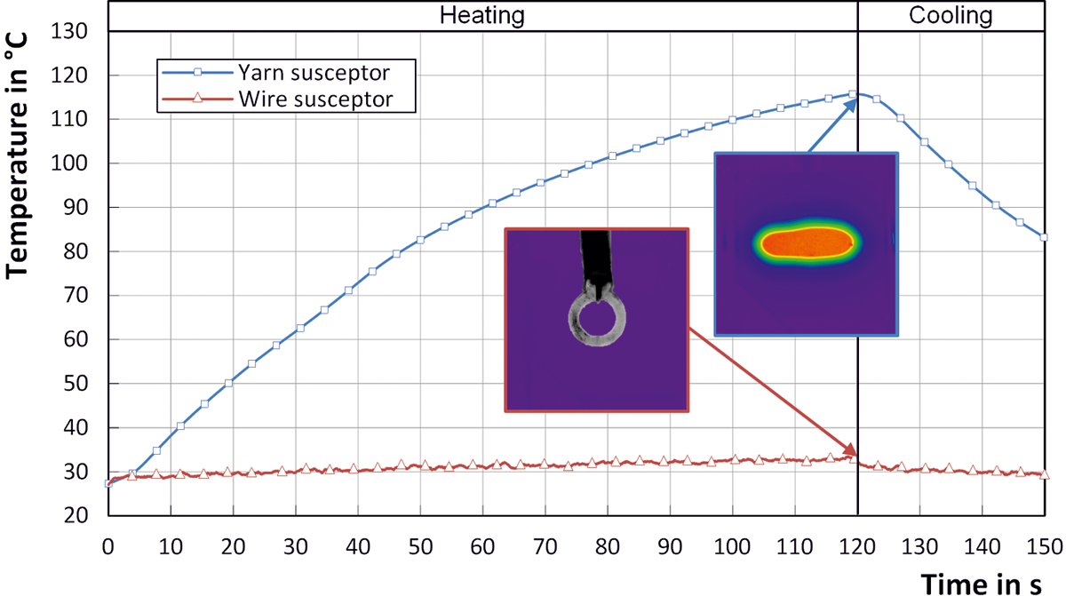
Time–temperature diagram for various susceptor designs. (round inductor d = 10 mm; P = 86%; f = 290 kHz; a = 1 mm; t = 120 s).
The difference in the behaviour between the two forms of susceptors with two major causes can be explained with this phenomenon. On the one hand, there is a higher resistance R according to equation (8) due to the much lower cross-sectional surface A Q of the individual filaments of the yarn susceptor in relation to the cross-sectional surface of the wire. This means that more Joule’s heat can be generated per individual filament compared to the monofilament of the wire susceptor. On the other hand, surface A that is penetrated by the electromagnetic lines of electrical flux is much greater because the yarn-shaped susceptor has a greater surface. Equation (4) indicates that it produces higher U ind and therefore also greater Joule’s heat loss. Therefore, using a yarn-shaped susceptor is preferable due to the greater heat accumulation. All other studies were exclusively carried out with this type of susceptor.
The influence of the space between inductor and specimens on heating
To analyze the link between the process parameters and the heating of the organic sheet in greater detail, the investigation of the space between the inductor and the specimen will be used. Measurements were made for this with a round inductor of 10 mm at an output of P = 86% for the induction generator and a frequency f = 290 kHz. The pyrometer was used to measure the surface temperature of the organic sheet in the centre of the round inductor. Figure 6 shows the maximum available temperature with the minimum and maximum readings from five measurements above the space between the inductor and the organic sheet. Here it can be seen that the greater the space, the more the maximum available temperature drops. This can be explained with the falling intensity of the electromagnetic field with increasing space between the inductor and the susceptors. The intensity of the field for a circular inductor can be described in idealized form with:
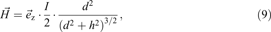
for any point P on the axis of rotation z. 28 I is the intensity of the current, d is the diameter of the inductor and h is the space between the inductor and susceptor (refer to Figure 5).
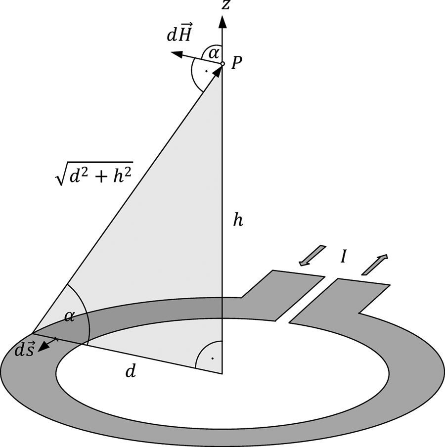
Description of determining the field at point P on the axis of rotation of a circular inductor according to Marinescu. 28
In accordance with Plaßmann and Schulz, 18 the relationship applies between the magnetic flux density B and the magnetic field intensity H in a vacuum:

Here, the constant μ0 is the magnetic field constant (or also the permeability of the vacuum). If equation (10) is applied to equation (7), and if the parameters of the cross-sectional surface A Q, frequency f and resistance R are constant, then Joule’s heat Q is only dependent upon the square of field intensity H. However, if the magnetic field intensity H is replaced with equation (9), Joule’s heat Q is simplified as follows:
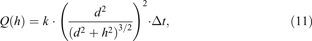
where the constant k is defined as a simplification of the intensity of current I, cross-sectional surface A Q, frequency f, resistance R and the magnetic field constant μ 0. Figure 6 shows a curve approximating equation (11) that supports the link between the theory shown and the experiment carried out since they show good agreement. The link shown between the space of the inductors and the specimen and the change in temperature shows that there are only slight temperature differences in the organic sheet with a space ranging between 0.5 mm and approximately 3 mm. This means that the space for the induction heating of the investigated thermoplastic semi-finished products should not be more than 3 mm between the inductor and the heating body.
Space to maximum temperature changing diagram (round inductor d = 10 mm; P = 86%; f = 290 kHz).
The influence of the generator output on heating
It is necessary to control the heating of organic sheets for machining in forming processes and joining operations since heating has to be over the melting temperature for the plastic deformation of the thermoplastic and the plastic has to be prevented from overheating due to incipient material damage. Changing the generator output can precisely manipulate the energy yield into the susceptor and therefore the heating of the organic sheet.
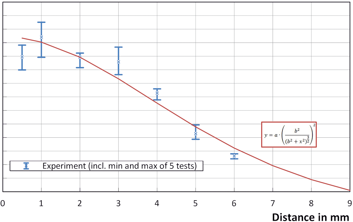
This study on various generator outputs (5%–86%) will be used to describe this link in greater detail. All the measurements were made with a round inductor of 10 mm at a space of 1 mm between the inductor and specimens and a frequency of f = 290 kHz. The temperature of the organic sheet was measured with the pyrometer on the surface of the plastic along the rotational axis of the round inductor.
Figure 7 shows the temperature for selected generators after 500 s of heating. In addition, the minimums and maximums from five measurements are entered for better illustration of the random error. Here it can be seen that the temperature drops dramatically with falling generator output. The theoretical relation can be derived between performance P and Joule’s heat Q out of the square of the dependency of Joule’s heat Q described in ‘the influence of the space between inductor and specimens on heating’ section from the field intensity H as well as by applying equation (9). This produces a square link between Joule’s heat Q and the intensity of current I:

Performance–temperature diagram after 500 s of heating (round inductor d = 10 mm; h = 1 mm; f = 290 kHz).
if the inductor has a constant diameter d as well as if there is a constant space h between the inductor and specimen. In turn, the intensity of current I is directly proportional to the adjustable performance P of the induction generator. The substantial deviations in the curve between theory and the findings obtained experimentally can be explained by ignoring the thermal constraints such as convection, heat radiation and heat conduction. Especially with temperature changes over 60 K, it can be clearly seen that the difference between the plastics and its environment is due to the increased temperature gradient and the increase in energy yield to the environment.
The influence of frequency on heating
The frequency at which the current changes its direction in the inductor has a decisive influence on the heating behaviour of the component. For example, it is possible to measurably increase the efficiency of the induction system with an actual frequency adapted to the workpiece, 17 whilst an experimental study of frequency dependency can only be carried out with one or several induction systems with a wide and adjustable band of actual frequencies. In contrast, it is not possible to freely select a frequency with the available frequency generator due to the automatic adjustment to each inductor attachment and the material to be heated. The numerical simulation of the heating process makes it possible to significantly limit the time and cost-intensive experiment. This is the reason why the frequency dependency of the heating process will be analyzed in greater detail in the finite element (FE) software environment ANSYS Workbench below (Version 14.0.0). The implied software solver allows robust implementation of applications with electrical–thermal–mechanical field couplings as might be expected with induction heating. 27,29
Setting up the model in the FE software ANSYS Workbench
The numerical simulation of the inductive heating process calls for forming the composite material including the susceptor and the inductor and surrounding air. Figure 8 shows the simplified FE model that was set-up as per the mode of procedure (refer to Figure 2) in the simulation environment. Building a semi model is sufficient due to the axial symmetry of the fibre-reinforced plastic, susceptor and inductor. This guarantees lower computing times compared to a full model. Furthermore, the complex fibre-shaped susceptor was mapped with a simple cylindrical substitute model, whilst the FE model was set-up with three-dimensional volume elements (SOLID236 and SOLID87). Also the organic sheet with the GF weave structure was simplified to one material and one thermal conductivity. Thermal properties like radiation and convection were set on the surface of the organic sheet.
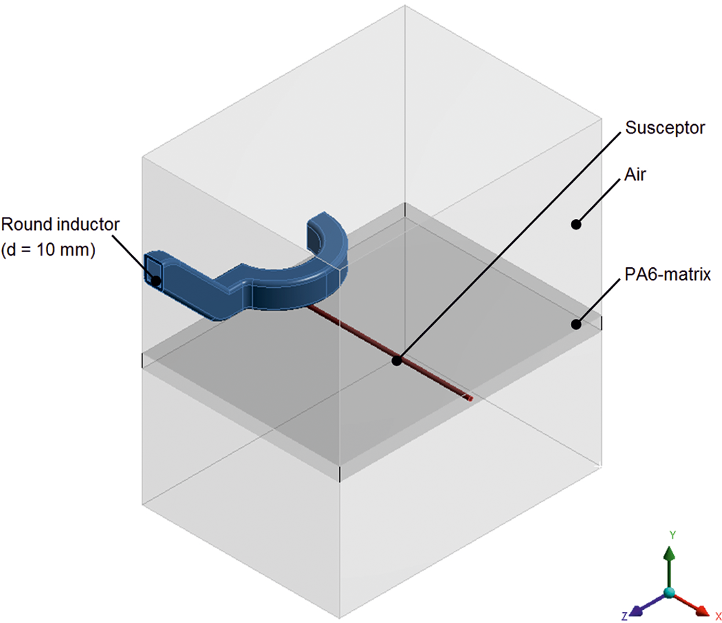
FE model of the inductive heating process. FE: finite element.
Figure 9 shows a schematic diagram of coupling implementation between the thermal and electromagnetic field in ANSYS Workbench and the simulation curve carried out in a sequential calculation run-through. Furthermore, the eddy current formation and power density (Joule’s heat) are calculated at the beginning of the simulation in one harmonic step in the calculation at a constant frequency. This is necessary because the change speeds of current and temperature are several dimensions apart, which means that a holistic transient calculation does not provide any results. 29 Now the temperature field is calculated transiently in the second step of the calculation using the Joule’s heat that was ascertained. This simplified calculation done one step after another is possible without a loop run-through since the material properties (such as the temperature dependency of the specific electrical resistance in the temperature range to be studied up to 300°C) only has a slight influence on heat development.
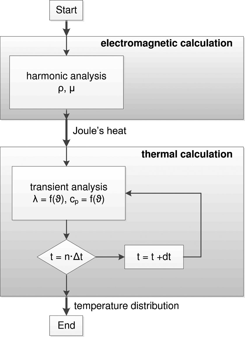
Simulation cycle in ANSYS Workbench following the method described by Wrona. 27
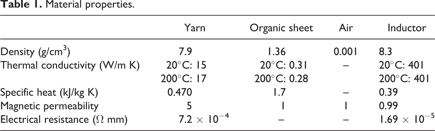
Table 1 shows the material properties used in the FE model. The model is based on the assumption of constant electrical resistance for the yarn for different frequencies.
Material properties.
Verifying the model
Figure 10 shows the simulated time–temperature curve for heating the organic sheet in comparison with the data acquired in the experiment. To calibrate the model, especially the homologous yarn model, the magnetic permeability of the yarn has been changed. The temperature is measured in the centre of the inductor on the surface of the thermoplastic (refer to the lower right-hand side of Figure 10). Here, it can be seen that the temperature curve of the simulation is in good agreement with the one of the experiment. Finally, the simulation model maps the maximum obtainable temperature very precisely after 120 s of heating.
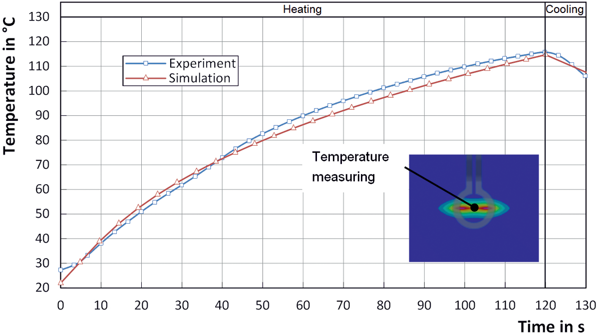
Comparison of the time–temperature diagram between the simulation and experiment (round inductor d = 10 mm; h = 1 mm; P = 86%; f = 290 kHz).
Figure 11 shows a top view of the comparison between the temperature fields of the experiment and simulation for individual heating up time points between 20 s and 120 s. The zones filled in red represent areas of high temperature and the blue zones represent areas of low temperature. The excellent replication of the hot temperature zones below the inductor (refer to the white markings in Figure 11(a) and (b)) can be seen. The intensity of the electromagnetic field is strongest in this zone, which causes it to heat up quicker than in other areas. For instance, it can be seen how the high-temperature zone spreads in the direction of the centre of the inductor at the point in time (Figure 11(b)). This can also be excellently mapped by the simulation. The radial increase in the hotter temperature range in Figure 11(c) to (f)) is clear. The comparison between the simulation and experiment also shows excellent agreement of this heat distribution (refer to the white markings in Figure 11(c) and (f)).
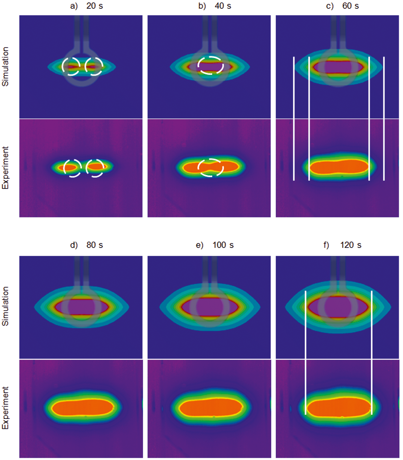
Comparison of the temperature field between the simulation and experiment (round inductor d = 10 mm; h = 1 mm; P = 86%; f = 290 kHz).
The findings of the numerical study
Figure 12 shows how the numerically calculated temperature in the organic sheet depends on the frequency for the inductive heating process. Furthermore, a square link between the frequency and temperature with the drawn approximation curve can be seen. This relationship can also be proven by equation (7) with constant magnetic flux density B, constant resistance R and constant surface A. This means that there is a square link between Joule’s heat losses and frequency for inductive heating:
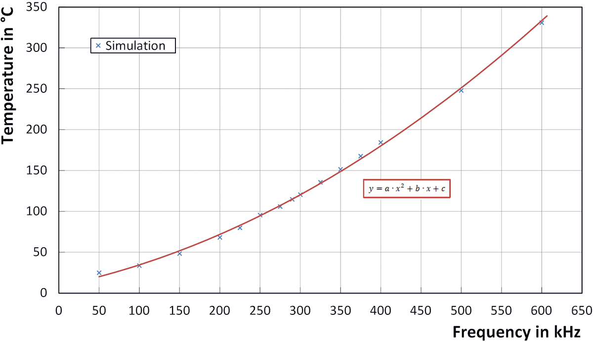
Numerically calculated frequency–temperature diagram.
Any economically meaningful usage of thermoplastic fibre-reinforced semi-finished products calls for not only low prices for raw materials but also brief cycle times for the heating and forming process. This is why the briefest heating time for the organic sheet to the processing or melting temperature is of the utmost importance. Figure 13 shows the frequency–time curve until the surface temperature of 114°C is reached for various frequencies. It can be seen that any increase in the generator frequency causes a substantial reduction in the necessary heating up time. If, for instance, the actual frequency of 290 kHz used is increased to approximately 600 kHz, the heating phase is reduced by approximately 100 s. Therefore, the actual frequency of the induction system is a very decisive aid for the efficiency of heating process. However, the experimental evidence of this has yet to be provided.
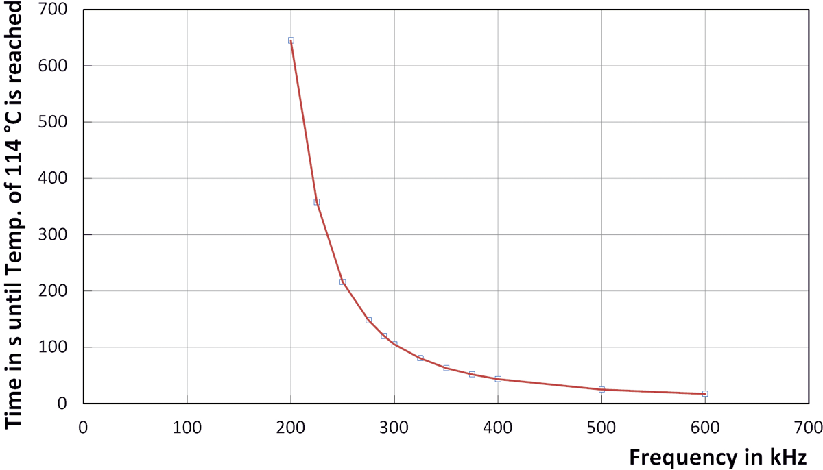
Frequency–time diagram.
The influence of the geometrical dimension of the conductor on heating
The maximum obtainable temperature of the organic sheet is important as well as the formation of the temperature distribution on the level. Melting just a small area around the joining zone is beneficial, especially for joining operations to maintain the strength of handling the component. The idea is to form homogenous temperature distribution in the entire welding zone. The selection of inductor geometry and therefore the field intensity for the location have the greatest influence on the temperature in the heating zone. All the studies on the form of the inductor were carried out with the space between the inductor and the specimen being 0.5 mm and with the induction system performance of P = 86%. The geometries of the inductors were selected to ensure that the adjusting frequency varies around ±10 kHz. This means that it can be excluded that the study was influenced by various frequencies.
Figure 14 shows various inductor geometries and the temperature field emerging after 120 s of heating. An elliptic heating zone develops on all inductor forms due to the position of the yarn-shaped susceptor. This also demonstrates the even formation of the temperature field with the round inductor at a diameter of 10 mm over a large surface. The temperature fields of the round inductor of 15 mm and the two rectangular inductors have lower temperatures in the marked zones. Under certain circumstances, this can mean that the melting temperature of the thermoplastic matrix will not be reached so that the joining zone cannot be completely melted.
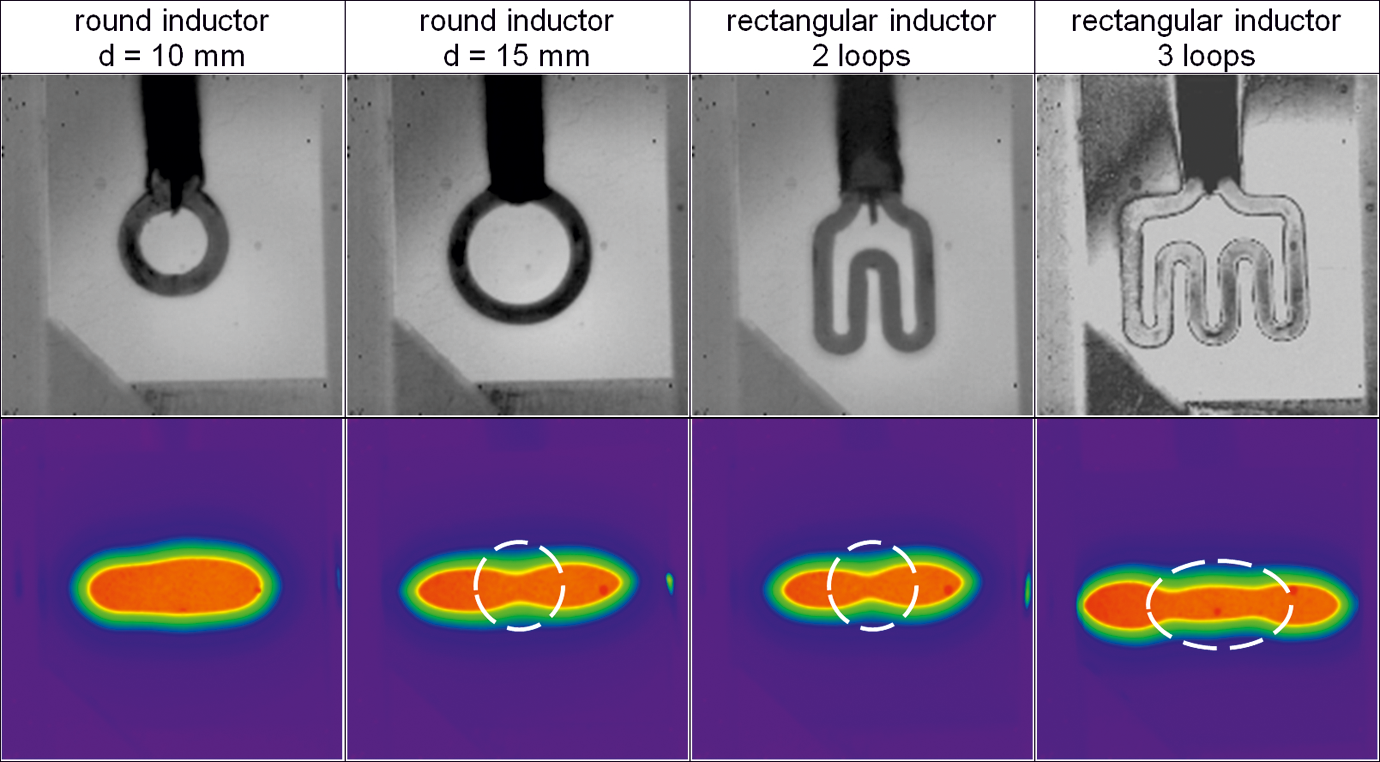
Inductor geometries studied with the temperature field emerging after 120 s of heating.
Figure 15 shows a comparison between the four inductor geometries in terms of the temperature change that can be achieved after 120 s of heating with the maximums and minimums of five experiments each. The point with the highest temperature was assessed on the plastic surface for each individual sample geometry. It can be seen that the round inductor with a diameter of 10 mm has reached the highest temperature change of 90 K. In contrast, the round inductor with a diameter of 15 mm only reaches 63%, whilst the rectangular inductor with 2 loops only reaches 78% of the maximum temperature change. However, it was possible to achieve a temperature increase of 39 K with the rectangular inductor with 3 loops. This equals 44% of the maximum temperature of the round inductor of 10 mm. The low temperatures compared to the round inductor of 10 mm can be primarily attributed to the lower intensity of the electromagnetic field that has a local influence on the susceptor.
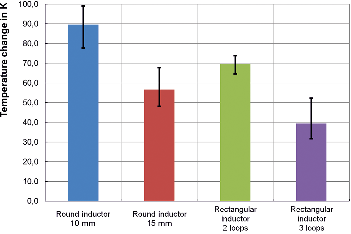
Impact of inductor geometry on the maximum temperature after 120 s of heating (a = 0.5 mm; P = 86%; f = 290 kHz).
Summary
This article shows the dependency of the type of susceptor, the geometric shape of the inductor and the influence of the process parameter space between the specimens and inductor, generator output and frequency of the induction system with reference to the inductive heating behaviour of a thermoplastic fibre-reinforced semi-finished product. The heating experiments from two different susceptor designs (yarn and wire) were used to demonstrate that the wire-shaped susceptors used are not suitable for heating GFRPs. In contrast, susceptors consisting of fibre-shaped stainless steel yarns showed good heating behaviour. Furthermore, it could be demonstrated that the maximum achievable temperature of the organic sheet does differ in any significant fashion up to a space of 3 mm between the inductor and the specimens. In any event, greater spaces should be avoided due to the falling temperature coefficients.
This experimental study of various generators indicated that it is possible to systematically control temperature with the adjustable performance of the generator. The numerical simulations were used to analyse in greater detail the dependency of the frequency of the induction system on heating using a model per the experimental mode of procedure. Furthermore, verifying the simulation with the experiment for the time–temperature curve and forming the temperature field indicate excellent agreement, making the study of frequency dependency possible. Beyond this, a graph assessment of the various simulation run-throughs was able to demonstrate a square link between frequency and the maximum obtainable temperature. This proved that the actual frequency of the induction system used is a decisive parameter for designing the heating process. Finally, different inductor attachments were used to analyse in greater detail the effect of the form of the inductor on the forming temperature field and on the maximum achievable temperature change. It has been shown that a round inductor with a diameter of 10 mm shows the most favourable heating behaviour for the organic sheet used.
The studies described in this article showed promising findings in terms of heating small local surfaces using one susceptor. Further studies with more than one susceptor in the plastic matrix will demonstrate the potential and the efficiency for heating larger surfaces.
Footnotes
Acknowledgements
This work was performed within the Federal Cluster of Excellence EXC 1075 MERGE Technologies for Multifunctional Lightweight Structures and supported by the German Research Foundation (DFG). Financial support is gratefully acknowledged.
Declaration of Conflicting Interests
The author(s) declared no potential conflicts of interest with respect to the research, authorship, and/or publication of this article.
Funding
The author(s) disclosed receipt of the following financial support for the research, authorship, and/or publication of this article: This research is financed with the help of the Federal Cluster of Excellence EXC 1075 MERGE from the DFG.