
Abstract
For the manufacturing of mechanically strong and lightweight composite aerostructures reinforcement materials (e.g. carbon fibers, CFs) are the most convenient way. Therefore, sizing of carbon fibers is crucial for guiding them into service by protecting the CF’s surface. In this study, a novel sizing agent was developed and effects of this sizing on CFs’ physicochemical as well as surface properties were investigated. The impact on the fiber-matrix interphase behavior was analyzed. Results reveal that the surface free energy of CF was increased from 5.67 mJ/m2 to 13.13 mJ/m2 through sizing by enhancing the wettability property of CF. In addition, surface topography analyses indicate that the surface roughness Ra is 3.70 ± 2.59 nm for neat CF; 1.01 ± 0.65 nm for Polyetherimide (PEI) sized CF; and 1.71 ± 1.14 nm for PEI-Polyether ether ketone (PEEK) sized CF. Finally, it was concluded that an increment in the wettability can be related with chemical changes on the fiber’s surface.
Introduction
There are continuing studies on the development of coating materials for enhanced CFs in the context of reinforced composites. However, with the current know-how, proposing a way to improve CF’s physicochemical properties individually (i.e. thermal endurance, mechanical strength, chemical resistance, etc.) is lacking. Various studies based on the interfacial behavior in composites, especially considering thermoset-matrix based composites, exist.1–11 However, there is a need for addressing the sizing material for CFs to enhance physical, chemical, and mechanical properties. In addition, the literature is insufficient in terms of integration of the achieved improvement in physicochemical properties into CF reinforced thermoplastic (TP) composite (CFRTPs) materials. In this sense, there is a lack of using a wide range of matrix materials since many studies are based on thermoset matrix materials such as epoxy resins.1,2,4–8,10–16 Unlike thermosets, thermoplastics provide significant advantages such as recyclability and remolding in addition to lightweight with high performance.17–19 On the other hand, current thermoplastic based composites with epoxy-coated CFs suffer from de-bonding between fiber and matrix as well as low thermal stability at elevated temperatures due to the present epoxy coating.1,20–24 As commercially used CFs cannot provide the desired adhesion between fiber and thermoplastic matrix (i.e. PEEK) there is a need for novel sizing materials.25–30 Therefore, delamination problem occurs in fiber reinforced composites due to low adhesion between matrix and fiber. 31 Thus, a chemically and physically compatible sizing agent was utilized around CFs to obtain optimized wettability.
In this study, the design and development of a polymeric sizing material, which is compatible with the surface of CF for the purpose of avoiding any separation between fiber and coating material, was focused on. To do so, surface chemistry, roughness, and crystallinity were studied. Furthermore, effects of the coating on CF’s thermal and mechanical properties were analyzed. Afterwards, interfacial locking between surfactant and polar coating of CFs within the TP matrix was also investigated.
Experimental
In this work, PEI and its solution blend PEEK were chosen as alternative sizing agents for CF reinforced (CF/PEEK) composites. The aim for using this type of composite is that CFRTPs have a significant potential to be applied in the aerospace industry instead of metals and thermoset composites as it is a highlighted need to reach high performance/weight ratios in aircrafts in combination with properties like recyclability.32–37 The elimination of present coatings in commercial CFs via desizing methods (e.g. thermal, chemical) is needed as epoxy is not compatible with the TP matrix and therefore, causes delamination in CFRTPs. The thermal desizing method was used in contrast to chemical etching since the CF surface has to be prevented from any possible damage physically and chemically.
Materials
Granular PEI with approximately 30,000 g/mol effective molecular weight, 3 mm nominal granule size and 217°C glass transition temperature was obtained from Sigma-Aldrich, USA. Likewise, powder PEEK with a mean particle size of 80 µm was obtained from Sigma-Aldrich, USA. Aerospace grade 12K T700G standard modulus CFs which are originally coated with 0.5 % epoxy from Toray Industries, Japan, were used as untreated CF. Moreover, chloroform was used to dissolve sizing agents and sodium dodecyl sulfate (SDS) was used as a cationic surfactant in order to achieve binding of the sizing material onto the CF surface through hydrophobic interactions. In the consolidation part, PEEK films (APTIV 1000) from Victrex, UK, were used.
Preparation of Sizing Agents
Regarding the solvent-based sizing agent, two batches were prepared by using PEI only and the solution blend of PEI & PEEK.
1st batch: 0.5 wt% of granular PEI were homogenously dissolved in chloroform. It was observed that dissolving PEI was a problem to be handled (i.e. toluene, isopropyl alcohol, dimethyl sulfoxide and ethanol were studied, but they were not useful for dissolution of the main sizing agent). Thus, halogenated polar solvents, particularly chlorinated ones, were found successful to dissolve PEI. Later, 10 wt% SDS stock solution was used as a surfactant in the concentration of 0.5 wt%. The optimum concentration for using a surfactant for the preparation of an aqueous dispersion of a TP sizing agent for CF by emulsion/solvent evaporation is indicated between 0.3 and 1 wt%. 25 Hence, 0.5 wt% of SDS was prepared from the stock solution by using the formula; M1V1 = M2V2 where the notation “1” refers to the situation before the dilution and “2” refers to the situation after the dilution while “M” indicates the molarity and “V” indicates the volume. The addition of the surfactant was carried out drop by drop during mechanical stirring of the PEI solution. Later on, the stirring of the final solution continued for 12 h in order to obtain the first sizing agent homogenously.
2nd batch: 0.25 wt% of powder PEEK and 0.25 wt% of granular PEI were blended by solution mixing in chloroform. Later, 0.5 wt% SDS surfactant was added into the solution. Finally, a surfactant stabilized emulsion was obtained as second sizing agent after 12 h mechanical stirring was applied.
Sizing Treatment of CFs
Various sizing techniques, such as electrodeposition, spray coating or bath coating are performed to improve surface properties and also, eliminate the excess charge accumulation on materials during manufacturing process.5–7,9,38–40 In this study, the dip coating method was utilized for the sizing treatment of the CF bundle. However, a heat treatment was applied onto CF beforehand. Thus, any present coatings or impurities were removed. At this stage, the degradation temperature of CF was determined through Thermal Gravimetric Analysis (TGA) in order to avoid causing any harm to the CF itself. As a result, the application of heat up to 450°C for the thermal desizing of any current coating (e.g. epoxide) was considered safe in terms of chemical and physical unity of the CF. Consequently, CF bundles were desized in a radiant oven at 400°C for 10 min with 10°C/min heating and cooling rate under air conditions. Hence, neat CFs were obtained. Later, sizing treatment was carried out through dip coating for both 1st and 2nd batches separately. After the coating, the CF surface dried at room temperature meanwhile the remaining chloroform in the sizing agent evaporated off. Afterwards, rigid sized CF bundles were obtained.
Fabrication of CFRTP Laminates
Consolidation of CFs with the PEEK matrix was carried out in order to obtain composite laminates. Desized and sized CFs were impregnated into the thermoplastic matrix, i.e. PEEK, by use of a hydraulic hot press. In the manufacturing of CFRTP composite specimens, eight carbon fabrics woven by desized or sized CFs, and nine layers of PEEK films, each measuring 11 × 11 cm2, were stacked alternately. These piles were fastened onto a press table and compressed using the hydraulic hot press (Langzauner, AT) at 395°C and a pressure of 2.5 MPa for 25 min. Subsequently, samples were cooled to 100°C at a rate of 10°C/min while maintaining constant pressure. Resulting composite laminates contained a CF volume fraction of 40 % for each sample.
Characterization
For the characterization of CFs, a thermal study was conducted via thermal gravimetric analysis (TA Instruments TGA Q500, USA). A furnace (Thermolyne, 48,000, USA) was used for the desizing of CFs. The morphology was determined using an environmental scanning electron microscope, ESEM and energy dispersive X-ray, EDX (Quanta 200 FEG, Netherlands). Chemical and elemental analyses were carried out using X-ray photoelectron spectroscopy, XPS (Thermo Fisher Scientific, USA). Topography analysis was performed using the PSIA atomic force microscope (AFM) Suwon from South Korea. Surface roughness values were also examined from four different points on the same sample by a 3D laser scanning microscope (Keyence VK-X100, Japan). Contact angle (CA) measurements in sessile drop mode were performed using Dataphysics OCA 20, Germany, with distilled water in a dosing volume of 1.5 μL and a dosing rate of 0.5 μL/s. Corresponding measurements were taken from fiber bundles positioned onto a glass slide while the fiber amount was taken into account. Thus, CA measurements were obtained directly from carbon fibers. Results belong to neat and sized CFs. Afterwards, changes in surface free energies (SFE) were compared between neat and sized CFs. X-ray diffraction (XRD) patterns were recorded using an X-ray diffractometer (X’pert pro MPD, PANalytical, UK). Crystallography measurements were conducted via X’pert HighScore Plus. Tensile tests on composites comprising untreated and appropriately sized carbon fibers were conducted under ambient conditions using a mechanical tester (ITW, USA) equipped with a 100 kN load cell. Mechanical properties of untreated, desized and sized CFs were analyzed according to the ASTM D3039 test standard. Tensile tests with an extension rate of 2 mm/min and strain gauges were performed on bundles containing nine carbon filaments for untreated and desized CFs. In addition, tensile tests were also applied onto desized and sized laminated composite samples where specimen dimensions were 50 × 4 × 1 mm3. The gauge length was fixed to 50 mm for all bundles containing carbon filaments and 10 mm for neat and sized laminated composite samples. All tensile tests were repeated three times after balancing load cell and signal to noise ratio in order to maximize accuracy. Thus, bundles were studied to investigate the effect of thermal desizing on mechanical properties while laminated composites were studied in order to analyze effects of the novel sizing.
Results and Discussion
Effects of Preheating
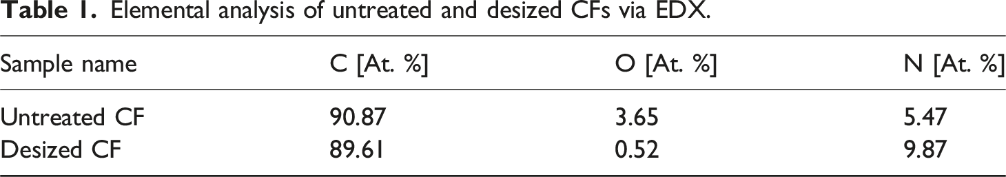
A thermal desizing process was carried out to untreated epoxy-coated Toray T700G CF at 400°C for 10 min with 10°C/min heating and cooling rate under air conditions. As a result, the sizing process onto neat CF bundles was utilized. Afterwards, epoxy-coated CFs were compared with CF samples after the desizing process in order to analyze if any change has occurred in the chemistry of CF bundles due to the coating. In this sense, elemental and morphological analyses were carried for as received epoxy-coated (i.e. untreated) and neat (i.e. desized) CFs by EDX and ESEM, respectively.
Elemental analysis of untreated and desized CFs via EDX.
The surface morphology of CF changed after the thermal desizing application. The surface roughness increased after heat treatment onto CF as can be observed in Figure 1 since desizing took place. Thus, the result facilitates the binding of the sizing agent throughout the CF surface. As a consequence of these elemental and morphological analyses, it can be concluded that the application of heat treatment serves the effective sizing purpose. SEM images of untreated (a) and desized CF (b).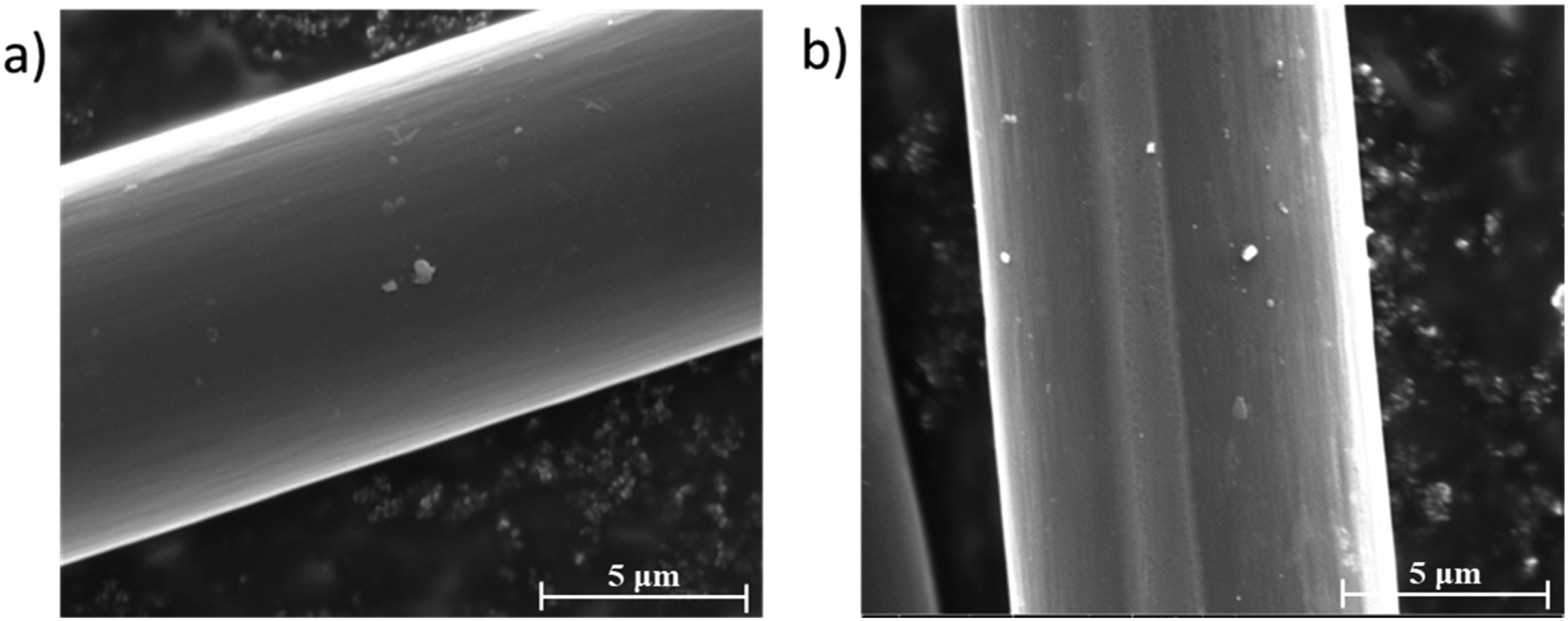
The average maximum stress for untreated and desized CF bundles were obtained as 26.9 ± 3.8 MPa and 24.4 ± 3.2 MPa, respectively. Furthermore, the average maximum loads that CF can bear were measured as 1345 ± 176 N for untreated and 1218 ± 158 N for desized CF bundles as shown in Figure 2 where cascadingly failing CFs are observable. Thus, the average bearable force decreases by 9.4 % after desizing due to the elimination of the epoxy. However, both results overlap with regard to the standard deviation. Displacement/force results for untreated and desized CFs bundles.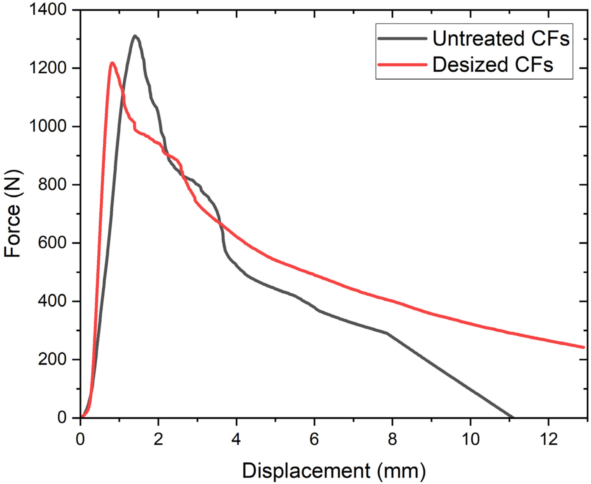
Microstructure of Modified CF
Chemical and morphological analyses of CF surfaces were carried out in order to show the presence of coating after sizing of neat CF. During the sizing process it was observed through Raman spectroscopy that without using the surfactant, a compatible sizing could not be achieved. Therefore, SDS was used as a surfactant for achieving the desired interaction, i.e. binding between the inert CF surface and polar sizing agent. Hydrophilic interaction takes place between the hydrophilic head of the cationic surfactant SDS and nitrogen side of PEI. The pretreatment by the surfactant eliminates potential phase separation between sizing material and inert CFs by reducing their surface tension. As nitrogen bridges are formed, surfactant directed adhesion between sizing agent and pretreated CF was achieved. This result was confirmed by SEM analysis (Figure 3). SEM images of neat CF (a); PEI sized CF (b); PEI-PEEK blend for sizing of CF (c) and cross-sectional images of neat (d) and sized (e) fibers.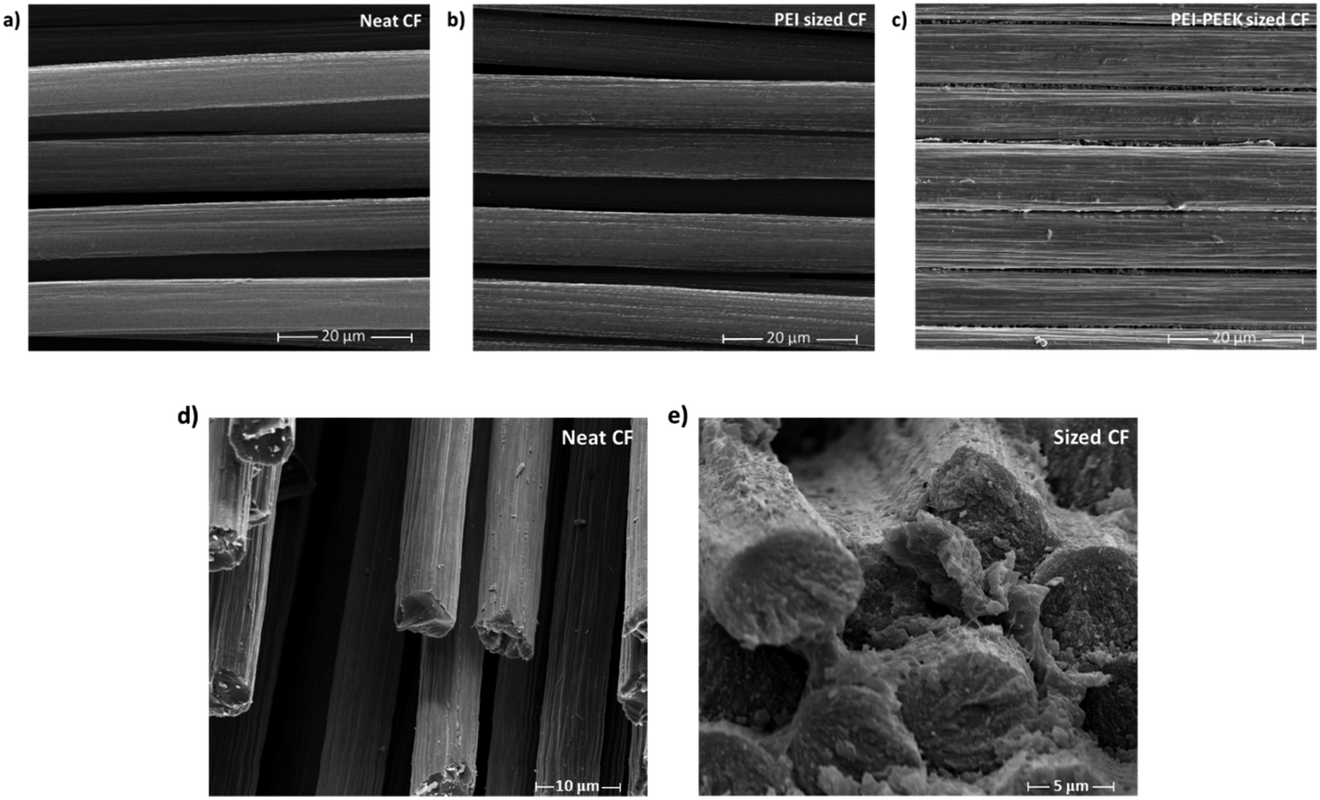
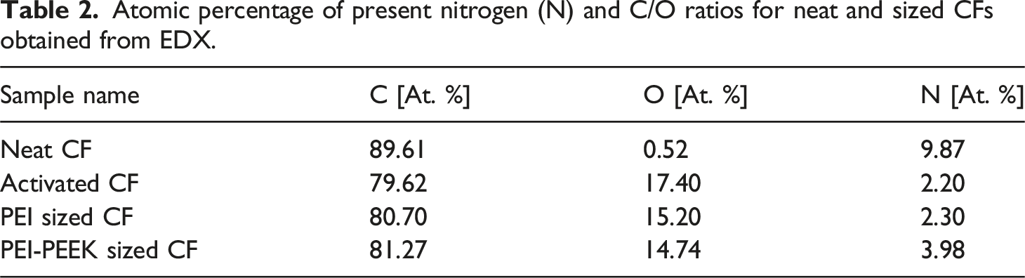
Atomic percentage of present nitrogen (N) and C/O ratios for neat and sized CFs obtained from EDX.
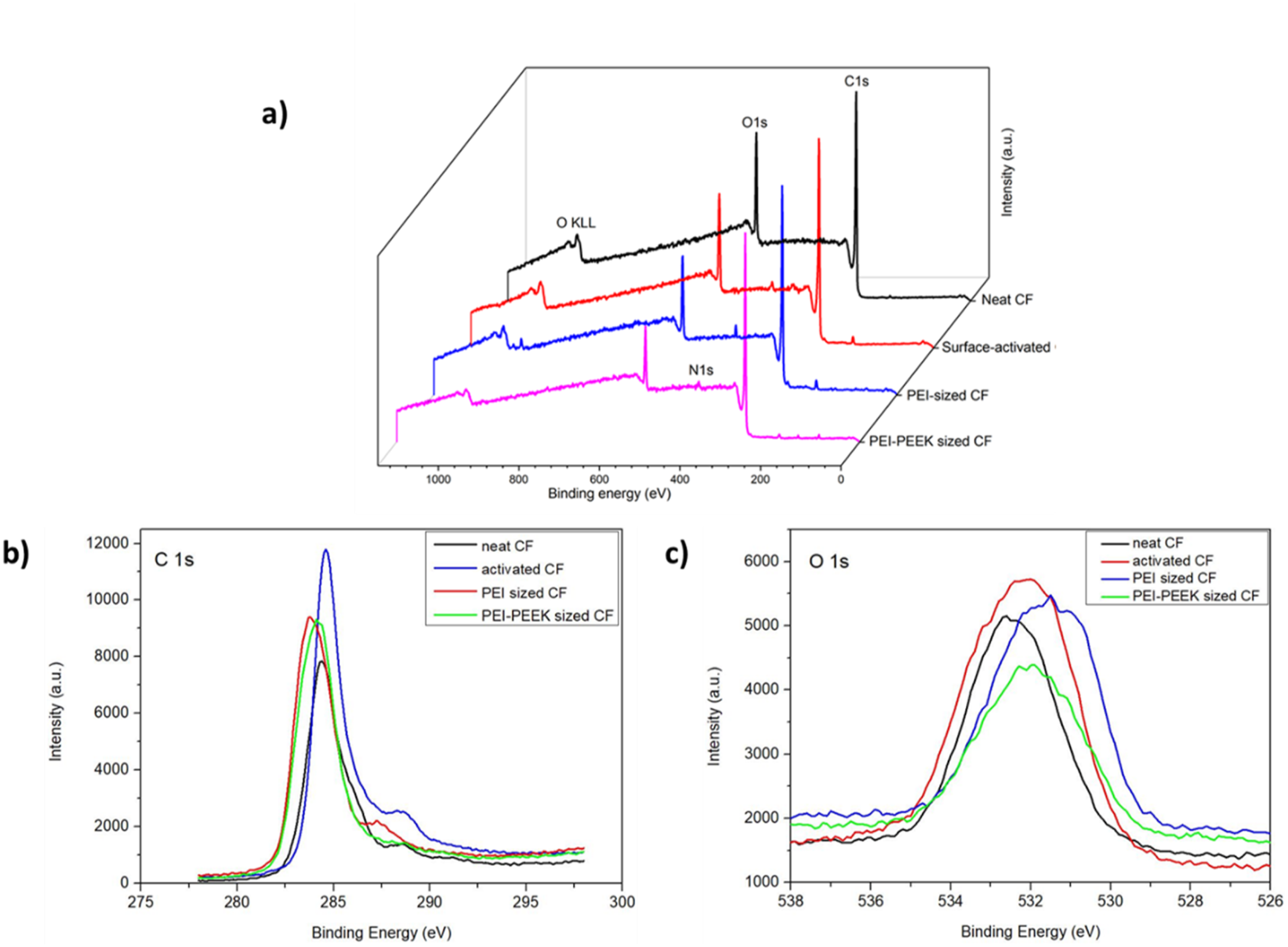
XPS survey (a), high resolution carbon (b) and oxygen (c) spectra of neat, surface-activated, PEI-sized and PEI-PEEK sized CF.
The atomic percent of elements calculated via EDX indicates that the oxygen content increases when surfactant treatment and sizing was applied onto CFs because of present oxygen atoms in chemical structures of coating materials. On the other hand, the decrease in nitrogen amount indicates that coating of neat CF with surfactant and sizing by PEI or PEI-PEKK act as a protective layer against environmental free elemental atoms. Results are summarized in Table 2. Of interest, results obtained by EDX correspond to XPS measurements.
Chemical analyses for sized and surfactant treated CFs (i.e. surface activated CFs) were carried out via XPS depicted in Figure 4. C–C and C–O bonds can be identified at around 283 – 286 eV while peaks at 400 eV show nitrogen bonds.42,43 C = O, C–OH and O = C–O bonds can be observed in the spectra at approximately 530 – 534 eV. 44 Furthermore, a change in the oxygen content after sizing was revealed through atomic calculations (see Table 2).
Morphology of Modified CF
It was observed that sizing of CF changes the fiber’s morphology (Figure 5). Neat fibers were observed as smooth and separated while the coating material filled voids between CFs with the required amount of sizing polymer. Moreover, there are some agglomerations of sizing agents on the fibers’ surfaces. The expected sizing thickness surrounding a single CF is 0.6 μm for both sizing agents as shown in Figure 3(e) while the interaction volume for ESEM and EDS was 2 μm. In addition, the surface topography of untreated and modified CFs was analyzed via an AFM while results are presented in Figure 5. AFM height profile and 3D laser scanning microscopy of neat CF (a), (d), PEI sized CF (b), (e), and PEI-PEEK blend sized CF (c), (f). Note that image flattening was carried out by applying the Gwyddion software due to the diameter of the fibers and the image size of the AFM experiment.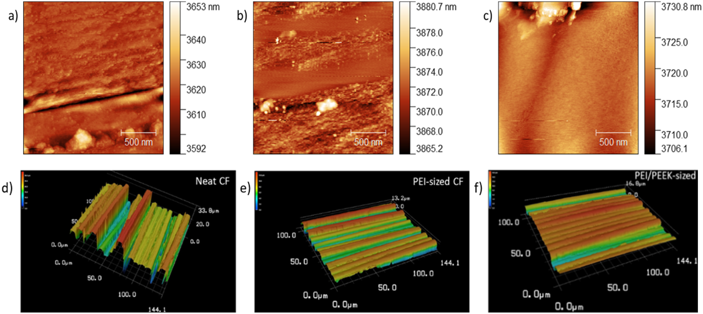
The average surface roughness Ra was determined for each sample by two different methods as summarized in Sect. 2.5 in order to validate the results. The Ra value is 3.70 ± 2.59 nm for neat CF; 1.01 ± 0.65 nm for PEI sized CF; and 1.71 ± 1.14 nm for PEI-PEEK sized CF. Hence, coating of thermally desized CFs by emulsion of a polymeric sizing agent and surfactant makes the CF surface slippery by decreasing the average surface roughness. The reason for this result is based on the influence of the surface roughness on van der Waals interactions relating with agglomerates. Remarkably, this effect might be favorable for the manufacturing process of composites. 21 Even at higher temperatures where the sizing material softens, the roughness of the surface still plays a significant role in facilitating mechanical interlocking and chemical bonding between fiber and matrix. While the sizing may soften, the underlying roughness can still provide sites for enhanced adhesion and improved load transfer between fiber and matrix. 30 Also, even if the sizing softens, a rough surface can promote better wetting and penetration of the matrix material into the fiber, leading to improved impregnation and distribution of the matrix within the composite. 31 Moreover, the roughness of the fiber surface continues to impact the interfacial shear strength between fiber and matrix even at higher processing temperatures. Mechanical interlocking at the interface facilitated by the surface roughness remains important for enhancing the overall strength and durability. 32 Furthermore, surface roughness variations can affect the development of residual stresses within composites, even with higher processing temperatures. Thus, controlling the surface roughness can help mitigate the formation of stress concentrations and ensure more uniform distribution of stresses throughout the composite structure. 33 The high Ra of neat CF might be the result of present voids between fibers while the sizing material fills all voids which decreases the average surface roughness. Thus, the influence of the roughness of the sized fibers observable in SEM results summarized in Figure 3 is small in comparison to voids between fibers in neat CF. Note that with regard to the wettability, surface characteristics of the fibers are dominated by the chemistry of the sizing agent since a sufficient surface roughness is achieved beforehand.45–49
Moreover, electrostatic properties of CF are other parameters of relevance. Since the sizing surrounding the fiber sample prohibits electrostatic properties of CFs, the Ra value for the sized CFs is found to be smaller in comparison to neat CF. Charge accumulation on neat fibers was eliminated by coating since the sizing material plays a role as barrier surrounding CFs in order to protect their surface against environmental conditions.
It was observed that surface roughness affects the wettability, i.e. the surface polarity is enhanced throughout the sizing.39,40 CA measurements presented in Figure 6 indicate that when neat CF is sized, the hydrophilicity of CF’s surface is enhanced through the increment in surface free energy from 5.67 mJ/m2 to 13.13 mJ/m2. Hence, the wettability of the CF surface has been improved by the polymer matrix. Therefore, the compatibility of the reinforcement material (CF) with the TP matrix (PEEK) increases with the sizing (which is of major relevance for industrial applications5,25). Note that CAs of neat PEI and the PEI-PEEK blend were determined to be 85.8° and 81.6° which explains the drop of the CA after sizing. Moreover, differences in the CA between PEI and the PEI-PEEK blend sized fibers are analogue to the neat polymers. CA results for neat (a) as well as sized CF with PEI (b) and PEI-PEEK blend (c).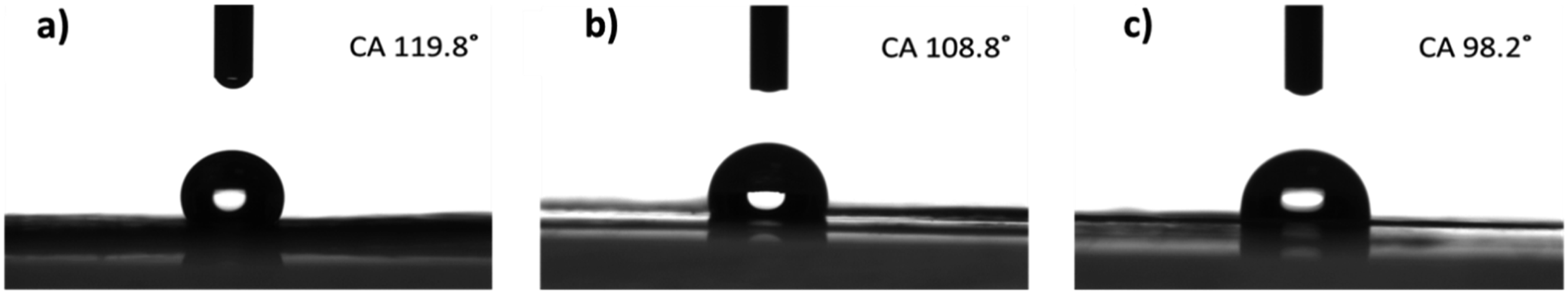
XRD results of untreated and sized CFs are summarized in Figure 7. As observable, the characteristic peak for CF itself occurs around 25°.
50
Remarkably, the intensity increases through the sizing due to the binding of the CF’s surface with sizing agents. Remarkably, the crystal system of the neat CF’s is monoclinic with a dominant peak for the miller indices (020) and a d-spacing of 15 Å, while the sized samples exhibit a cubic crystal system with a dominant peak for the indices (022) and a d-spacing of 10 Å. The average crystallite size was found to be 66 ± 14 Å for neat CF, 34 ± 7 Å for PEI-coated CF and 75 ± 15 Å for the PEI-PEEK blend coated CF. Thus, PEI decreases the average crystallite size (CS) whereas the addition of PEEK to the coating material increases the average CS. Furthermore, crystalline peaks are getting sharper which indicates an increase in crystallinity during the sizing process. The mechanism for these changes in the crystallographic properties might be related to the fact that PEI is an amorphous polymer whereas PEEK is semi-crystalline. Moreover, the presence of the thermoplastic polymer layer can introduce stress and strain on the carbon fiber surface during processing, which may affect the arrangement of carbon atoms and consequently the crystal structure. Remarkably, changes in the crystallinity of sizing materials are correlated with wettability results of treated and untreated CFs. Since the PEEK based sizing agent has the highest crystallinity the smallest CA (98.2°) belongs to PEEK-sized CFs because crystalline regions often have distinct surface areas compared to amorphous regions. This variation in surface area can impact the overall surface energy by altering available sites for interaction. Thus, higher surface area, associated with increased crystallinity, can lead to a higher surface energy due to enhanced interactions with surrounding molecules.51,52 Hence, adhesion between fiber and matrix is improved when the crystallinity is enhanced. XRD results of neat CF (a), PEI sized CF (b) and PEI-PEEK blend sizing for CF (c).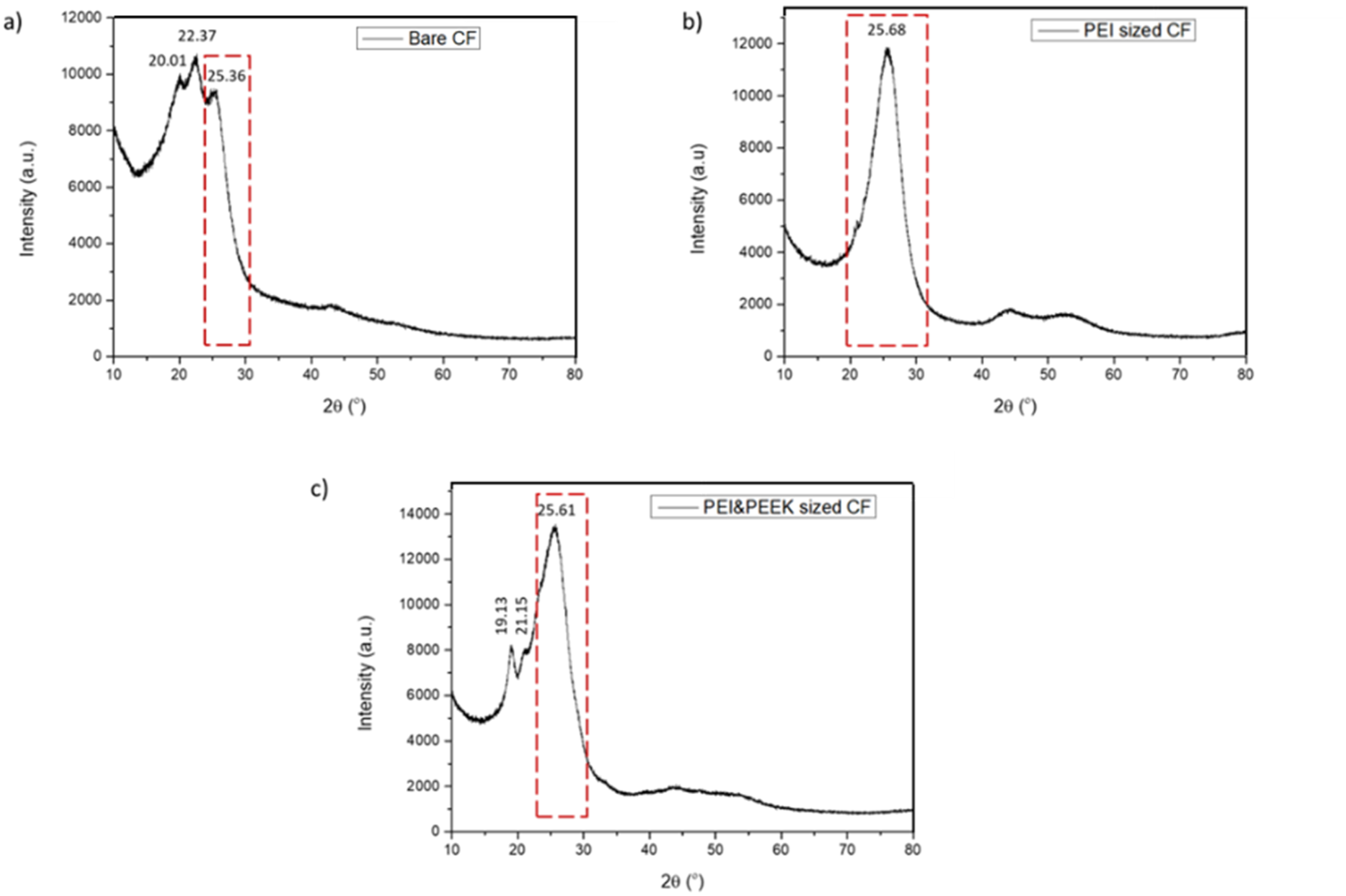
Thermal Analyses of Sizing Polymers
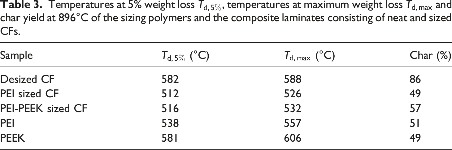
Thermal degradation tests were carried out in order to analyze the thermal stability of sized specimens. Corresponding results and affiliated derivative thermogravimetric (DTG) curves are presented in Figure 8 in combination with Table 3 where also results for the PEI and PEEK polymers are included. During the decomposition process of PEI the main chain breaks up quite quickly. At 600°C, PEI is decomposed and removed as volatiles.53,54 In addition, PEEK decomposition is initiated below 600°C by ether chain scission with major volatile products as phenols, 4-phenoxyphenol, 1,4-diphenoxybenzene, carbon monoxide and carbon dioxide in the first decomposition step.55–58 Second steps are observable due to oxidation of the formed carbonaceous char. Moreover, above 550°C oxidation of CFs occurs.50,59,60 Thus, results indicate that the PEI-PEEK blend presents increased thermal stability in comparison to the PEI polymer as summarized in Table 3. Note that observable variations in the char amount of the PEEK polymer and PEI-PEEK sized CF laminates in contrast to the PEI and PEI sized CF laminate occur due to variations in the sizing amount. Note that Figure 3(e) reveals average sizing thicknesses of 0.6 μm, however, values between 0.5 and 0.8 μm corresponding to sizing volume variations of up to 36 % are observable. (a) TGA and (b) DTG curves for the sizing polymers (i.e. PEI, PEEK) and the composite laminates consisting of neat, PEI sized, and PEI-PEEK sized CFs. Temperatures at 5% weight loss 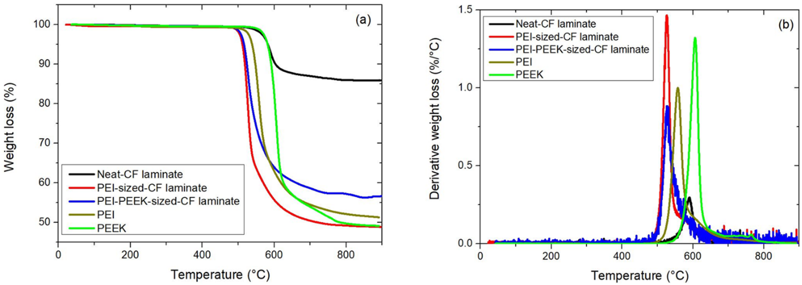
Mechanical Results of CFRTP Composites
Effects of sizing on mechanical properties of CF reinforced thermoplastic composites were analyzed by applying tensile tests onto laminates. Hence, Young’s modulus and the tensile toughness of the composites were determined. Results are summarized in Figure 9 and Table 4. Mean tensile stress-strain curves for laminates made up of neat CF, PEI sized and PEI-PEEK sized CF. Tensile test results of laminates manufactured with desized and sized CFs in combination with PEEK as matrix.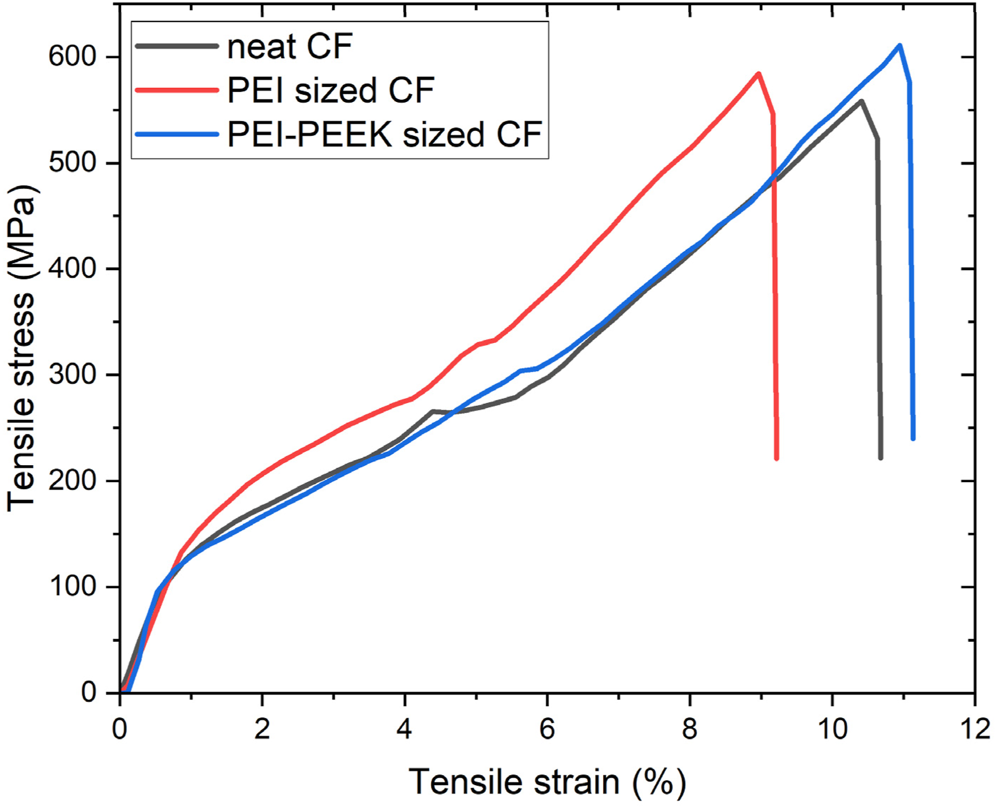
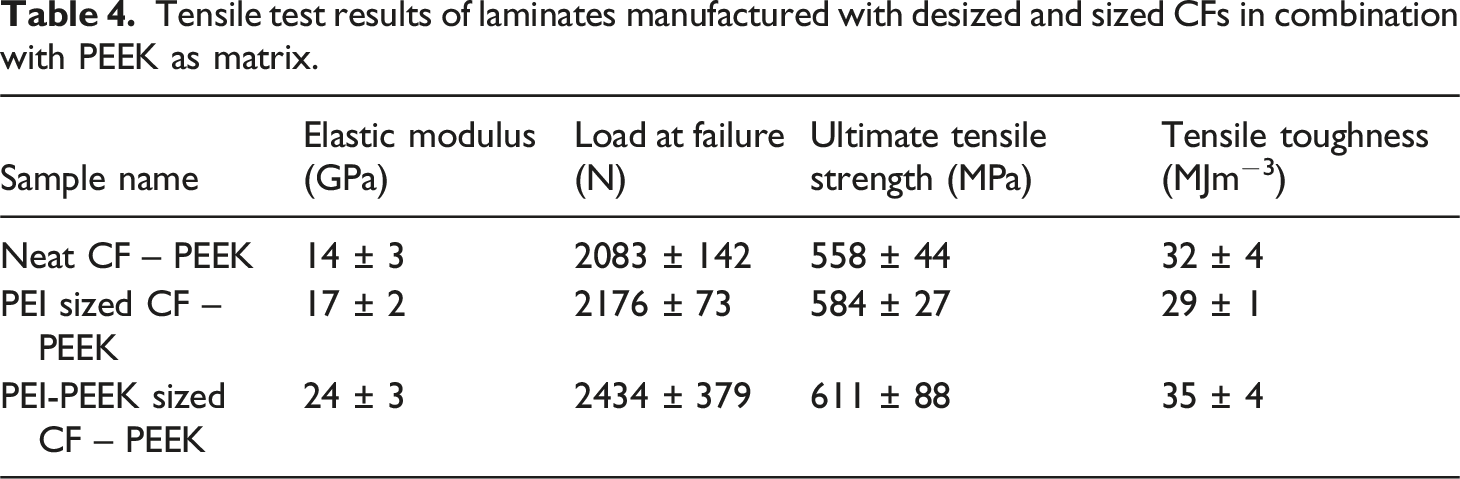
Figure 9 indicates that extension rate and tensile stress of laminates were increased after sizing as a result of enhanced fiber-matrix interactions. Corresponding mean and standard deviation values are presented in Table 4. Remarkably, results for the elastic modulus, i.e. slopes of the curves in Figure 9, are in agreement with results of comparable CF reinforced PEEK composites reported in the literature.61,62 Interestingly, the interaction between sizing and matrix could lead to changes in the local stiffness of the matrix material near the fibers. As a result, the elastic modulus might differ from what the rule of mixtures predicts. Note that a one-way analysis of variance (ANOVA) was performed in order to confirm that the differences in the mechanical results are significant. The probability value, i.e. p-value, lies at 0.01125, 0.04004, 0.04314 and 0.01252 for the elastic modulus, load at failure, ultimate tensile strength and tensile toughness, respectively. Thus, it lies lower than the significance level of 0.05 for all properties. Hence, the null hypothesis can be rejected which indicates that the results are of relevance.
Mechanical properties were enhanced as a result of increased interfacial bonding throughout the sizing application. It can be observed that the average tensile toughness increased from 26 MJm−3 to 32 MJm−3 by PEI sizing while 35 MJm−3 was obtained after the PEI-PEEK blend sizing in agreement with the literature. 63 Note that tensile test results are correlated with wettability results. As the CA of neat CF decreases through PEI and PEI-PEEK sized CFs, fiber-matrix interaction increased by the process application. Thus, mechanical properties of CF reinforced thermoplastic composites are enhanced by the approach.
Conclusion
In this study, polymeric sizing materials, which are compatible with the surface of CF and thus do not lead to any separation between fiber and coating material, were focused on. Chemical compatibility between reinforcement material and matrix led to strong adhesion. Hence, nitrogen bridges through the fiber surface facilitate adhesion of CFs with the TP matrix since the CA of neat CF was 119.8° while it decreased to 108.8° for PEI sized CF and to 98.2° for PEI-PEEK sized CF. As a result, the adhesion property of CF was enhanced. Optimum wettability was achieved through sizing of CFs by blending PEEK with PEI that led to the highest mechanical strength for final composites which show improved tensile properties. For instance, the tensile toughness was increased by 26 % by sizing of neat CF through the PEI-PEEK blend.
Remarkably, presented results are open to further improvements with respect to industrial applications. The next step would be the spooling of modified CF bobbins in such a way that fiber bundles can be twined in unidirectional (UD) form which in turn could be used in the manufacturing of CFRTP based aerostructures.
Footnotes
Acknowledgements
Authors are grateful to the Institute of Materials Science and Nanotechnology at Bilkent University and Turkish Aerospace for support. Authors also thank S. Toros for valuable discussions.
Declaration of conflicting interests
The author(s) declared no potential conflicts of interest with respect to the research, authorship, and/or publication of this article.
Funding
The author(s) disclosed receipt of the following financial support for the research, authorship, and/or publication of this article: This work was supported by the Scientific and Technological Research Council of Turkey within the programs 1515 and 1004 with project numbers 5189901 and 20AG001, respectively.