
Abstract
Gaps and void pockets are inevitably present in tailored thermoplastic composite preforms manufactured via automated fiber placement (AFP). Filling these gaps and voids can be challenging during the consolidation due to the high viscosity of thermoplastic composites, especially in the case of vacuum-bag-only (VBO) consolidation, where the applied pressure is limited. Therefore, the current work investigates whether one bar pressure is sufficient to fill the gaps and voids during VBO consolidation. For this purpose, two experiments are performed. First, a hot plate setup is built and used to capture the real-time gap-filling behavior during the VBO consolidation. Second, VBO consolidation of tailored preforms is performed to study the filling of ply-drop induced void pockets. Here, the tailored preform consists of plies of different orientations dropped at different locations to verify if one bar pressure available during the VBO process is sufficient to fill the void pockets. The results from both experiments answered the main question that one bar pressure is sufficient for filling the gaps and void pockets for the given material systems, and further, it was confirmed that the transverse squeeze flow was dominant in filling gaps. However, in the case of fillings of ply-drop induced void pockets, the orientation of the dropped ply and covering plies majorly dictated the filling behavior.
Introduction
Cost-effective manufacturing of large and complex aerostructures, such as wings, fuselage sections or spars, is not straightforward for thermoplastic composites. The two obvious manufacturing technologies for such structures are autoclave consolidation (AC) and in situ automated fiber placement (AFP). However, the former seems expensive in terms of tooling and operational costs, while the latter still lacks technological maturity and probably will not see commercial application within the coming decade(s).1–4 Therefore, the industry is currently banking on a two-step approach involving the automated deposition of high-quality tape using AFP, followed by an out-of-autoclave consolidation process, such as, for example, vacuum-bag-only (VBO) consolidation, to enhance the consolidation quality of the part to meet the aerospace standards.5–7
In the case of thermoplastic composites, the knowledge on the use of low-pressure consolidation processes, such as VBO consolidation is minimal. The studies on VBO processing of flat (uniform thickness) thermoplastic composite laminates highlighted that evacuation of entrapped air or volatiles from the composite stack prior to consolidation is crucial in achieving void-free consolidation.8–11 The two physical phenomena responsible for void removal are i. void reduction by dissolution and diffusion and ii. in-plane air evacuation, the details of which are discussed elsewhere.12,13
Swamy et al.14,15 studied two-step AFP and VBO consolidation of C/PEKK thermoplastic composites. They presented the idea of engineering the in-plane air evacuation channels in the preforms by deliberately creating gaps between the tapes during the placement. In the case of thick laminates, where the time needed for void reduction by means of through-thickness diffusion is too long, the entrapped air and volatiles from the preform can diffuse to these channels and evacuate to the perimeter of the part prior to consolidation. Figure 1 presents a schematical illustration of a preform with well-defined gaps that can be used as in-plane air channels. Schematical illustration of a fiber placed perform with well-defined gaps used as in-plane air channels (dotted lines) during the consolidation process.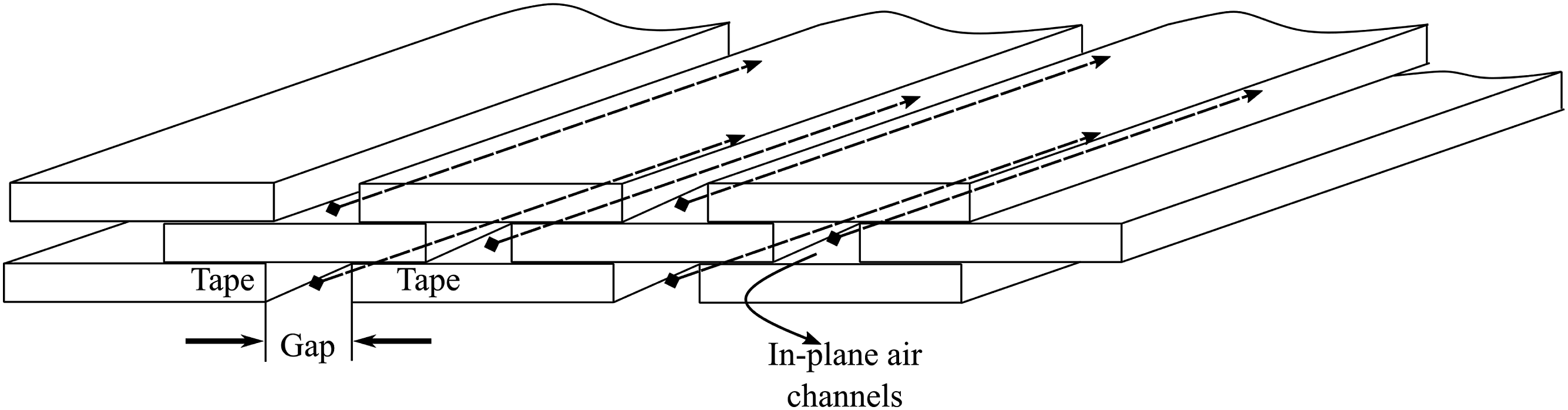
After, or simultaneously to, the air evacuation process, the gaps that assisted in the evacuation process must be filled to achieve void-free consolidation. 13 In order to fill the gaps, the tape material is transversely squeezed to flow into the gaps. However, the maximum available pressure during the VBO consolidation process is limited to one bar. Therefore, it is essential to know if this one-bar pressure is sufficient to fill these gaps. Further, identifying the temperature at which the gaps start to fill can assist in optimizing process parameters for effective air evacuation via in-plane air channels.
Studies on the two-step AFP and VBO consolidation of thermoplastic composites is majorly limited to flat laminates with a uniform thickness. However, in practical applications, flat laminates are seldom used. Instead, it is common to use tailored sections where the plies are dropped at specific locations to optimize the structure’s mechanical performance.
16
Peeters et al.
17
studied ply drops in thermoplastic composite materials manufactured using laser-assisted tape placement and stated that the ply drop zones in the preforms generally lead to void pockets. Figure 2 presents a microscopic cross-section of a typical ply-drop induced void pocket in a fiber-placed preform. Microscopic cross-section of a fiber placed ply dropped section.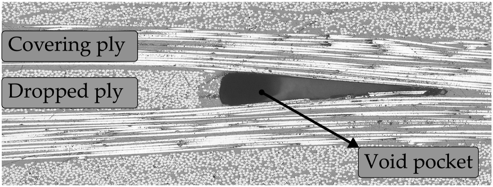
During the VBO consolidation of flat, uniform-thickness thermoplastic composite laminates, the main focus is on gas evacuation. However, in the case of tailored, non-uniform thickness parts, filling of void pockets is also vital in achieving a good consolidation. The two main material flow mechanisms expected here are the transverse squeeze flow of tapes (affine flow) and the bleeding of the matrix material from tapes (percolation flow) into the void pockets.18–20 However, the fundamental question remains if one bar pressure during the VBO process can facilitate the necessary flow to fill voids in tailored structures. If yes, what type of flow is dominant?
Objective and approach
The main objective of this work is to determine if the one-bar pressure available during the VBO consolidation is sufficient to fill gaps and voids present in the fiber-placed preforms. Therefore, two sets of experiments are designed. The first experiment involves the real-time observation of the filling of gaps during the VBO process. For this purpose, a unidirectional (UD) preform with a gap of 1 mm between the tapes is VBO consolidated in a customized hot-plate setup featuring a glass window. The setup assists in monitoring and capturing the real-time filling of gaps. During the experiment, images were taken at every 30 s, and later the images were processed to track the gap-filling behavior.
The second experiment is the two-step AFP and VBO consolidation of tailored performs. First, the tailored preforms with non-uniform thickness were laid down at high speeds (200 mm/s) using AFP. Later, the preforms were VBO consolidated, and cross-sectional micrographic images were extracted from AFP-laid preforms and VBO consolidated laminates to judge the filling of void pockets. The results from the experiments will not only answer the question if one bar pressure is sufficient to fill the gaps and void pockets but can also help in identifying the dominant flow mechanisms, which, in the future, will be beneficial in the development of processing guidelines for VBO consolidation of large and complex fiber-placed thermoplastic structures.
Experimental work
Materials
UD C/PEKK slit tape of width 6.35 mm from two different suppliers is used: APC (Solvay) and Cetex
Ⓡ
TC1320 (Toray Advanced Composites). Figure 3(a) and (b) provide cross-sectional micrographs of APC and TC1320 tape, respectively. The tapes consist of AS4D fibers with a fiber volume fraction of around 60 %, and the melting (Tm) and processing temperature (Tp) are around 343°C and 375°C, respectively. Although the tapes appear to be very similar on datasheets, the tape morphology, such as surface roughness and fiber-matrix distribution is different, which can be observed in Figure 3. Cross-sectional micrographs of as-received C/PEKK tapes from two different suppliers, (a) APC tape with a rough surface and uneven fiber-matrix distribution (b) TC1320 tape with a smooth surface and even fiber-matrix distribution.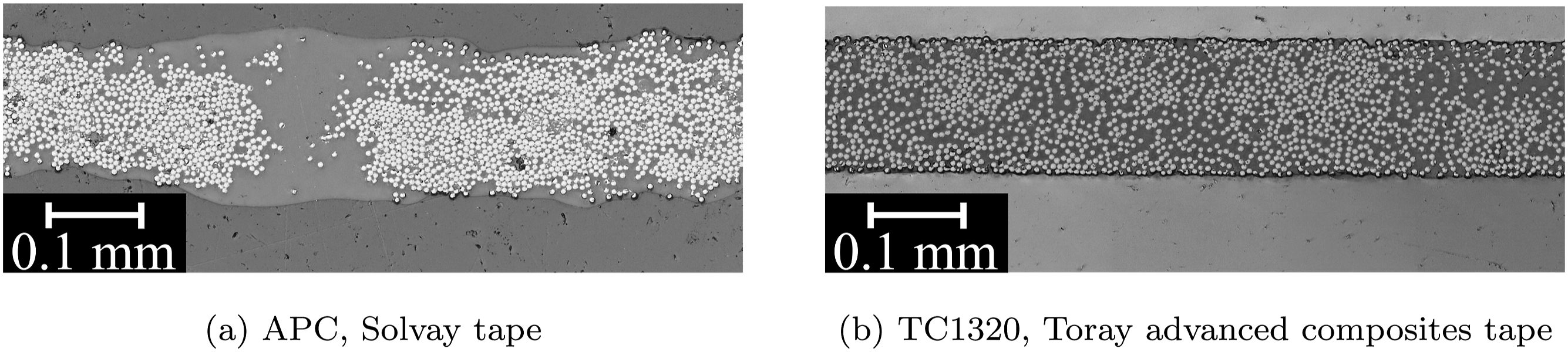
Real-time observation of gap filling
Sample preparation
A Coriolis Composites fiber placement robot was used for sample preparation. The robot placed the 6.35 mm wide tapes next to each other on a non-heated mold surface with an intended gap of 1 mm between the tapes. Around 40 tapes were placed to reach an in-plane dimension of 300 mm × 300 mm. During the placement, A 1 kW diode laser with a spot size of 28 mm in height and 11 mm in width at a laser angle of 17° served as a heat source to achieve a nip point temperature of 360°C–380°C. A deformable compaction roller of 60 shores hardness applied a force of 750 N. Three layers of tapes were placed on top of each other to have a sufficient thickness to capture the transverse squeeze flow of tapes during the experiments. Figures 4(a) and (b) schematically illustrate the samples’ top and cross-section view, respectively. A schematic illustration of the samples used for real-time observation of filling of gaps during the VBO process. (a) Top view of tapes with gaps. (b) Cross-sectional view tapes with the gap.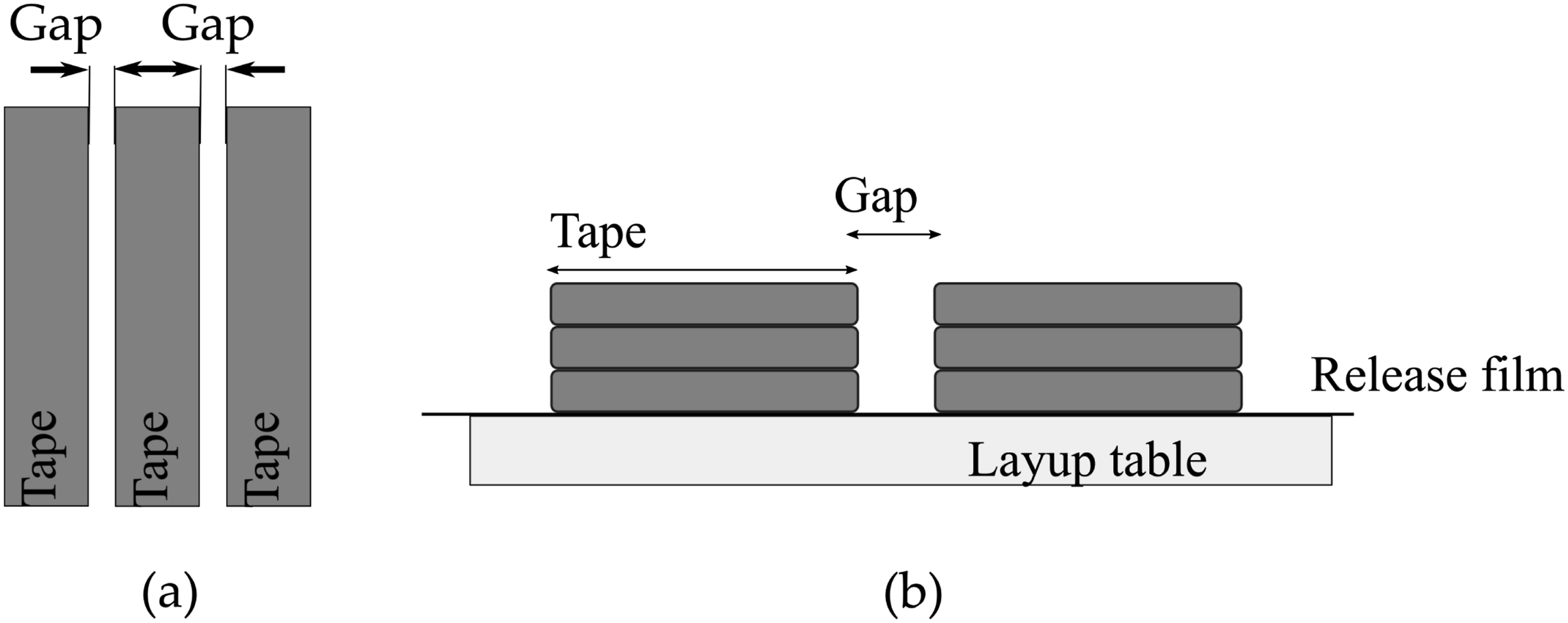
Experimental setup
The setup used for this work is a hotplate designed for VBO consolidation of thermoplastic composites and is similar to the setup used by Krämer et al.
21
for observing waviness formation during the VBO consolidation of thermoplastic composites. Figure 5 is a graphical representation of the setup used. It consists of a 400 mm × 400 mm brass hotplate equipped with heating elements and cooling channels that assist in temperature control. An aluminum plate coated with the Marbocote 227CEE release agent was placed on top of the hotplate, which acted as a thermal diffuser. The samples prepared were placed on the aluminum plate with a release film UPILEX® 25S between the sample and the aluminum plate. A vacuum bag is placed on top, and a square portion is cut out of the bag where a glass plate coated with a release agent was placed to create a window of 100 mm × 100 mm for observation. Finally, the sealant tape was used to seal the bag, and a vacuum pump was used to maintain a pressure of less than 0.1 bar in the setup. An IDS uEye UI549xSE-M camera was placed on top to record the filling of the gaps during processing. Schematic illustration of the vacuum-assisted hotplate with a glass plate on top, where. 1 = camera, 2 = tacky tape, 3 = glass plate (200 mm × 200 mm), 4 = glass-wool breather, 5 = thermocouple (K type), 6 = aluminum heat diffuser with vacuum channels (350 mm × 350 mm), 7 = cooling channels, 8 = hot plate (400 mm × 400 mm), 9 = heating cartridges, 10 = vacuum channel, 11 = edge dams, 12 = gap between tapes to be filled, 13 = tapes, 14 = vacuum bag.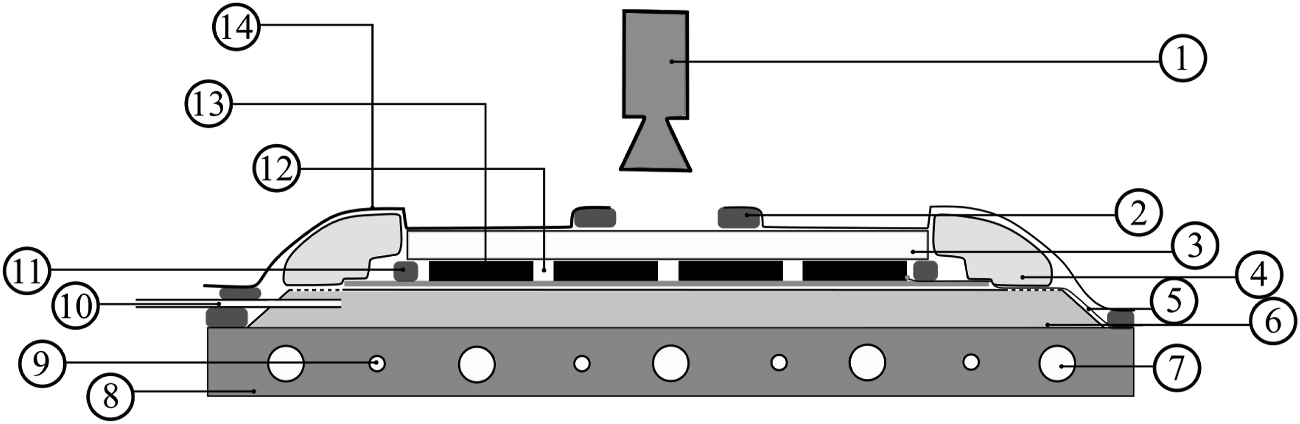
Experimental procedure
Once the setup is ready, the vacuum is applied, and the samples were heated to a temperature of 375°C and cooled down to room temperature at the rate of approximately 4°C/min with a dwell of 30 min at 375°C.
Image analysis technique
During the hotplate experiments, images were taken every 30 s. Later, the images were processed to evaluate the gap closure with respect to the processing temperature. Figure 6 presents the approach used for tracking the gaps. First, the snapshots were taken during the process, as seen in the left image in Figure 6. Next, a rectangular section of 500 pixels by 200 pixels involving the gap is selected and cropped, as seen in the middle image in Figure 6. Then the cropped sections were iteratively thresholded and binarized, as in the right image in Figure 6. Finally, the gap sizes were tracked based on the white pixels and averaged over the length of the image. This exercise was performed for both the material systems, and three locations were chosen to track the gap size for each material system. Approach for tracking the gap filling during the hotplate experiment.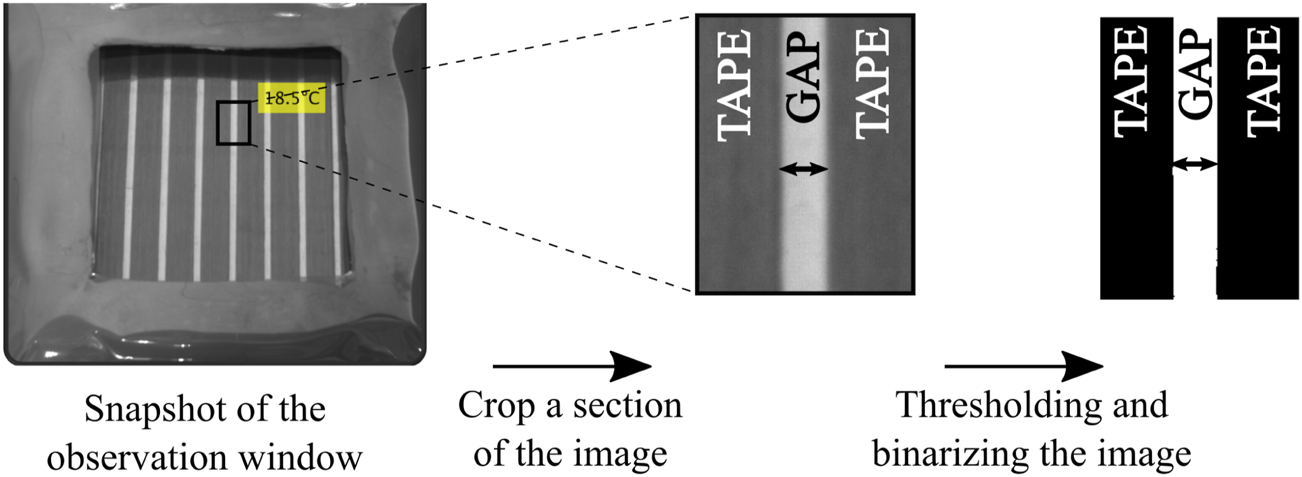
Vacuum-bag-only consolidation of tailored fiber-placed preforms
Layup configuration
A 12-ply quasi-isotropic layup configuration was chosen. Plies of different orientation angles were dropped at different planar locations. Figure 7(a) presents a schematical illustration of the top view of the fiber-placed preform. This illustration highlights the dropped plies, covering plies, and, more importantly, the edges of the dropped plies. Due to the fixed angle tape cutting setup, the edges of the −45 or 45° ply are not straight but a staircase (saw-tooth) like edge. Further, this Figure indicates the location of samples taken for microscopic inspection to analyze the quality. Figure 7(b) shows a schematic illustration of the cross-sectional view of the layup with the details of ply dimension, orientation, and the location of the dropped plies. Though the layup is not close to real-life examples, this layup enables to drop plies in all major orientations. Schematic illustration of (a) the top view of layup configuration indicating the location of samples taken for microscopic inspection (b) the cross-sectional view of layup configuration indicating the dropped plies planar location and orientation.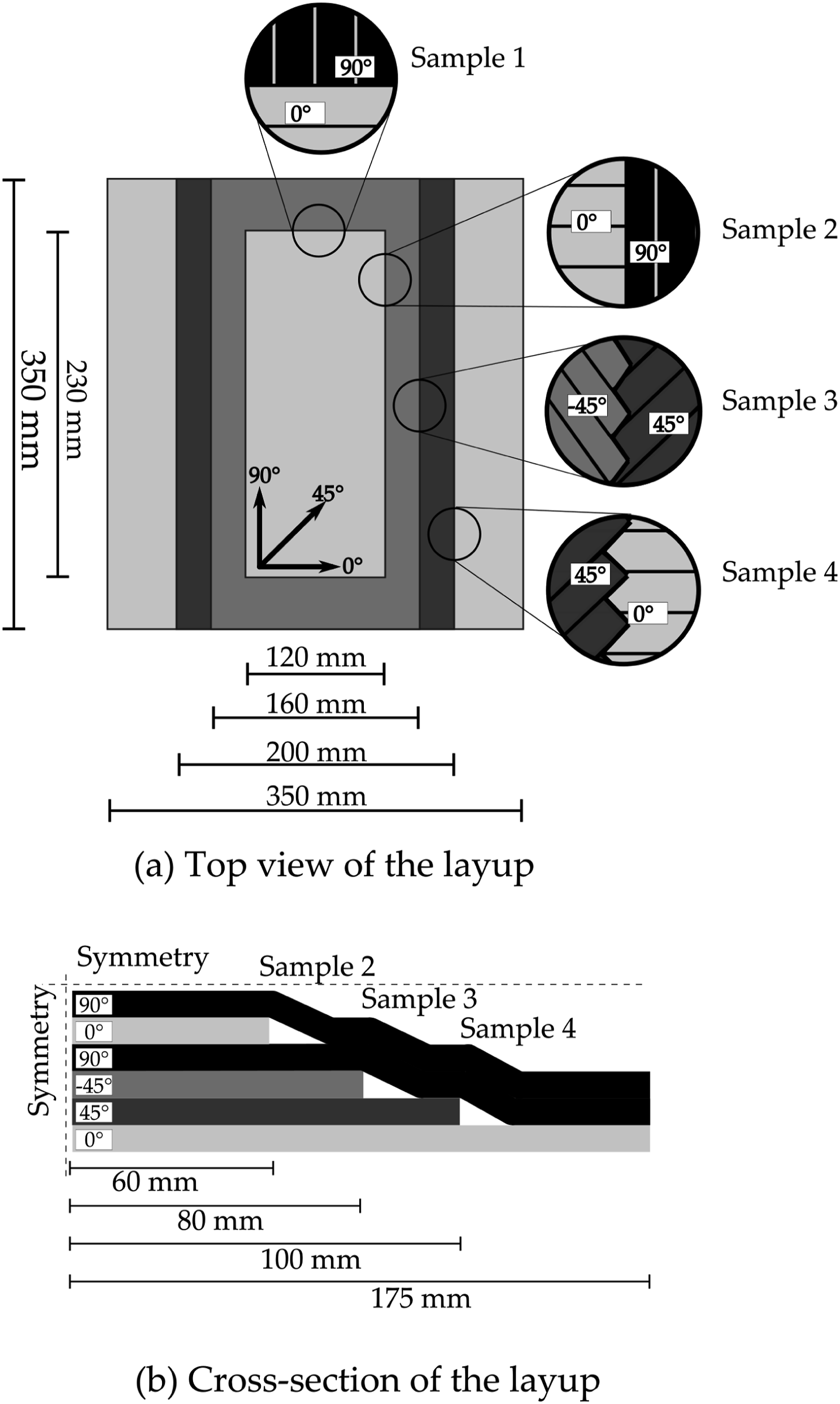
The layup procedure was similar to the one defined in section sample preparation. All preforms were laid down using a Coriolis Composites’ fiber placement robot with 6.35 mm wide tapes without gaps on a non-heated mold surface at 200 mm/s speed. During the layup, a nip point temperature of 360 °C–380°C and a compaction force of 750 N were maintained.
Vacuum-bag-only consolidation
The preforms were consolidated using a VBO setup. Figure 8 schematically illustrates the VBO setup used. It consists of a 600 mm × 600 mm steel base plate. The preform was placed on the mold, and porous release films UPILEX® 25S of thickness 25 μm were used on both the top and bottom of the preform. Glass wool breather was placed around the preform, and on the top, eight plies of woven glass fabric were used to enable better air evacuation. Finally, 50 μm polyimide film was used as a vacuum bag and is sealed off using a high-temperature A-800-3G, AIRTECH sealant tape. Schematic illustration of the vacuum bag set-up used for the VBO consolidation.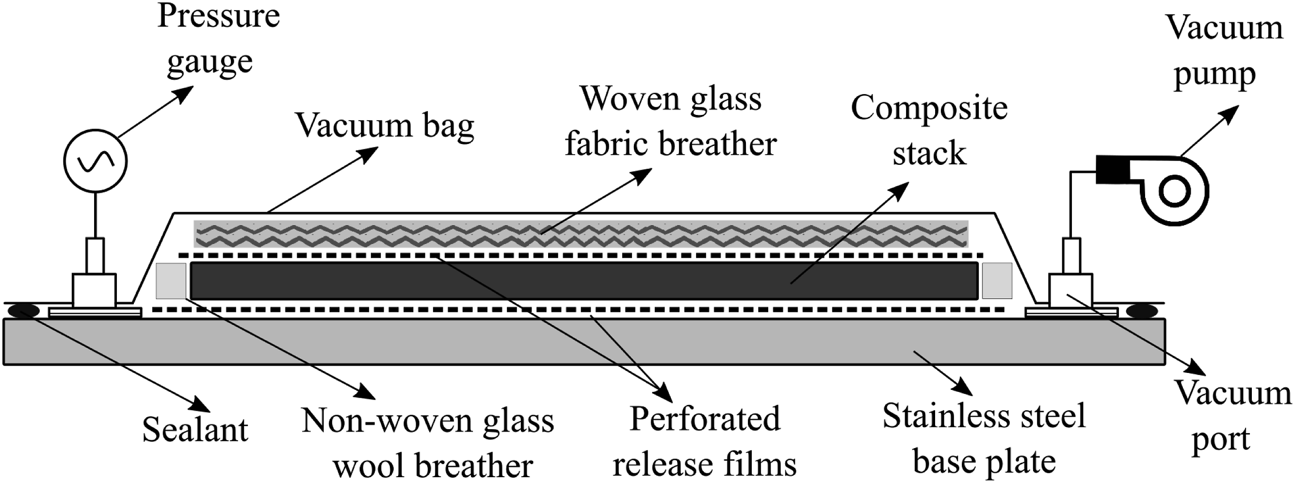
The processing was performed in a convection oven, by heating the VBO setup up to 375 ± 5°C at the rate of 4°C/min, followed by a dwell for 30 min, after which the setup was cooled down to room temp at a rate of 4°C/min.
Consolidation quality
The consolidation quality was mainly judged based on the microscopic cross-sectional images. A Keyence VHX-5000 with 300x magnification is used to obtain high-resolution and high-contrast images of the samples. Microscopic samples were extracted from the location as shown in Figure 7(a) both from preforms and VBO consolidated part.
Results and discussion
Real-time observation of gap filling
Figures 9 and 10 are the snapshots captured during the gap-filling process at various temperatures for APC and TC1320, respectively. Figure 9 presents the filling behavior in the APC material system. It is observed that at 162°C, just above the Tg, there were wet patches on the glass plate, which remained unchanged until the melting temperature of the polymer was reached. These wet patches can be attributed to the softening of the excess resin on the surface of the APC tapes. The presence of excess resin on the top and bottom surface of APC tapes can be confirmed by the cross-sectional micrograph in Figure 3(a). In the snapshot at 337°C, which is just after the melt temperature of the tape, the gaps were partially filled, and by 358°C, the gaps were completely filled. Snapshots of gap filling at various temperatures during the VBO processing of APC material. Snapshots of gap filling at various temperatures during the VBO processing of TC1320 material.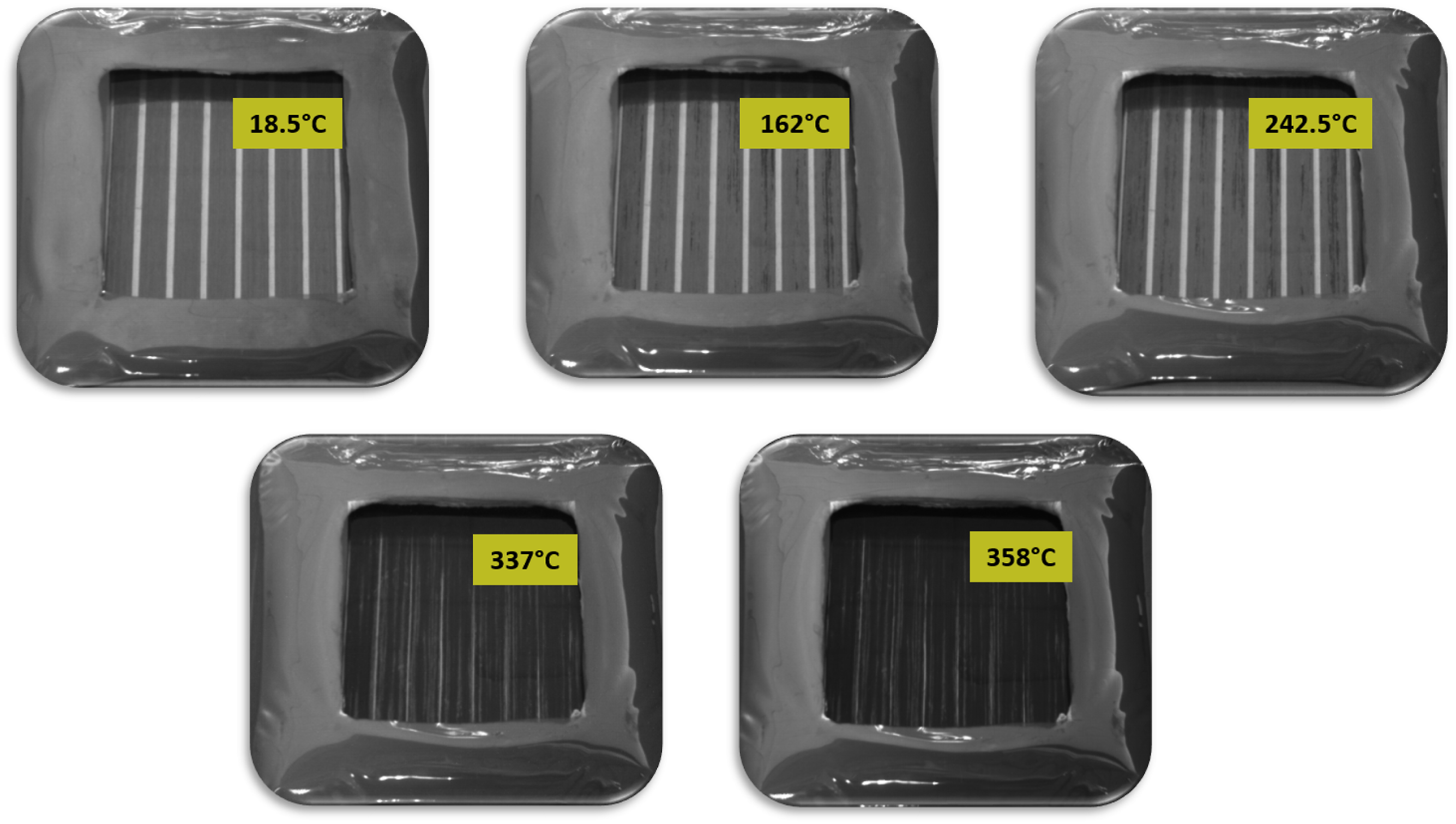
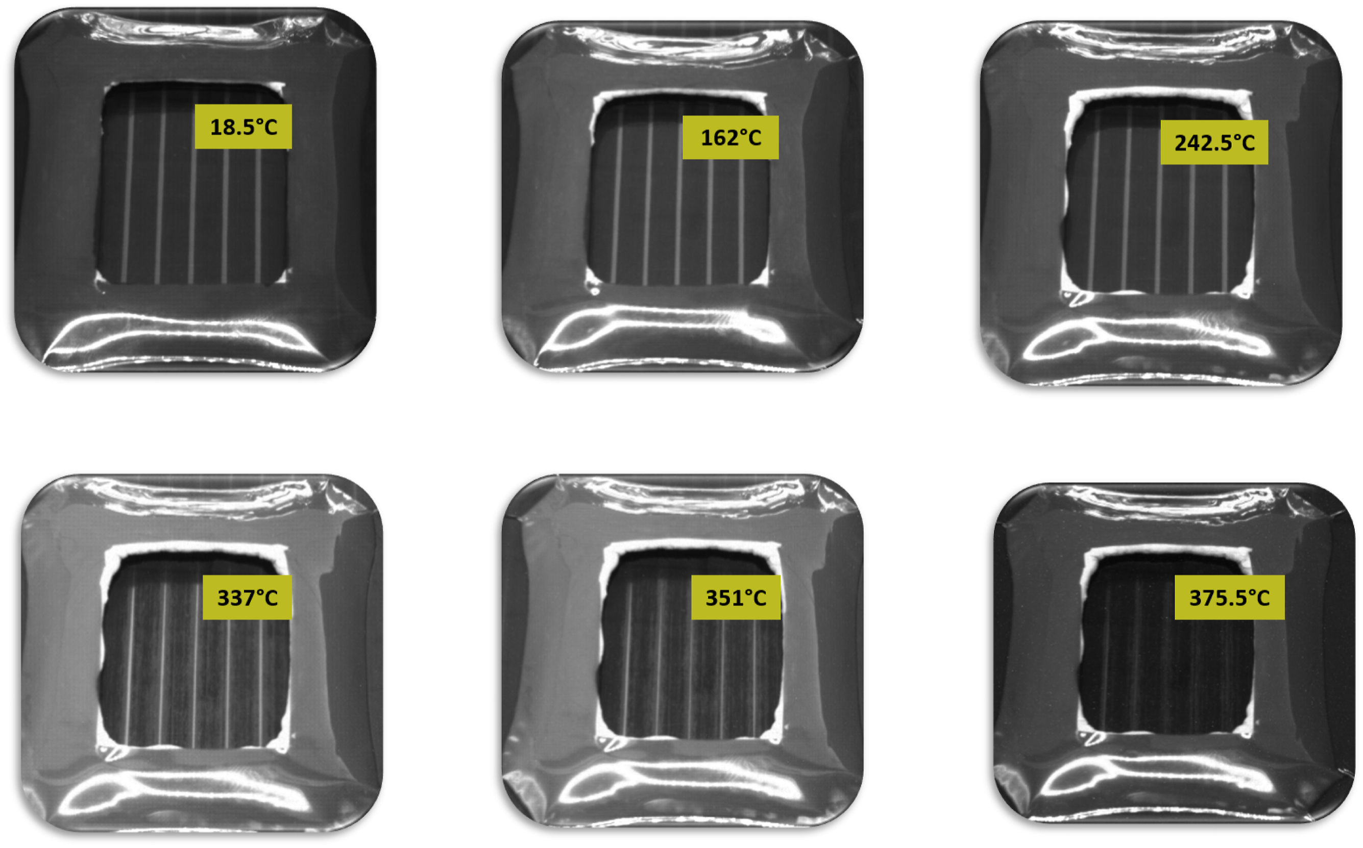
In the case of TC1320, it can be observed from Figure 10 that there is no change in the gaps until 242°C. In the snapshot at 337°C, which is just after the melt temperature of the tape, the gaps were partially filled, while they were entirely filled at 375°C. The time needed for the complete closure of gaps was longer for TC1320 than for APC.
Figure 11 presents the results of the continuous tracking of gap sizes with respect to the processing temperature for both APC and TC1320 material systems. Three locations were tracked for both material systems. The graphs were smoothed with a moving average filter to reduce the noise from the data set. Note that the initial gap sizes are not the same for both material systems, as placing the tape with the precise gap sizes was challenging. Real-time tracking of gap filling during VBO processing of both APC and TC1320 material system.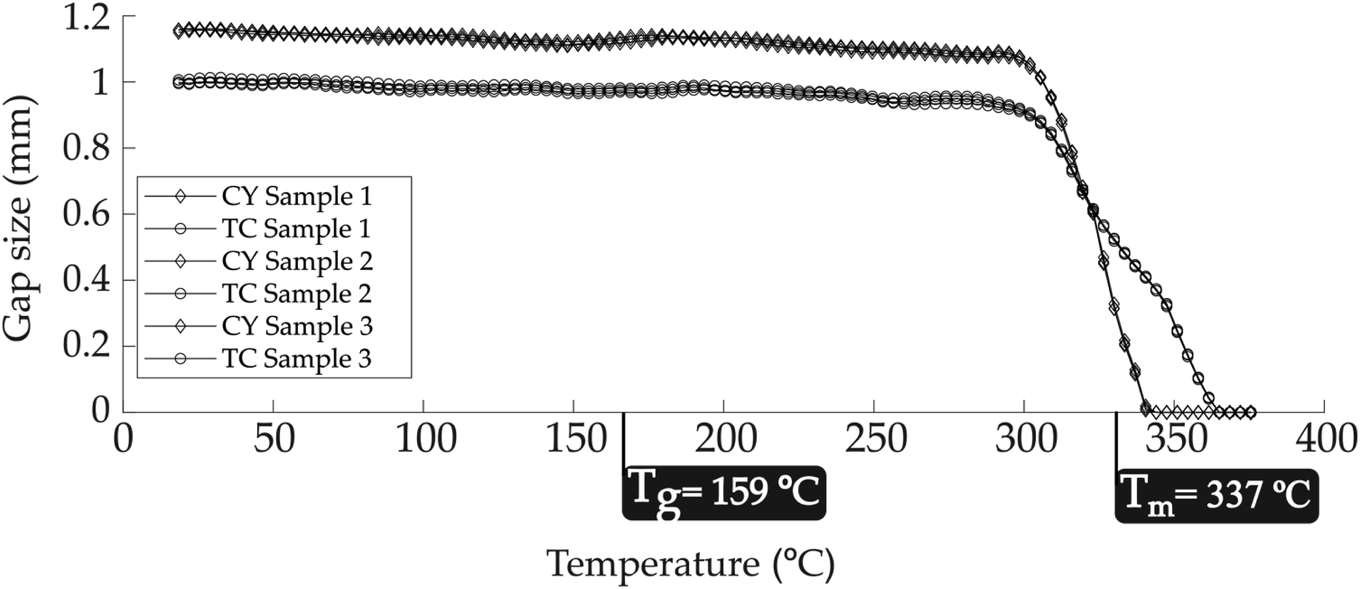
It is seen from the graph that at around 300°C, which is just below the reported melting temperature of C/PEKK tapes, the gaps start to close in both cases. However, in the case of APC, the gaps closed faster than TC1320 and were filled when a temperature of 350°C was reached. On the contrary, in the case of TC1320, the gap-filling process was longer and was finished at 375°C.
Time for filling of gaps
The fibers in the tapes were oriented parallel to the gaps, which meant that transverse squeeze flow was the main flow responsible for filling gaps. Figures 12 and 13 are the microscopic cross-sections of three layers of tapes with a gap of 1 mm consolidated via the hotplate setup of APC and TC1320 tape material, respectively. The micrographs indicated that the gaps were completely filled. Further, it was hard to identify the exact location of the gaps in the micrographs as the flow was dominantly a transverse squeeze and showed no change in the fiber-matrix distribution after filling. Cross-sectional micrograph of APC tapes after gap filling. Cross-sectional micrograph of TC1320 tapes after gap filling.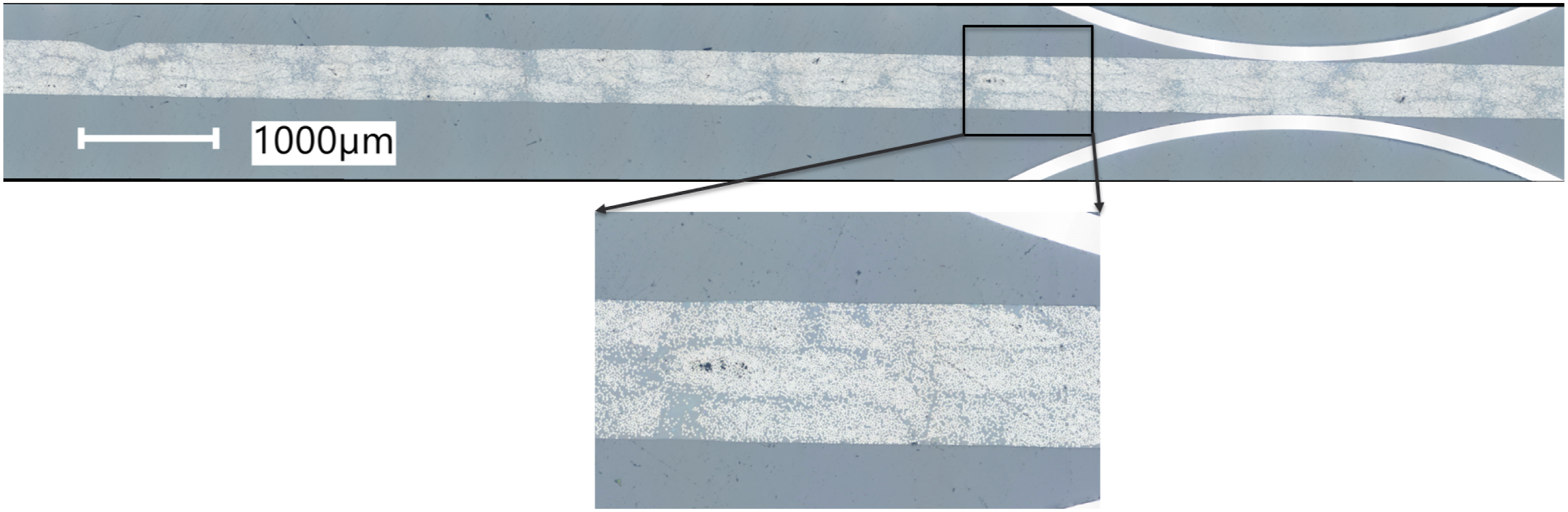
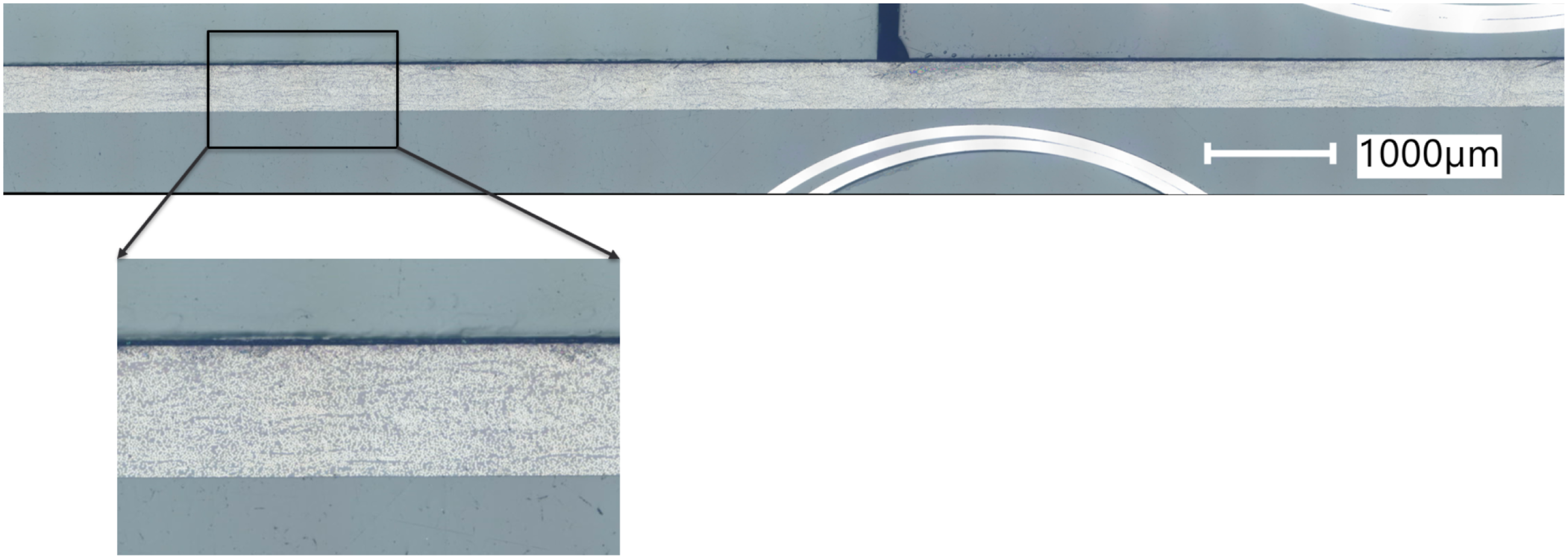
Figure 14 provides the schematic illustration of gap filling by a transverse squeeze of tapes. The experimental results showed that one bar pressure is sufficient for the material flow to fill the gaps. However, in the experiments, three plies of tape were stacked to facilitate easy flow and observation of the gap filling. In reality, there is usually one ply, which has to squeeze to fill in the gaps. Schematic illustration of gap filling by a transverse squeeze of tapes.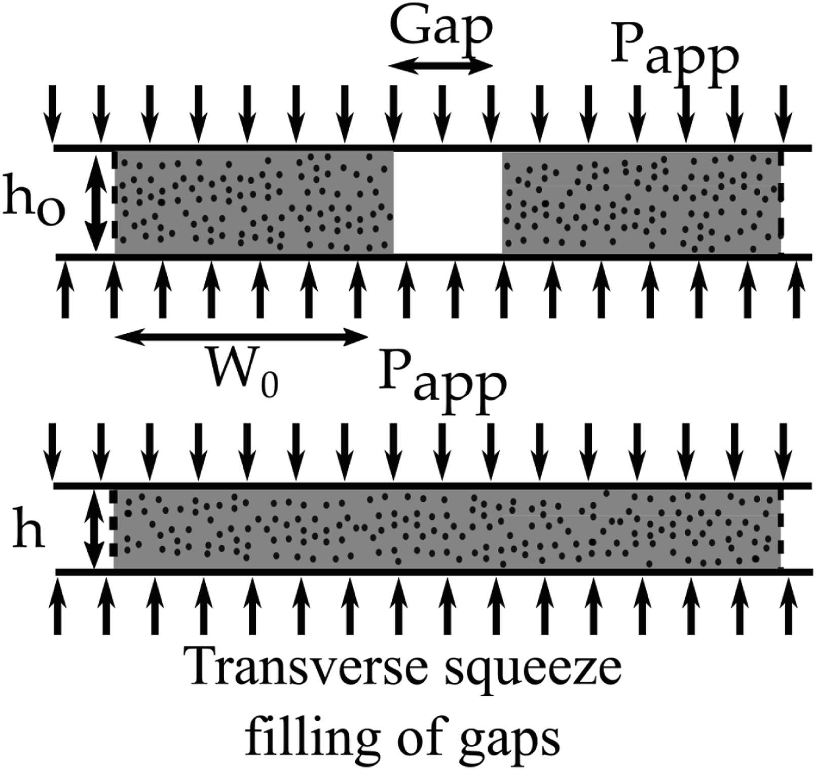
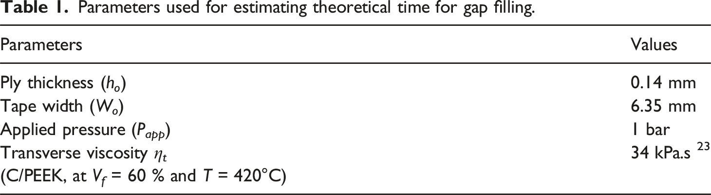
Theoretical squeeze flow models can be used to estimate the time required to fill the gaps. Roger’s model is widely used where the time for filling the gaps depends on the width of the gap, the ply thickness, the transverse viscosity of the tape material, and pressure applied in 22. Slange et al. 3 Estimated the void filling time during the stamp forming process. The same methodology is used to calculate gap-filling times during VBO processing. For the theoretical time calculation, one ply thickness is considered rather than 3 plies as in experiments.
The time required for transverse squeeze filling tsqueeze can be calculated based on the equation,
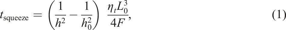
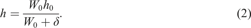
where h0 is the initial height of a tape, ηt is the transverse squeeze viscosity of the tape material, F is the applied force which equals W0Papp, Papp is applied pressure, and h is the final reduced height of the ply after the filling of gaps and can be calculated by volume conservation based on the geometry of the gap to be filled. In the case of gap-filling experiments, the final height of the ply can be calculated by,
Parameters used for estimating theoretical time for gap filling.
Filling of the wide gaps may cause local thickness variation, and it is essential to understand that the variation in the local thickness can play an important role in terms of mechanical performance.
Vacuum-bag-only consolidation of tailored fiber-placed preforms
The current section presents the micrographic analysis of void filling during the VBO consolidation of tailored preforms. Figure 15 presents the results of the APC material. The left column of Figure 15 presents the micrographs of the fiber-placed preforms. Figure 15(a), (c), (e) and (g) correspond to samples 1, 2, 3, and 4, respectively, as presented in Figure 7. As the preforms were laid down at 200 mm/sec speeds, there was little time for filling the void pockets. Further, some intra-tape voids are seen, typical for fiber-placed preforms. The right column of Figure 15 presents the micrographs of VBO consolidated fiber placed performs. Figures 15(b), (d), (f), and (h) correspond to samples 1, 2, 3, and 4 after VBO consolidation. It is very clear from the micrographs that the quality of consolidation visibly increased, and the void pockets were filled with no intra-tape voids. Cross-sectional micrographs APC non-uniform thickness preform on the (left column) and VBO consolidated APC non-uniform sections on the (right column).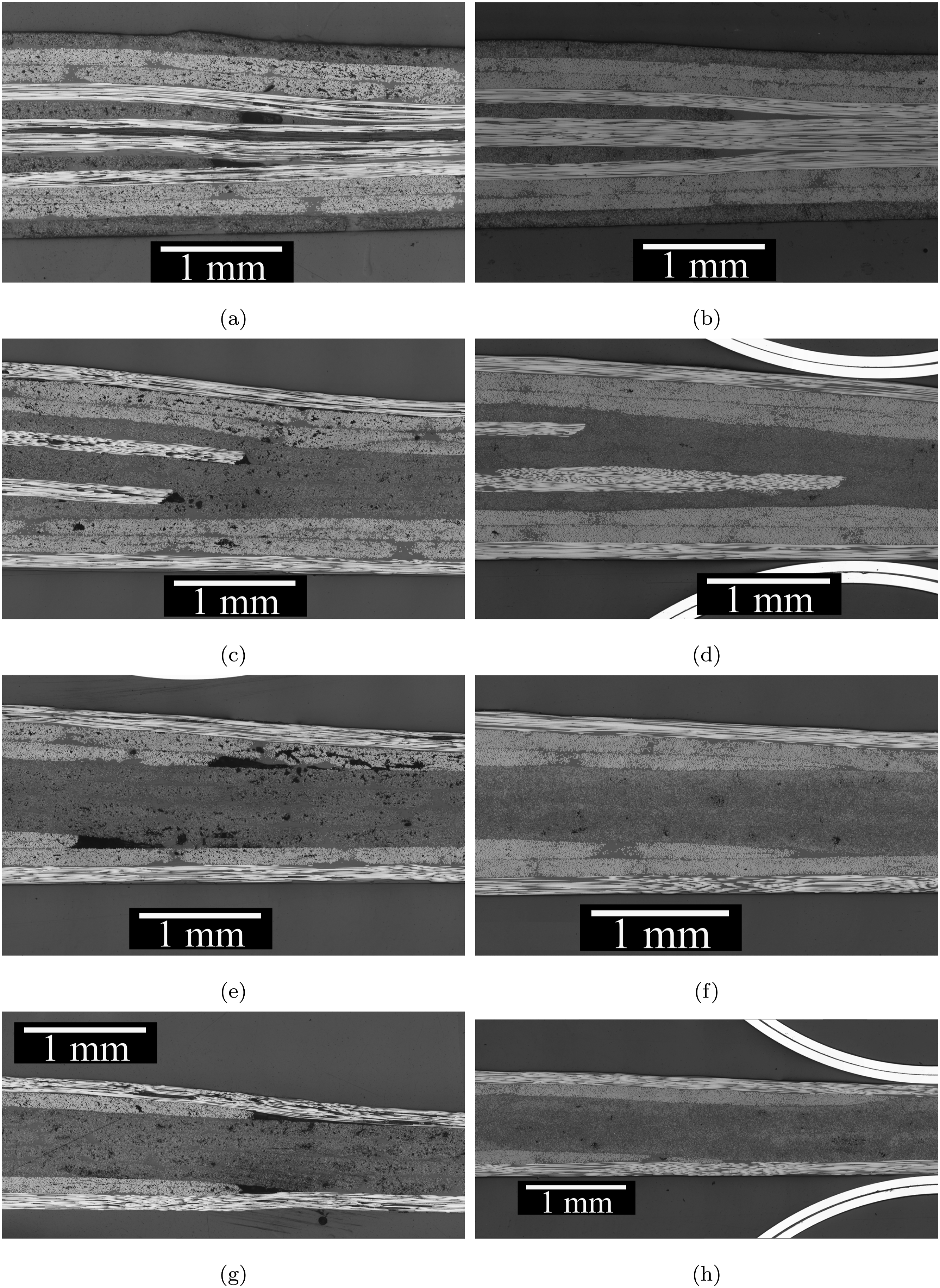
Similarly, Figure 16 presents the results for the TC1320 material system. The left and right columns of Figure 16 present the cross-sectional micrographs of AFP laid preforms and VBO post-consolidated laminates, respectively. Figures 16(a), (c), (e), and (g) showed the presence of void pockets and the intra-tape voids just after the placement. However, Figures 16(b), (d), (f), and (h) showed that the two-step consolidation enhanced the consolidation by assisting in void filling and removing intra-tape void. Cross-sectional micrographs TC1320 non-uniform thickness preform on the (left column), and VBO consolidated TC1320 non-uniform sections on the (right column).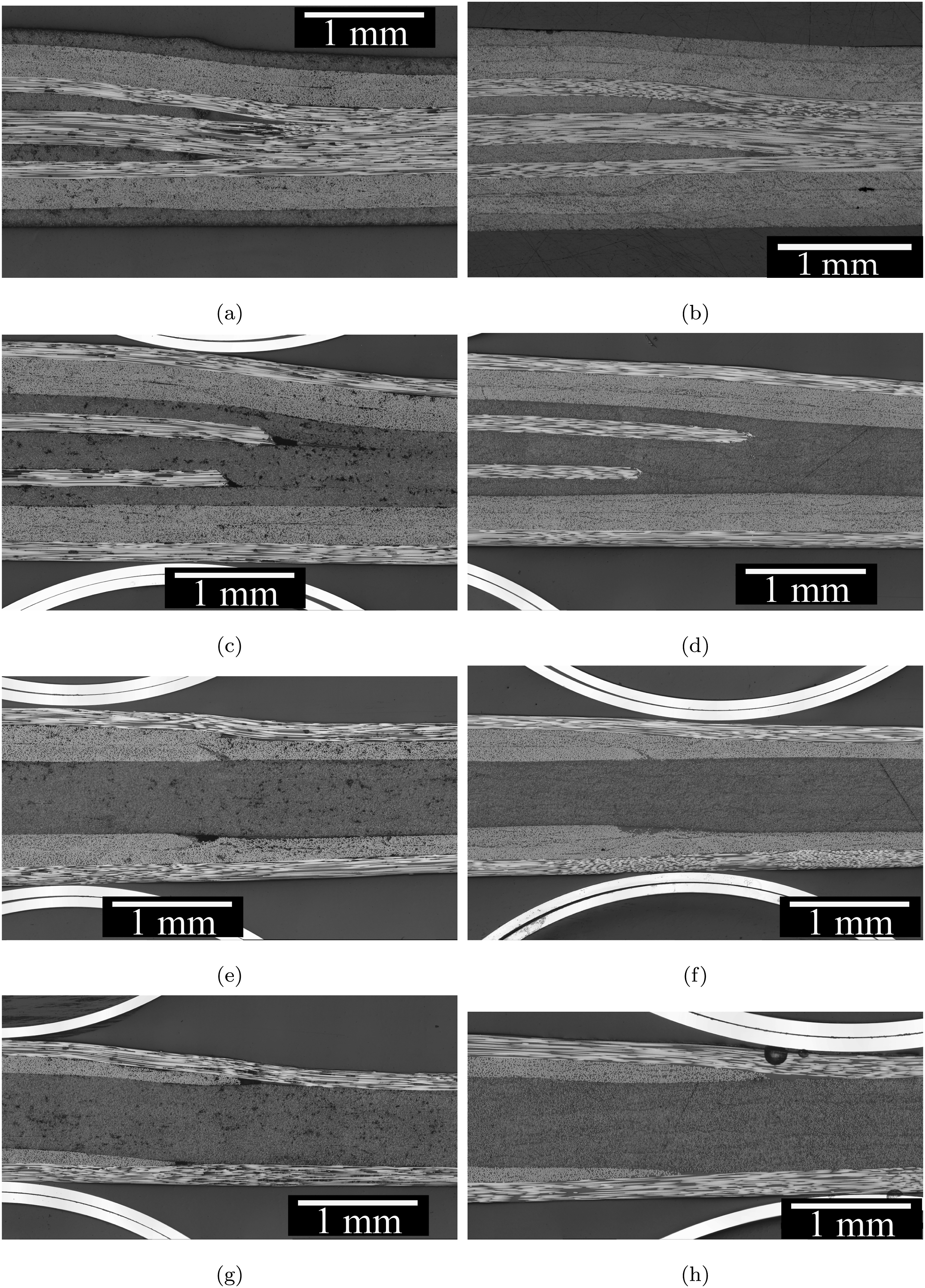
The void pockets can be filled by transverse squeeze, as illustrated in Figure 17(a), or by matrix bleed filling, as illustrated in Figure 17(b), or the combination. The orientation of the dropped ply and the covering plies majorly dictates the filling behavior. Schematic illustration of different flow mechanism. (a) Transverse squeeze of voids pockets. (b) Bleeding of the matrix into void pockets.
3
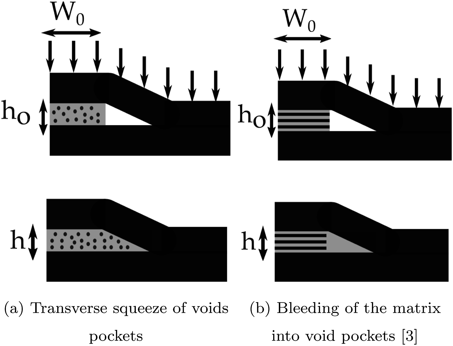
For example, in Figures 15(b) and 16(b), where a 90° ply is dropped, the dominant flow was transverse squeeze flow as the fibers of the dropped ply were parallelly aligned to the void pocket formed due to the dropped ply. In the case of a 0° ply drop, as in Figures 15(d) and 16(d), the transverse squeeze flow is restricted as the fibers of the dropped ply are oriented perpendicular to the drop. Either the matrix bleeds out the dropped plies, or material flow from the covering plies is required to fill these pockets. In the current case, the flow from the covering plies filled the void pockets. Further, as mentioned earlier, due to fixed cutting angles, any orientation of dropped ply between 0° and 90°, e.g., 45° or −45°, will result in a staircase-like edge or stepped edge. The stepped edges might result in non-uniformity in the size of the void pockets and demand for more material flow. It is observed from experimental results in Figures 15(f) and (h), 16(f) and (h) that the combination of flow, i.e., the transverse squeeze flow from the dropped 45 or -45° ply and the matrix bleed from the surrounding 90° plies led to filling of these void pockets.
To conclude, the formation of void pockets as a result of ply-drop, especially during rapid layup of tailored preforms using AFP, is inevitable. The two-step AFP and VBO consolidation experiments of non-uniform sections showed that for both APC and TC1320 material systems, 1 bar pressure is sufficient for filling these void pockets with no extended dwell times than a standard 30 min at 375°C.
Conclusion
From the experimental results of the two C/PEKK material systems investigated, it is clear that the one bar pressure is sufficient for filling gaps of 1 mm wide between tapes and void pockets in a tailored part as a result of dropping 0, 90, 45, or −45° orientation plies.
The glass plate setup used in this research was beneficial in real-time tracking of the gap closure. The gaps started to close at 300°C, much before the melt temperature of the tapes reported in the data sheets (i.e., around 343°C) for both material systems. Further, in one material system, the filling was faster, and it was completed at 350°C, whereas for the other material system, it took a bit longer and was completed only at 375°C. However, both the material systems showed that the gaps are easily filled during the VBO process without additional dwell time. Finally, the cross-sectional micrographs of the consolidated plies indicated that the dominant flow was a transverse squeeze to fill the gaps.
VBO consolidation of fiber-placed tailored preforms showed that the consolidation effectively fills the void pockets at the ply drop zones. The orientation of the dropped ply and covering plies majorly dictated the filling behavior. Further, the results ascertained that for the given material systems, the flow is not the biggest challenge during the VBO consolidation.
A first recommendation for future work is to understand the role of tape microstructure on gap-filling behavior. The gap-filling experiments demonstrated that the gap-filling rate differed for the two material systems, concluding that the microstructure of the tapes will play a role. Second, it is observed that ply-drop filling involves a more intricate process, combining squeeze and percolation flow from both the dropped ply and surrounding plies. A systematic evaluation, aided by (complex) numerical simulations, can be valuable in understanding this mechanism at the ply level. Such an evaluation could prove beneficial in optimizing ply-drop configurations, such as the angle of dropped plies, arrangement of covering plies, and ply-drop ratios, thereby minimizing void pockets.
Footnotes
Declaration of conflicting interests
The author(s) declared no potential conflicts of interest with respect to the research, authorship, and/or publication of this article.
Funding
The author(s) received no financial support for the research, authorship, and/or publication of this article.