
Abstract
Vacuum-bag-only (VBO) consolidation of automated fiber placed (AFP) thermoplastic composites can be a cost-effective processing route for large and complex thermoplastic composite structures. This paper explores the possibility of two-step AFP and VBO consolidation of advanced thermoplastic composites. Two commercially available carbon fiber reinforced Poly-Ether-Ketone-Ketone (C/PEKK) thermoplastic tapes were evaluated. Different process parameters were needed for the two material systems. Further, for the first time, an attempt was made to create in-plane air evacuation channels by deliberately introducing gaps between the tapes in the preforms during the placement. In the case of one material system, the VBO consolidation of preforms with and without gaps yielded good consolidation quality with less than 1% voids. In the other case, VBO consolidation of preforms with gaps showed a improved consolidation quality with less than 1% voids than the preform without gaps, indicating that the gaps possibly help accelerate the gas evacuation process.
Introduction
Currently, there is an increased interest towards the use of thermoplastic composites (TPCs) in the aerospace industry. TPCs are desirable because of their melt-processible nature that allows for high production rates, assembly through fusion bonding, recycling without the need for separating fiber and matrix, as well as their appealing mechanical properties compared to their thermoset counterparts.1–3 However, at present, the use of TPCs is still mostly limited to small press-formed ribs and cleats. In order to take a step forward and realize large-scale application of TPCs, the key is to develop affordable manufacturing technologies for large and complex TPC parts such as wing skins or fuselage sections. 4
Automated fiber placement (AFP) is a suitable manufacturing method for large and complex parts. The AFP process is highly automated, demanding little to no human intervention, while it also allows near-net shape manufacturing, minimizing material waste. Ideally, AFP is a one-step process where material consolidation is achieved during layup: a process referred to as an in-situ consolidation. However, to date, the in-situ consolidation process is not yet sufficiently technologically mature to consistently produce aerospace-grade parts.5–7 Therefore, at present, the aerospace industry relies on a two-step process where AFP is first used to lay up the preform at high deposition rates, which is then post-consolidated in a press, autoclave, or oven.8,9
The combination of AFP and press-forming is an effective route for rapid manufacturing of small and relatively simple parts.10,11 Further, AFP combined with autoclave consolidation is a benchmark process for large and complex parts.
6
The high pressures and longer processing time during the autoclave process will ensure the final part quality.
12
However, the autoclave process is expensive, and accommodating variable part sizes is challenging.
13
As a result, small parts are often processed in large autoclaves, increasing the final part production costs. Alternatively, the aerospace industry is banking on a two-step process that combines AFP with a cost-effective VBO consolidation step.
8
Figure 1 schematically illustrates the two-step AFP and VBO consolidation process. First, the TPC tapes are laid down at high-deposition rates to manufacture the preform. Subsequently, a VBO post-consolidation in an oven or on heated tooling follows to achieve void-free TPC parts. Schematic of a typical two-step AFP followed by VBO consolidation process route.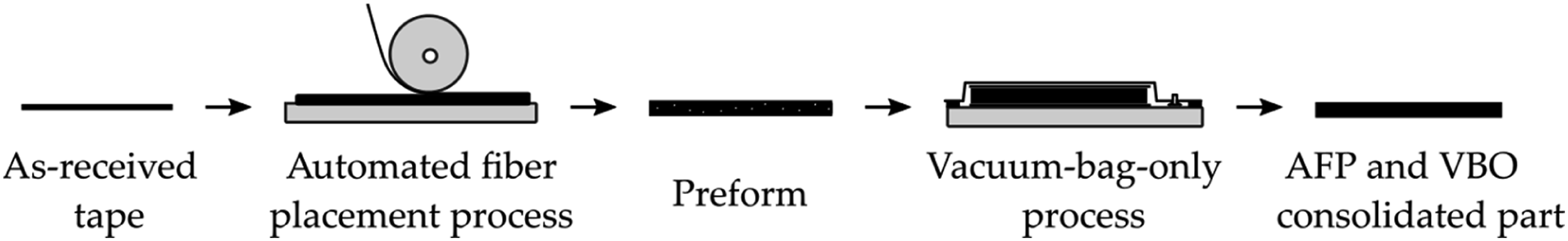
The VBO process does not employ external pressures, so the processing costs are lower than for the autoclave process. Further, the idea of heated tooling can address the problem of part size variability. However, VBO consolidation of TPCs is relatively immature, and the viability of combining the AFP process with the VBO post-consolidation step has not yet been explored extensively. Therefore, the current work focuses on exploring the possibility of the two-step AFP and VBO consolidation of high-performance TPCs.
Background
The consolidation quality of TPC parts is primarily judged based on the interlaminar bond strength, the degree of crystallinity and the void content. A good interlaminar bonding requires the diffusion of polymer chains across the ply interfaces at elevated temperatures. 14 The high placement rates used during preform manufacturing limit the time available for polymer chain diffusion and, hence, lead to insufficient interlaminar bonding. However, the post-consolidation VBO process offers a longer dwell time that will ensure adequate interlaminar bonding.
The degree of crystallinity depends on thermal history and, in particular, the cooling rates. 15 Achieving the required degree of crystallinity during the manufacturing of preforms via the AFP process can be challenging as the cooling rates are in the order of 100°C/s or higher.15,16 However, the cooling rates during the post-consolidation VBO process can be controlled and optimized to achieve the desired degree of crystallinity.
Finally, the void content. The three primary sources of voids are, voids present in the as-received tape material, air entrapment between the layers during preform manufacturing and the evaporation of volatiles from the tapes during the VBO consolidation process. Void removal mainly occurs during the VBO process as the available time during the AFP is insufficient. The two main mechanisms that govern void-free consolidation of TPCs during the VBO process are: i. Gas removal and ii. Filling of voids. Both are briefly discussed below.
Gas removal
The removal of gases from the voids is challenging, especially under low-pressure processing conditions, typical for the VBO process. The dominant mechanisms responsible for gas removal during the VBO process are dissolution and diffusion of gas through the matrix material and in-plane evacuation of the gases through the porous inter-layer pathways if present in the layup.17–19
The diffusion of gasses through a semi-crystalline polymer matrix such as polyether-ether-ketone (PEEK) is a slow process. The time for diffusion depends on the diffusion coefficients, the amount of gas to be diffused, which comprise both the entrapped air and possible volatiles released from the matrix during processing, and the diffusion length (approximately the thickness of the composite laminate). For example, consider an interlaminar void filled with oxygen gas present at the center of a 50-ply laminate with a ply thickness of 0.15 mm. Using the diffusion coefficient of oxygen in pure PEEK polymer at 380°C of 2.8 × 10⁻¹⁰ m2/S, the time required for an oxygen molecule to diffuse to the surface is approximately 5 h. For the complete removal of the oxygen gas from the void will be much longer. 20
In-plane air evacuation is another important void removal mechanism mentioned in the context of VBO processing. For example, Zhang et al.21–24 performed studies on the VBO consolidation of hand-stacked 72-ply thick thermoplastic composites and concluded that air evacuation through small channels between the unidirectional (UD) tapes prior to consolidation is vital. In their case, the channels were caused by the surface roughness of the tape material, while by hand stacking, the authors ensured that they remained open. However, in the case of preforms laid down using the AFP process, the tapes are melted to stick, likely closing any interlayer channels.
One way to create in-plane airflow in fiber-placed structures is by deliberately creating gaps between the tapes during the placement, as shown in Figure 2. Though the idea of in-plane air channels, and their effect, is not new in the case of thermoset prepregs, the manner in which the channels are introduced in preforms during the fiber placement is unique to this paper. Schematic of AFP placed cross-ply preform with well-defined gaps used as in-plane air channels (dotted lines) during the post-consolidation process.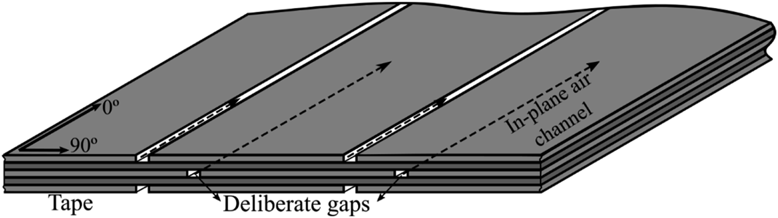
In the case of thick laminates, where the time required for diffusion is long, in-plane channels can be of importance. The entrapped air and volatiles can diffuse to these channels and evacuate to the part’s perimeter prior to consolidation. The authors are aware that the creation of gaps in the preforms will lead to variation in local thickness and fiber-matrix distribution after consolidation. However, the goal is to understand if the gaps assist in in-plane air evacuation during the VBO consolidation.
Filling of voids
Simultaneously with the gas removal process, the void space has to be filled by the flow of the composite material. The two primary flow mechanisms expected here are the transverse squeeze flow of tapes (affine flow) and matrix bleeding from tapes (percolation flow).25–27 Swamy et al. 28 performed VBO studies on thermoplastic composite parts involving ply drops, and it was concluded that gas removal was a more significant challenge than filling the drop zones.
Objective
VBO consolidation of hand-laid TPCs has received some attention in the literature. However, for large and complex parts, advanced layup techniques such as the AFP process should be employed. The possibility of combining the AFP process with VBO consolidation has received little attention. Further, the tape material will play a crucial role in choosing processing parameters. For example, based on the supplier, the tape materials with similar constituents will show variations in the properties, such as diffusion coefficients and the presence of volatiles, influencing the final consolidation quality. 19 This work explores the possibility of two-step AFP and VBO consolidation of C/PEKK TPCs, with the main focus on developing a process window. Two commercially available C/PEKK tapes are considered to investigate the role of input tape material on the quality of two-step AFP-VBO consolidation laminates. Further, as discussed earlier, in-plane air evacuation via interlayer air channels plays an important role in void reduction. However, in the case of preforms manufactured through automated fiber placement, the tapes are bonded together, closing off any channels. Therefore, an attempt is made to engineer in-plane channels in fiber-placed preforms by deliberately providing gaps between the tapes during placement. The efficacy of this strategy will be evaluated experimentally.
Experiments
In the two-step manufacturing process, the as-received tapes are first laid down using an AFP process to produce preforms. Later, the preforms are subjected to a VBO consolidation process with the aim to improve the quality of the final laminate.
Material
UD C/PEKK slit tape of width 6.35 mm from two different suppliers is used: APC (Solvay) and Cetex® TC1320 (Toray Advanced Composites). The tapes consist of AS4D fibers with a fiber volume fraction of around 60%, and have the melting (Tm) and processing temperature (Tp) of around 340°C and 375°C, respectively. Although the tapes' constituents and processing temperatures are very similar, the tape morphology, such as surface roughness and fiber-matrix distribution, and physical characteristics, such as presence of volatiles and diffusion properties differ substantially.
19
Swamy et al.
19
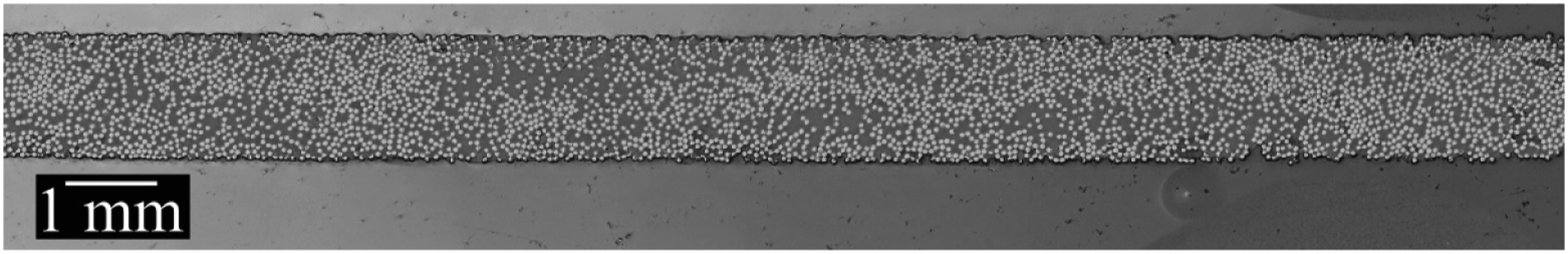
performed thermogravimetric analysis (TGA) on the tapes and found that the overall mass loss in APC and TC1320 tapes are 0.19% and 0.12%, respectively. The loss in mass is attributed the amount of the volatiles released. Figures 3 and 4 present the cross-sectional micrographs of APC (PEKK-FC) and TC1320, respectively. The morphological distinction between tapes is evident from the cross-sectional micrographs. Cross-sectional micrograph of Solvay APC tape. Cross-sectional micrograph of Toray TC1320 tape.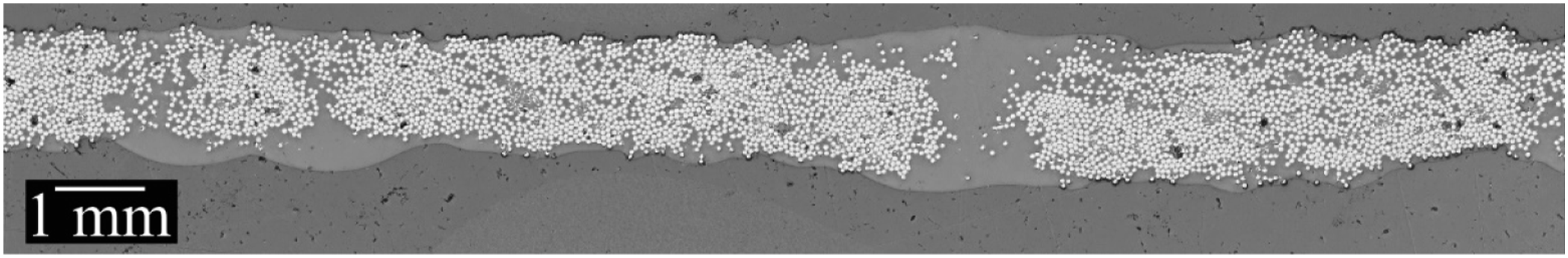
Manufacturing
For this study, two APC and five TC1320 24-ply [0/90]6s cross-ply laminates were manufactured using the two-step AFP and VBO process. In addition, one APC and one TC1320 24 ply [0/90]6s cross-ply laminates were manufactured via a two-step AFP and autoclave consolidation process; these are treated as a benchmark. The details regarding the preform layup process and consolidation process are provided in the following section.
Preform manufacturing
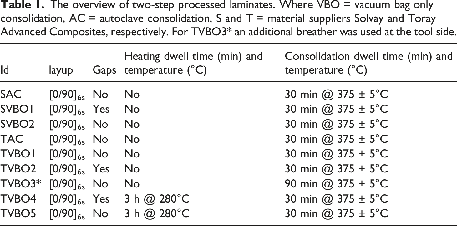
The overview of two-step processed laminates. Where VBO = vacuum bag only consolidation, AC = autoclave consolidation, S and T = material suppliers Solvay and Toray Advanced Composites, respectively. For TVBO3* an additional breather was used at the tool side.
Consolidation process
The preforms were consolidated using an oven or an autoclave. Autoclave consolidated laminates are considered the benchmark. Figure 5 illustrates the vacuum-bag setup used. It consists of a 600 mm × 600 mm steel base plate. The preform was placed on the base plate with a porous release film (UPILEX® 25S), with a thickness of 25 μm, on the top and bottom of the preform. A glass wool breather is placed around the perimeter of the preform. On top, 8 layers of woven glass fabric were used as a breather. Finally, 50 μm polyimide film was used as a vacuum bag which was sealed using a high-temperature A-800-3G AIRTECH sealant. For one particular consolidation experiment, the bag setup was slightly modified with an additional glass fabric breather on the bottom side of the preform as well to enhance the diffusion process. The typical setup used for the VBO consolidation process.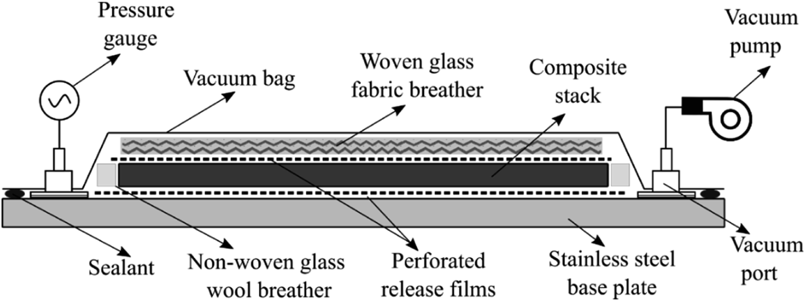
For VBO consolidation, the bag was placed in a convection oven without any positive external pressure. A vacuum pump is used to maintain a pressure of less than 0.05 bar in the bag. The laminates were processed at 375 ± 5°C with a heating and cooling rate of around 3–5°C/min. Processing parameters are varied between the experiments. For example, some laminates were processed with an additional heating dwell at 280°C for 3 h to provide sufficient time for gas removal. Table 1 presents an overview of the laminates manufactured.
The bag configuration for autoclave consolidated laminates remained the same as in Figure 5. These laminates were consolidated in an autoclave at 7 bar pressure following the same temperature cycle used for VBO consolidation.
Consolidation quality
The consolidation quality of the laminates was judged by the void content and the interlaminar bond strength. First, cross-sectional microscopic inspection and density measurement techniques were used to evaluate the void content. Later, short beam strength (SBS) tests were performed to measure the interlaminar bond quality.
Void content
Samples of 20 mm × 20 mm were cut from the consolidated laminates for cross-sectional microscopic investigation. Two micrographic images were taken for each case, of which one image is presented for each case in the results. A Keyence VHX-5000 digital microscope was used for capturing the micrographic images at 300× magnification. Further, density measurements were performed according to ASTM D792 on five 20 mm × 20 mm samples per laminate to quantify the void content. The void content of the samples (Vv) was calculated by measuring the density ρ of the samples and comparing it to the reference density ρ0 of a benchmark autoclave sample. The void fraction was determined as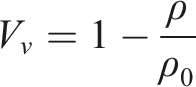
Short beam strength
Short beam strength (SBS) testing was used to characterize the interlaminar bond strength. A minimum of 5 samples were cut from the preforms and the consolidated laminates. SBS tests were performed on an Instron 8500 universal testing machine according to ASTM D2344 with a cross-head displacement rate of 1 mm/min. The fiber direction on the surfaces of the samples was parallel to the span length. The force-displacement curves were recorded, and eventually, the SBS was calculated using the peak load (Pmax) as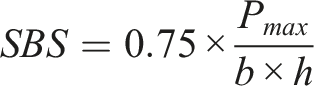
Results
Microscopy
Figures 6–8 provide an overview of the micrographs of the APC preforms and the consolidated laminates. Figures 6(a) and (b) are the micrographs of the preforms without and with intentional gaps, respectively. The micrographs show that there are no interlaminar voids except for the gaps that were deliberately included for air evacuation. However, intralaminar voids are present throughout the cross-section. Figures 7(a) and (b) present the micrographs of VBO consolidated laminates without and with gaps, respectively. The micrographs show that VBO consolidation of both preforms with and without gaps had no interlaminar voids. Intralaminar voids were present, however, less severe than in the preforms. Further, the gaps engineered for air evacuation in the preforms were filled during the VBO consolidation. The APC tape material showed qualitatively an increase in the consolidation after the two-step AFP and VBO process. Finally, Figure 8 provides the micrograph of the benchmark autoclave consolidated laminate. It is evident from the micrograph that there are no interlaminar or intralaminar voids. Cross-sectional micrograph of APC preform, (a) without gaps and (b) with gaps. Cross-sectional micrograph of VBO consolidated APC laminate with 30 min dwell, (a) without gaps and (b) with gaps. Cross-sectional micrograph of autoclave consolidated APC laminate (SAC).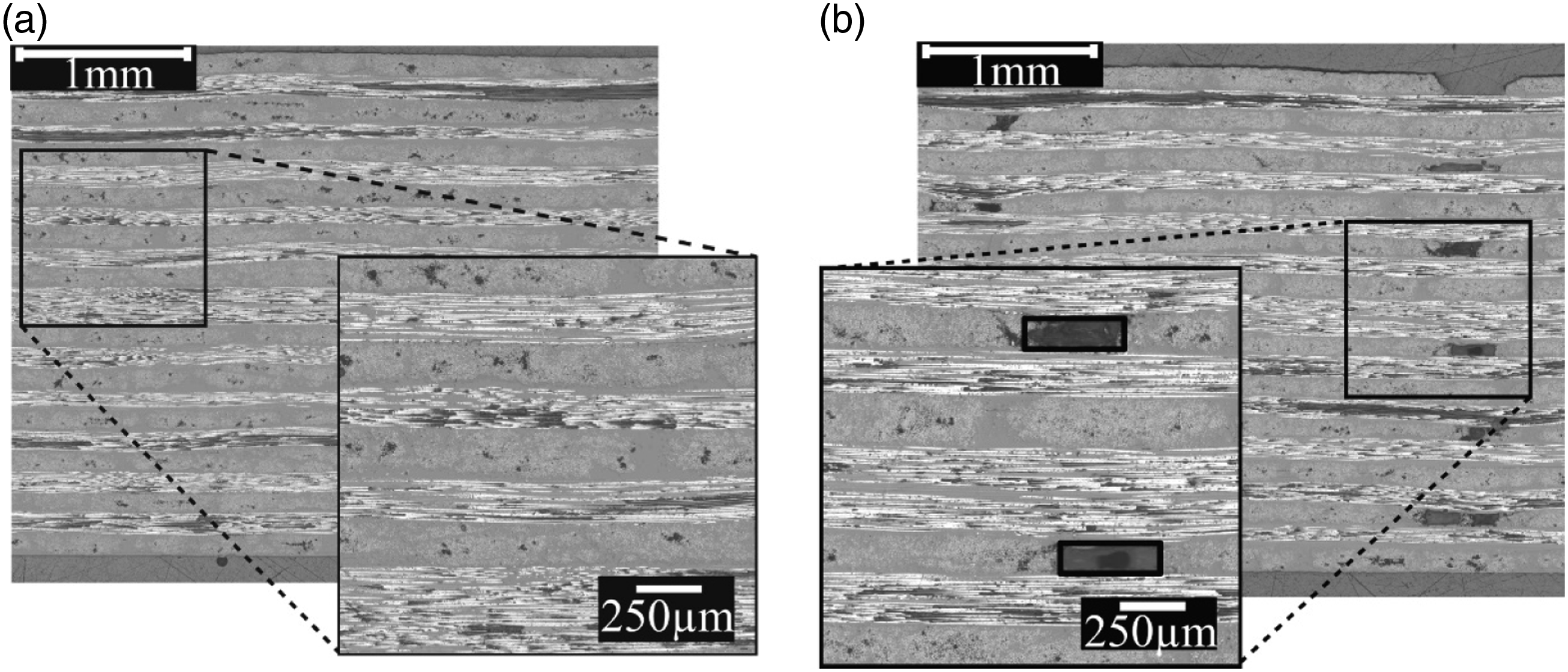
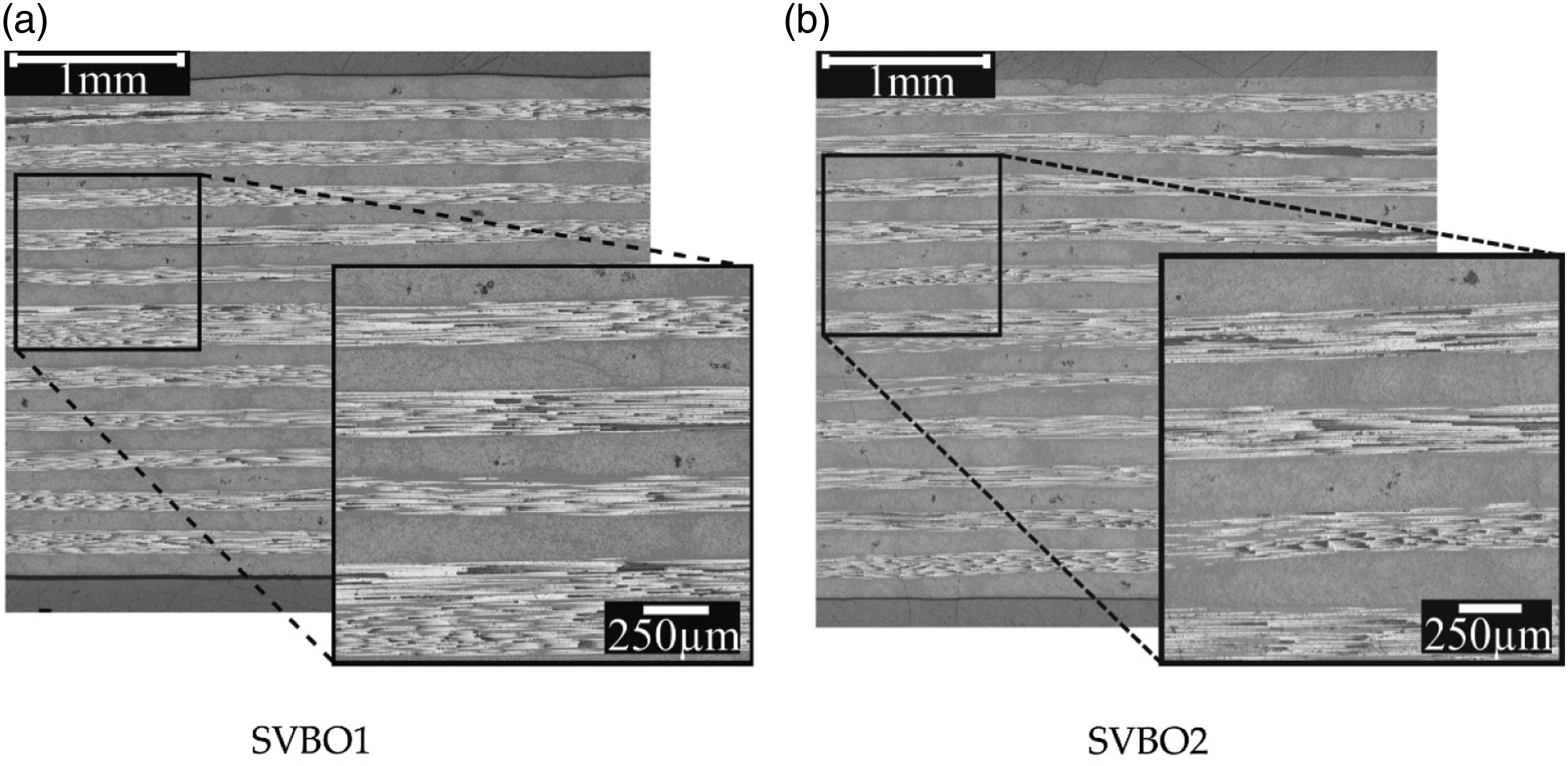
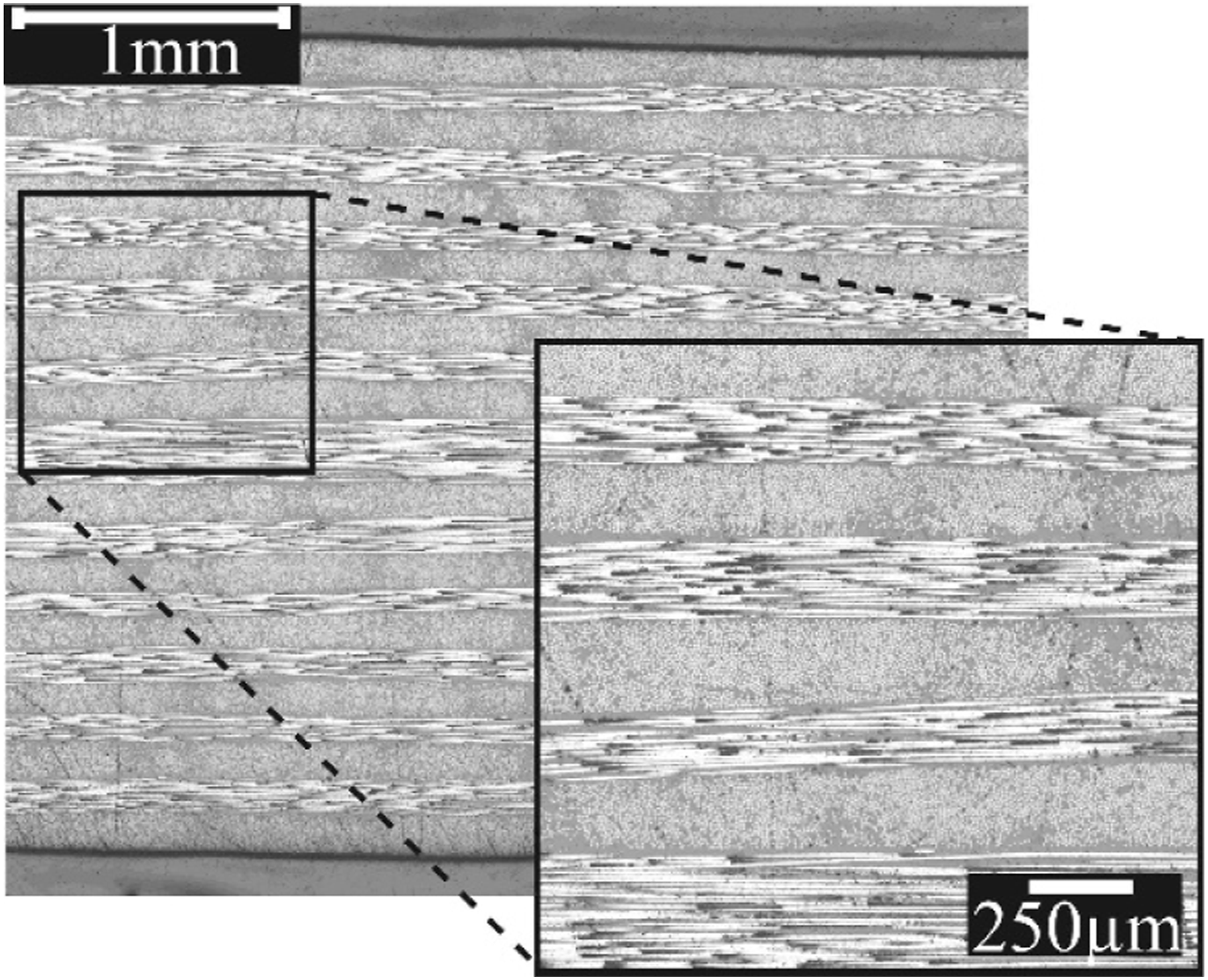
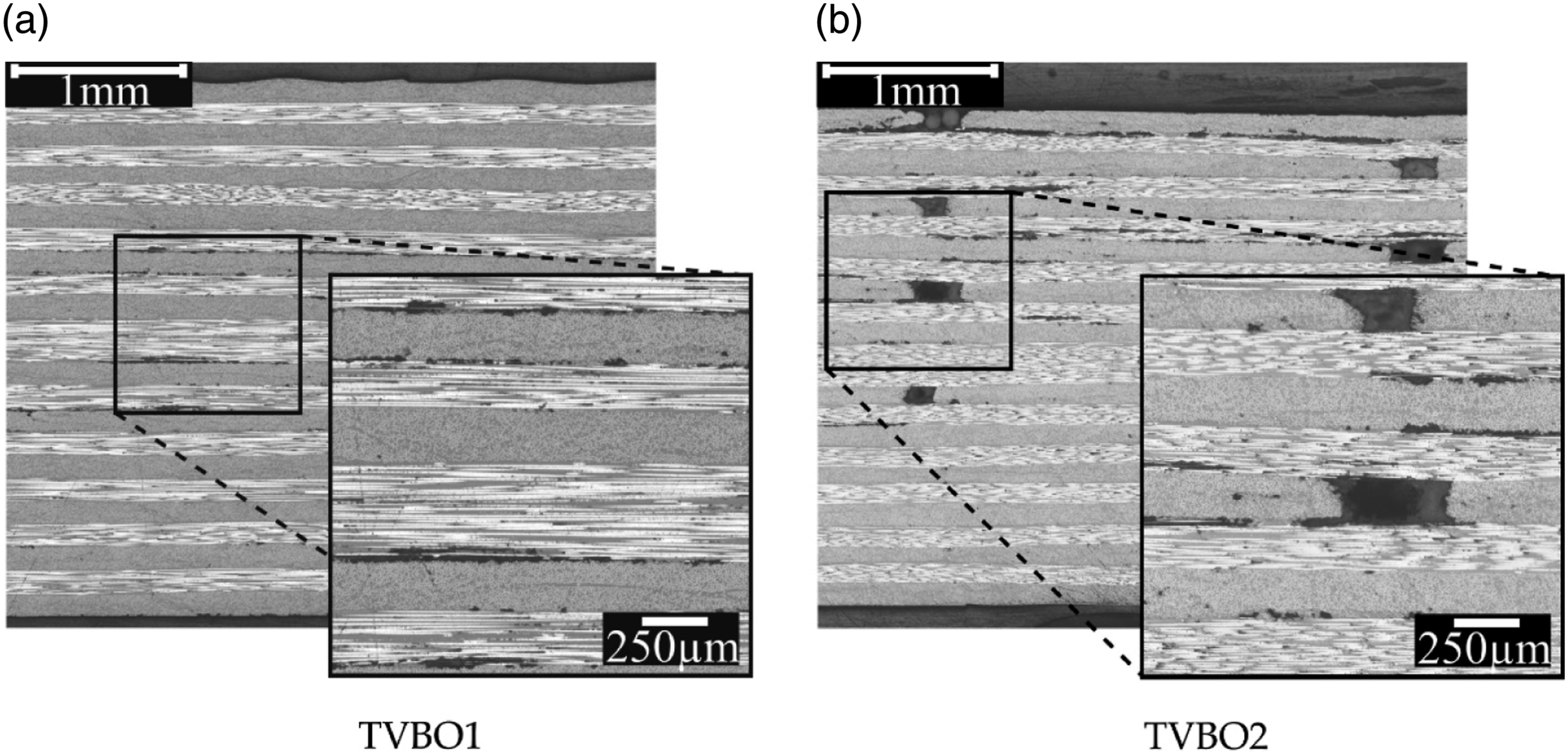
Figure 9–12 provide an overview of the micrographs of the TC1320 preforms and the consolidated laminates. Figures 9(a) and (b) present the micrographs of the preforms without and with gaps, respectively. The micrograph of the preform without gaps shows the presence of small interlaminar voids and intralaminar voids. In addition, a few minor gaps were observed between the tapes. Figures 10(a) and (b) provide the micrographs of VBO consolidated laminates without and with gaps, respectively. Figure 10(a) shows the presence of interlaminar voids, which were more confined to the mid-plane of the laminate. An interesting observation is that the air entrapment during the preform manufacturing was minimal, but interlaminar voids were found after the VBO process. One possible explanation for this can be the evaporation of volatiles during the VBO processing. Figure 10(b) corresponds to the micrograph of VBO consolidated laminate with gaps which showed decreased consolidation quality with interlaminar voids and gaps unfilled towards the top section (i.e. bag side) of the laminates. Figure 11(a) provides the micrograph of the VBO consolidated laminate without gaps where the dwell time was changed from 30 min to 90 min, and the bag setup was modified to add an extra breather on the bottom side of the laminate during the VBO process. The micrograph indicates an increase in the consolidation quality with no intralaminar or interlaminar voids. Cross-sectional micrograph of TC1320 preform, (a) without gaps and (b) with gaps. Cross-sectional micrograph of VBO consolidated TC1320 laminate with 30 min dwell @ 375°C, (a) without gaps and (b) with gaps. Cross-sectional micrograph of VBO consolidated TC1320 laminate (a) without gaps and with a modified bag set up consolidated @ 375°C with a 90 min dwell, and (b) without gaps and with an additional heating dwell of 3 h @ 280°C. Cross-sectional micrograph of (a) VBO consolidated TC1320 laminate with gaps, and with an additional heating dwell of 3 h @ 280°C and (b) autoclave consolidated TC1320 laminate.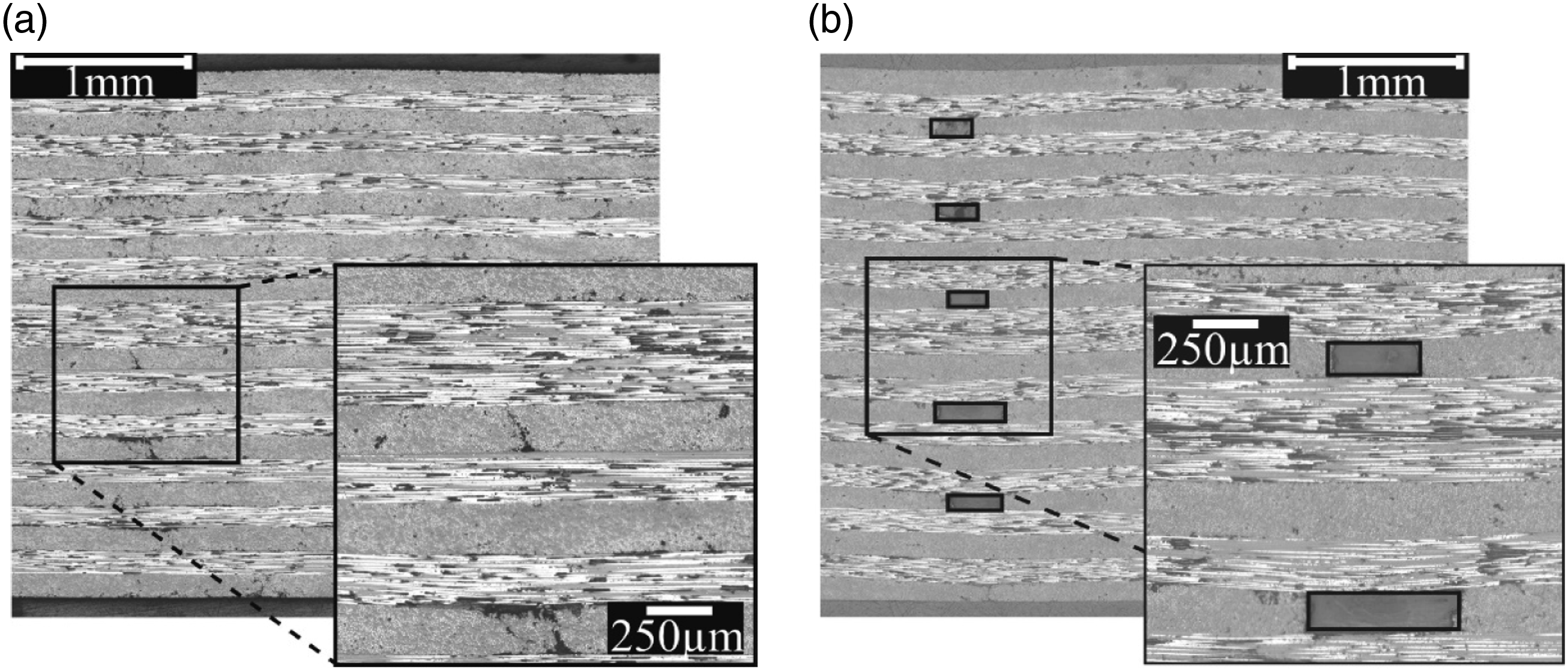
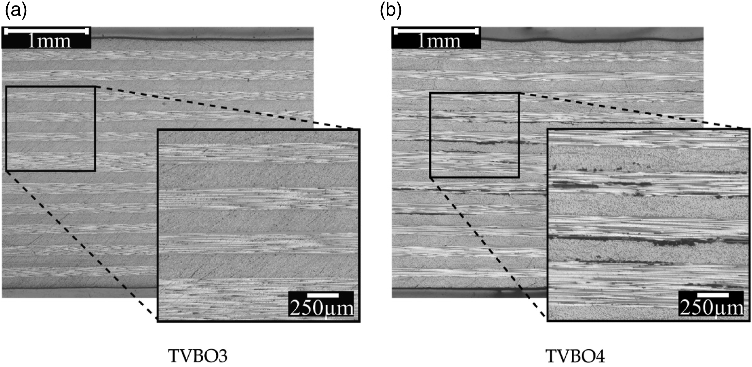
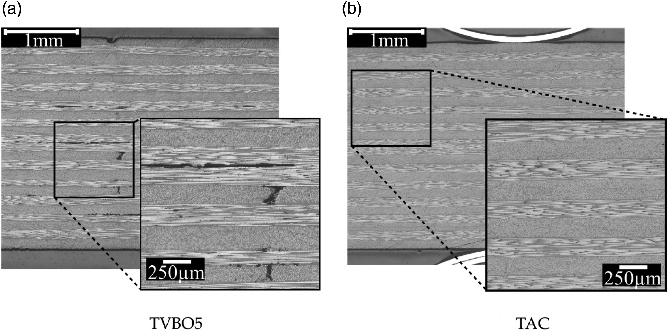
Figures 11(b) and 12(a) show the micrographs of VBO consolidated laminated with an additional heating dwell at 280°C for 3 h to provide sufficient time for gas removal. Figure 11(b) corresponds to VBO consolidated laminate without gaps and with an additional dwell. It is seen from the micrographs that the consolidation quality with additional heating was increased. Similar to Figure 10(a), interlaminar voids were observed near the mid-plane of the laminate. Figure 12(a), which corresponds to the micrograph of a VBO consolidated laminate with gaps and an additional heating dwell, showed an increase the consolidation quality compared to the laminates without gaps with a low interlaminar void content. Further, it was observed that the gaps at some locations were not entirely filled.
Finally, Figure 12(b) is the micrograph of the benchmark autoclave consolidated laminate. The micrograph indicates a good consolidation with no interlaminar or intralaminar voids.
Density measurement
The void content has been quantified based on the laminate’s density. As the cross-sectional micrographs confirmed that the autoclaved laminates showed no voids, these were considered the void-free reference from which ρ0 was determined. Figure 13 presents an overview of the void content of all the manufactured laminates. Estimated void content based on density measurement.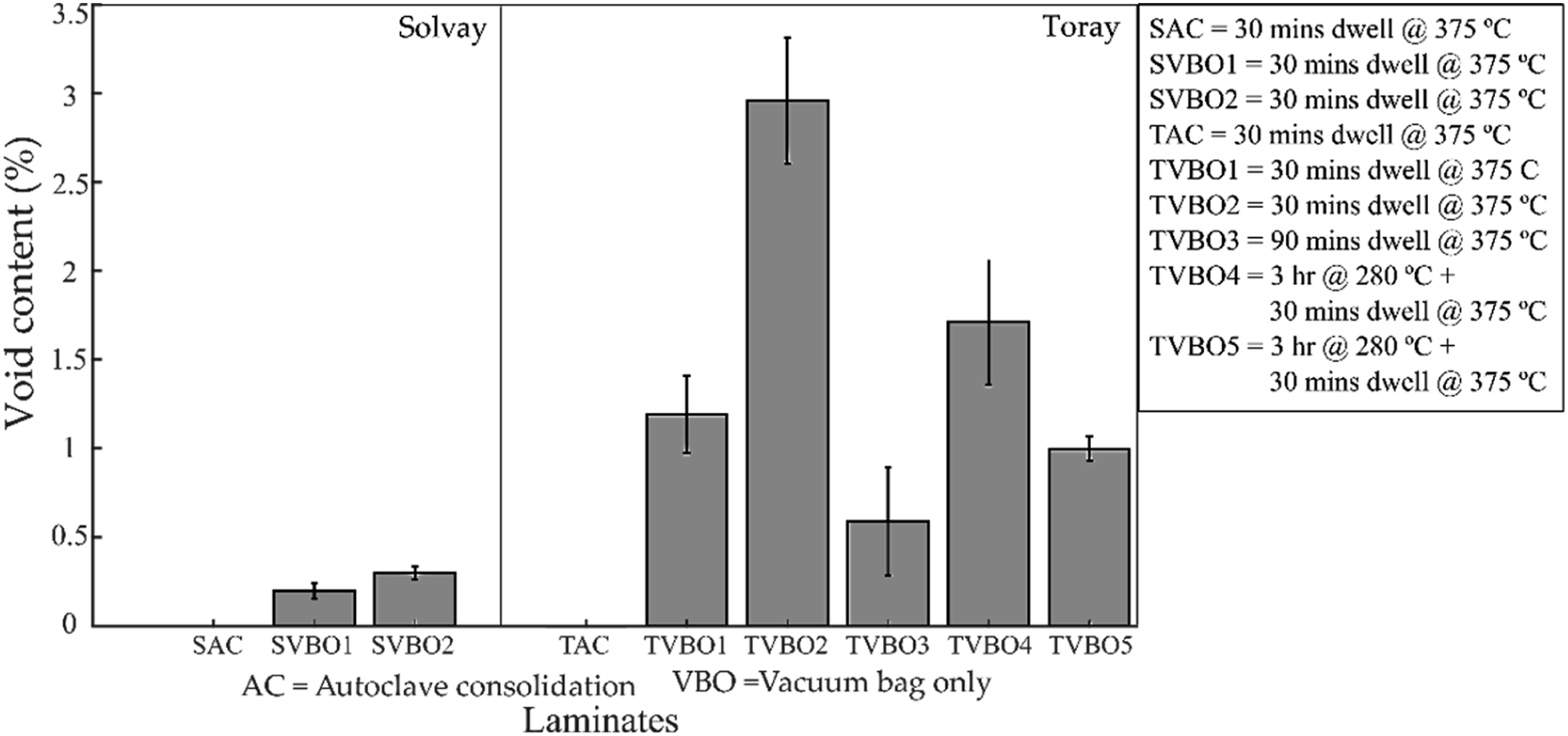
The VBO consolidated APC laminates showed good consolidation quality with less than 0.3% void content in the case of both preforms with gaps and without gaps. In the case of TC1320 laminate, the void content depends on the chosen consolidation parameters. A void content of less than 1% was achieved in two cases, namely: i. When the laminate was processed with an extended consolidation dwell time of 90 min using a breather on top and bottom during the VBO process (TVBO3), and ii. In the case of a preform laid down with gaps and the VBO process included a heating dwell at 280°C for 3 h and a consolidation dwell at 375°C for 30 min (TVBO5). Here, the breather was only on the bag side, unlike in the case of TVBO3. It is acknowledged that using breathers on both the top and bottom sides is not always practical in aerospace manufacturing.
Short beam strength
Figure 14 provides an overview of the measured short beam strength values (SBS) of the preforms and consolidated laminates. Measured SBS of preforms and consolidated laminates.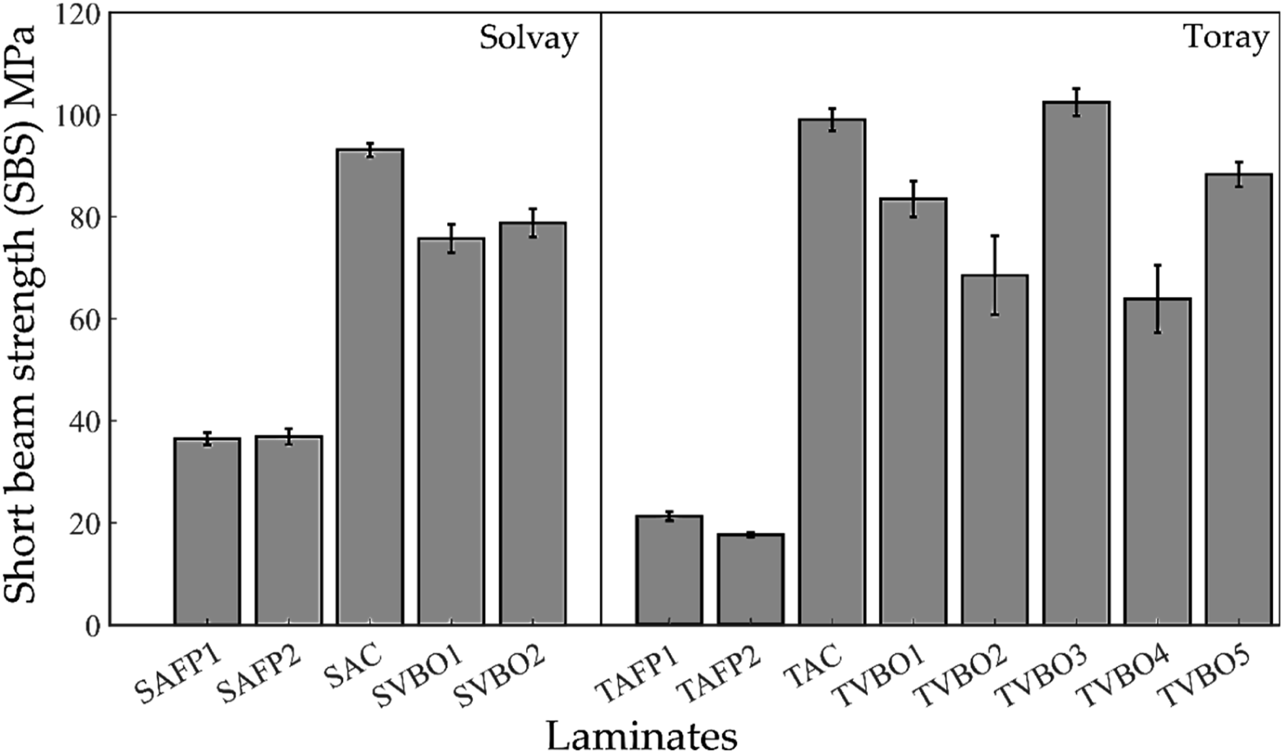
It is clear that, in the case of both APC and TC1320, the autoclave consolidated laminates showed the highest SBS of around 93 MPa and 100 MPa, respectively. Therefore, SAC and TAC can be considered a benchmark. The AFP preforms showed decreased SBS strengths of only 40% and 20% of the benchmark for APC and TC1320 laminates, respectively. The poor SBS can be attributed to the relatively high placement speed of 200 mm/s, which limits the time for the autohesion process.6,29
The VBO consolidated APC laminates demonstrated significant improvement in SBS compared to the preforms, with SBS values of 75 MPa and 78 MPa for the preforms with and without gaps, respectively. This is just over 80% of the autoclave benchmark value.
In the case of TC1320, the TVBO3 laminate with an extended consolidation dwell of 90 min and breather placed on top and bottom during the VBO consolidation showed an SBS value of around 100 MPa, which is similar to the benchmark. TVBO5, the laminate with gaps and an additional heating dwell at 280°C for 3 h, showed an SBSs value of 89 MPa, which is just 10% lower than the benchmark. The SBS of TVBO1 was 83 MPa, 17% decrease compared to the benchmark, while TVBO2 and TVBO4 showed relatively lower SBS values of 68.5 MPa and 63.86 MPa, respectively.
Discussion
Void formation during the VBO process
The cross-sectional micrographs of the TC1320 preforms manufactured via AFP, provided in Figures 9(a) and (b), showed that there was little to no air entrapped between the tapes in the form of interlaminar voids in the preforms. However, the cross-sectional micrographs of the VBO consolidated laminates as, for example, provided in Figure 10(a), showed the presence of interlaminar voids. A possible explanation for the formation of these interlaminar voids during VBO consolidation is the evaporation of volatiles, such as moisture or solvents from the tape material. Further, the interlaminar voids were concentrated towards the laminate’s mid-plane, indicating that void removal is governed by through-thickness diffusion and that the time available for consolidation was too short.
Void reduction during the VBO process
The two mechanisms responsible for gas removal during the VBO process are i. Dissolution and diffusion, and ii. In-plane air evacuation. Both will be discussed here with respect to the obtained experimental results.
Dissolution and diffusion
Two cases resulted in good consolidation with less than 1% void content. i. APC laminate, SVBO1, consolidated with a dwell time of 30 min, and ii. TC1320 laminate, TVBO3, consolidated with an extended dwell time of 90 min, where the bag setup was modified with an additional breather on the tool side to enhance the diffusion process. In both these cases, the preforms were manufactured without gaps restricting any possibilities of in-plane air evacuation. Gas removal thus mainly relied on through-thickness diffusion. Even though the gas removal mechanism in both cases was limited to through-thickness diffusion, different processing times and bag setups were needed depending on the tape material. There may be several causes for the difference. First, although both tapes comprise a PEKK matrix, the exact formulation may differ. Therefore, the diffusion coefficient of the tapes may be different. Second, the volume of gas that needs to be removed may be different. It is essential to realize that the gases in the preforms include both the entrapped air and the volatiles released from the tape during the consolidation process.
In-plane air evacuation
This work attempted to create in-plane air channels by deliberately introducing gaps between the tapes to facilitate air evacuation. In the case of APC material, preforms with and without gaps showed an excellent quality with less than 1% voids after VBO consolidation. Therefore, a 24-ply thick APC laminate can be consolidated with or without gaps within a practically feasible cycle time.
In the case of TC1320, the gaps did not prove to be efficient for the TVBO2, which was the laminate consolidated with a dwell of 30 min at 375°C. As a result, there were interlaminar voids and unfilled gaps towards the bag side of the laminate. However, the preforms with gaps which were consolidated with an additional heating dwell of 3 h at 280°C (TVBO5), showed an improved quality. The resulting void content was less than 1%, and the consolidation quality was enhanced compared to the laminate with similar processing parameters but without gaps (TVBO4). The in-plane channels seemed to assist in evacuating volatiles during the heating dwell. However, there were some locations where the gaps needed to be fully filled. Optimizing the size of the gaps for effective air evacuation and filling can result in the complete filling of gaps.
Conclusion
This paper presented a study on the two-step AFP and VBO consolidation process for advanced thermoplastic composites. First, preforms were laid down at deposition rates of 200 mm/s. Subsequently, the preforms were subjected to a VBO consolidation step in a convection oven. Two commercially available high-performance thermoplastic composite C/PEKK tapes, namely Solvay APC (PEKK-FC) and Toray Cetex® TC1320, were used. Although the tapes look similar on the datasheets, they varied in terms of surface morphology, fiber-matrix distribution, intralaminar voids and volatiles. Both tape materials were successfully consolidated using a two-step AFP and VBO process. However, one material demanded an extended consolidation dwell time of 90 min at 375°C and an additional breather on the tool side during VBO processing, which is rare in the aerospace industry. Further, in this work, for the first time, an attempt was made to create in-plane air channels by deliberately introducing gaps between the tapes during preform manufacturing. In the case of the TC1320 material system, VBO consolidation of preforms with gaps and an additional heating dwell at 280°C for 3 h showed improved consolidation quality compared to preforms without gaps, suggesting that the gaps help in accelerating the air evacuation process.
A first recommendation for future work is the extension of the two-step AFP and VBO consolidation approach to large and more complex structures, as most of the work in this research was focused on small 300 mm × 300 mm flat laminates. Second, the layup speed used in the current study is 200 mm/s. In the future, the layup speed can be maximized to 1 m/s and above to achieve truly rapid layup conditions. Finally, the gaps in the preforms seem beneficial, however, they were not optimized. Therefore, it is worth optimizing the gaps for air evacuation and, at the same time, easy to fill during the VBO process.
Footnotes
Declaration of conflicting interests
The author(s) declared no potential conflicts of interest with respect to the research, authorship, and/or publication of this article.
Funding
The author(s) received no financial support for the research, authorship, and/or publication of this article.