
Abstract
The current study is focused on understanding the role of different void removal mechanisms in VBO processing of advanced thermoplastic composites. For this purpose, two commercially available Carbon/Poly-Ether-Ketone-Ketone (C/PEKK) tape materials were evaluated, distinct in morphologies, such as surface roughness and fiber-matrix distribution, and physical characteristics, mainly the presence of volatiles. The VBO consolidation results proved that the void reduction and removal mechanisms varied depending on the tape material. However, restricting the void reduction mechanism to dissolution and diffusion alone. Depending on the tape material, a significant difference in the consolidation dwell time was observed to achieve <1% void content parts. Thus, indicating that despite the tapes having the same polymer matrix, they differ in their diffusion behavior. The difference in the times required for consolidation may be due to the following. Firstly, the diffusion coefficients may be different for the two tapes. Although the matrix material in both tapes is PEKK, the exact formulation is unknown. Secondly, the volume of gases, which comprises entrapped air and the volatiles that evaporate during the process, that need to be removed maybe be different.
Introduction
At present, thermoplastic composites (TPCs) are gaining significant attention from the aerospace industry because of their favorable processing and mechanical properties. The unique benefit of TPCs is their melt-processable nature that allows for higher production rates, assembly through fusion bonding, and recycling without separating fiber and matrix.1–4 Moreover, they also exhibit a higher toughness compared to their thermoset counterparts. Initially, the use of TPCs was restricted to small press-formed ribs and cleats, but, in the recent past, TPCs have been used in the control surfaces of the Gulfstream G650 and the wing leading edges of Airbus A380.5,6 The current challenge is the development of affordable manufacturing technologies, which will play a key role in further extending the use of TPCs for large and complex primary aircraft structures, such as wings or fuselage sections. 6
To date, large thermoplastic composite parts for aerospace applications are manufactured using autoclave consolidation (AC). This process, however, is expensive, and it is difficult to accommodate part size variability. As an alternative, in-situ consolidation via an automated fiber placement (AFP) process can be considered. However, this process currently lacks the technological maturity to produce aerospace-quality parts, and often the AFP process is combined with an autoclave consolidation cycle to enhance the quality of the part. 7 Therefore, the aerospace industry is banking on a two-step process where the AFP is used to lay up large and complex structures followed by vacuum-bag-only (VBO) post-consolidation, in an oven or on heated tooling eliminating part variability due to human interference as well as costly autoclave processing.8,9
Even though the thermoset industry has been using VBO processes for a long time, VBO consolidation for thermoplastic composites is still relatively immature. According to the authors, not many studies on VBO processing of high-performance TPCs are recorded. Zhang et al. 10 performed studies on AS4D/PEEK tapes and highlighted that in-plane air evacuation is a dominant air removal mechanism during VBO consolidation. It was shown that hand stacking of unidirectional (UD) TPC tapes resulted in inter-layer air channels with the tape’s surface roughness dictating the channel size distribution and, thus, the in-plane permeabilities. However, not all commercially available tape surfaces provide a similar roughness. In addition, in the case of preforms manufactured through automated fiber placement, the tapes may be melted to stick, closing off any channels. As such, consolidation in these cases cannot rely on inter-layer air evacuation anymore and is governed by other mechanisms. This study aims to identify these mechanisms and their importance for two commercially available tape materials. Various VBO consolidation experiments were designed to isolate and analyze the dominant mechanisms needed to achieve void-free consolidation. The consolidation quality is mainly judged based on ultrasonic inspection, microscopic inspection, and density measurements. Though the tapes used in the current work are not dedicated Out-of-Autoclave (OoA) tapes, the results from consolidation experiments can still provide insight and lead to the development of the processing and material guidelines. Before proceeding to the experimental section, a brief theoretical background is presented to understand the source of voids and potential void removal mechanisms that play a role during VBO consolidation.
Theoretical background
The consolidation quality is judged based on various aspects such as degree of crystallinity, interlaminar bond strength, void content, etc. 11 Given the low processing pressures, the main challenge for VBO consolidation is to achieve a low void fraction in the final part. 12 For that purpose, the authors restrict the discussion to voids only. There are two aspects to consider, namely i. the source of voids and ii. the void removal mechanisms. Both will be discussed shortly in the following.
Void sources
The term void refers to an unfilled region in the composite material. 13 Gas entrapment during manufacturing is one of the main causes of voids in composites.12,14 Voids are classified as intra-laminar or inter-laminar voids based on the location.
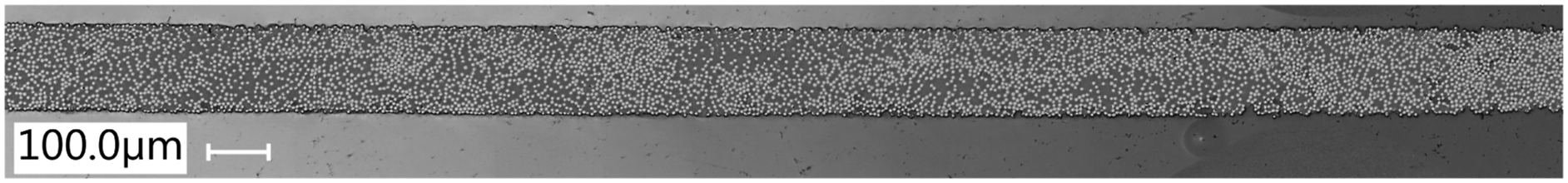
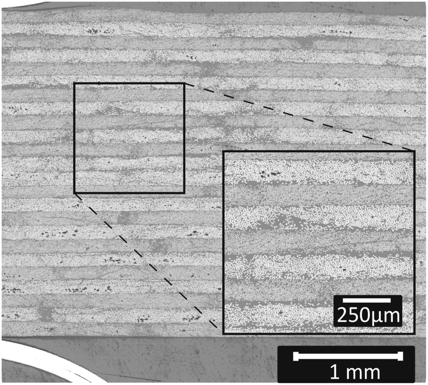
Voids in as-received tape: Intra-laminar voids may inherently be present within the as-received tape material. The amount and size of the voids in the tape vary between (different) tape manufacturing processes. To illustrate this, Figures 1(a) and (b) present the representative cross-sectional micrographs of Solvay APC (PEKK-FC) and Toray Cetex® TC1320 C/PEKK, respectively. It can be observed that APC tapes evidently have more intra-laminar voids compared to TC1320. Cross-sectional micrographs of as-received C/PEKK tapes from two different suppliers, showing (a) Solvay APC tape rough surface and (b) Toray TC1320 smooth surface. Black pixels are potential voids.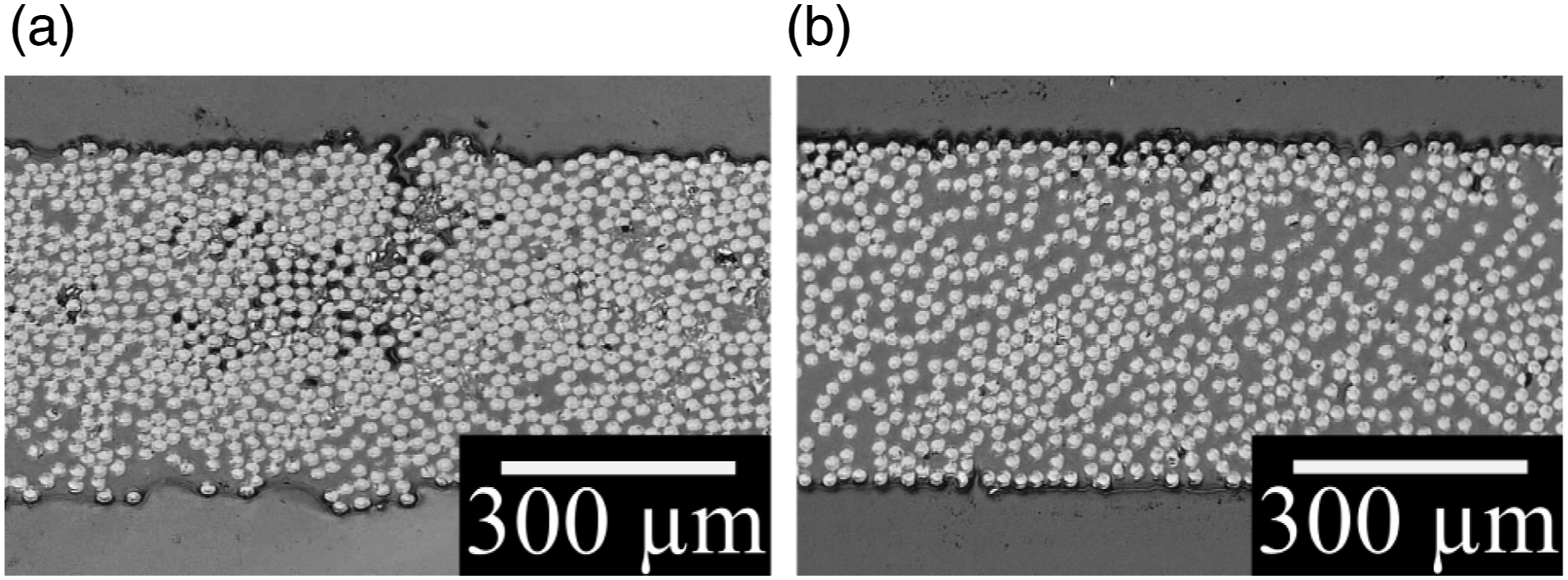
Manufacturing induced voids: Air entrapments between the tapes are common during the lay-up process. In some cases, air may be entrapped accidently through unintended variations in processing conditions, material variability, or human errors. In other cases, their presence is unavoidable, such as, for instance, in complex parts with ply-drops, gaps, and overlaps.
Void removal mechanisms
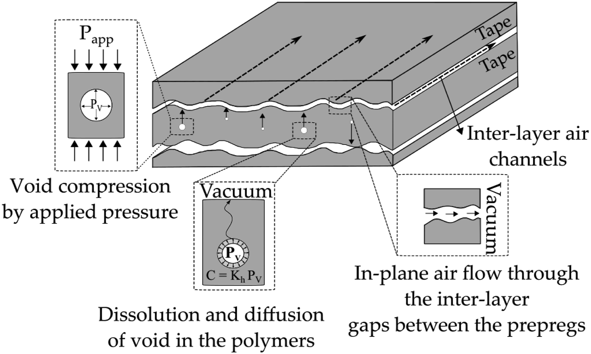
With the knowledge of void sources from the previous section, it is essential to understand the void reduction and removal mechanisms during VBO consolidation process. The generally accepted void reduction mechanisms are i. void compression, ii. dissolution and diffusion of gas molecules through the polymer matrix, and iii. in-plane air evacuation [4]. Figure 2 schematically represents these mechanisms. Void reduction and removal mechanisms during VBO consolidation, where Papp is the applied pressure, Pv is the pressure in the void, Kh is Henry’s constant and c is the gas concentration.
10
Void compression: In the current context of VBO processing, the pressures are as low as approximately 1 bar, and processing temperatures are around 400 °C for PAEKs. Assuming the voids are air pockets, the compressibility factor of air is one at the given conditions. Therefore, the air can be treated as an ideal gas, and ideal gas laws can be used to describe their state.
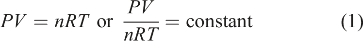
Assuming the diffusion of gas molecules into matrix material is negligible, for the current purpose, n is a constant, the ideal gas law can be simplified to
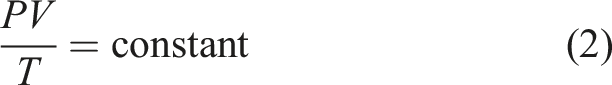
The pressure applied during autoclave processing of TPCs can easily exceed 10 bar, giving rise to a volume reduction by a factor of 10. In the case of VBO processing, with a maximum pressure of 1 bar, the ability to reduce the void volume is severely limited. Clearly, the process relies on other mechanisms to reduce the void content
Dissolution and diffusion of gas molecules from voids:
Figure 3 illustrates the process of gas dissolution and diffusion. Consider a void in a matrix material subjected to a vacuum at the surface. The solubility of gas molecules in the matrix material can be described using Henry’s law, which relates the equilibrium gas concentration in the matrix cm to the partial pressure Pg of the gas in the matrix
15
A schematic illustration of gas molecules from the void dissolving and diffusing through polymer matrix.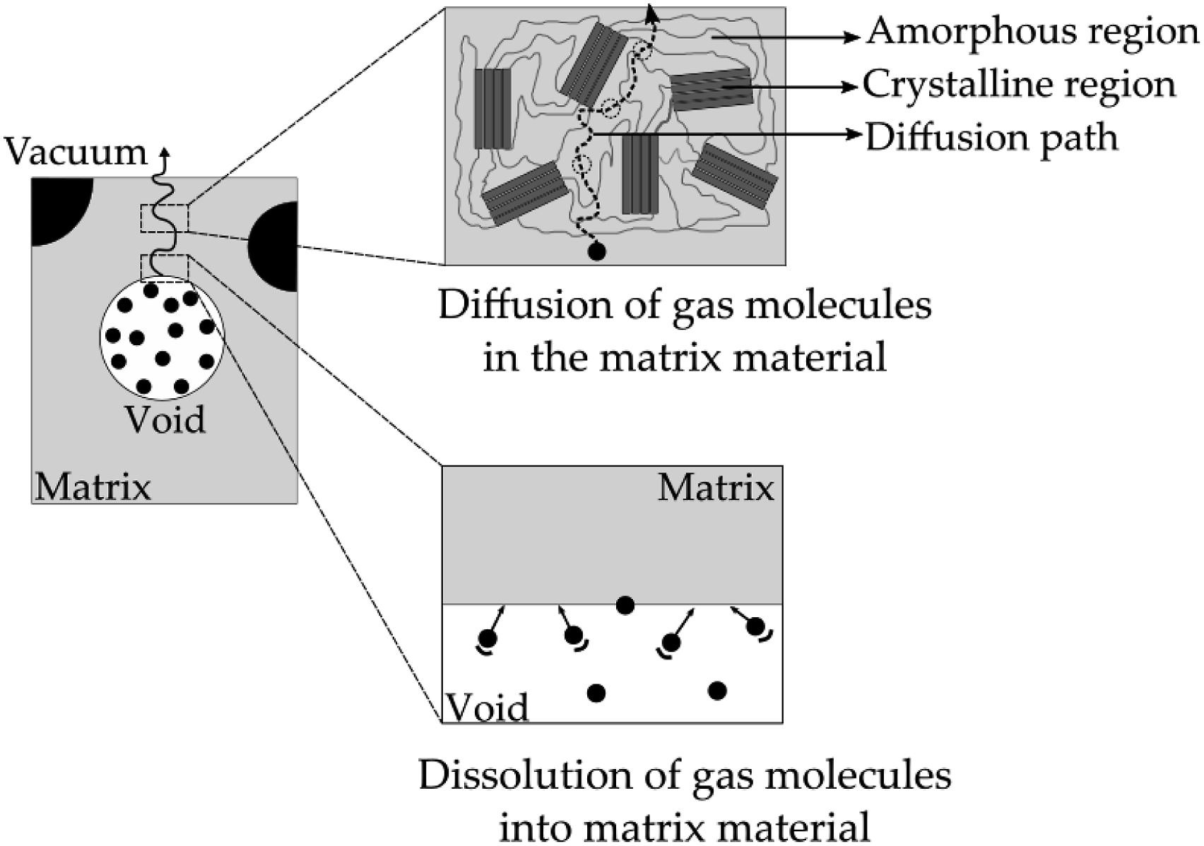

The dissolved gas molecules will increase the concentration of the gases at the void-matrix interface. With the vacuum being applied at the laminate surface, a gradient in the concentration is established. The concentration gradient drives the diffusion of the dissolved gases towards the vacuum, thereby reducing the amount of gas molecules in the voids.
Fick postulated that the rate of diffusion through a unit area is proportional to the concentration gradient, i.e
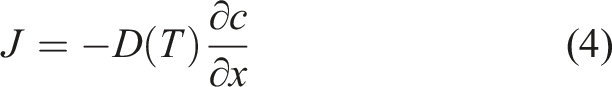
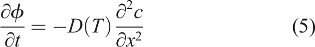
The time for diffusion depends on the solvent and the gas, which is captured by the diffusion coefficient D, the diffusion length, and the amount of entrapped gas. Further, computing diffusion time is not easy because the diffusion coefficients are generally unknown. After all, the characterization of these properties at elevated temperatures is challenging, while, in addition, the exact chemical composition of the gases to be diffused which may include volatiles from the matrix, is not clear and may differ between different tape manufacturers.
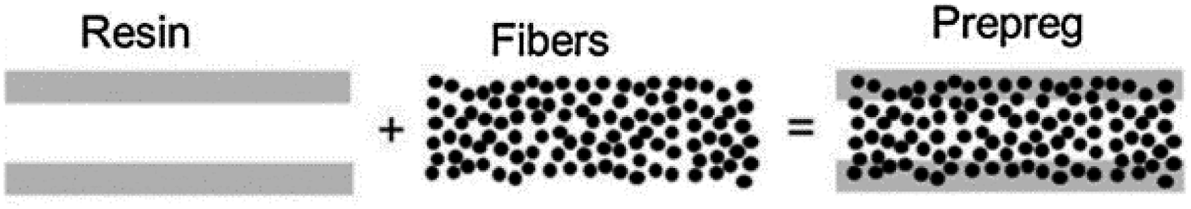
In-plane air evacuation: Under the application of vacuum, in the presence of inter-layer porous pathways, air present between the tapes can be evacuated to the perimeter of the composite part. The thermoset prepregs industry developed OoA prepregs with engineered air evacuation channels, which consist of a resin-impregnated region and an un-impregnated dry fiber region, as shown in Figure 4. The region of dry fibers acts as porous pathways for air evacuation.
16
Schematic of OoA thermoset tape.
16
Zhang et al., 17 showed that in the case of thick laminates of 72 plies, stacking of APC-2 UD AS4D/PEEK tapes resulted in inter-layer air channels due to the surface roughness of the tapes. These air channels facilitated in-plane air evacuation, resulting in void-free laminates after VBO consolidation. Thus, these authors concluded that tape surface roughness played a vital role in reducing final void content in thick TPC parts.
In summary, the main void reduction and removal mechanisms are void compression, dissolution, and diffusion of gas molecules from the voids, and in-plane air evacuation. Compression of the voids volume is impossible due to low pressures, which is typical for VBO process, while in the case of tapes with low surface roughness or for lay-ups manufactured through an automated layup process, the in-plane air evacuation may be limited. Consequently, void removal by dissolution and diffusion is assumed to be predominant in such cases. The diffusion mechanism is governed by the diffusion lengths, the amount, and the chemical composition of the gas to be diffused. Therefore, the dissolution and diffusion process will demand a longer processing time in the case of thick sections and for tapes with higher volatile contents. In this work, an experimental study is performed to understand the influence of tape material on different void removal mechanisms which dictated the VBO processing of thermoplastic composite tapes.
Experimental work
Material
UD 305 mm wide C/PEKK tape from Solvay APC (PEKK-FC) and Toray Cetex® TC1320 PEKK are considered. Both tapes consist of AS4D fibers with a reported resin content by weight of 34% and a fiber areal weight of 145 g/m2. Figures 5 and 6 present a cross-sectional micrograph of the as-received APC and TC1320 tape, respectively. Even though these tapes appear to be similar on datasheets, in reality, they are distinct in aspects such as surface roughness and fiber-matrix distribution. Cross-sectional micrograph of APC tape. Cross-sectional micrograph of TC1320 tape.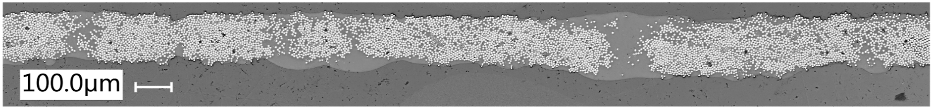
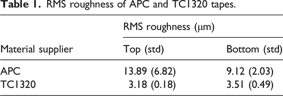
RMS roughness of APC and TC1320 tapes.
Manufacturing method
For this study, one APC and five TC1320 cross-ply, 305 mm × 305 mm laminates with varied thicknesses were manufactured using the VBO consolidation process, and a standard autoclave laminate was manufactured using both APC and TC1320 as a benchmark. Figure 7 shows a schematic of a typical bag setup used. Schematic of a typical vacuum bag set-up used.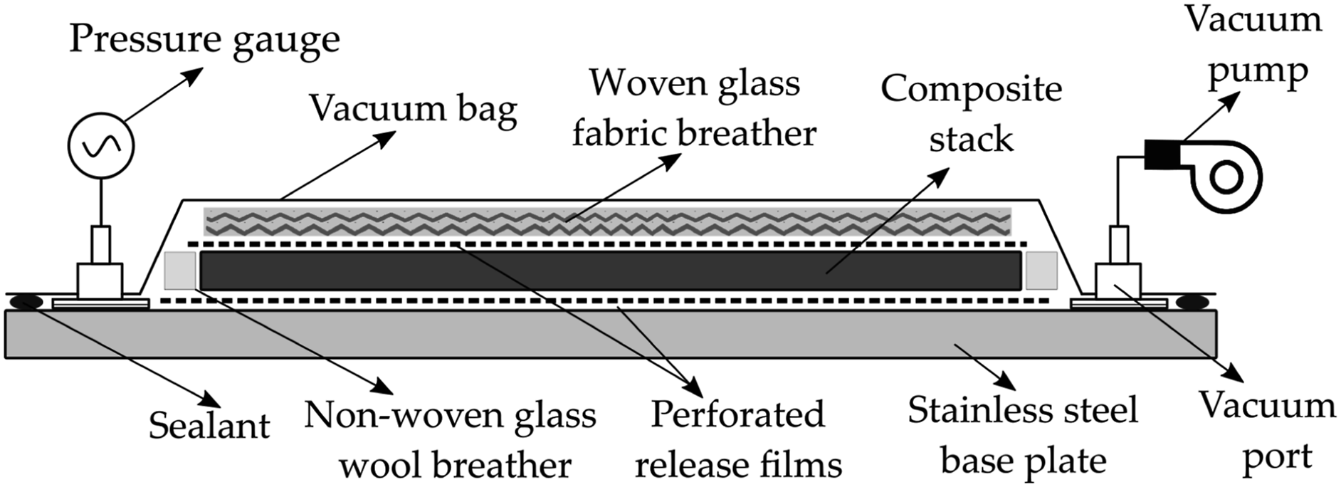
The composite stack was placed on a 600 mm × 600 mm × 10 mm steel base plate. Perforated release films UPILEX® 25S with a thickness of 25 μm were placed on the top and bottom of the composite stack to facilitate an easy release. Non-woven glass wool breather material was placed around the stack. On top of the composite stack, eight layers of woven glass fabric were used as a breather. For a couple of consolidation experiments, the bag setup was slightly modified with an additional breather on the bottom of the stack as well to enhance the diffusion process. Finally, 50 μm polyimide vacuum-bag film was placed on top and sealed to finish the bag setup.
The overview of laminates manufactured.
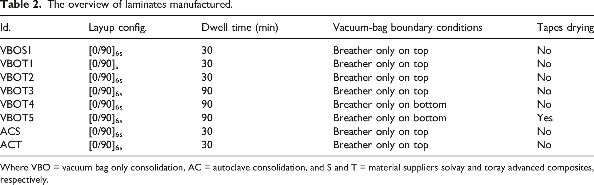
Where VBO = vacuum bag only consolidation, AC = autoclave consolidation, and S and T = material suppliers solvay and toray advanced composites, respectively.
In the case of VBOT5, the tapes were dried at 140°C for 12 h prior to VBO consolidation, whereas the other laminates were manufactured without pre-drying. For autoclave laminates, ACS and ACT, the bag configuration remained the same as in Figure 7. These laminates were consolidated in an autoclave at 7 bar pressure following the temperature cycle same as VBO process with 30 min dwell.
Consolidation quality
The consolidation quality of all manufactured laminates was characterized using ultrasonic inspection, microscopic inspection, and density measurements. The ultrasonic inspection was performed using a Sonatest RapidScan2 at a 5 MHz frequency in reflection mode, that is, employing a single-sided transducer. The main purpose was to obtain an overview of the overall consolidation quality, including its distribution over the laminates. Subsequently, 20 mm × 20 mm specimens were cut out of the areas that showed poor consolidation quality and subjected to cross-sectional microscopic inspections. Next, density measurements were performed according to ASTM D792 on five 20 mm × 20 mm samples taken from both good and bad consolidated regions of each laminate. The void content of the samples V
v
was calculated by measuring the density ρ of the samples and comparing it to the reference density ρ0 of a void-free autoclave sample.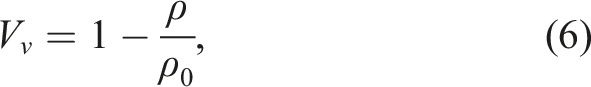
Results
Consolidation quality
Ultrasound NDT scans: The amplitude plots provide a qualitative understanding of the consolidation quality. The regions with poor consolidation dampen the signal and appear as dark regions in the figures. All consolidation cycles were repeated twice, but only one representative amplitude plot is presented here.
Figures 8 and 9 are the amplitude plots of APC [0/90]6s laminates consolidated using VBO and autoclave process, respectively. The amplitude plots showed good consolidation quality with no dark regions. Amplitude plot of VBO consolidated APC laminate. Amplitude plot of autoclave consolidated APC laminate.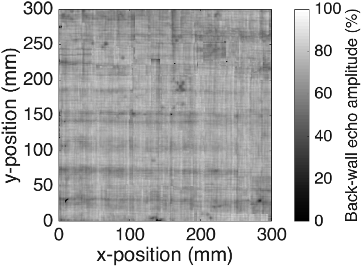
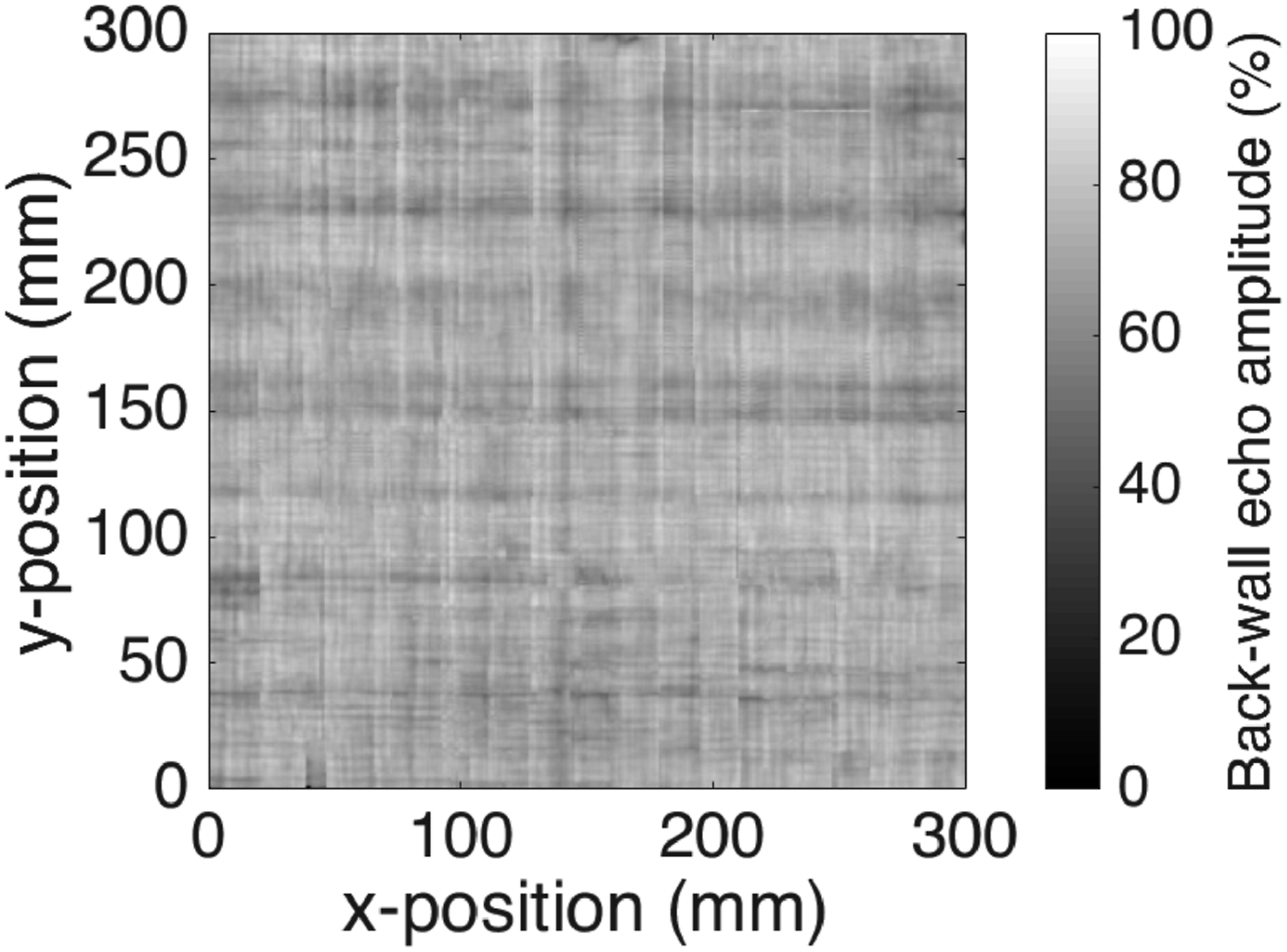
Figure 10-15 presents the amplitude plots of TC1320 laminates. Figure 10 shows the amplitude plot of VBO consolidated four-ply [0/90]s TC1320 laminate. The amplitude plot indicates good consolidation quality with no dark regions. Figure 11 presents the amplitude plot of VBO consolidated 24-ply [0/90]6s TC1320 laminate with a 30 min dwell. The laminate showed poor consolidation quality, with some lighter spots indicating good consolidation towards the edges and corners of the laminate. Figure 12 is the amplitude plot of VBO consolidated 24-ply [0/90]6s laminate with dwell time increased from 30 min to 90 min. Here, the % back-wall echo signal is improved compared to the laminate dwelled for 30 min. However, the overall consolidation quality is still not acceptable. Amplitude plot of VBO consolidated 4-ply TC1320 laminate. Amplitude plot of VBO consolidated VBOT2 laminate. Amplitude plot of VBO consolidated VBOT3 laminate. Amplitude plot of VBO consolidated VBOT4 laminate. Amplitude plot of VBO consolidated VBOT5 laminate. Amplitude plot of autoclave consolidated TC1320 laminate.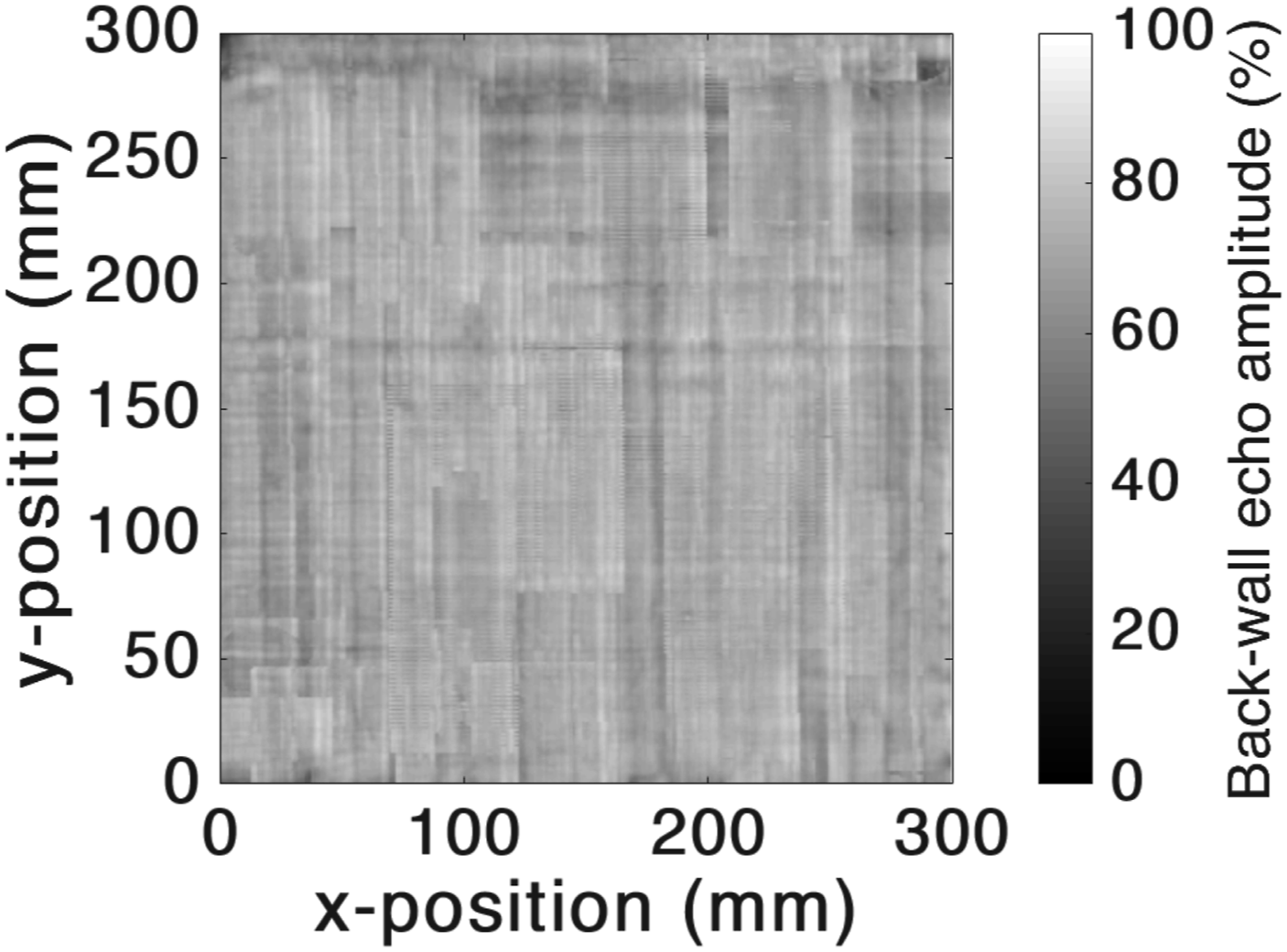
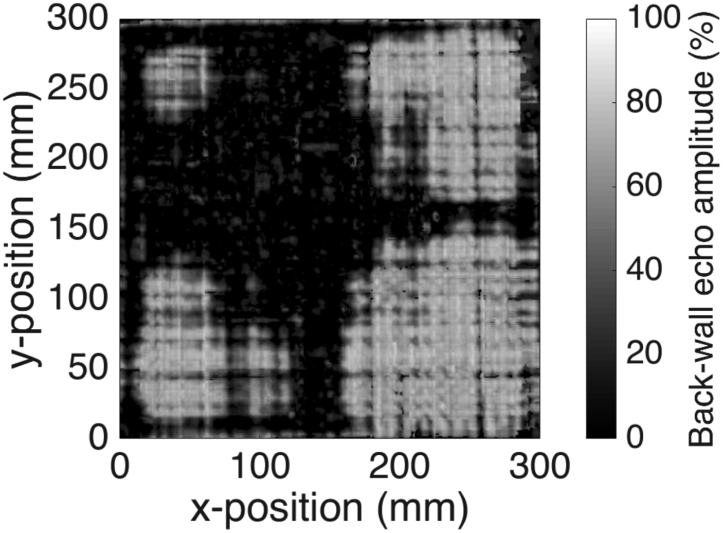
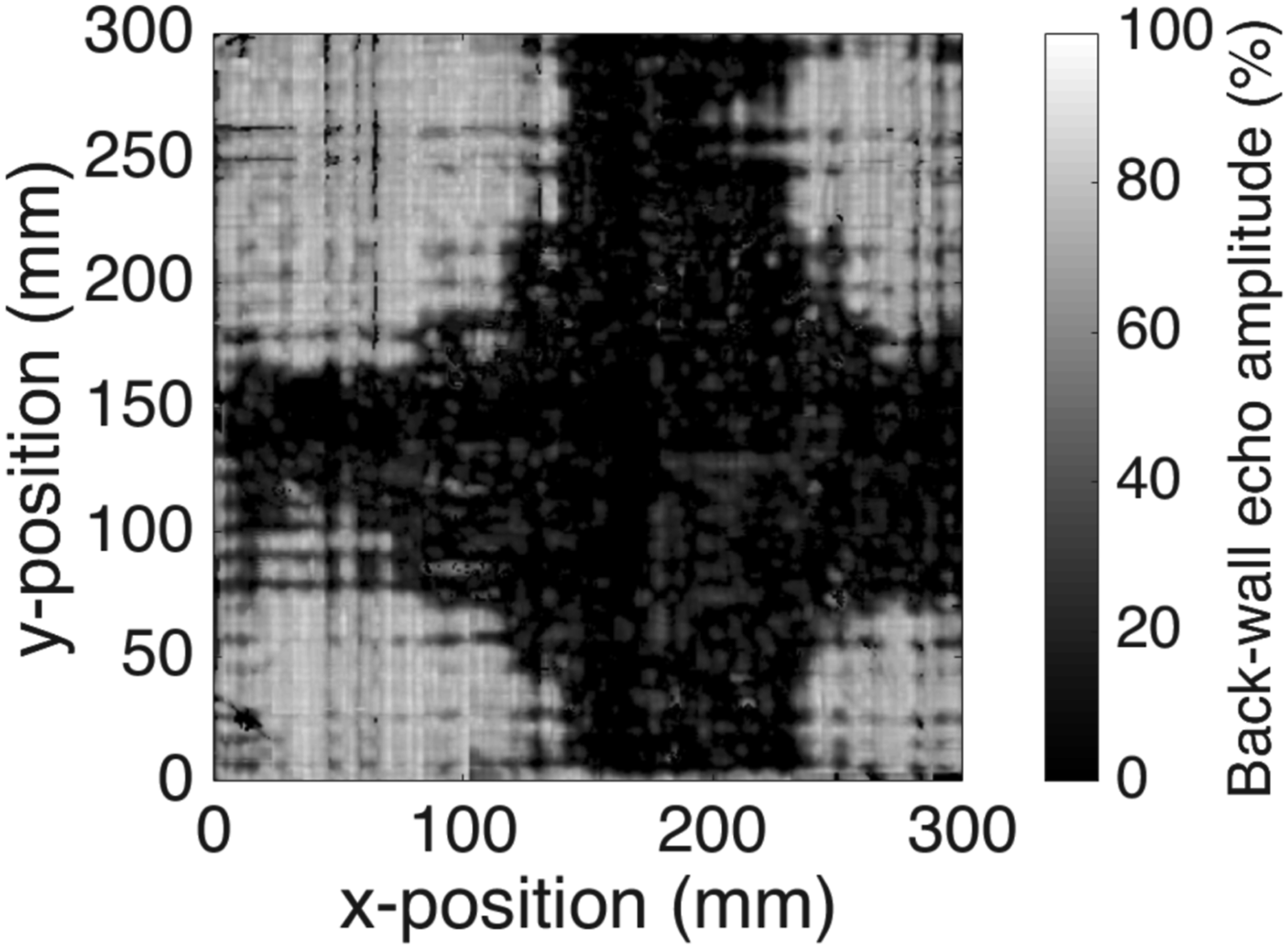
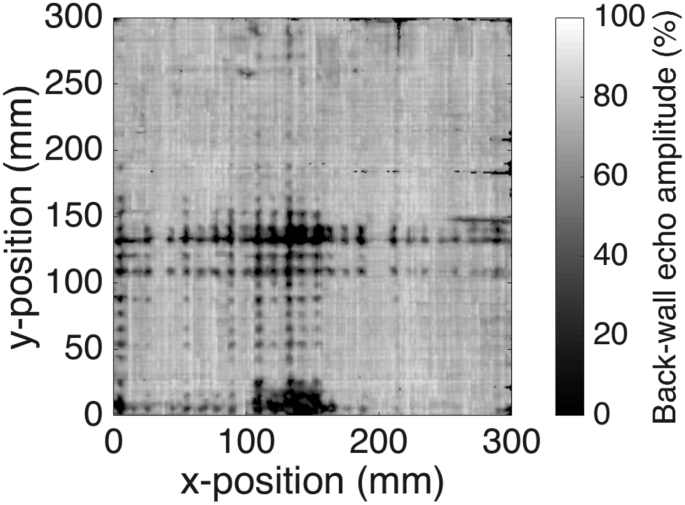
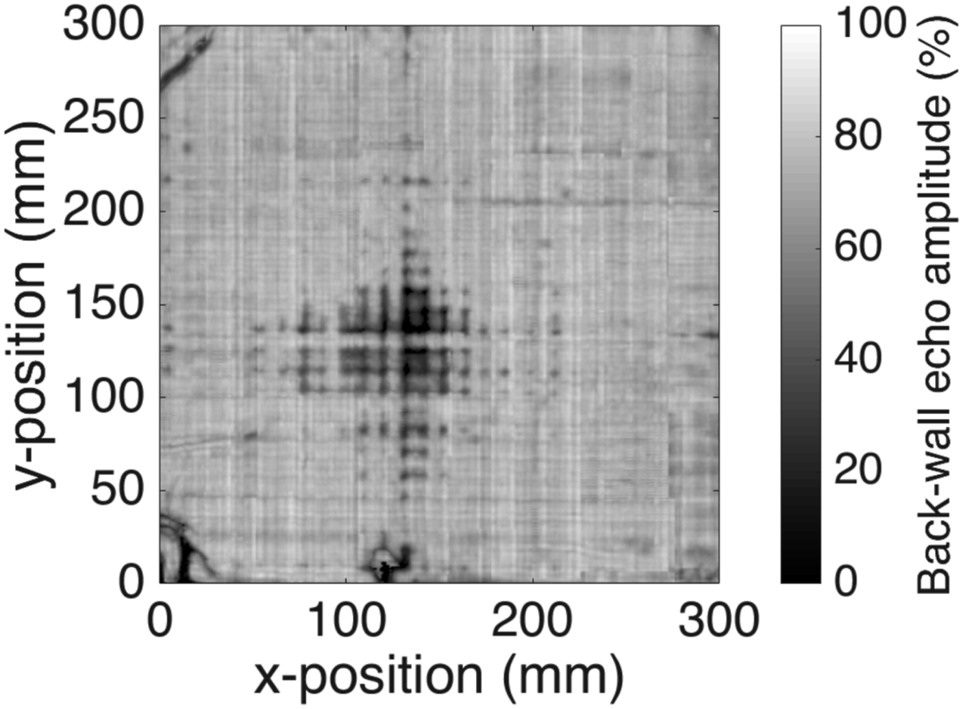
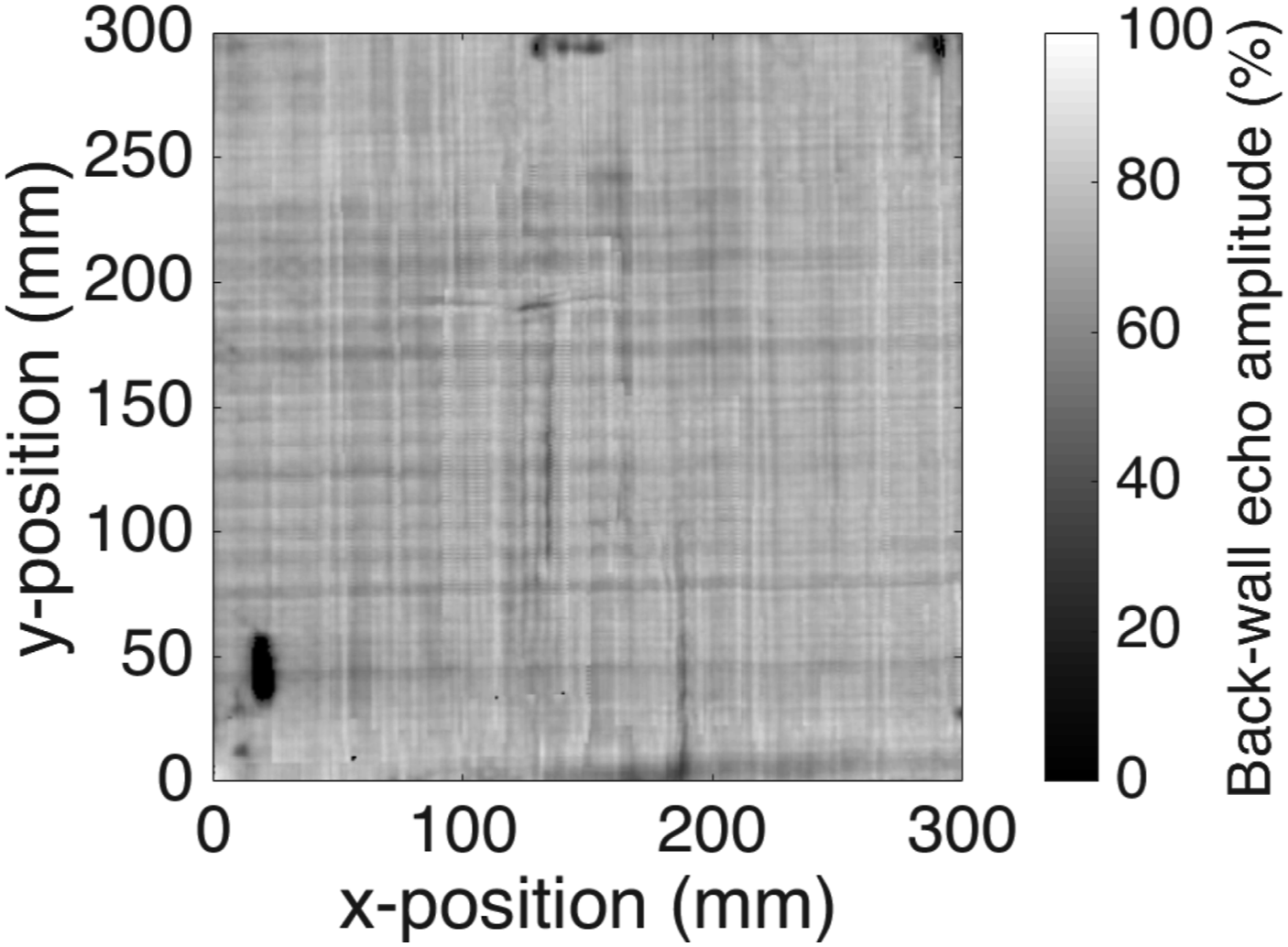
Figure 13 shows amplitude plot of the 24-ply [0/90]6s laminate with a 90 min dwell, and the breather placed on top and bottom of the laminate to enhance diffusion. The consolidation quality has significantly improved compared to the laminate with 30 min dwell.
Figure 14 presents the amplitude plot of the 24-ply [0/90]6s laminate where the tapes are pre-dried for 12 h at 140°C, and VBO consolidated with 90 min dwell, and the breather placed on top and bottom of the laminate for a better concentration gradient. A significant improvement in the consolidation quality was observed, with only a small dark region at the center of the laminate.
Finally, Figure 15 is the amplitude plot of the benchmark autoclave consolidated 24-ply [0/90]6s laminate. The consolidation quality was excellent, with no relevant dark regions on the amplitude plot except for a small dark spot in the lower left corner where the thermocouple was placed during processing.
Cross-section micrographic analysis: The amplitude plots in the previous section provided a qualitative overview of the consolidation quality. In this section, the micrographs of the laminates are presented, which will give more detailed information on the type and the location of voids. Three micrographs were made from each laminate, and one representative micrograph is presented here. Further, micrographic specimens were cut at an angle rather than 90° to the x-z plane, with z being the out-of-the-plane direction to avoid fiber breakage along the cutting direction.
Figures 16 and 17 present the cross-sectional micrographs of an APC [0/90]6s laminate consolidated using VBO and autoclave, respectively. The micrographs showed good consolidation quality with no presence of voids. Cross-sectional micrograph of VBO consolidated APC laminate. Cross-sectional micrograph of autoclave consolidated APC laminate.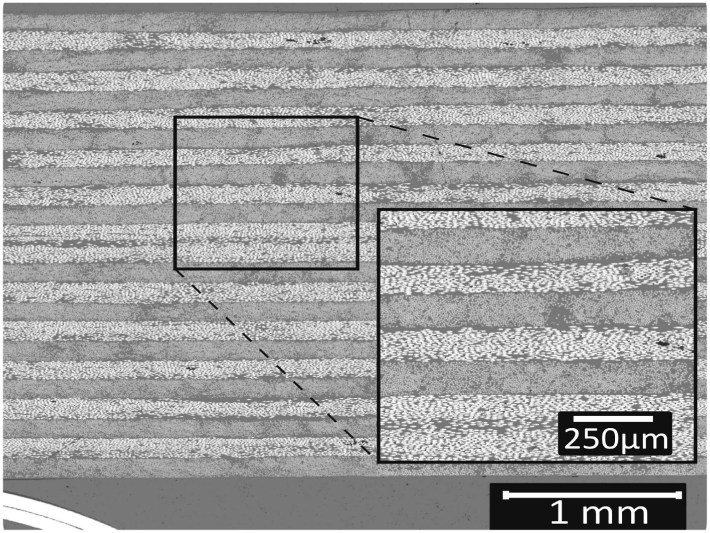
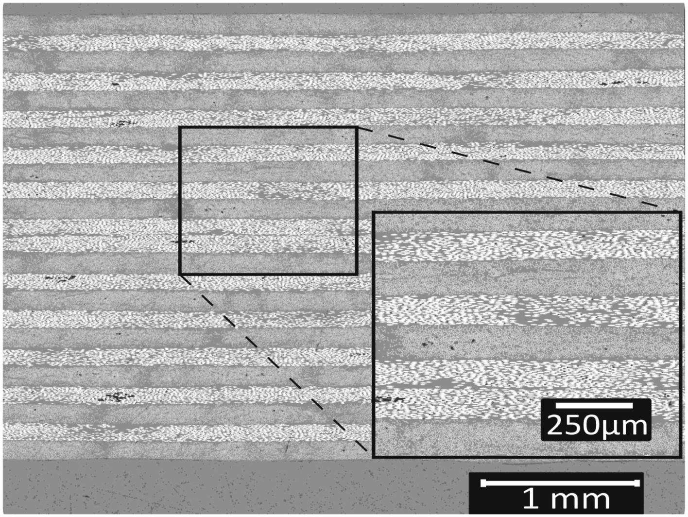
Figure 18 shows the cross-sectional micrograph of the four-ply [0/90]s TC1320 VBO consolidated laminate. The amplitude plot indicated good consolidation and, as expected, the micrographs also showed good consolidation without voids. Cross-sectional micrograph of VBO consolidated 4-ply TC1320 laminate.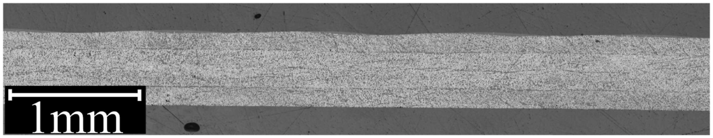
Figure 19 presents the cross-sectional micrograph of the 24-ply [0/90]6s TC1320 VBO consolidated laminate with 30 min dwell. The cross-sectional micrograph shows the presence of voids distributed along the thickness direction, with a major concentration of voids at the midsection of the laminate. Figure 20 presents the cross-sectional micrograph of the 24-ply [0/90]6s TC1320 VBO consolidated laminate with an extended dwell time from 30 min to 90 min. This micrograph shows a slight improvement compared to the laminate with 30 min dwell. The voids in the laminate were more confined to the laminate’s midplane, while the outer four to five plies did not have any voids. Cross-sectional micrograph of VBO consolidated VBOT2 laminate. Cross-sectional micrograph of VBO consolidated VBOT3 laminate.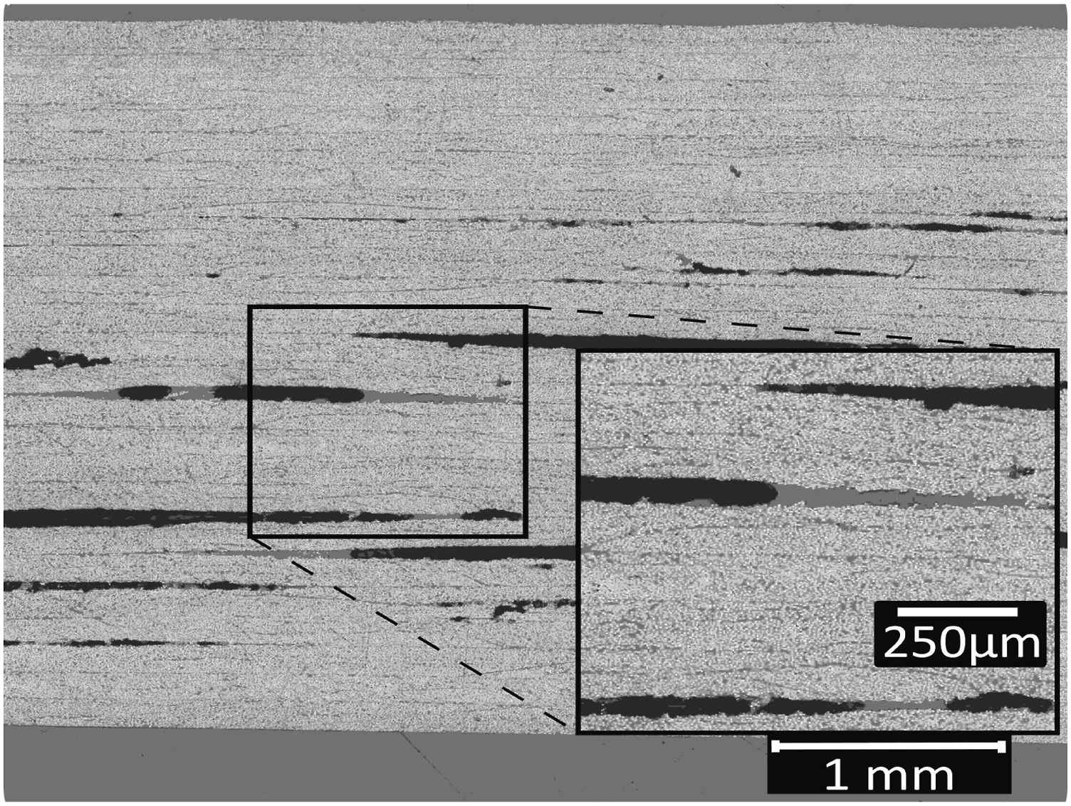
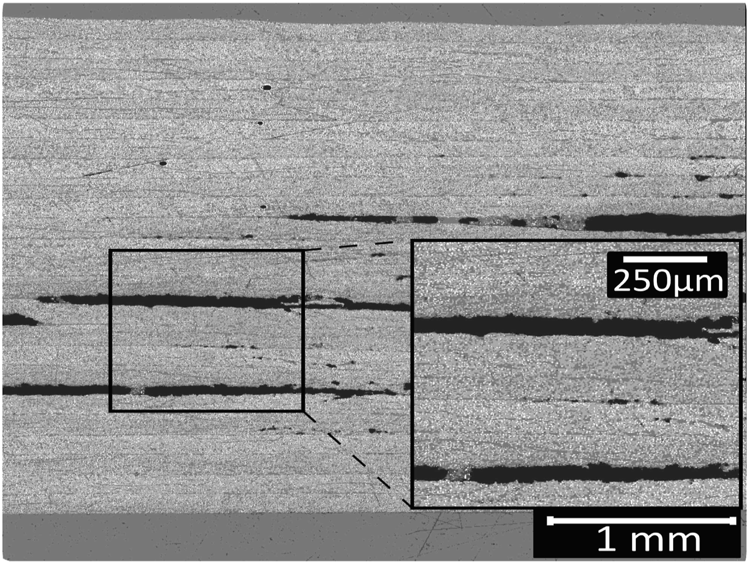
Figure 21 presents a cross-sectional micrograph of 24-ply [0/90]6s TC1320 VBO consolidated laminate with 90 min dwell, and the breather placed both on top and bottom of the laminate during the consolidation. A much lower void content is observed compared to having a breather only on the top. Cross-sectional micrograph of VBO consolidated VBOT4 laminate.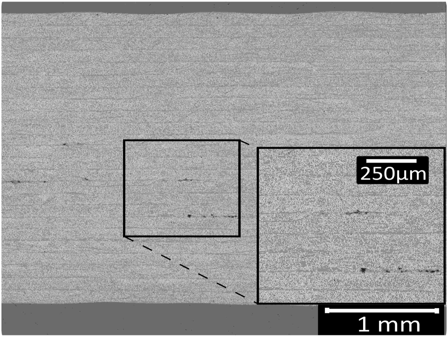
Figure 22 shows the cross-sectional micrograph of the 24-ply [0/90]6s TC1320 VBO consolidated laminate with tapes dried at 140 °CC for 12 h before the consolidation process. The micrograph of the laminate showed the least voids compared to other laminates. Cross-sectional micrograph of VBO consolidated VBOT5 laminate.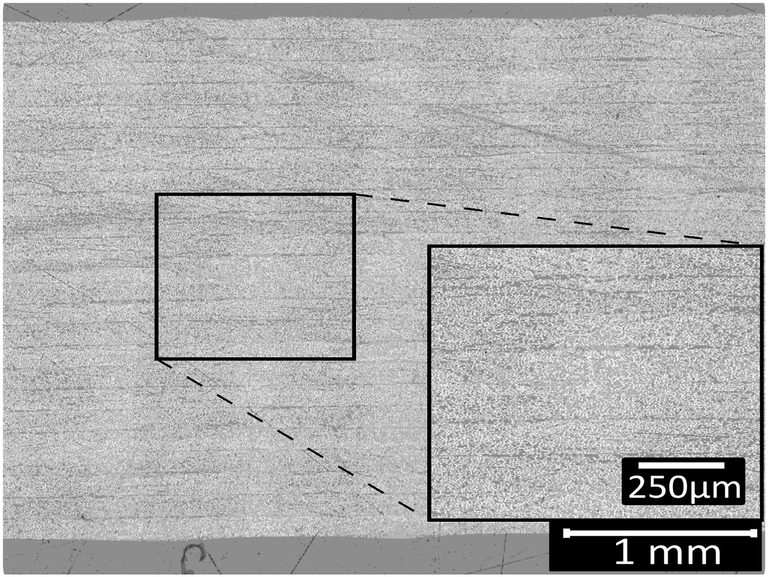
Finally, Figure 23 shows a micrograph of the 24-ply [0/90]6s autoclave consolidated TC1320 laminate. The consolidation quality was good, with no visible voids. Cross-sectional of autoclave consolidated TC1320 laminate.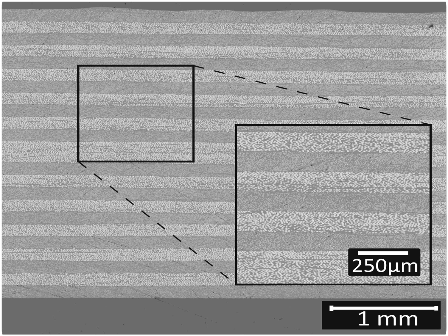
Density measurements: The void content based on the density of the laminates after the consolidation is presented in Figure 24. The presented data represent the upper limit of the void content as the samples are chosen from poor consolidation regions. The cross-sectional micrographs confirmed that the autoclave consolidated laminate showed no presence of voids. Therefore, these laminates are considered the void-free reference, from which ρ0 is determined. Void content of consolidated laminated based on density measurement.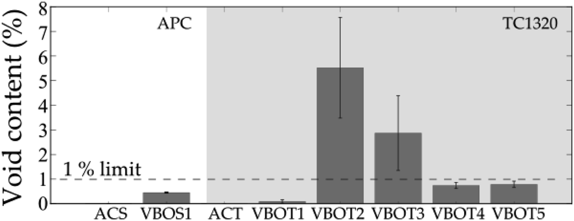
The APC 24-ply VBO consolidated laminates showed the lowest void content, whereas the TC1320 24-ply VBO-consolidated laminate with 30 min dwell time showed the highest void content. However, by increasing the dwell time from 30 to 90 min and using a breather on top and bottom, the void content of 24-ply TC1320 laminate can be reduced to less than 1%.
In summary, APC tapes resulted in good VBO consolidation quality with less than 0.5% voids in a short dwell time of 30 min. TC1320 laminates showed varied consolidation quality under different processing conditions. Firstly, four-ply TC1320 laminates showed a void-free consolidation quality. However, when the laminates’ thickness was increased from four plies to 24 plies, with a 30 min dwell time, the consolidation quality was reduced with a void content of around 5.5%. Further, increasing the dwell time from 30 min to 90 min and using a breather on top and bottom of the composite stack in the vacuum bag resulted in improved consolidation quality with a void content below 1% and acceptable NDI results.
Discussion
Void removal mechanisms
Two kinds of void removal mechanisms are possible during VBO consolidation. These are void removal by in-plane air evacuation, and dissolution and diffusion of gas molecules from the voids primarily through the thickness of the laminate. Tape characteristics, other than the type and fraction of constituents, appear to have a significant influence on the final void content in the laminates and the mechanisms leading to this final state of consolidation. The following sections provide a detailed explanation of the role of such tape characteristics on the void removal mechanisms.
APC tapes: Figure 25 represents the possible void reduction and removal mechanism in APC tapes. It can be observed that due to stacking the rough tapes on top of each other, inter-layer porous channels are formed, and these channels assist in-plane air evacuation of entrapped gases. Volatiles diffuse to the tape’s surface, and then they can be evacuated via the in-plane channels. Possible air removal mechanism during VBO processing of APC tapes.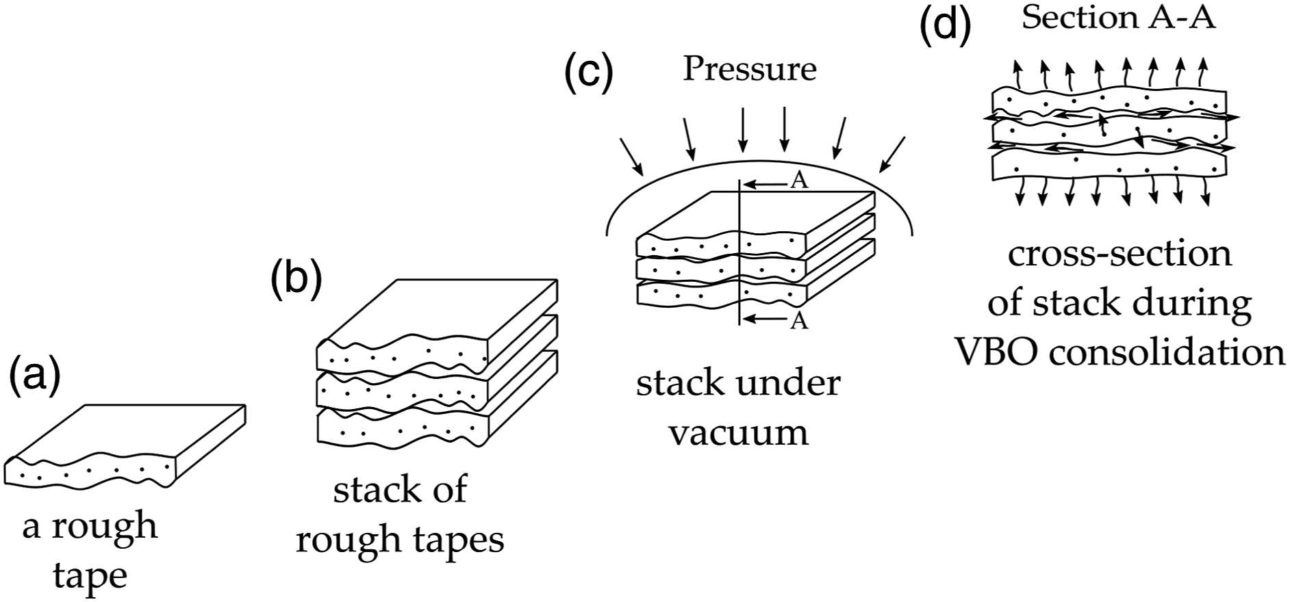
However, in the case of automated fiber-placed preforms, the tapes are melted to stick, and the benefit of in-plane air evacuation is lost. Thus, it is essential to understand the consequence of limited in-plane air evacuation on the consolidation quality of APC tapes. Therefore, additional consolidation experiments were performed by limiting in-plane air evacuation. 10 For this purpose, the lack of in-plane air evacuation was simulated by blocking the laminate’s edges with aluminum foil and Kapton tapes during VBO consolidation process and thus essentially limiting the void removal mechanisms to diffusion only. Further, the lay-up configuration, bagging setup, and consolidation cycle were equal to VBOS1.
Figures 26 and 27 present the amplitude plot from the ultrasound scan and the cross-sectional micrograph, respectively. Amplitude plot of VBO consolidated of APC tape with edges sealed. Cross-sectional micrograph of VBO consolidated of APC tape with edges sealed.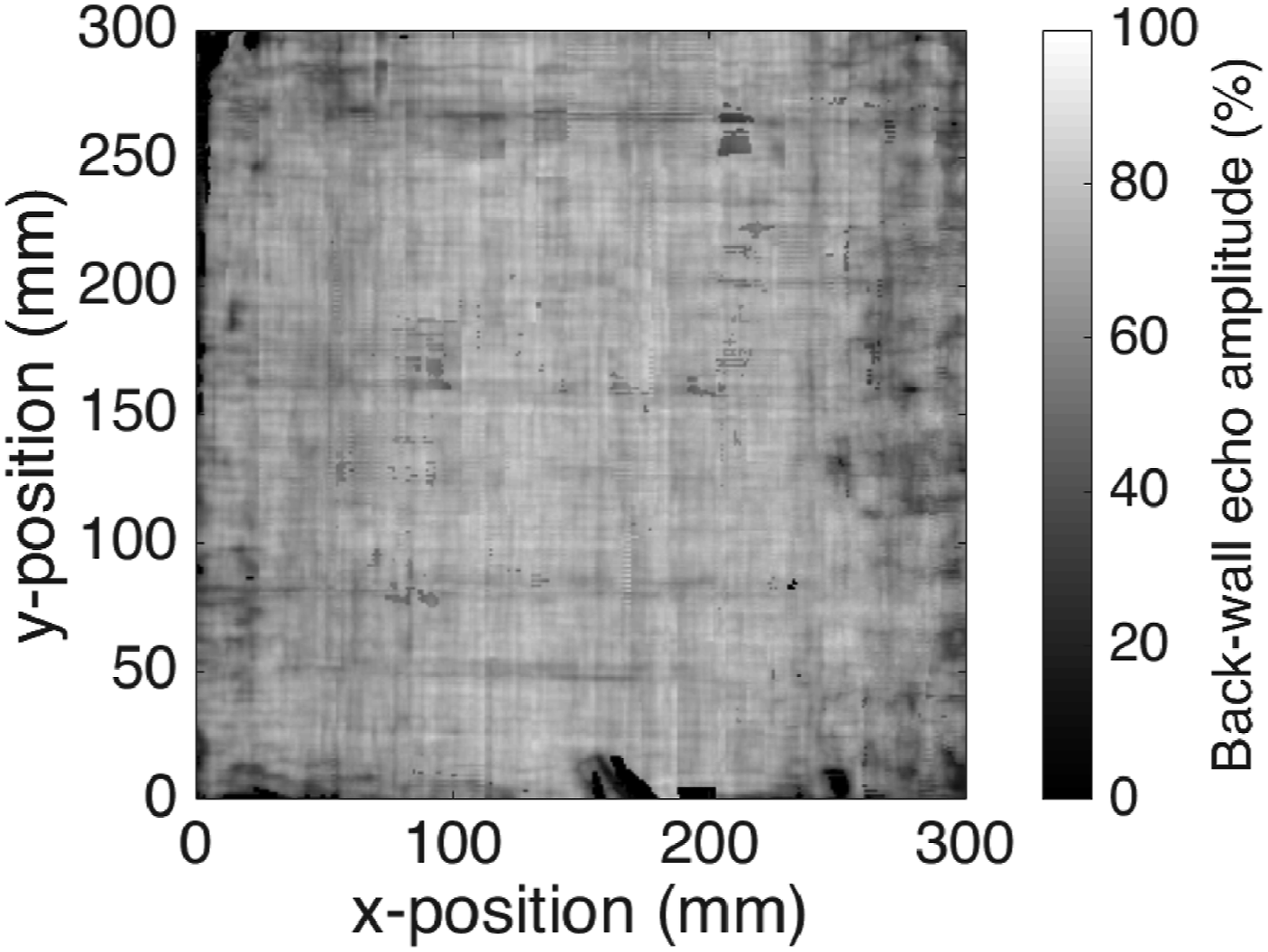
The amplitude plot and the cross-sectional micrographs indicate that even after restricting in-plane air evacuation in tapes, good consolidation quality of a 24-ply APC laminate could be achieved with a dwell time of 30 min proving that the void removal by diffusion was dominant in the absence of in-plane air evacuation.
TC1320 tapes: Figure 28 represents the possible void reduction mechanism in TC1320 tapes. In the case of TC1320, as the tapes are smooth, the inter-layer porous channels are smaller, thereby limiting the void removal to diffusion alone. Possible air removal mechanism during VBO processing of TC1320 tapes.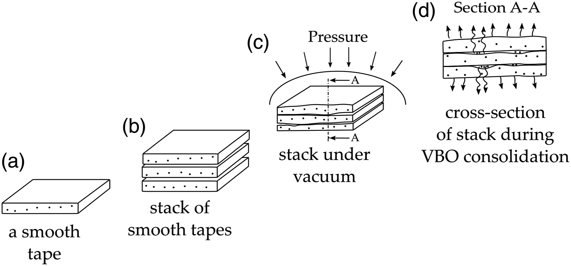
The consolidation experiments of TC1320 supported this hypothesis. For example, reducing the diffusion length, in this case, the thickness of the laminate to four plies, or increasing the diffusion time, in this case, dwell time to 90 min, resulted in acceptable consolidation.
The experiments with the sealed laminate edges illustrate clear differences between the two material systems. Here, the void removal was limited to dissolution and diffusion, as the porous pathways required for in-plane flow were blocked. However, the time for achieving the void-free consolidation varied significantly between the two material systems. For a 24-ply APC laminate, 30 min dwell was sufficient, whereas in the case of TC1320, a three times longer dwell was needed. The cause for this difference may be twofold. First, the diffusion coefficient may be higher in the case of APC tape compared to TC1320. Although both tapes comprise a PEKK matrix, the exact formulation may differ. Second, the volume of gas that needs to be removed may not be the same. It is essential to realize that these gases include not only the entrapped air, both in the as-received tape and between the tapes but also volatiles released from the tape during the consolidation process. To address the latter, ThermoGravimetric Analysis (TGA) was used to measure the mass of the volatiles in the tape.
Evaporation of volatiles
Volatiles can be the solvents in the tape from the manufacturing or the moisture absorbed by the polymer matrix prior to processing. During the processing of TPCs, these volatiles may evaporate and can be a significant source of voids during the VBO consolidation process. TGA can provide quantitative information on the amount of volatiles.
18
Figure 29 presents the weight change curves of both APC and TC1320 tape material. The primary y-axis represents the change in mass in %, while the x-axis represents time (min). The secondary y-axis represents the temperature in °C. TGA, mass change plot of APC and TC1320 tapes.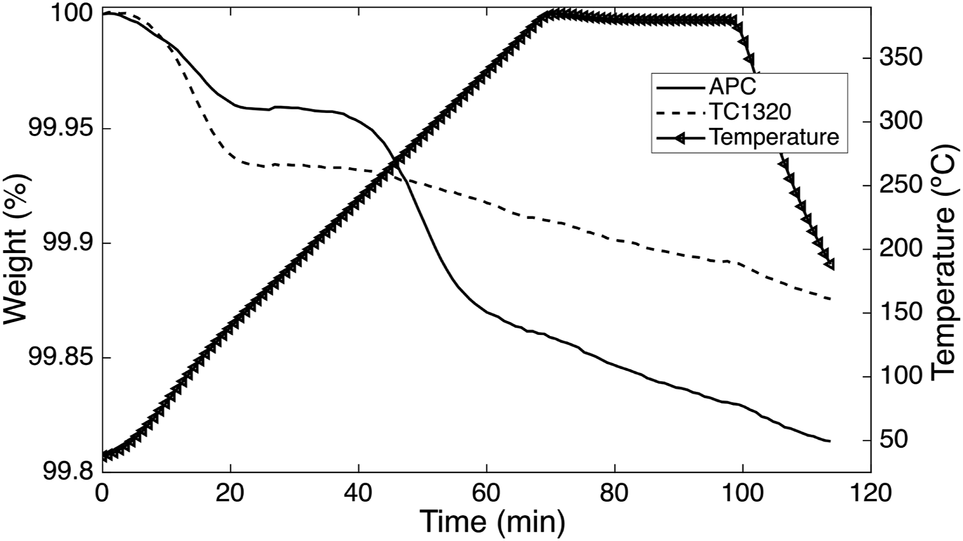
As soon as the tapes are heated, both tapes start to lose weight. The initial drop in weight can be associated with, primarily, water molecules or moisture evaporation. The APC material shows a drop of 0.04% in mass until 150°C, after which the mass temporarily stabilizes. A second, steeper mass loss trend is observed in the range of 230–240°C until the melt temperature of 330°C with a drop of around 0.14% of the mass. Once the melt is reached, the mass loss is more linear in time. TC1320 showed a mass loss of around 0.07% from the start of the heating phase until 150°C and showed a negligible mass change up to 250°C. Later, a linear change in mass was observed similar to APC material. The overall mass loss during a typical VBO cycle in APC and TC1320 tapes are 0.19% and 0.12%, respectively.
The TGA measurements showed that APC tapes have approximately 1.5 times or more volatiles by weight than TC1320 tapes. However, the time for achieving a void-free state in the case of APC tapes was three times faster than TC1320. Furthermore, TGA measurements only provided the weight of the diffusing species, whereas the actual volume of the gases is yet undetermined, as the chemical composition and corresponding molecular weight distribution are unknown.
Conclusion
This paper presented a study on VBO consolidation of two commercially available high-performance C/PEKK thermoplastic composite tapes, namely Solvay APC (PEKK-FC) and Toray Cetex® TC1320. The tape materials look similar on datasheets but differ in terms of surface morphology, fiber matrix distribution, and initial void content. In addition, TGA experiments demonstrated that the mass of the volatiles that evaporates during consolidation is different for the two tapes as well. Both tape materials were successfully consolidated using a vacuum-bag-only process in a convection oven. Additional experiments with sealed edges were performed to demonstrate that through-thickness diffusion can be sufficient to achieve good consolidation quality. One of the tape materials, however, demanded longer processing times, as well as an additional breather on the bottom surface of the laminate to enhance the diffusion process. The difference in the times required for consolidation may be due to the following. Firstly, the diffusion coefficients may be different for the two tapes. Although the matrix material in both tapes is PEKK, the exact formulation is unknown. Secondly, the amount and composition of the gas that needs to diffuse through the matrix may be different as well. The gas comprises not only the entrapped air but also the volatiles that evaporate during the process, which may differ in composition as well as amounts for the two materials. At present, it is unclear whether one of these possible causes has a dominant effect (if any).
The first recommendation for future work is to characterize the volume and composition of the volatiles that evaporate from the tape material during VBO processing. Possibly, thermogravimetric analysis combined with residual gas analysis on the tape material can help to identify the type and volume of the volatiles. Second, the diffusion coefficients of gases through the polymer could be evaluated experimentally, although this is far from straightforward, given the high temperatures involved. The diffusion coefficients, in combination with an estimation of the amount of gas that needs to be removed, can be used to define initial processing windows for VBO consolidation of high-end thermoplastic composites. Lastly, the presented results successfully demonstrated that void-free VBO consolidation of 24-ply thick laminates is possible by means of through-thickness diffusion. Therefore, the processing windows identified in the current work can possibly be extrapolated to larger structures. This would potentially open up a two-step processing strategy for integral manufacturing of large TPC components/substructures, where AFP is used to lay down large parts, followed by an affordable VBO post-processing step to ensure good consolidation. Given the presented results, it seems warranted to explore further in this direction.
Footnotes
Declaration of conflicting interests
The author(s) declared no potential conflicts of interest with respect to the research, authorship, and/or publication of this article.
Funding
The author(s) received no financial support for the research, authorship, and/or publication of this article.