
Abstract
In the interest of developing a comprehensive understanding of the drilling process using the hole saw tool, this article aims to build a three-dimensional (3D) micromechanical model representing the orthogonal cutting of CFRP using one tooth of the hole saw tool. For this purpose, a finite element model is developed using Abaqus Explicit code. The influence of various drilling parameters like rake angle, inclination angle and cutting-edge radius on the drilling quality is explored. Especially, chip formation mechanisms, cutting force and lateral damage are analyzed. Through finite element simulations and computational analyses, it is found that these outputs results are highly influenced by drilling parameters. When the fiber orientation angle is set to 0°, increasing the rake angle results in a change in the chip formation mechanism from buckling to bending. In contrast, with a fiber orientation angle of 90°, bending and shear governs the chip formation process, irrespective of the rake angle. In both cases, whether the fiber orientation angle is 0° or 90°, chips tend to fragment more favorably with increasing the inclination angle. Regarding the cutting-edge radius, when the fiber orientation angle is 0°, an increase in the cutting-edge radius leads to a transition in the chip-forming mechanism from buckling to bending. However, for a fiber orientation angle of 90°, the chip formation remains governed by bending even as the cutting-edge radius changes. Decreasing the rake angle, the inclination angle, and the cutting-edge radius contribute to a reduction of the cutting force. As the inclination angle and the cutting-edge radius increase, the lateral damage increases, while the rake angle has showed a negligible impact on the damage. These results provide a guidance on the appropriate hole saw tool parameters for a good drilling quality namely, a rake angle of 20°, an inclination angle of 5° and a cutting-edge radius of 0.03 mm.
Introduction
The aerospace industry has been witnessing a remarkable surge in the usage of advanced composite materials, revolutionizing the design and the construction of aircraft components. Composites offer exceptional strength-to-weight ratios, corrosion resistance, and improved mechanical properties, making them an ideal choice for aircraft structures. 1 However, as the demand of composite components raised, engineers and researchers have faced a new set of challenges, particularly in the drilling process. The drilling of composites required precision, and defects observed during this process, such as delamination, burrs, tearing etc., 2 could lead to catastrophic consequences. Therefore, the aerospace industry and the research have been tirelessly exploring novel drilling approaches and technologies that ensure reliable, efficient, and damage-free fabrication of composite materials. 3 In the literature, a considerable amount of work is dedicated to meticulous experimental studies,4–8 while substantial research is dedicated to delving into the domain of numerical modeling to improve drilling quality. Numerical modeling of composite materials falls into two categories: macromechanical modeling 9,10 and micromechanical modeling.11,12 In the case of macromechanical analysis, the composite material is treated as an equivalent homogeneous material. This assumption is adopted to alleviate complexities in machining simulation, at the expense of achieving slightly less precise outcomes. Within this framework, Isbilir et al. 13 made a comparison study between the step drill of different stage ratio and the twist drill during the drilling of carbon fiber reinforced polymer (CFRP) using the finite element method. They found that the step drill exhibits lower torque, thrust forces and damage compared to the twist drill under similar drilling process conditions, including the feed rate and the speed. Joshi et al. 14 carried out numerical drilling tests on glass fiber reinforced polymer (GFRP) composite using a twist drill. They have shown that the feed force increases with the increase of cutting speed, while a small variation of this force with the drill point angle was observed. Based on orthogonal cutting of CFRP, Zenia et al. 15 investigated the influence of the fiber orientation on chip formation mechanisms, cutting forces and damage using a new material behavior. They discovered that the fiber orientation significantly influences all mentioned outputs. Moreover, their demonstration revealed that the 90° fiber orientation resulted in the most significant damage. Xu et al. 16 analyzed the chip removal process and the surface quality as a function of the fiber orientation and the feed rate during the orthogonal cutting of CFRP/Ti6Al4. They found that to minimize the cutting force and the extent of damage caused by machining, high cutting speeds, reduced feed rates and smaller fiber orientations were recommended.
A considerable amount of recent research that addresses the simulation of cutting processes of composite materials has been dedicated to the exploration of a two-dimensional (2D) or three dimensional (3D) orthogonal cutting model based on a micromechanical approach. In this approach, each component of the composite structure, fibers, matrix, and fiber/matrix interfaces, is modeled separately. This provides precise information on the interaction between the fiber and the matrix. In this context, Rao et al. 17 developed a 2D micromechanical model to simulate the orthogonal cutting of CFRP and GFRP. The conclusions drawn by these authors revealed that chip formation mechanisms were significantly influenced by the fiber orientation angle and the nature of reinforcements. Indeed, for a fiber orientation of 90°, the fiber rupture is driven by bending and crushing mechanisms for CFRP, while bending fracture predominates for GFRP. Cheng et al. 18 developed a 3D micro scale model involving thermal-mechanical coupling for the cutting of CFRP. They found that the cutting force surpasses the thrust force irrespective of the fiber orientation. Furthermore, when fiber orientations were between 0° and 90°, fiber breakage is shear-induced. However, for fiber orientations exceeding 90°, fiber failure primarily arises from fracture induced by bending. Liu et al. 19 formulated a three-dimensional finite element model for the purpose of simulating the orthogonal cutting of CFRP. The effect of the cutting speed and fiber orientations on the surface quality were analyzed using micromechanical model. They showed that the lower the cutting speed, the greater the surface defects due to bending-induced fiber breakage. Tang et al. 20 investigated the effect of the fiber orientation on the hole delamination and the chip formation using 3D micromechanical modeling for orthogonal cutting of CFRP.
They found that for fiber orientations of 0°, 45°, and 90°, fibers encircling the hole entrance have showed susceptibility to fracture via diverse failure modes, resulting in the formation of distinct chip types. Consequently, the likelihood of delamination is minimal in these cases. Conversely, the 135° fiber orientation represents a susceptible point where the peel-up damage attains its most severe manifestation.
Although extensive research has been conducted in the area of drilling composites, a significant gap remains conspicuous: the absence of comprehensive micromechanical modeling for hole saw tool. This conspicuous gap in the existing body of knowledge underscores the central emphasis of this work. The micromechanical modeling of the drilling operation, allowing to describe the behavior of the different components, is almost challenging since it requires a huge computing time with a considerable memory space and consequently, a simplified elementary study is necessary.
The goal of this work is to create a 3D micromechanical model that depicts the orthogonal cutting of CFRP using a single tooth from a new industrial-proposed tool design named hole saw tool. This endeavor aims to understand mechanisms involved in this procedure and identify the appropriate hole saw tool geometry to achieve good drilling quality.
For this purpose, a 3D micromechanical model simulating the orthogonal cutting of CFRP composite by a hole saw tooth is set up upon Abaqus/explicit software. The effect of various factors, namely the rake angle, the inclination angle, and the cutting-edge radius on the drilling quality is investigated. Chip formation mechanisms, cutting force and workpiece damage are analyzed, for different fibers orientations angles.
Transition from Complete to Simplified Model
To conduct a micromechanical study, a model involving a single tooth, leading to the case of 3D orthogonal cutting is selected. Figure 1(a) presents the hole-saw tool during the drilling operation of composite plates. Figure 1(b) shows a close-up of a tooth of the hole saw tool while drilling the UD-CFRP in the steady-state condition. The hole saw tool features a 10.5 mm diameter (D), composed of several teeth (12 teeth) with thin thicknesses of about 0.5 mm. These teeth have specific angles, including a 0° rake angle, a 5° clearance angle, and a 0.01 mm cutting-edge radius. It’s important to emphasize that these teeth are intentionally staggered radially to enhance the removal of chips. This tool serves to reduce the thrust force by mitigating the impact of the helical drill core. The groove in the workpiece of the Figure 1(b) represents the trace of the previous tooth, which is offset by 0.25 mm in relation with the following tooth. (a) transition from compete to simplified model and (b) close-up of a tooth of the hole saw tool and (c) Schematic representation of the fiber arrangement in the matrix.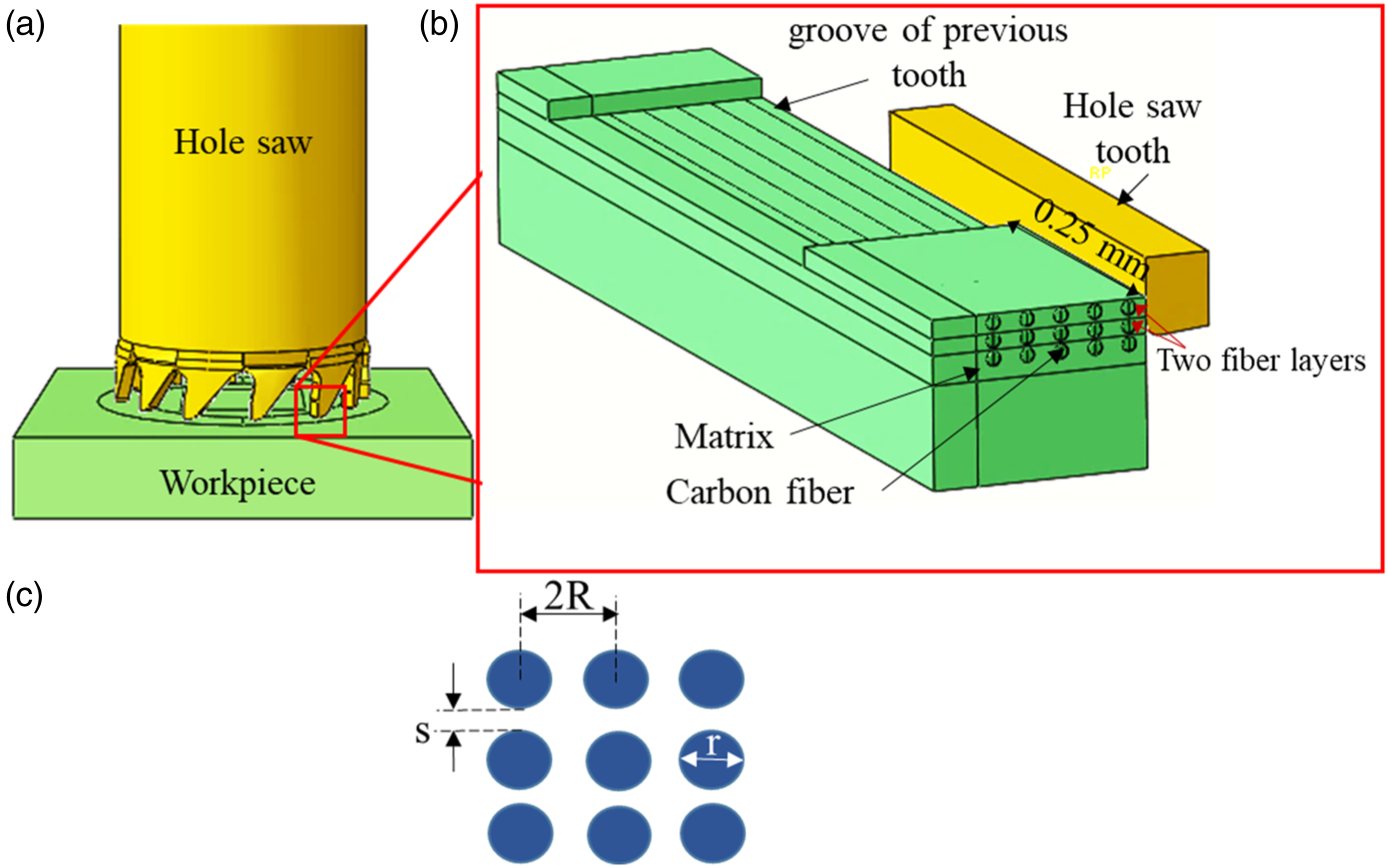
It’s noteworthy that a comparison was conducted between the numerical results derived from the hole saw drilling process and the experimental results, revealing a substantial level of agreement between them. 21
The configuration of the simplified model is established under a set of assumptions. Firstly, it is assumed that the fibers are uniformly distributed within the matrix. Furthermore, the fibers’ arrangement in the matrix is characterized by a regular and square pattern (Figure 1(c)). The fiber volume fraction Vf and the fiber diameter are set at 60% and 10 μm, respectively. The inter-fiber distances, 2R (≈ r/(Vf /π)1/2) 22 and s (≈ r ((π/4Vf)1/2−1)) 22 are equal to 27 and 13.7 μm, respectively.
Description of the FEM Model
A 3D micromechanical model has been devised to replicate the cutting process of a hole saw tooth. The numerical model, depicted in Figure 2, encompasses the geometry, boundary conditions and meshing. The workpiece has a dimension of 850*300*150 μm3 containing a groove of dimension 0.5 mm presenting the width of the tooth in front. The workpiece is composed of two parts: the first part represents the Equivalent Homogeneous Material (EHM), and the second part depicts the different constituents of the composite, such as the fiber, the matrix, and the interface. The cutting tool used in this study is a hole saw tooth. This tool is assumed to be rigid, with a rake angle of 0°, a clearance angle of 5° and a cutting-edge radius of 0.01 mm. Geometrical model, boundary conditions and meshing.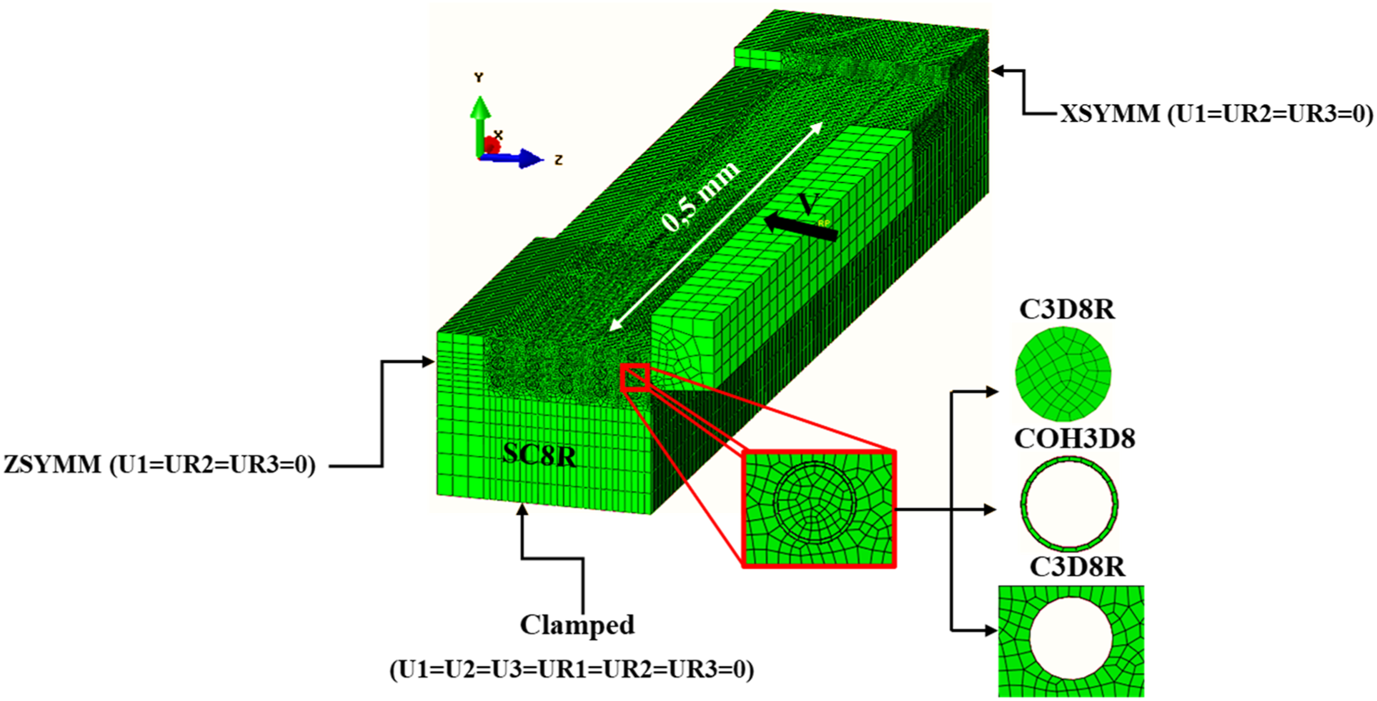
The machining process involves a cutting speed (Vc) of 33 mm/min, a feed rate of 15 μm per tooth per revolution and a depth of cut of 0.5 mm. These parameters are set based on cutting parameters used when drilling CFRP with a hole-saw tool. Specifically, the experimental spindle speed (N) of 1000 r/min results in a cutting speed of approximately 33 mm/min. To simplify the analysis of chip formation mechanisms, the feed per tooth is set in a way that only one fiber layer is removed by the right part of the tooth, corresponding to a depth of cut of 0.25 mm, and two fiber layers for the remaining depth of cut (see Figure 1).
The workpiece has a clamped base, while the straight surface exhibits symmetry around the x-axis, and the surface parallel to the tool displays symmetry around the z-axis.
The 3D micromechanical model enforces various interactions, including: (i) interactions among different constituents of the composite and (ii) interactions between the tool and the workpiece. To define these interactions, the ‘GENERAL CONTACT’ algorithm provided in Abaqus/explicit is utilized. The coulomb friction law (equation (1)) is used to govern the contact between the tool and the various part components, with a constant friction coefficient of 0.5.
23

In this model, three different mesh types are employed. The matrix and fibers are represented using a C3D8R mesh. For the interface, cohesive elements of COH3D8 type are employed. Finally, the EHM is meshed using SC8R-type elements. Specifically, a fine mesh is applied to the contact zone between the tool and the workpiece to capture details accurately, while a coarse mesh is used in other regions for computational efficiency. The number of nodes and elements in the workpiece varies from 399 931 to 613 425 and from 331 654 to 475 697, respectively, depending on the fiber orientation angle. The tooth is meshed with number of nodes and elements of around 17139 and 17278, respectively.
Materials Properties
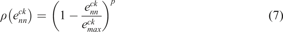
In the present model, behavior and damage laws of various constituents of the composite material are independently defined. The epoxy matrix displays an isotropic elasto-plastic behavior coupled with ductile damage law. 17 The latter is used to underscore the initiation and evolution of damage resulting from nucleation, growth, and coalescence of voids within the matrix. 24
Damage Initiation
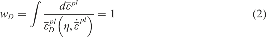
The model postulates that the equivalent plastic strain at the beginning of damage is formulated as a function of stress triaxiality and strain rate (equation (2)). The damage initiation occurs when the state variable
Damage Evolution
The damage evolution is defined by the damage variable, d, which is a function of the effective plastic displacement, as shown in equation (3):
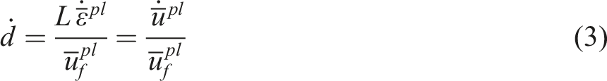
According to the equation (3), when the effective plastic displacement equals tohe effective plastic displacement at failure, the material stiffness experiences complete degradation, denoted by d = 1.
The carbon fiber is assumed to have isotropic elastic behavior modeled by the Hooke’s law and the ‘Brittle Cracking’ model. 25
The elastic behavior of the fiber’s material (Hooke’s law) is modeled by the following relationship:

To describe the initiation and evolution of fiber damage, the “brittle cracking” model is employed. The detection of crack initiation is governed by the Rankine criterion. 24 This criterion asserts that a crack will develop when the maximum principal tensile stress surpasses the tensile strength of the brittle material.
The crack initiation is based on the mode I failure (tension Softening), while post-crack behavior (damage evolution) includes mode II (shear softening/retention) as well as mode I.
Hillerborg establishes the energy needed to initiate a crack in mode I (

The Mode II shear response indicates that the shear behavior is influenced by the extent of crack opening. Particularly, the shear modulus after cracking diminishes as the crack opens. Therefore, a shear retention model is proposed, in which the post-crack shear stiffness is defined as a function of crack opening strain. The post cracking shear modulus (Gc) is written as a function of the uncracked shear modulus (G) as follows:

The shear retention can be defined as a power law:
The EHM has an orthotropic elastic behavior and its constitutive law is described in reference.
11
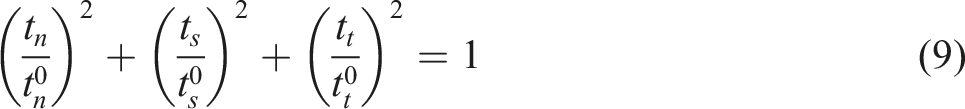
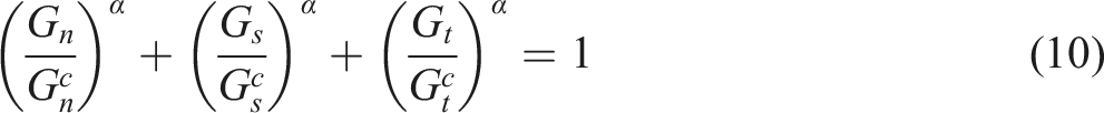
However, this material does not include a damage model, because it does not encounter the tool. The fiber orientation of the EHM takes two values, 0 or 90°, depending on the studied case. Nevertheless, the interface exhibits an elastic law, delineated by the application of the tensile-separation law, which is described by the following relationship:24,26

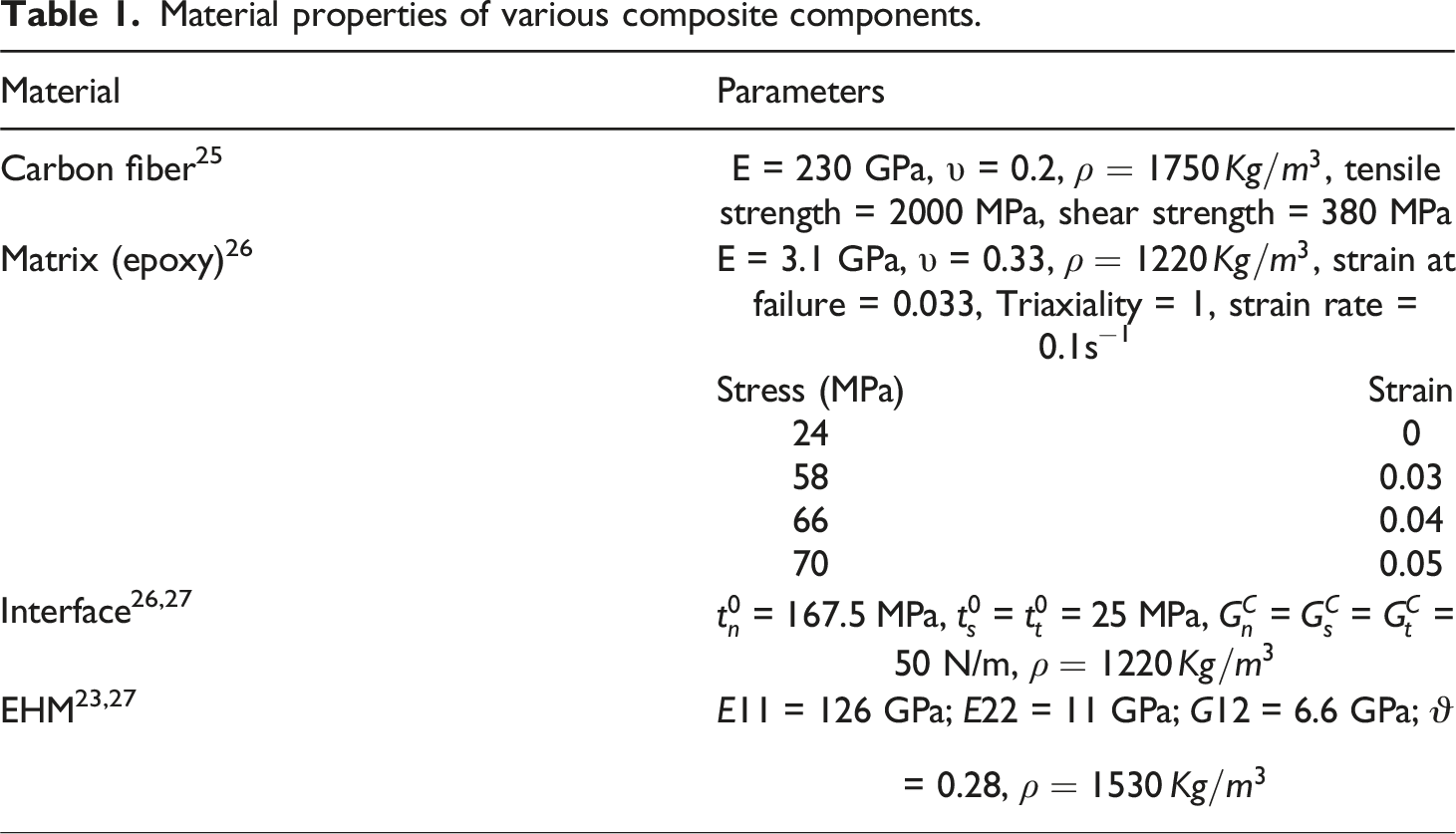
Material properties of various composite components.
Results and Discussion
In this study, the effect of tool’s geometrical parameters, namely the rake angle (γ), the inclination angle (λ𝑠) and the edge radius (Rβ) on chip formation mechanisms, cutting force and lateral damage (Figure 3) are examined. Due to the specific direction of fibers in unidirectional composite, the direction of the cutting speed during drilling varies at any time in relation with fiber orientations. The fiber orientation angle (θ), which is the relative angle between the direction of the cutting speed and the orientation of uncut fibers, varies continuously from 0 to 180°. To simplify this study, two fibers orientation angles are being tested: 0 and 90°. Furthermore, our investigation is limited to these orientations, since according to the literature,10,12,15 the 90° fiber orientation angle generates the greatest cutting force and damage. The numerical simulations to be performed and the corresponding used parameters are illustrated in Table 2. The choice of tool geometrical parameters is based on recommendations and values found in the literature.28–31 For instance, according to Lopresto et al.,
31
a rake angle higher than 30° cannot be industrially adopted. Regarding values of inclination angle and cutting-edge radius, the same order of magnitude as reported in the literature has been retained.28–30 Different tool’s geometric parameters (a) rake angle, (b) inclination angle and (c) cutting edge radius. Numerical tests and corresponding geometrical parameters.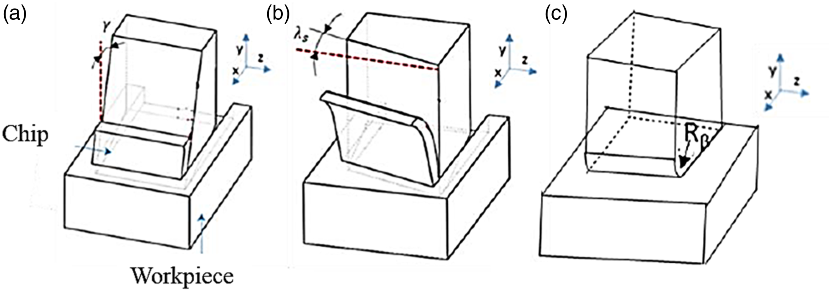
Effect of Rake Angle
In this section, the effect of the rake angle on chip formation mechanisms, cutting force and lateral damage is analyzed. Three rake angles have been tested 0, 10 and 20° for two fiber orientations 0 and 90°.
Cutting Force
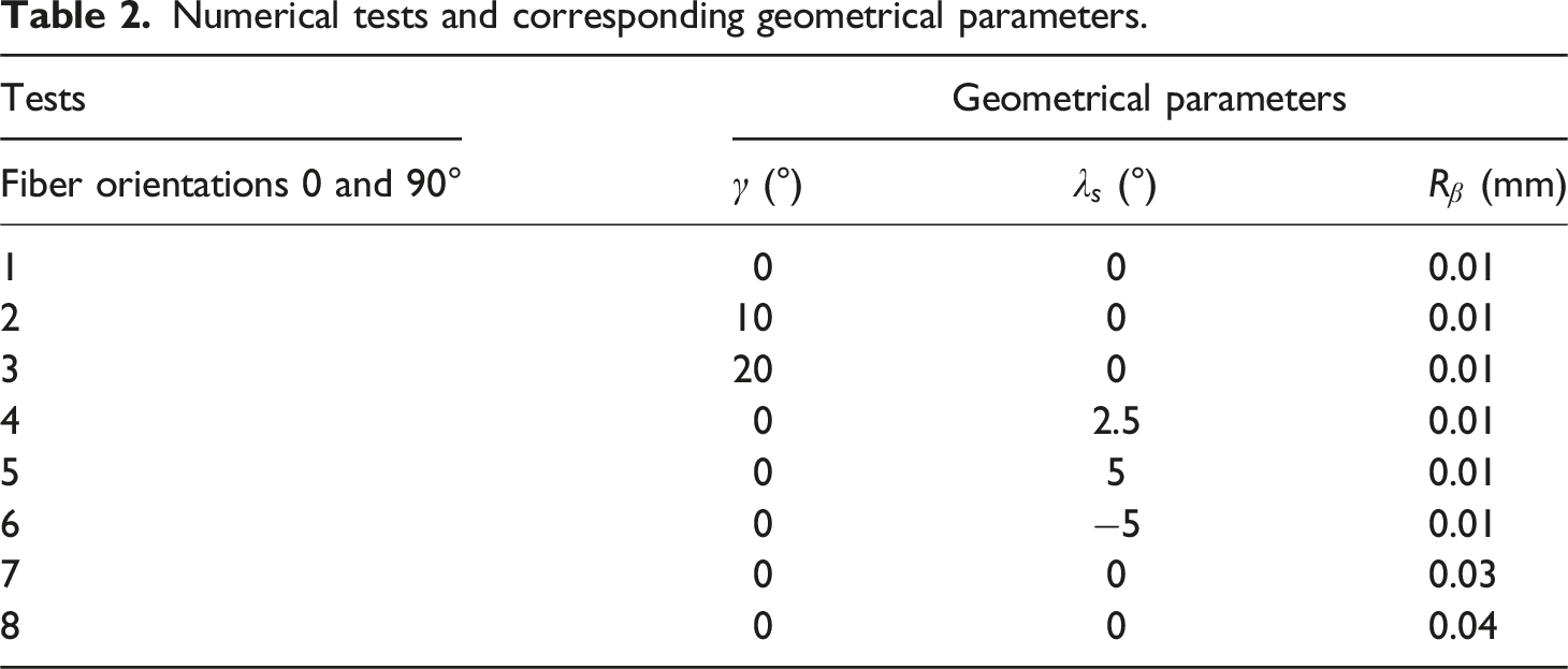
Figure 4 shows the evolution of the cutting force as a function of the rake angle for two different fiber orientation angles, namely 0° and 90°. The outcomes demonstrate a substantial reduction in the cutting force as the rake angle increases. Specifically, there is a noteworthy decline of 50% and 40% when the cutting angle shifts from 0° to 20° for fiber orientation angles of 0° and 90°, respectively. Indeed, increasing the rake angle leads to a reduction in the contact area between the tool and the workpiece, which in turn modifies the chip-forming mechanisms and reduces the cutting force. The same finding was reported by Mkaddem et al.
32
during the orthogonal cutting of GFRP. Furthermore, Sui et al.
33
revealed that the cutting force decreases with increasing the rake angle during the orthogonal cutting of bovine bone. It is important to highlight that a higher rake angle, which corresponds to a sharper cutting edge, hastens the fracturing of fibers, and facilitates their smooth flow. Effect of rake angle on cutting force for different fiber orientation angles, 0° inclination angle and 0.01 mm cutting edge radius.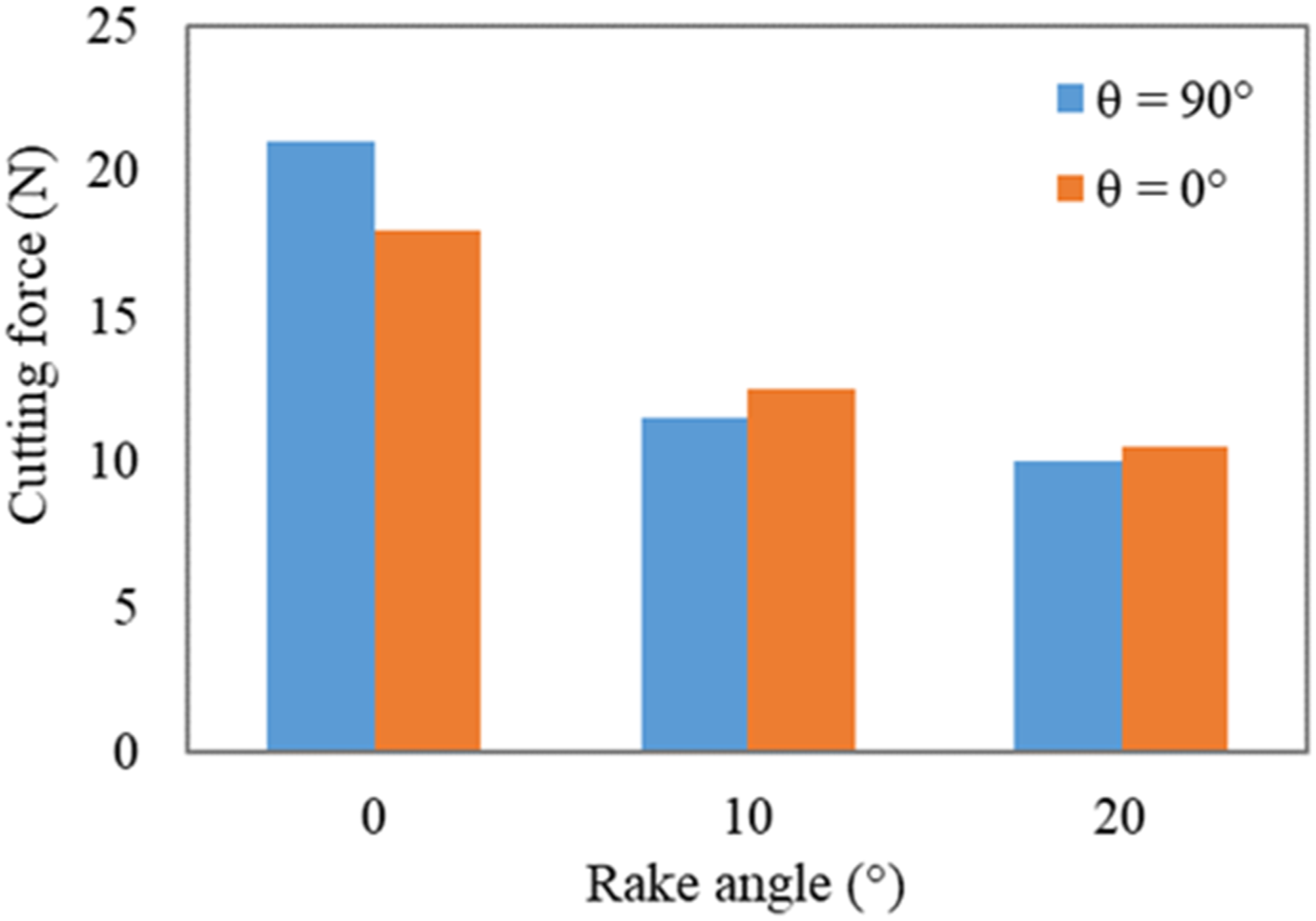
Chip Formation Mechanisms and Machining Quality
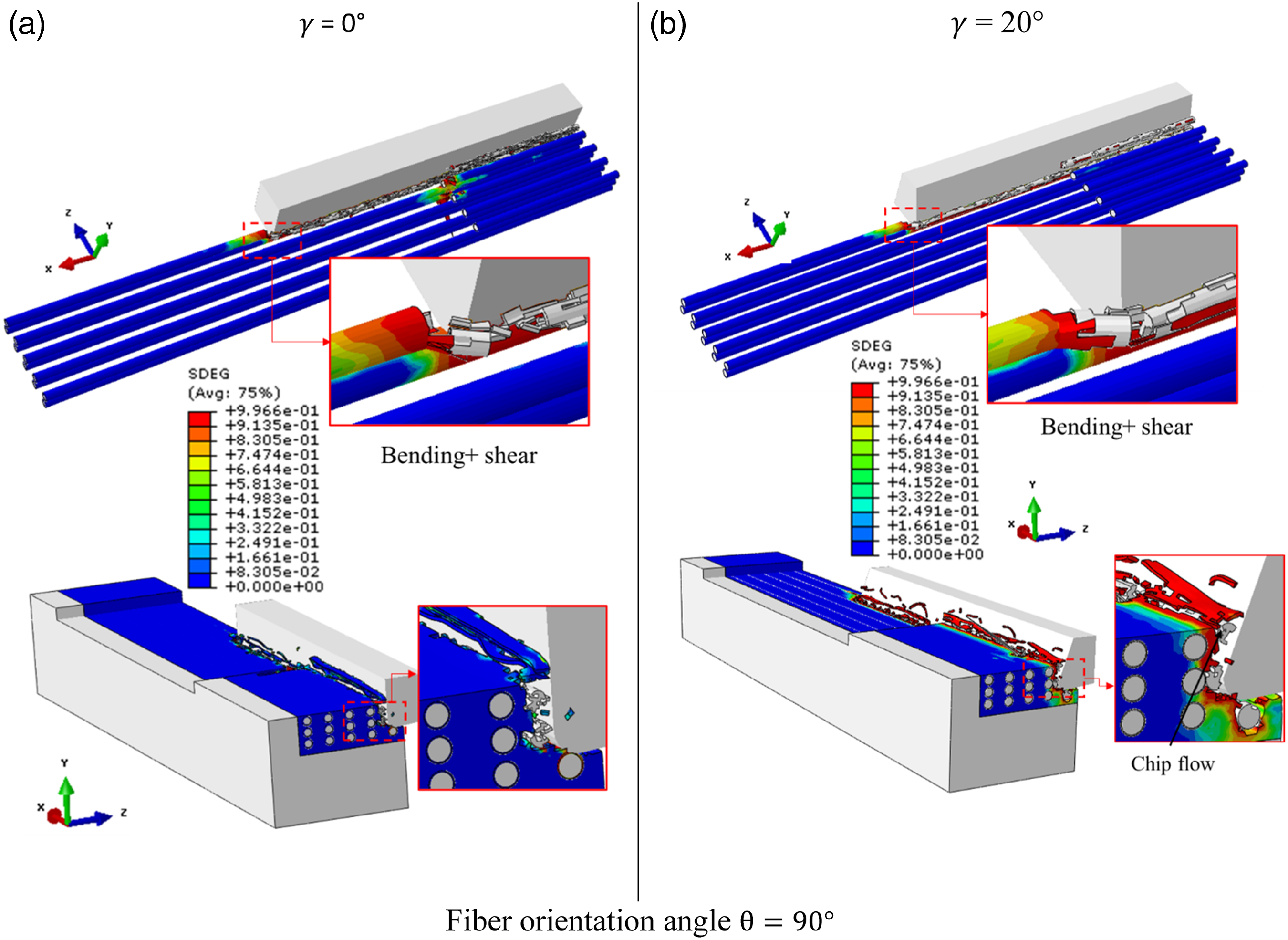
Figures 5 and 6 depict chip formation mechanisms corresponding to two distinct rake angles, namely 0 and 20°, and two different fiber orientation angles, 0° and 90°. The analysis of these figures reveals that the rake angle plays a substantial role in influencing chip formation mechanisms. Effect of rake angle on chip formation mechanisms for θ = 90°, 0° inclination angle and 0.01 mm cutting edge radius: (a) γ = 0° and (b) γ = 20°.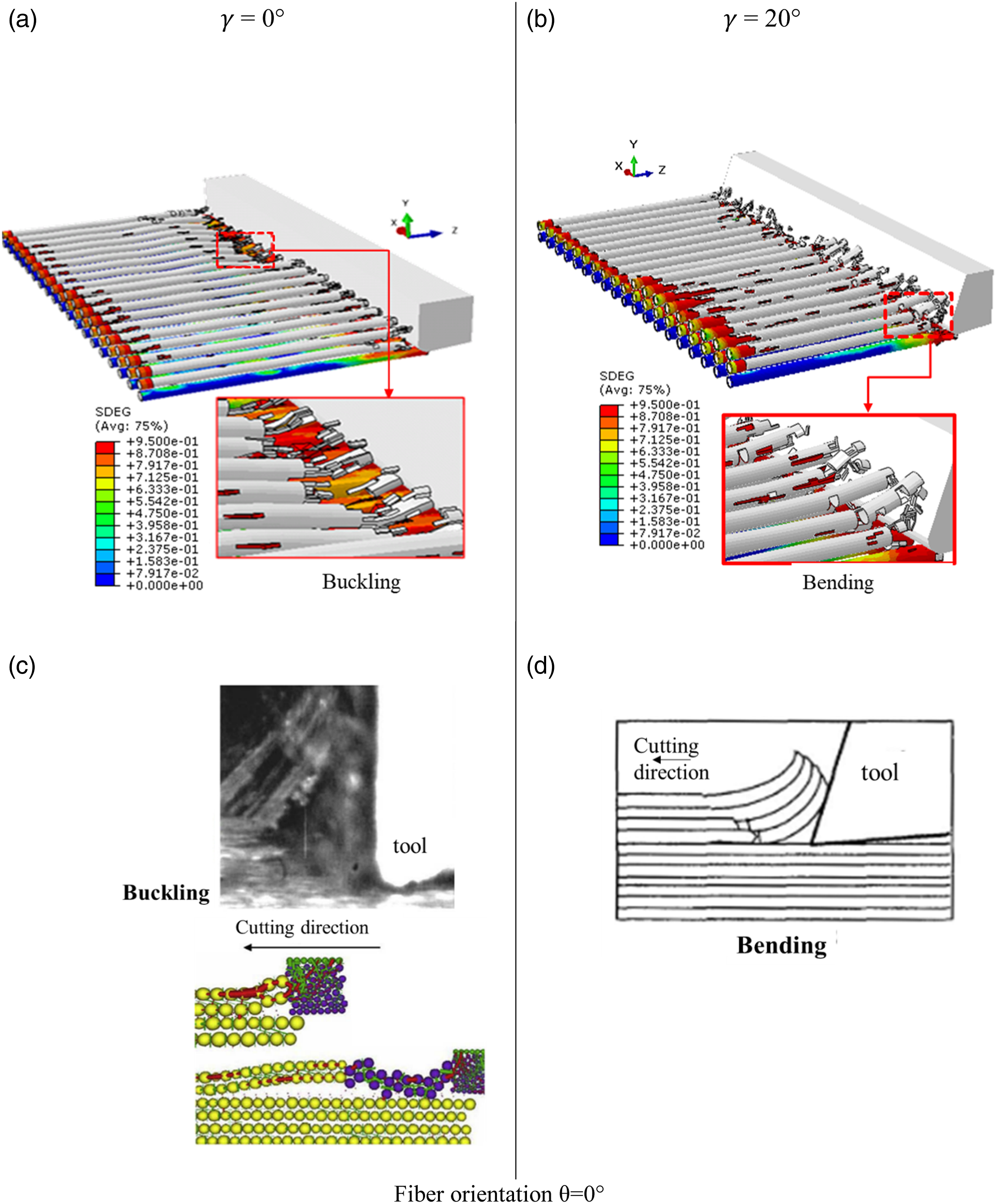
For a fiber orientation angle of 0° and a rake angle of 0° (Figure 5(a)), the advancement of the cutting tool results in the fibers detaching from the matrix through decohesion of the fiber-matrix interface. Afterward, an occurrence of mode I rupture combined with a fiber buckling mechanism has been witnessed. Subsequently, a crushing mechanism comes into play, leading to the promotion of mode II rupture. However, for a rake angle of 20° (Figure 5(b)), the chip formation is achieved through bending. Indeed, driven by the tool’s progress, the fibers begin to deform (through bending) until they reach the flexural rupture strength, which indicates the fracture in mode II. This result was confirmed by Calzada et al., 34 who demonstrated that the bending mechanism governs the rupture of fibers oriented at 0° during the orthogonal cutting of CFRP with a positive rake angle. In addition, Iliescus et al. 35 indicated that, in the orthogonal cutting of CFRP with a zero-rake angle, the rupture of fibers oriented at 0° is primarily governed by the buckling mechanism. It can be seen that when the rake angle is increased, the fibers flow onto the rake face, making them easier to break.
For a fiber orientation angle of 90° (Figure 6), the motion of the cutting tool leads to the fracture of the matrix followed by the fiber fracture through shear and bending mechanism perpendicular to their axis, thus reflecting the primary rupture. As for the secondary fracture, it initiates at the end of the primary rupture and propagates parallel to the fiber axes through fiber/matrix decohesion. The identical outcomes were reported by Cheng et al. 18 when micro cutting of CFRP. They found that fibers experience both shear and bending loads concurrently. Furthermore, Zhang et al. 36 proved similar finding during the orthogonal cutting of CFRP using experimental tests. They showed that for 90° fiber orientation angle, the fiber-matrix debonding begins firstly, followed by subsequent fiber bending deformation. Ultimately, the fiber fractures under shear forces.
It can be observed that increasing the rake angle enhances the fiber shear and bending mechanisms and facilitates material flow on the tool’s rake face, which aids in chip evacuation.
Within this part, we will explore the impact of the rake angle on the surface quality. Our accent is to evaluate the damage at a 90° angle due to its heightened importance compared to the observations made at 0°. This finding was further confirmed in the literature.
30
Figure 7 displays the distribution of damage in the workpiece across various rake angles. The results reveal that the damage occurs not only within the contact region between the workpiece and the tool but also extends sideways. The lateral damage within the workpiece measures approximately 65 μm and 68 μm for rake angles of 0° and 20°, respectively. This slight increase in damage can be attributed to stress concentration in the workpiece induced by the 20° rake angle. A similar results were found by Lopresto et al.
31
during the orthogonal cutting of unidirectional composite material. Their study demonstrated that as the cutting angle increased, damage also increased, especially for fiber orientation angles of 90° and 120°. effect of rake angle on workpiece damage for θ = 90°, 0° inclination angle and 0.01 mm cutting edge radius: (a) γ = 0° and (b) γ = 20°.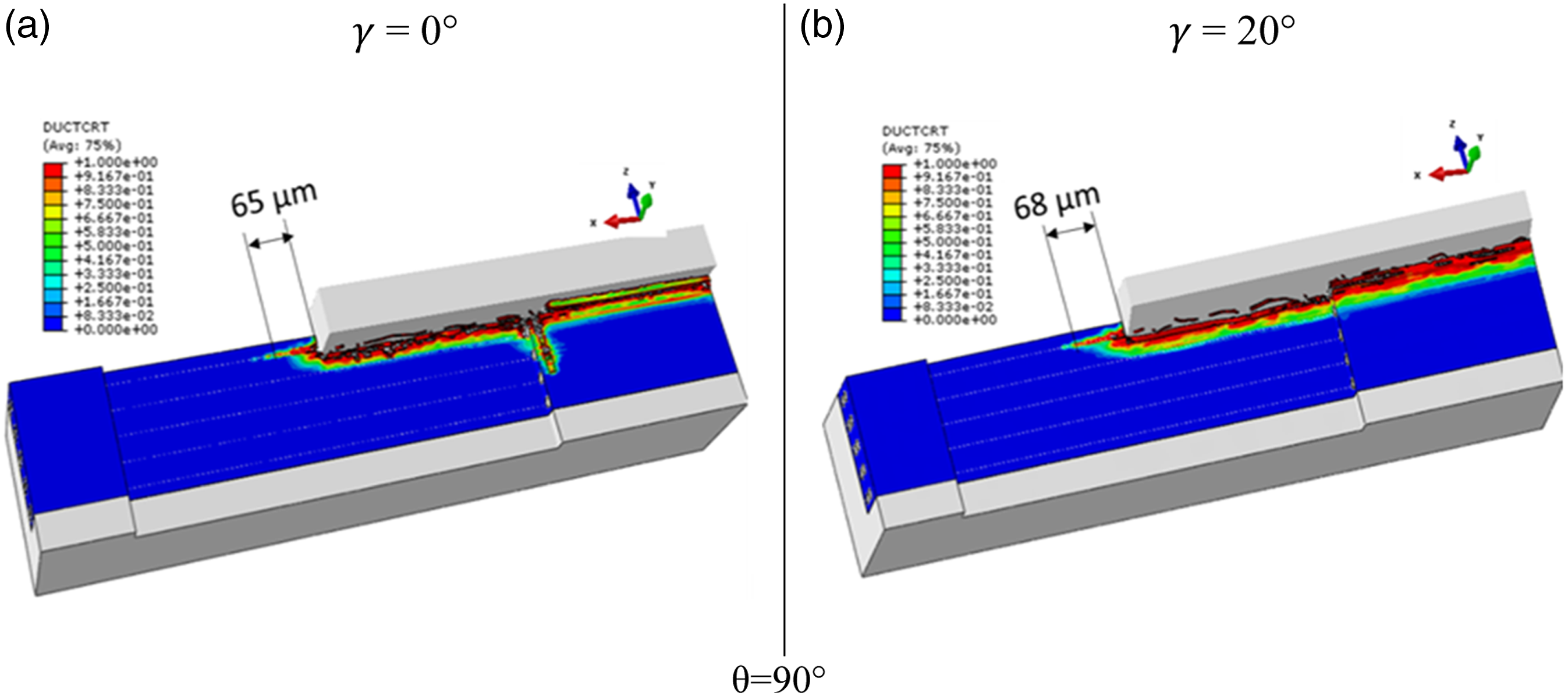
Stress Analysis
Figures 8 and 9 show the stress distribution in the workpiece for 0 and 90° fiber orientation angles, respectively. Figure 8(a) and (b) represents the stress distribution in fibers for 0° fiber orientation angle and for 0 and 20° rake angles, respectively. It is seen that the maximum stress is located far from the fiber rupture zone. In fact, when fibers are compressed, the front part of the fibers in contact with the tool is broken and the stress in the rest of the fibers is increased, creating a zone of brittleness. The analysis of this Figure (8(a) and (b) revealed that the stress generated by a rake angle of 0° is higher than that obtained for a rake angle of 0°. The stress distribution in the matrix for both 0 and 20° rake angles is illustrated in Figure 8(c) and (d). The observation reveals that the peak von Mises stress measures approximately 67 MPa, and it is similar for rake angles of 0 and 20°. Furthermore, the von Mises stress generated by the tool/workpiece contact propagates in front of the tool towards the end of the workpiece and extend below the cutting plane. Von Mises stresses distribution in fibers and matrix for 0° fiber orientation and for (a), (c) 0° rake angle and (b), (d) 20° rake angle. Von Mises stresses distribution in fibers and matrix for 90° fiber orientation and for (a), (c) 0° rake angle and (b), (d) 20° rake angle.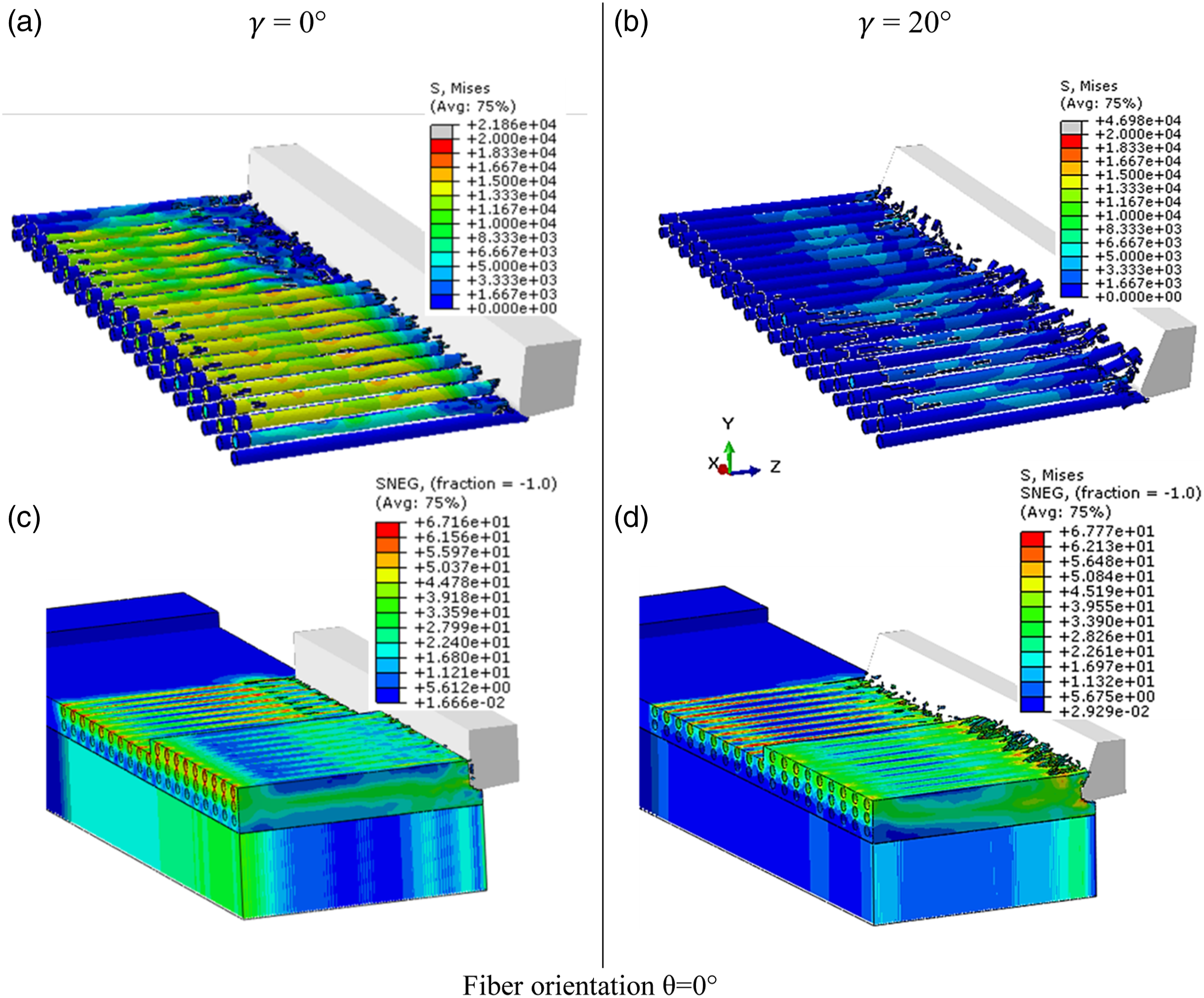
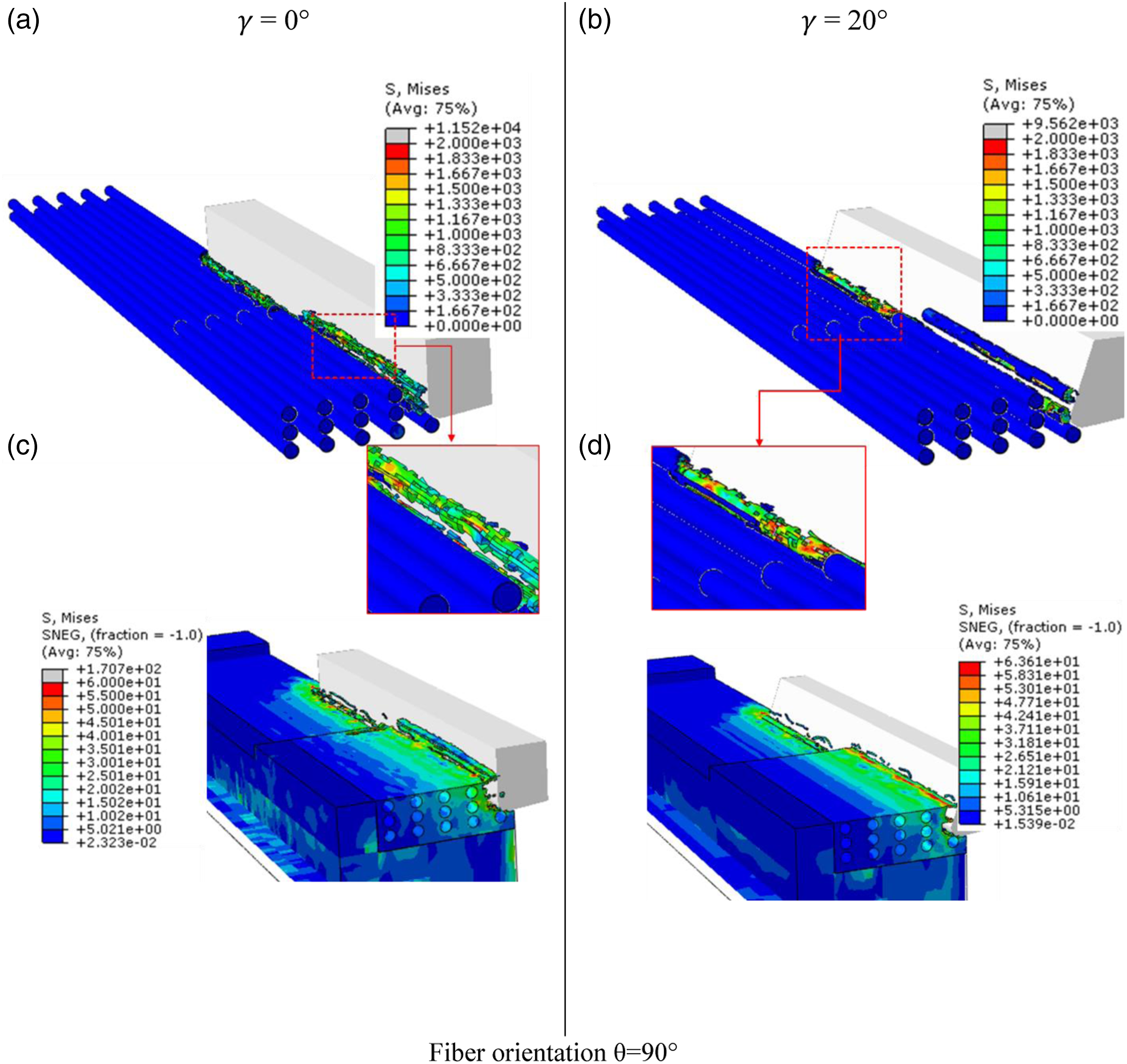
The examination of the stress distribution in fibers for a fiber orientation angle of 0° (see Figure 9(a) and (b)) shows that the maximum stress for 0° rake angle, which is about 1.1 × 10⁴ E4 MPa, is higher than that observed for the 20° rake angle, which is approximately 9.5 E3 MPa. The highest stress is situated within the fiber that comes into contact with the tool. The same finding is observed in the Figure 9(c) and (d), where the von Mises stress in the matrix for a rake angle of 0° is significantly higher than for 20°.
For both 0° and 90° fiber orientation angles, the maximum stress in the matrix is lower than that observed in fibers, which is justified by the fact that the breaking strength of the matrix and its stiffness is lower than that of the fiber. This result is confirmed by Song et al. 26
Effect of Inclination Angle
To investigate the sensitivity of chip formation mechanisms, cutting force, and lateral damage to the inclination angle, four angles 0, 2.5, −5, and 5° were evaluated, including positive and negative inclination angles.
Cutting Force
Figure 10 illustrates the evolution of the cutting force as a function of the inclination angle for two fiber orientation angles, 0° and 90°, in the steady-state regime. Examination of this figure reveals a decline of the cutting force with the increase of the inclination angle. In the case of a fiber orientation angle of 90°, a substantial reduction of 85% is attained by varying the inclination angle from 0 to 2.5°. Nevertheless, marginal alteration in the cutting force was observed when using greater inclination angles. For a fiber orientation angle of 0°, the cutting force shows a declining trend as the inclination angle changes. A decrease of 51% is viewed by raising the inclination angle from 0 to 5°. Such a trend is explained by the reduction in the chip thickness as the inclination angle increases. This finding was also corroborated by Pal et al.
38
during the orthogonal cutting of aluminum. It is important to highlight that as the inclination angle rises, the cutting force for a 0° fiber orientation surpasses that of a 90° fiber orientation. Evolution of cutting force as a function of inclination angle for 0° rake angle and 0.01 mm cutting edge radius.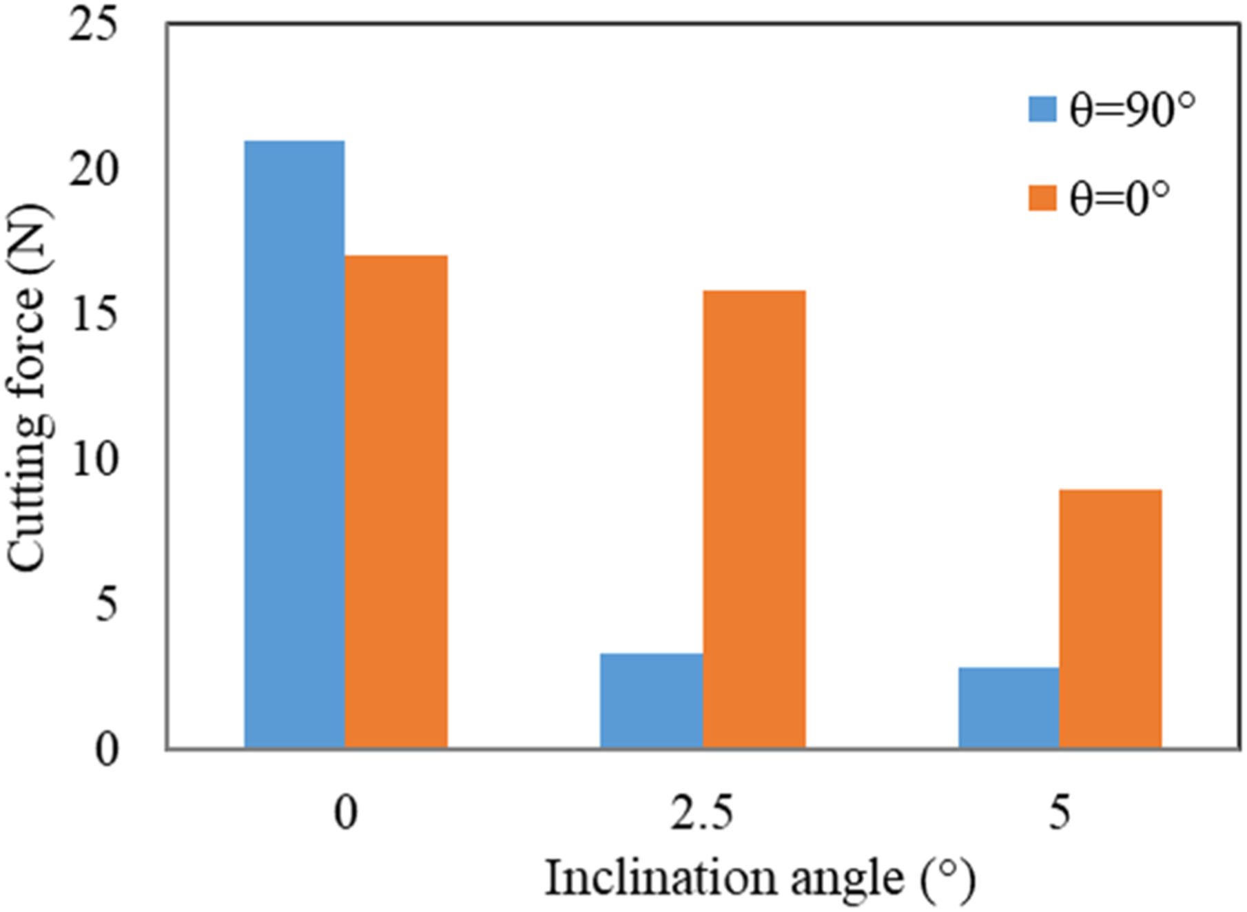
Chip Formation Mechanisms and Machining Quality
In Figure 11, a comparison of chip formation mechanisms is displayed, involving two different inclination angles (0° and 5°) and two distinct fiber orientation angles (0° and 90°). It is essential to highlight that the inclination angle plays a significant role in shaping the resultant chip formation mechanisms. For a fiber orientation angle of 0° and an inclination angle of 0° (Figure 11(a)), the tool’s impact on the workpiece causes the breaking of the fiber-matrix interface and the crushing of fibers. This leads to a reduction in the fiber length because of the removal of these elements, and the appearance of weakness zones characterized by a reduction in the fiber diameter. On the other hand, at an inclination angle of 5° (Figure 11(b)), as soon as fibers are crushed, they fragment completely, giving rise to small chips. Chip formation mechanisms for 0° rake angle, 0.01 mm cutting edge radius, different fiber orientation angles and various inclination angles (a) 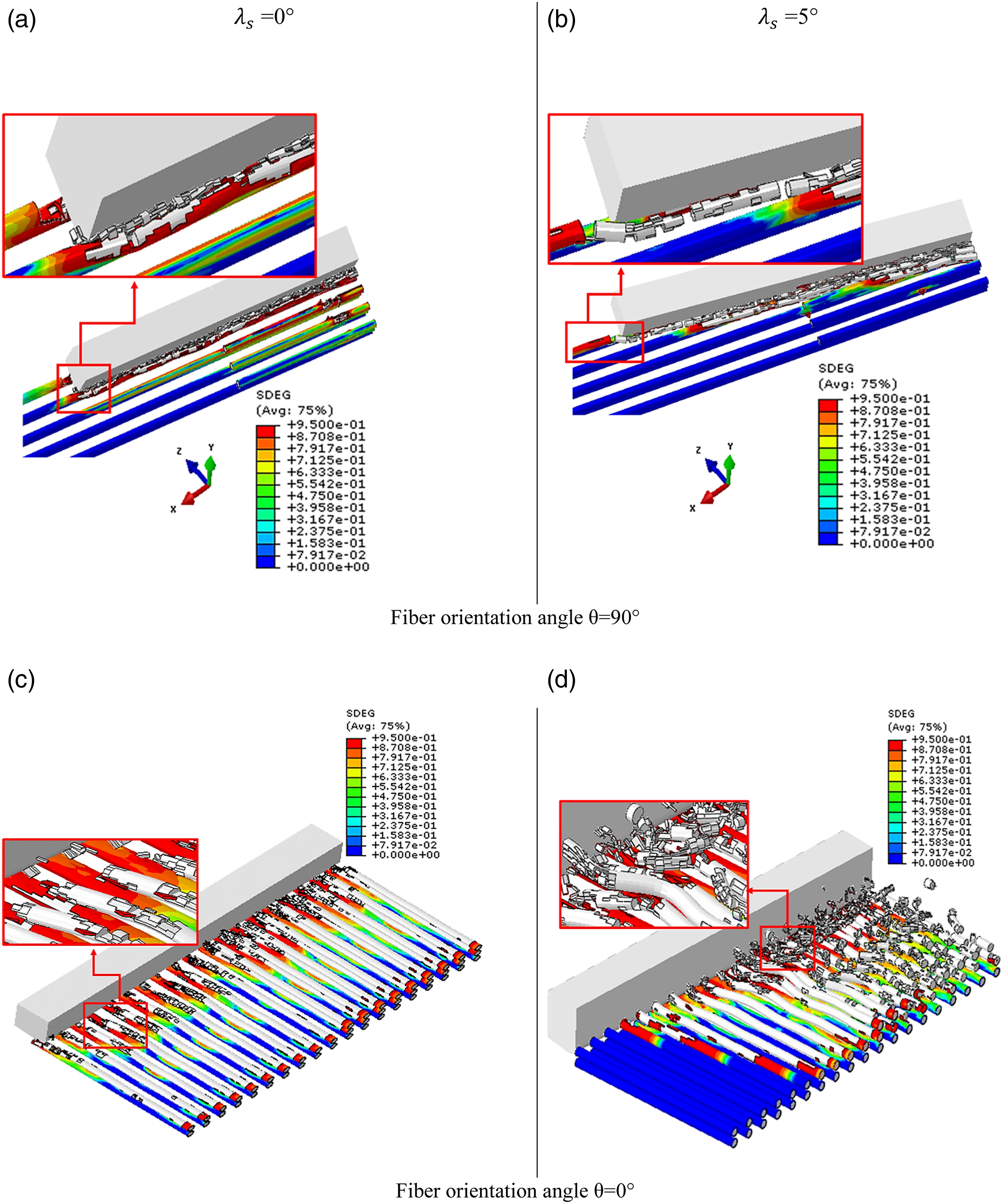
For a fiber orientation angle of 90° (Figure 11(c) and (d)), the process unfolds with the tool feed causing initial fractures in the matrix, followed by the disruption of the fiber-matrix interface. The stress continues to propagate until they reach fibers. Upon surpassing the breaking stress threshold, shearing and bending mechanisms come into play, resulting in the fracture of fibers for both 0° and 5° angles of inclination. When the inclination angle is 0°, the fiber that encounters the tool upon breakage undergoes compression, leading to the rupture of the fiber-matrix interface of the fiber ahead. Subsequently, this fiber breaks at a different location compared to the one preceding it. However, when the inclination angle is 5°, the tool’s contact with the first fiber causes its fragmentation into small particles. This, in turn, triggers rupture of the fiber-matrix interface of the 2nd and 3rd fibers ahead. As a result, the bending mechanism at the ends of the 2nd and 3rd fibers is intensified and becomes the dominant failure mode.
It is noticeable that for the 0° fiber orientation (Figure 11(a) and (b)), increasing the inclination angle from 0 to 5° results in a more fragmented chip. Comparable outcomes were noted for the 90° fiber orientation (Figure 11(c) and (d)), where an increase in the inclination angle promotes the fiber fragmentation and reduces the number of damaged fibers in front of the tool. This observation underscores the heightened significance of the fiber crushing mechanism as the inclination angle is raised.
To elucidate the intricate mechanisms underlying chip formation, schematic representation of chip formation mechanisms for 0° rake angle, 0.01 mm cutting edge radius, different fiber orientation angles and various inclination angles are shown in Figure 12. This figure provides valuable insights, unequivocally confirming that the process of chip fragmentation gains momentum as the inclination angle intensifies. This figure serves as a convincing confirmation that shear and bending predominantly govern the chip formation mechanism when the fiber orientation is at 90°. Conversely, when the fiber orientation is at 0°, buckling takes precedence as the dominant mechanism. When 0° inclination angle was used, the tool is in contact with all frontal fiber providing the buckling of the fiber layer. However, increasing the inclination angle to 5° provokes a decrease of the number of fibers in contact with the tool, generating the rupture of the buckled fiber and several fragmented ships. Schematic representation of chip formation mechanisms for 0° rake angle, 0.01 mm cutting edge radius, different fiber orientation angles and various inclination angles (a) 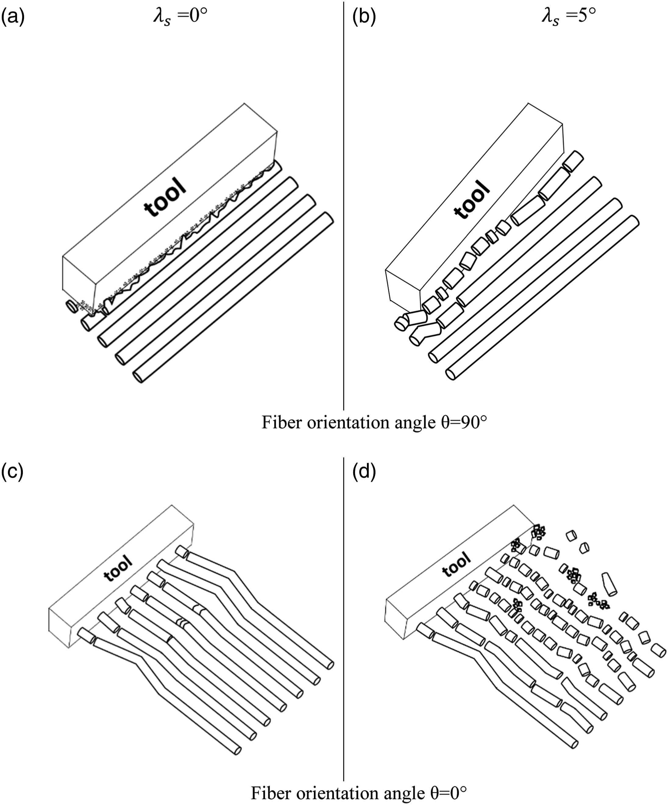
Figure 13 depicts the distribution of damage in the workpiece for a fiber orientation of 90° and three inclination angles: 0°, 5°, and −5°. The objective behind altering the inclination angle’s orientation (positive and negative angles) is to evaluate its effect on the damage of the machined workpiece. It is evident that the lateral damage for both 5° and −5° inclination angles is more extensive than that at 0°. At a 0° inclination angle, the lateral damage measures 80 μm, while at −5° and 5° inclination angles, the lateral damage is 104 μm and 88 μm, respectively. It is notable that varying the inclination angle from 0° to 5° (positive angle) doesn’t have a substantial influence on the lateral damage, but it notably reduces the damage upstream of the tool. Conversely, modifying the inclination angle from 0° to −5° (negative angle) substantially heightens the extent of lateral damage. An increase of about 30% is observed when varying the inclination angle from 0 to −5°. The lateral damage for an inclination angle of −5° is more significant than that for 5°. It can be concluded that obtaining a good surface quality requires a reduction in upstream tool damage and lateral damage, therefore an inclination angle of 5° is recommended. Effect of inclination angle on lateral damage for 90° fiber orientation, 0° rake angle and 0.01 mm cutting edge radius: (a) 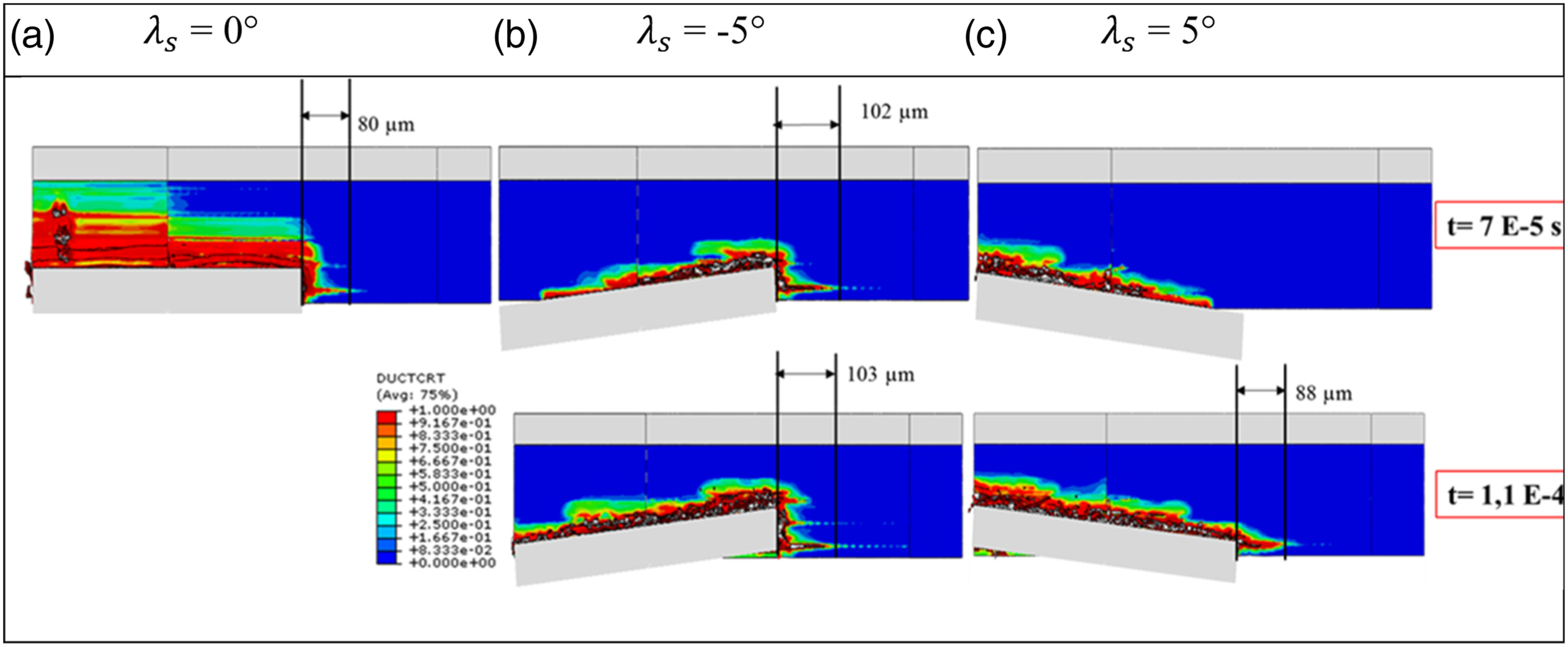
Effect of Cutting-Edge Radius (Rβ)
To investigate the impact of the tool’s edge radius on chip formation mechanisms, cutting force, and material damage, three distinct cutting-edge radii were examined, namely, 0.01, 0.03, and 0.04 mm.
Cutting Force
Figure 14 highlights the effect of the tool’s cutting-edge radius on the cutting force while varying the fiber orientation angles. It’s noticeable that for both fiber orientation angles, the cutting force decreases as the tool’s cutting-edge radius increases. Indeed, when considering a fiber orientation angle of 0°, an increase in the cutting-edge radius induces a transition of the chip formation mechanisms from buckling to bending, resulting in a reduction of the cutting force. Certainly, as the cutting-edge radius increases, the fibers in front of the tool undergo a sudden rupture, which reduces the energy required for chip separation. Conversely, in the case of a 90° fiber orientation angle, an enlarged cutting-edge radius triggers a transition of the fiber breaking mechanisms from bending to a combination of bending and compression. This shift aids the material removal and contributes to a reduction in the cutting force. Evolution of cutting force as a function of cutting-edge radius for 0° rake angle and 0° inclination angle.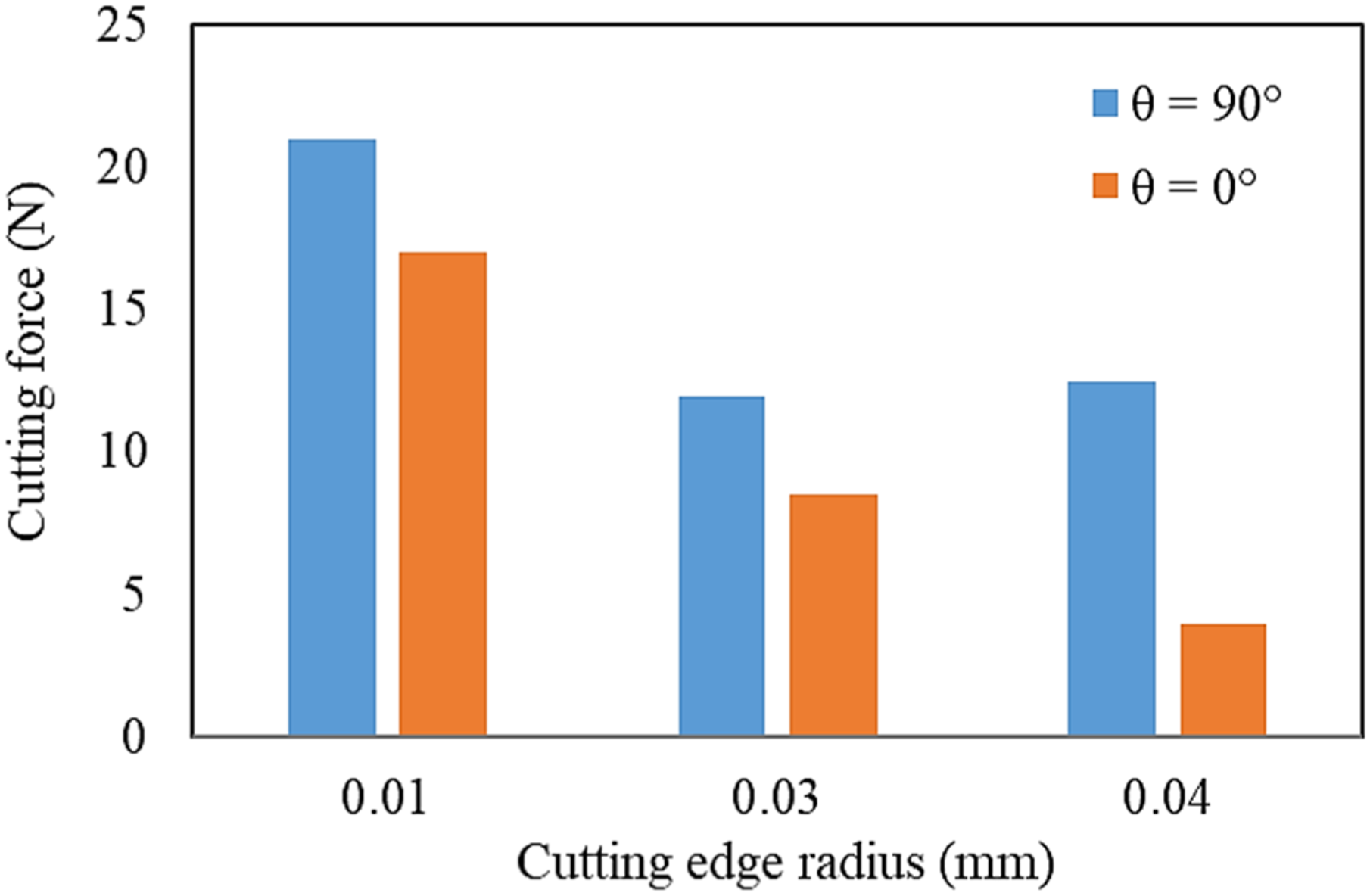
Chip Formation Mechanisms and Machining Quality
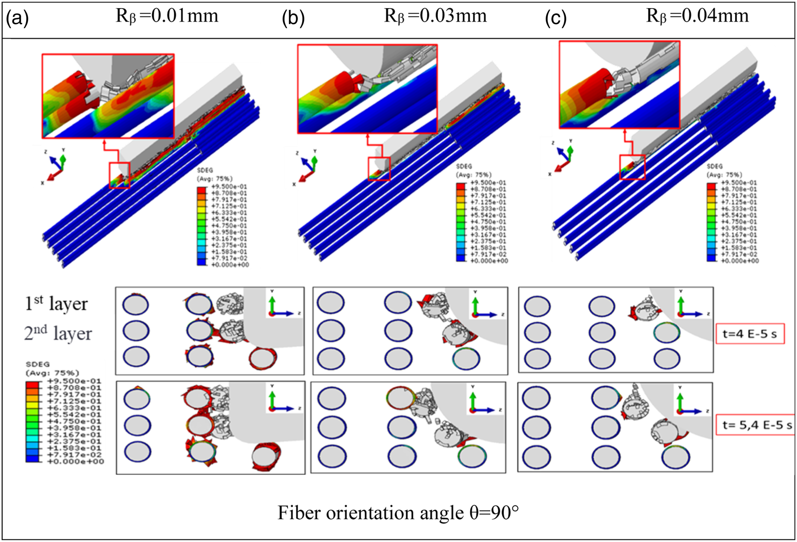
Figures 15 and 16 depict the chip formation mechanisms for two fiber orientation angles, 0 and 90°, and various cutting-edge radii. It is seen that chip formation mechanisms are significantly affected by the tool’s cutting-edge radius. Chip formation mechanisms for 0° fiber orientation angle, 0° rake angle, 0° inclination angle and different cutting-edge radii (a) Rβ = 0.01 mm (b) Rβ = 0.03 mm and (c) Rβ = 0.04 mm. Chip formation mechanisms for 90° fiber orientation, 0° rake angle, 0° inclination angle and different cutting-edge radii (a) Rβ = 0.01 mm (b) Rβ = 0.03 mm and (c) Rβ = 0.04 mm.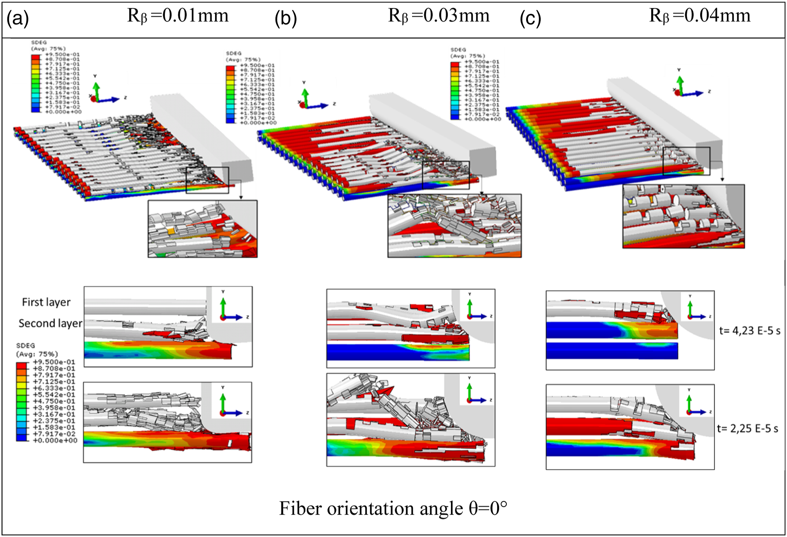
For a fiber orientation angle of 0°, and a cutting-edge radius of 0.01 mm, the tool’s contact with the workpiece leads to the failure of all fiber matrix interfaces in front of the tool. Then, the buckling of fibers, leading to a crushing mechanism (rupture mode II) (Figure 15) and resulting in fiber destruction. In this case, small chips are formed. When the cutting-edge radius is increased to 0.03 mm (Rβ = f), most of the fiber-matrix interfaces in front of the tool are broken. In the first layer, fiber breakage occurs through crushing, whereas in the second layer, fiber breakage results from bending. Long and small chips are produced. Upon reaching a cutting-edge radius of 0.04 mm (Rβ > feed), fibers from both layers undergo bending due to the rounded tip of the cutting tool. It can be noticed that a large cutting-edge radius, causes fibers to shift beneath the cutting plane, potentially increasing subsurface damage. The compression of fibers by the cutting-edge radius results in their fragmentation into small parts.
For a fiber orientation angle of 90° and small cutting-edge radius (0.01 mm), the advance of the cutting tool causes the debonding of the fiber matrix interface and the fracture of fibers by a combination of shear and bending mechanisms. Nevertheless, when dealing with larger cutting-edge radii (0.03 and 0.04 mm), a combined stress involving both bending and compression is applied on the fibers, leading to their fracture (see Figure 16) after detachment of the fiber-matrix interface. The broken fiber of the first layer is pushed forward as the tool advances, while the fiber of the second layer is pushed down by the cutting-edge radius, increasing damage under the cutting plane.
Figure 17 presents the lateral damage in the workpiece for a fiber orientation angle of 90° and various cutting-edge radii. It is observed that small cutting-edge radii (less than or equal to the feed) have a negligible influence on the lateral damage of the machined workpiece. The lateral damage for both radii 0.01 and 0.03 mm is equal to 65 μm. Nevertheless, increasing the tool’s cutting-edge radius to 0.04 mm (greater than the feed) results in the expansion of the damaged area from 65 to 83 μm. Specifically, a 27% increase of damage is observed when varying the cutting-edge radius from 0.01 to 0.04 mm. It can be noted that a low beak radius, not exceeding the value of the feed, does not critically enhance lateral damage. Thus, the use of small cutting-edge radius is strongly recommended to mitigate the damaged zone. In this context, Franke et al.
39
demonstrated that increasing the cutting-edge radius leads to an increase in the burr formation and delamination during the drilling of fiber reinforced plastics using helical drill. Lateral damage for 90° fiber orientation angle, 0° rake angle, 0° inclination angle and different cutting-edge radii (a) Rβ = 0.01 mm (b) Rβ = 0.03 mm and (c) Rβ = 0.04 mm.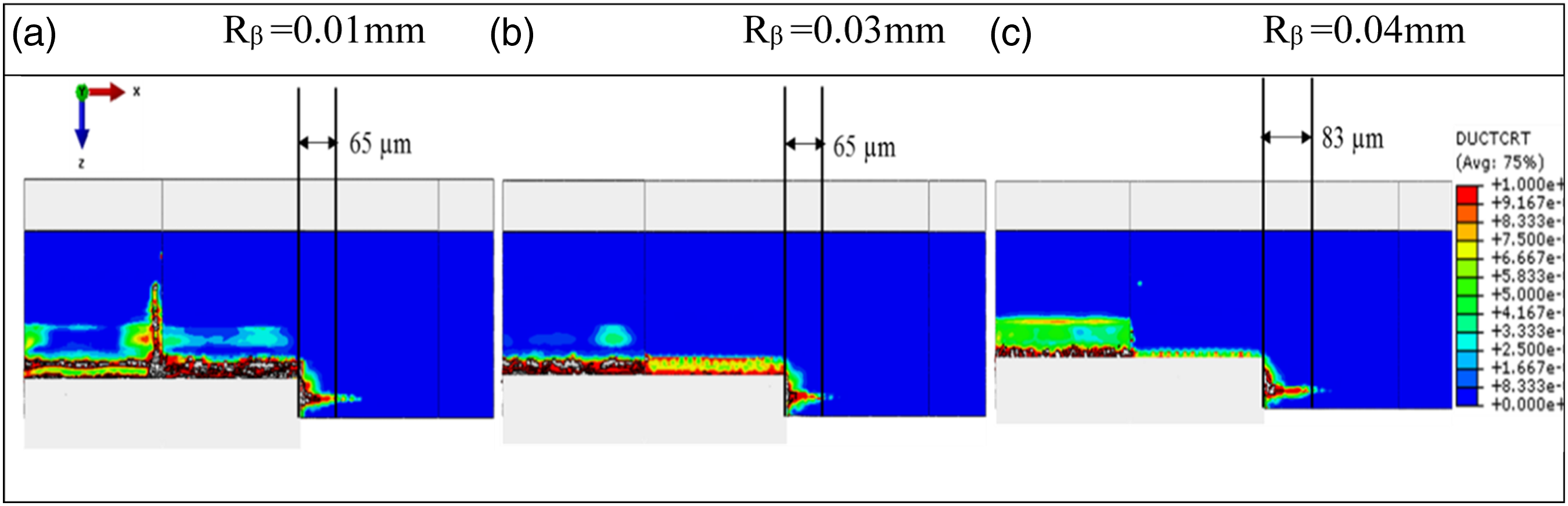
Conclusion
In this research work, the influence of the rake angle, inclination angle, and cutting-edge radius on chip formation mechanisms, cutting force, and lateral damage are investigated via a 3D micromechanical numerical model. The outcomes of the present study permit to formulate the subsequent conclusions:
The rake angle significantly influences chip formation mechanisms and cutting force. In the case of a 0° fiber orientation, a transition from fiber buckling rupture to bending mode was observed as the cutting angle rise from 0 to 20°. Conversely, for a 90° fiber orientation, the bending and shear mechanisms dominated fiber rupture irrespective to the cutting angle. In terms of cutting force, a reduction of 50% and 40% occurred as the rake angle increased from 0° to 20° for fiber orientation angles of 90° and 0°, respectively.
The inclination angle has a remarkable effect on chip formation mechanisms and cutting force. Increasing the rake angle from 0° to 5° promotes fiber fragmentation and results in cutting force reductions of 51% and 85% for fiber orientation angles of 0° and 90°, respectively. The lateral damage is highly sensitive to negative inclination angles. Nevertheless, the effect of the positive inclination angle on the lateral damage is considered negligible.
Chip formation mechanisms, cutting force and lateral damage are highly dependent on cutting edge radius. Decreasing the cutting-edge radius favors the fiber breakage, and the chip flow, as well as reducing the lateral damage. Conversely, a small nose radius induces a high cutting force.
In the near future, the present study will be extended to incorporate thermal effects, tooth interaction, and tool damage. This extension aims to explore the impact of these parameters on chip formation mechanisms, cutting force, and workpiece damage. This provides a better accurate finite element model capable of reproducing the drilling process using a hole saw tool.
Footnotes
Declaration of conflicting interests
The author(s) declared no potential conflicts of interest with respect to the research, authorship, and/or publication of this article.
Funding
The author(s) disclosed receipt of the following financial support for the research, authorship, and/or publication of this article: This work was supported and funded by the Deanship of Scientific Research at Imam Mohammad Ibn Saud Islamic University (IMSIU) (grant number IMSIU-RP23029).