
Abstract
Continuous fiber reinforced thermoplastic composites (CFRTP) have been increasingly used in aerospace and rail transport in recent years because of their high strength and light weight. In this paper, the effects of nozzle temperature, printing speed, substrate temperature and layer thickness on the tensile properties and macro/microscopic damage modes of CAF/PA12 printed specimens was systematically investigated. The fiber volume fraction(FVF) of CAF/PA12 filaments was 25.62%. The maximum average tensile strength and tensile modulus of CAF/PA12 printed specimens reached 572.60 MPa and 18.49 GPa, respectively. The results of the cross-sectional analysis indicated that filament toothed fractures and transverse cracks were the main macroscopic failure modes of CAF/PA12 composites. In SEM images, the main microscopic failure modes of CAF/PA12 composite are fiber fracture, fiber pull-out pores and unimpregnated fibers.
Keywords
Introduction
Additive Manufacturing (AM) has the advantages of low cost, mold-less, simple process, forming complex structures and so on, which has been more and more concerned by the manufacturing industry and academia, compared with the traditional manufacturing technology. AM technology mainly includes stereoscopic light-curing molding (SLA), selective laser sintering (SLS), fused deposition manufacturing (FDM), layered solid manufacturing (LOM), and three-dimensional printing and molding (3DP), etc1–3 Nowadays, FDM technology has become the most widely adopted additive manufacturing technology due to its low cost and high flexibility. 4
However, 3D printed components usually exhibit low mechanical properties due to the layer-by-layer manufacturing characteristics of FDM technology and the inherent properties of thermoplastic resins (PLA, ABS, PA5, PEI, PEEK). Many researchers have mixed short fiber5–9 into thermoplastic resins for 3D printing to improve the mechanical properties of composites components. It has been found that although 3D printed short-fiber reinforced composites outperform pure resins, their mechanical properties are still far lower than continuous fiber-reinforced composites.
In recent years, 3D printing technology of continuous fiber reinforced thermoplastic composites (CFRTP) has attracted increasing attention and has been widely applied in fields such as aerospace, transportation, automotive, and marine industries.10–12 Currently, CFRTP printing mainly includes the following two methods: fiber/matrix in situ impregnation printing13–15 and fiber/matrix pre-impregnated filament printing. 16 The former approach refers to the simultaneous feeding of continuous fibers and thermoplastic resin into the printing nozzle for melting impregnation, followed by extrusion deposition from the nozzle.17,18 The latter involves the pre-preparation of continuous fiber reinforced composite prepreg filaments, which are then extruded and deposited. 19
The mechanical properties of composites printed by in situ impregnation method largely depend on processing parameters such as layer thickness, nozzle temperature, printing speed, fiber direction, and fiber content.20–23 Tian et al. 24 found that temperature and pressure are critical parameters to the forming process, which determine the mechanical properties of composites. With the optimized process parameters, 3D printed CFR PLA composites with a fiber content of 27% can achieve the maximum flexural strength of 335 MPa and flexural modulus of 30 GPa. The longitudinal tensile strength and modulus of 3K-CCF/PA12 composites obtained by micro-screw in situ extrusion method were 735.7 MPa and 79.5 GPa, respectively. 15
In the aforementioned method, the impregnation of continuous fibers mainly occurs in the printing nozzle. However, due to the high melt viscosity of the thermoplastic resin and the short impregnation time of the continuous fibers with the resin, the specimens have defects such as pores and dry fibers.13,24 As it is challenging to achieve proper fiber impregnation in the in situ impregnation printing process, researchers have begun to experiment with prepreg filament printing.17,22,23,25 In these studies, prepreg filaments with excellent properties are prepared by filament forming equipment and then fed into the printer to complete the printing. This method results in better impregnation of continuous fibers. Chen et al. 22 utilized the thermo-mechanical coupling process to fabricate CCF/PEEK prepreg filaments and achieved the maximum tensile strength of 509.56 MPa for printed CCF/PEEK specimens under optimized printing parameters. Hu et al. 16 used this method to analyze the effects of printing time, printing speed, and layer thickness on the flexural properties of CCF/PLA composite.
To date, there are plenty of studies for Continuous Carbon Fiber (CCF) and PLA polymer, while less research has been done on other continuous fibers and other polymer, especially aramid fibers and PA12 polymer.20,26,27 Liao et al. 7 reported the thermal and mechanical properties of short carbon fiber (SCF) reinforced polyamide 12 (PA12) composites through fused deposition modeling (FDM) process. The results indicated that the tensile strength and flexural strength of printed SCF/PA12 composites were 102.2% and 251.1% higher than pure PA12 resin, respectively. Melenka et al. 21 evaluated the elastic properties of 3D printed structures of continuous Kevlar fiber (CKF) reinforced nylon composites using the Average Stiffness (VAS) method. It is noteworthy that there is no available research reporting on continuous aramid fiber reinforced PA12 composites.
The purpose of this study was to investigate the printing parameters and tensile properties of CAF/PA12 composites. In order to achieve this goal, CAF/PA12 composite filaments were prepared by filament forming equipment. CAF/PA12 filaments was printed with the modified open-source FFF printer. The effects of printing parameters such as nozzle temperature, printing speed, substrate temperature and layer thickness on the tensile properties of printed CAF/PA12 composites were systematically studied. Then,the macroscopic fracture failure modes of CAF/PA12 tensile specimens were observed and analyzed. Finally, the cross-sectional microstructures of the CAF/PA12 tensile specimens were examined by scanning electron microscopy (SEM).
Materials and experiments
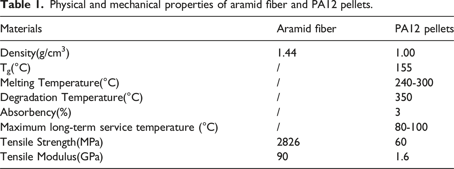
Physical and mechanical properties of aramid fiber and PA12 pellets.
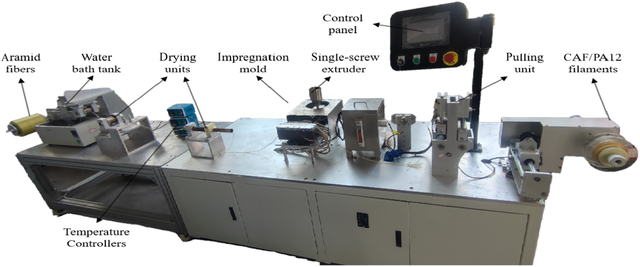
The self-designed composite filament forming equipment was used to produce CAF/PA12 filaments with a diameter of approximately 0.7 mm. The equipment mainly consisted of unwinding unit, fiber desizing unit, single-screw melt impregnation unit, traction unit and winding unit, the process schematic of which was shown in Figure 1. The water-soluble sizing agent on the surface of aramid fiber was removed and dried by fiber desizing unit; the single-screw extruder squeezed the molten resin into the impregnation mold and enabled the impregnation of aramid fiber bundle.The fiber desizing unit performed a series of processes including soaking, washing, and drying to effectively remove the sizing agent from aramid fiber bundle. After the desizing process, aramid fiber bundle was ready to be impregnated. The single screw extruder squeezed the molten PA12 pellets into the impregnation mold and effectively impregnated aramid fiber bundle. The traction unit ensured stable forming of the filaments by providing a constant traction. The final step was carried out by the winding unit, which was responsible for wound up CAF/PA12 filaments. Figure 2 presented the filament forming equipment. Schematic for manufacturing CAF/PA12 filaments. Diagram of filament forming equipment.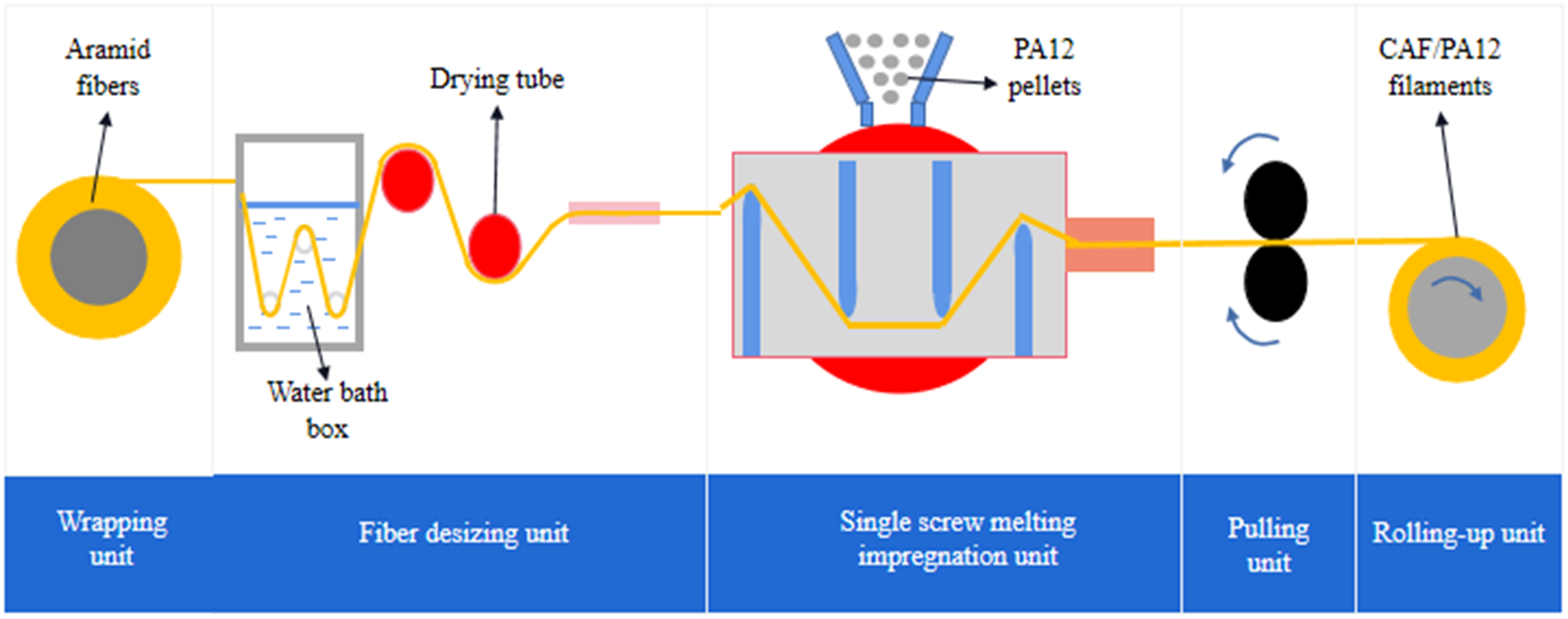
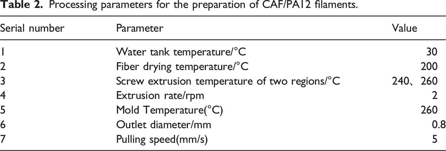
Processing parameters for the preparation of CAF/PA12 filaments.
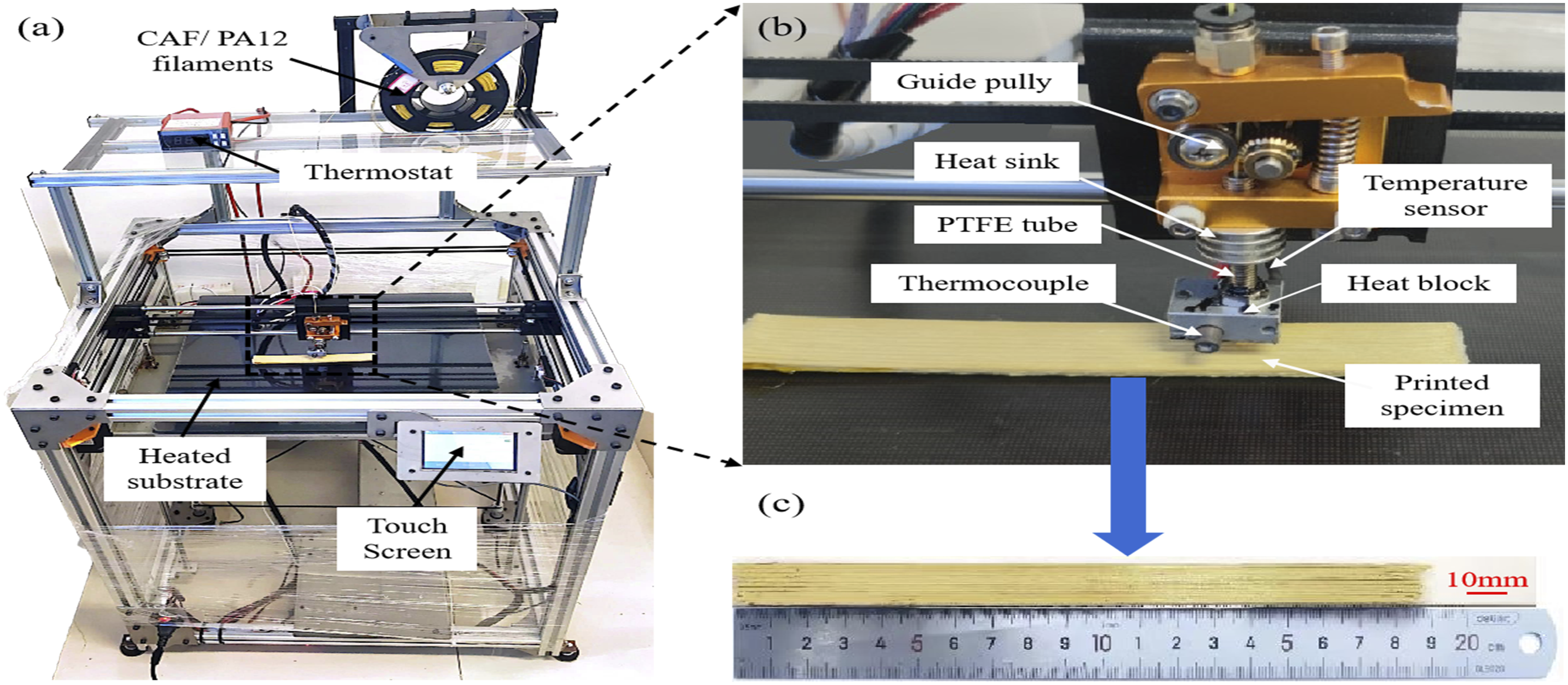
(a) 3D printer used in this study, (b) printing head, (c) 3D printed tensile specimen.
In this study, CAF/PA12 filaments were printed by a modified open-source 3D printer with the forming size of 400 mm*400 mm*450 mm in Figure 3(a). An external thermostat heater was applied to control the heating plate affixed underneath the printing substrate to meet the substrate temperature of CAF/PA12 filaments. The open source slicing software (Simplify 3D) was employed to set the printing parameters and generate the printing G-code file. According to the set printing path, the molten CAF/PA12 filaments was bonded to the heated substrate and deposited layer by layer under the driving of the printing head to complete the printing of CAF/PA12 tensile specimens.
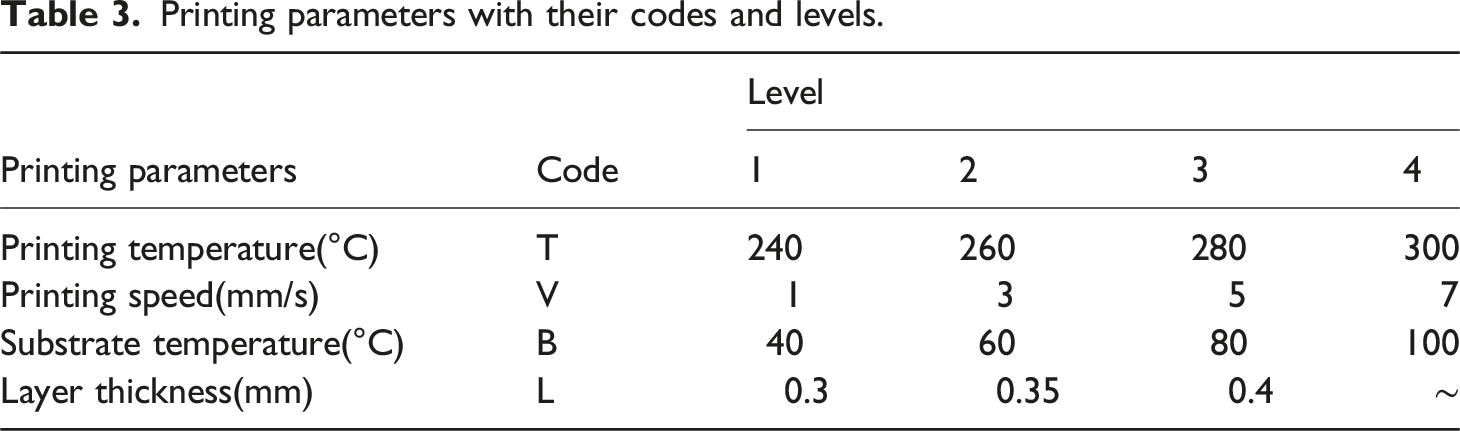
Printing parameters with their codes and levels.
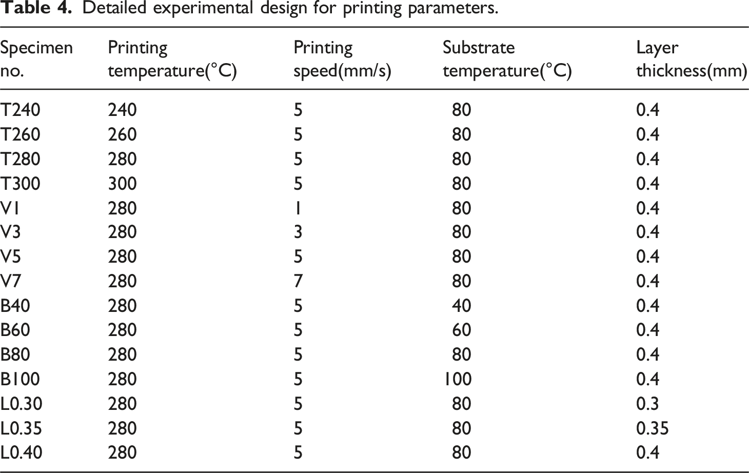
Before the tensile test, the ends of the printed tensile specimens were bonded with aluminium plates with the size of 50 mm*15 mm*1 mm to reduce the stress concentration and prevent fracture of the specimens near the clamping area, as shown in Figure 4(a). An axial hydraulic servo fatigue testing machine (MTS Landmark 370.10) was used with a displacement rate of 2 mm/min for tensile tests. The microstructure of tensile specimens was observed by scanning electron microscope (JSM-6390LV) to evaluate the quality of the impregnation and the resin/fiber interface. The specimens were sprayed with a thin layer of gold powder before the SEM observation in order to remove the charging effect for superior imaging quality. (a) Tensile specimen to be tested, (b) axial hydraulic servo fatigue tester and (c) scanning electron microscope. Detailed experimental design for printing parameters.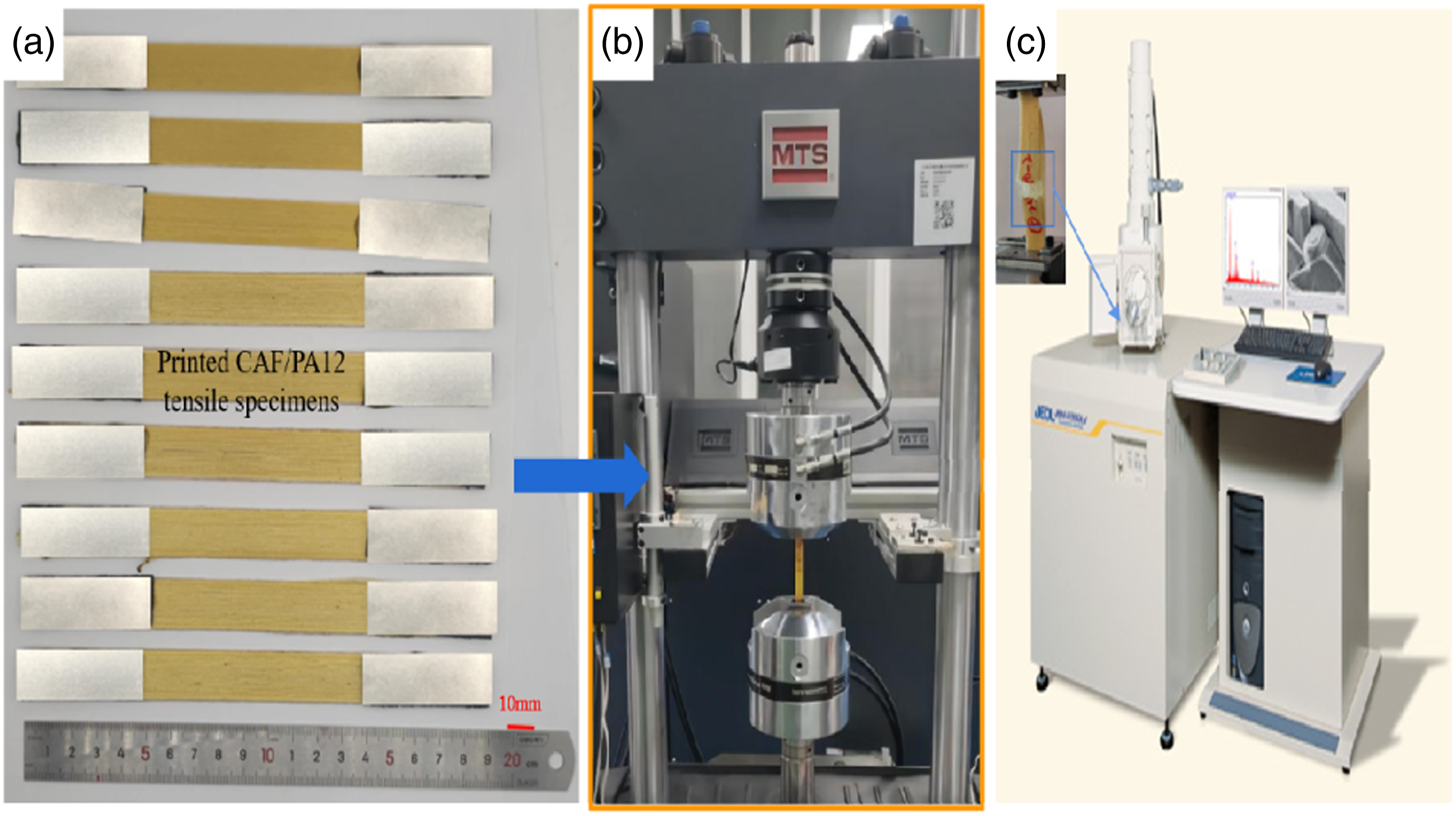
Results and discussion
Microstructure of CAF/PA12 filaments
The impregnation degree of CAF/PA12 filament was influenced by impregnation pressure and impregnation time, which in turn were closely related to screw speed and traction speed. If the screw speed was too fast, the resin content was too high. On the contrary, the resin was simply wrapped around the fiber bundle. The slower the traction speed, the higher the degree of fiber impregnation and the lower the productivity efficiency. Considering the impregnation effect and productivity, the screw speed was set to 2 r/min and the traction speed to 5 mm/s for the preparation of CAF/PA12 filaments. As saw from Table 1, the melting temperature of PA12 was 240 °C–300 °C. In this study, the mold temperature for CAF/PA12 filament preparation was set at 260°C.
The microstructure of CAF/PA12 filament observed by optical microscope (OLYMPUS, BA51 M) was shown in Figure 5. The cross-sectional area of CAF/PA12 filament estimated by ImageJ Fiji software was about 0.479 mm2. The irregular circle with larger contour was CAF/PA12 filament, the white highlights were aramid fibers, and the black colors were the voids. The distribution of aramid fibers on the cross section of CAF/PA12 filament was not uniform. Most aramid fibers were encapsulated by PA12 resin, but the fibers (red-circled area) and resin enrichment area (dark gray) were more concentrated, which suggested that the fibers had not been well impregnated. Aramid fibers were gathered near the edges of the filament surface, leaving a resin-rich area in the center of the filament, which was thought to be caused during the filament forming process. During this process, aramid fibers decreased in size as they passed through the mold exit, and aramid fibers tended to be close to the inner wall of the mold outlet as the molten PA12 was extruded into the center. Some voids were also observed in the cross section of CAF/PA12 filament, as shown in the blue area of Figure 5. These defects might be caused by factors such as insufficient mold pressure or high resin viscosity. In addition, a few air bubbles were observed at CAF/PA12 filament interface, which might be due to evaporation of PA12 moisture or incomplete drying of aramid fiber bundle interior. Cross-section diagram of CAF/PA12 filaments.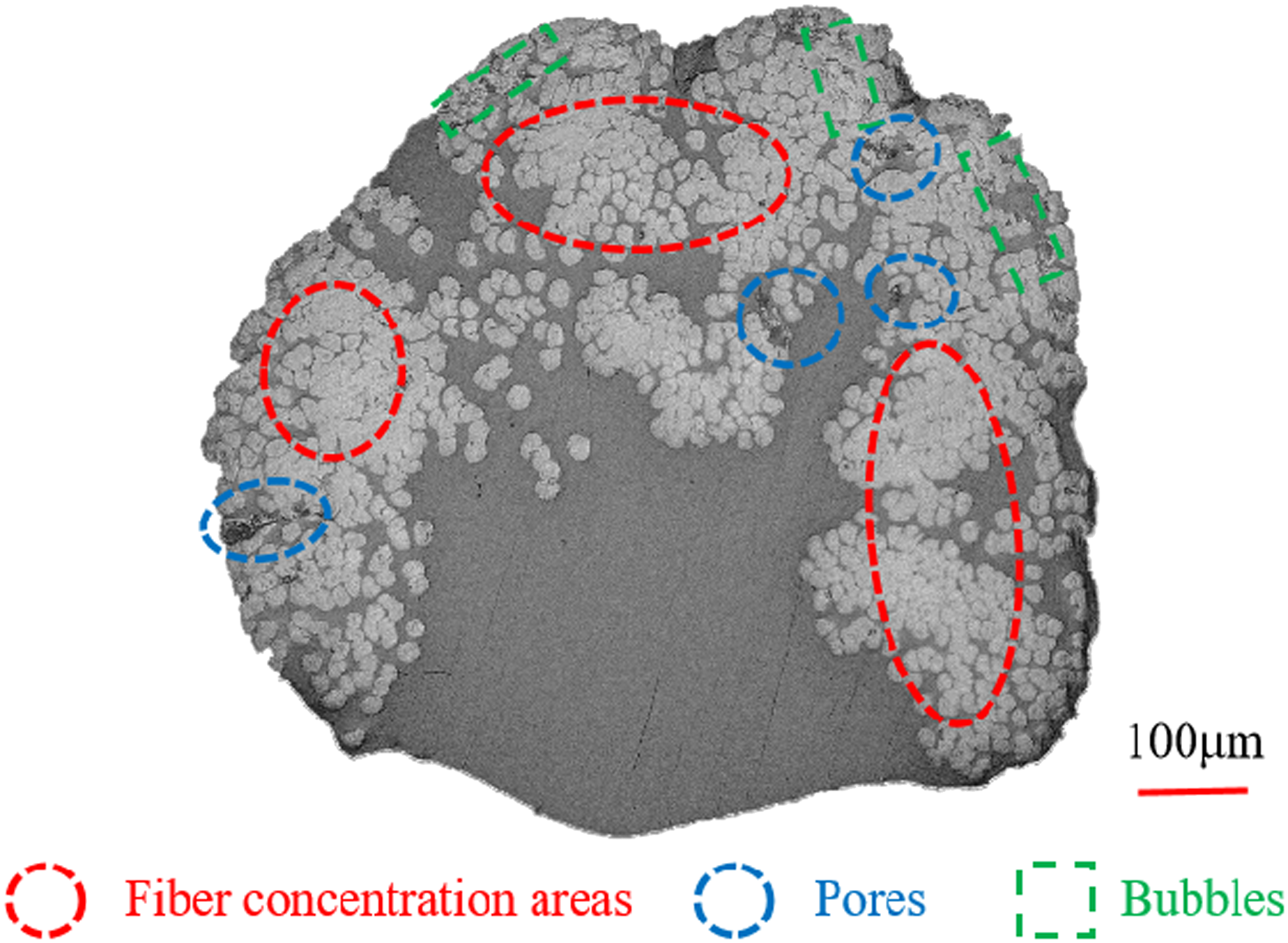
In this study, the fiber volume fraction(FVF) of printed tensile specimen was evaluated by calculating the FVF of a single unprinted CAF/PA12 filament. The total area of fibers was calculated based on the number of fibers and the diameter of the single fiber, and the FVF of unprinted CAF/PA12 filament was calculated using Equation (1).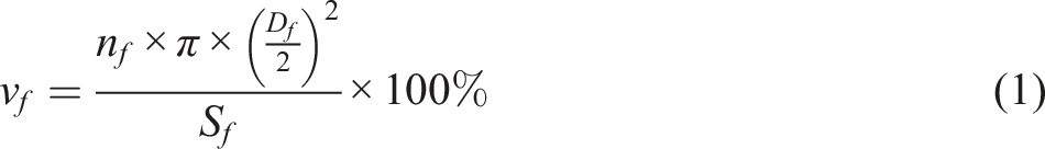
In this study, CAF/PA12 filaments were used as raw materials for printing. According to the principle of volume equality, there was a theoretical relationship between spacing, layer thickness and the diameter of unprinted filaments as shown in Equation (2). Based on the layer thickness and spacing, the number of layers(n
H
) and channels(n
W
) printed on the tensile specimen were calculated. Thus the cross-sectional area A and the FVF of printed tensile specimen were expressed by equations (3) and (4), respectively.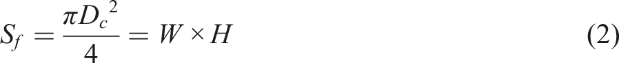

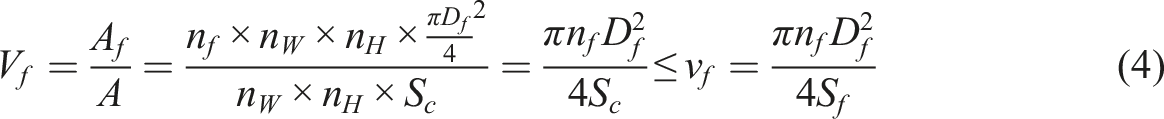
The calculated FVF of CAF/PA12 filament was 25.62%. It was worth noting that the FVF of CAF/PA12 specimen was slightly lower than that of unprinted CAF/PA12 filament. This was due to the fact that during the printing process of CAF/PA12 filament, defects such as pores were generated inside the specimen (between plies/channels), resulting in a large cross-sectional area of printed specimen. Despite the fact that the printing nozzle and the deposition between layers reduced the porosity to some extent. The FVF of defect-free unidirectional CAF/PA12 composite was equal to the filament, ignoring the voids of the filaments.
CAF/PA12 specimens tensile test results
Printing parameters played an essential part in the mechanical properties of composites. The effects of nozzle temperature (240 °C–300 °C), printing speed (1-7 mm/s), substrate temperature (40 °C–100 °C) and layer thickness (0.3-0.4 mm) on the mechanical properties of CAF/PA12 composites were studied in this paper.
As shown in Figure 6, the stress-strain curves under different printing parameters were selected to characterize the tensile property response of the printed CAF/PA12 composites. At the beginning stage of the tensile testing, aramid fibers and PA12 resin both exhibited elastic properties. At this stage, the slope of the linear part of the curve corresponded to the elastic modulus of CAF/PA12 tensile specimens. Some smaller fluctuations were observed during the gradual increasing of the tensile stress, which corresponded to fiber breakage, pullout, or interlaminar cracking. The brittle fracture led to a sharp decrease of the stress to zero as the specimens reached the maximum capacity limit, which is the maximum value of the tensile stress. Stress-strain curves of tensile specimens under different printing parameters.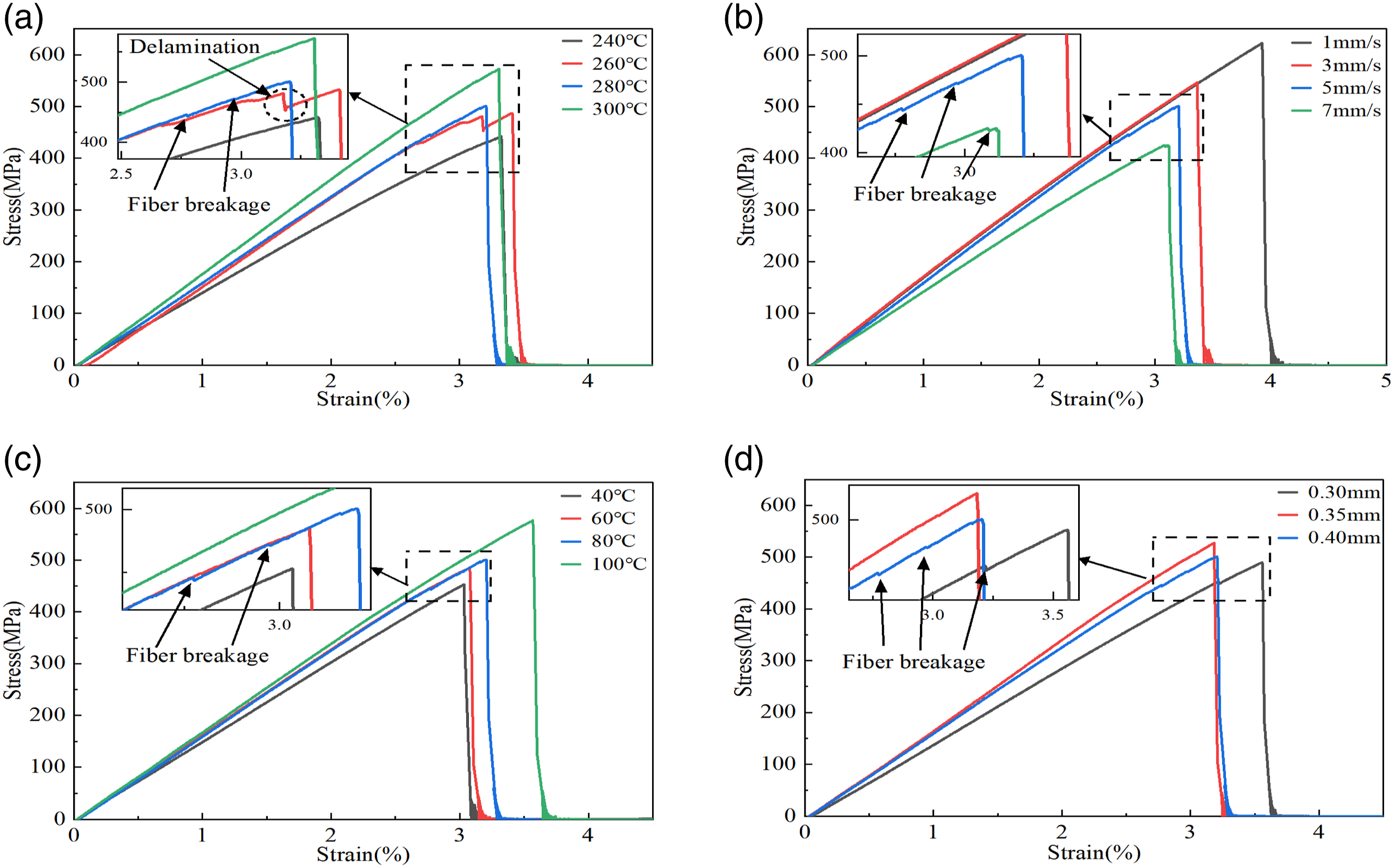
The effects of different printing parameters on the mechanical properties of CAF/PA12 printed specimens were summarized in Figure 7. As can be seen from Figure 7(a), nozzle temperature was positively correlated with the tensile properties of specimens. As nozzle temperature increases from 240°C to 300°C, the tensile strength increased from 441.81 MPa to 572.60 MPa by 29.60% and the tensile modulus from 14.63 GPa to 18.40 GPa by 25.77%. The main reason for this phenomenon was that the higher nozzle temperature reduces the viscosity of the resin,22–24 which promoted the secondary impregnation of the CAF/PA12 filament. And the increase in resin fluidity reduced void defects in CAF/PA12 specimens. Moreover, during the printing process of CAF/PA12 filaments, the enhanced aramid fibers and PA12 resin interface bonding strength and the interlayer bonding strength of composite further improved the tensile performance of the CAF/PA12 composite. Printing speed16,22–24 was also a significant factor in the mechanical properties of specimens. The tensile strength and tensile modulus of the specimen decreased by 30.03% and 24.91%, respectively, when printing speed was increased from 1 mm/s to 7 mm/s, as shown in Figure 7(b). This suggested that the lower print speed allowed CAF/PA12 filament to stay in the nozzle for a longer period of time, which promoted the secondary impregnation of CAF/PA12 filament and improved the fibers/resin interfacial bonding strength under the same conditions of other printing parameters. At the same time, the lower print speed promoted the compaction effect of the printing nozzle on the CAF/PA12 filament, which allowed the PA12 resin to penetrate into the internal unimpregnated fibers. Furthermore, longer nozzle compaction time also contributed to reduce the voids in the printed CAF/PA12 specimens and ensured inter-channel and inter-layer bonding of the specimens during the printing process, which further improved their mechanical properties. However, faster printing speeds caused incomplete melting of PA12, which negatively affected the interfacial bonding between the printed filament and the deposited composite layer. Figure 7(c) showed the tensile properties of printed CAF/PA12 specimens at different substrate temperatures. At the substrate temperature of 100°C, the maximum average tensile strength and tensile modulus increased by 13.34% and 11.90%, respectively. Layer thickness also significantly affected the interlayer bonding of printed composites.4,13,16,20,22–24 The tensile properties of printed CAF/PA12 specimens at different layer thicknesses were shown in Figure 7(d). The maximum average tensile strength and tensile modulus of CAF/PA12 specimens reached 527.35 MPa and 15.26 GPa, respectively, with layer thicknesses of 0.35 mm, which was attributed to better interlayer bonding performance at lower layer thicknesses where there was less gap between printing nozzle and the deposited layer. However, when layer thickness was too low, the molten PA12 resin was squeezed by nozzle to the outside of aramid fiber bundles; while the higher layer thickness weakened the adhesion between adjacent layers. Both of these reduced the mechanical properties of CAF/PA12 composites. Maximum average tensile strength and modulus of printed CAF/PA12 specimens at different printing parameters.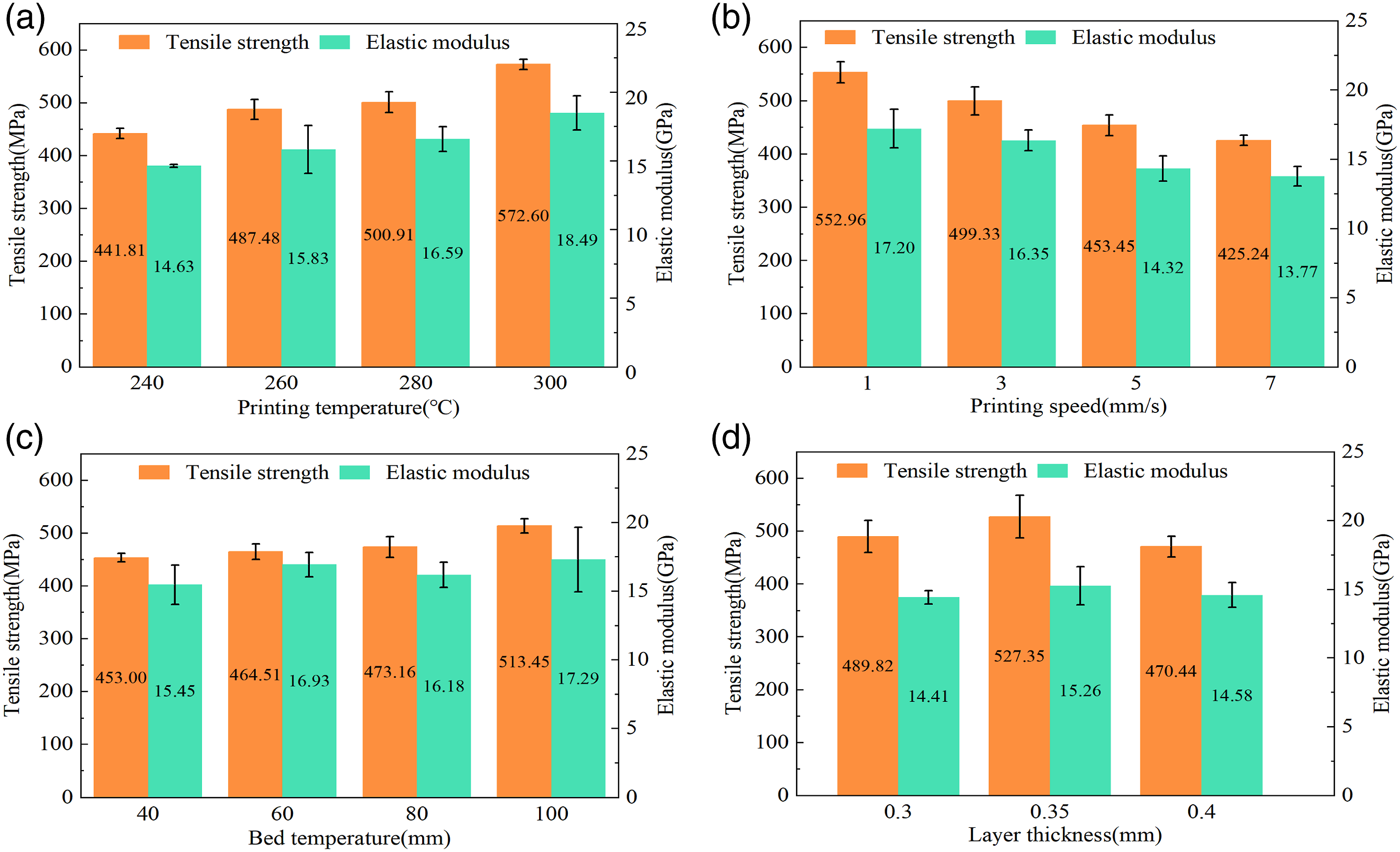
In order to accurately predict the basic mechanical properties of CAF/PA12 composites, the following basic assumptions are made: (a) The composites are all homogeneous with fibers arranged parallel and equidistant; (b) The fibers are well bonded to the matrix. In the case of stress, the strains in the composites are equal in the same direction as the fibers; (c) In the compounded state, the properties are the same as before the uncompounded state, and the matrix and fibers are isotropic. (d) There is no stress in the unidirectional composite before loading; after loading, there is no transverse stress in the fiber and matrix.


Comparison between experimental and estimated mechanical properties of CAF/PA12 composite.
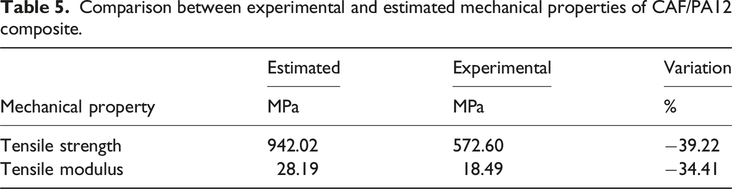
The values in Table 5 confirmed that the tensile properties of CAF/PA12 composites in the fiber direction differ significantly from the predicted properties. The difference in strength (39.22%) can be attributed to factors such as fiber bending, uneven stress distribution on the fibers, manufacturing defects, and transverse stress between the fiber and the matrix. Insufficient inter-bundle and inter-ply bonding of the composite, poor fiber-resin interface bonding, composite voids,and transverse stresses between the fibers and the resin contributed to the difference (34.41%) in stiffness of CAF/PA12 specimens.
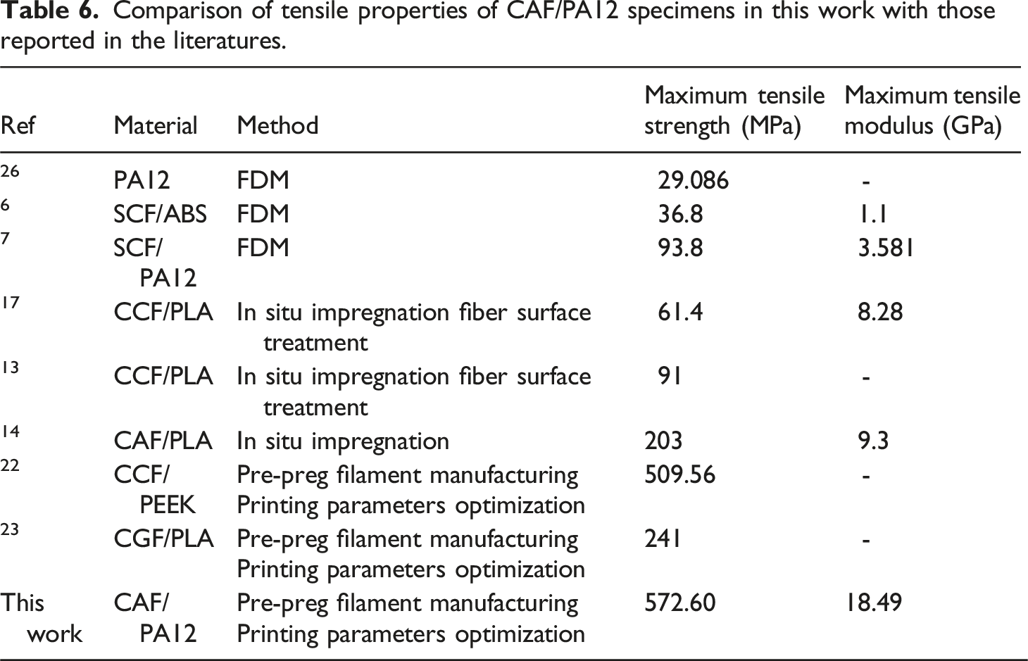
Comparison of tensile properties of CAF/PA12 specimens in this work with those reported in the literatures.
Structural analysis of cross-sections of CAF/PA12 tensile specimens
The macroscopic fracture patterns of CAF/PA12 tensile specimens with different printing parameters were illustrated in Figure 8. Filament toothed fractures indicated that the fiber/resin interface was well bonded and aramid fibers acted as a preferred load-bearing capacity, leading to superior mechanical properties. Transverse cracks could be caused by poor interfacial bonding due to inadequate bonding between adjacent filaments. When nozzle temperature was below 260°C, macroscopic damage of tensile specimen appeared as delamination. This was due to the resin had lower fluidity at low printing temperatures, resulting in poorer adhesion with printed layers during the printing process. While the macroscopic cross-sections of specimens also appeared delamination as layer thickness was 0.4 mm. However, no delamination occurred on macroscopic cross-sections for specimens in which layer thickness was less than 0.4 mm. This meant that good interlayer bonding was obtained for specimens printed at lower layer thickness and CAF/PA12 specimens showed superior tensile properties. Otherwise, there were limited differences in the failure modes of CAF/PA12 specimens' macroscopic cross-sections at different substrate temperatures and printing speeds. Macroscopic fracture failure mode of CAF/PA12 tensile specimens with different printing parameters.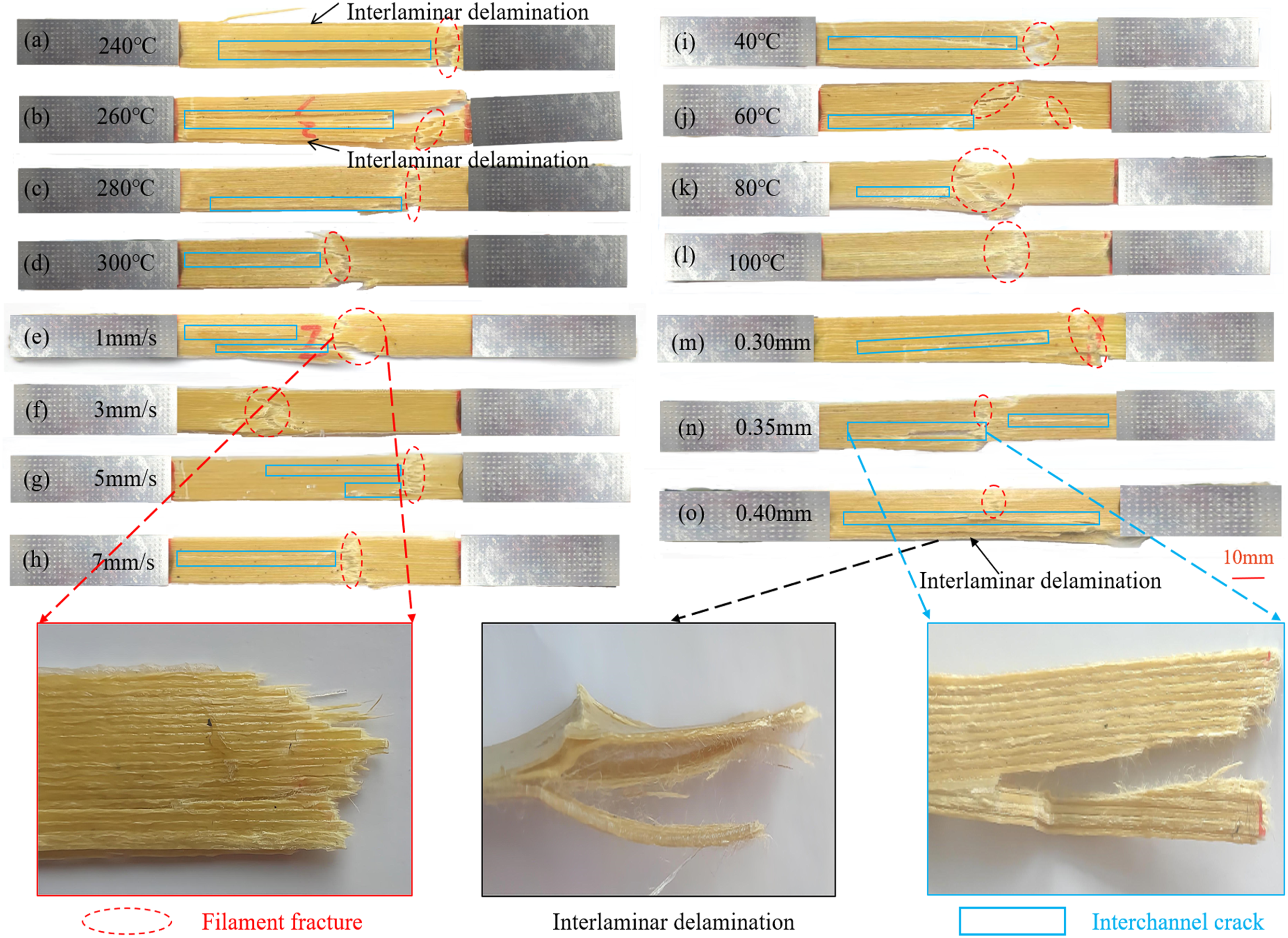
CAF/PA12 composites exhibited structural anisotropy in different directions. Figure 9 depicted the microstructural changes that occurred during the printing process of CAF/PA12 filaments. The direction of printed longitudinal tensile composite was defined as follows: the X direction represented the direction of fiber alignment, the Y direction was the transverse direction perpendicular to the X direction on the plane of the printed layers, and the normal direction of the printing layer is Z direction, as shown in Figure 9(a). Within the printed layers, it was assumed that the connection and failure between the filaments were controlled by intra-layer damage, while the layers failure was dominated by inter-layer damage. The rectangular cross-sections shown in Figure 9 were abstractions and indications of the deposited CAF/PA12 filaments, and the cross-sectional shapes here were only used for illustration. The actual cross-sectional shape of printed CAF/PA12 filament was controlled by printing parameters and tended to be an intermediate shape between rectangular and oval.[27] Microstructure changes of CAF/PA12 filament printing process.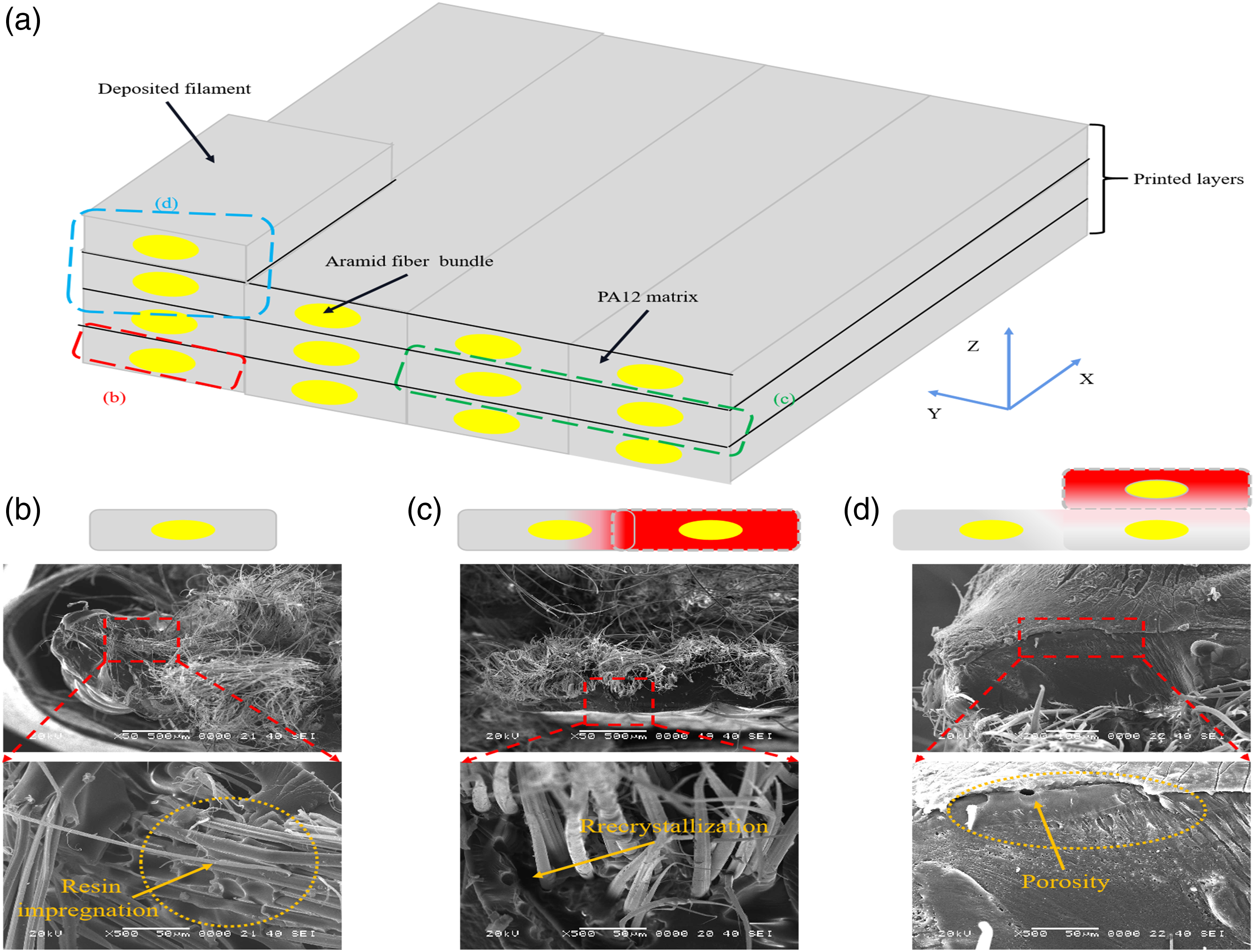
As shown in Figure 9(b), the resin has penetrated into the central region of the fiber bundle. Even after fracture, there was still adhesive resin between some protruding fibers. The spacing between two adjacent filaments was smaller than the width of the filament to ensure better connection and fusion of adjacent filaments in the printed layer along the Y direction[28], as shown in Figure 9(c).
During the filament printing process, high-temperature nozzle directly contacted the adjacent edge of the previous printed filament and heated it to the molten state. As a semi-crystalline polymer, the secondary melting and forming process of CAF/PA12 filaments were accompanied by microstructural changes. The microstructure of the transition region between two adjacent filaments was slightly different from the surrounding region due to the recrystallization in the printing layer during the bonding process.
After the printing layer was completed, the nozzle was lifted a certain thickness along the Z-axis. The nozzle would not directly contact with the printed filament of the previous layer because of the layer thickness distance. Therefore, the heat from the nozzle is transferred indirectly to the former layer through the newly extruded filament. This insufficient heat made it difficult to form a strong bonding between layers. Instead, when the new high temperature printing layer was deposited on the low temperature printed layer, it caused temperature mismatch and different cooling shrinkage, which led to the formation of pores between the layers, as shown in Figure 9(d). The presence of voids reduced the interlayer bonding strength. The failure mode was regarded as inter-layer damage. In the X and Y directions, the fracture occurred when the stress exceeds the strength of the fibers and the resin, which was considered as intra-layer damage. It should be noted that the resin strength decreased in the Y direction due to the presence of the transition zone, but was still greater than the bonding strength between the layers in the Z direction.
Microstructural observation and analysis of the fracture surfaces of CAF/PA12 tensile specimens were carried out using scanning electron microscopy in Figure 4(c) to evaluate the fiber/resin interfacial bonding properties and capture internal defects. SEM micrographs of cross-sections of CAF/PA12 tensile specimens at different printing parameters were exhibited in Figure. 11 More fibrillation was observed in the fracture cross section of CAF/PA12 specimens, which indicated that aramid fibers were effectively subjected to tensile loading. This was similar to the rather extensive fibrillation described in the literature, 15 but no fibrillation was evident in cross-sections of CCF 22 and CGF 28 reinforced composites. That could be mainly explained by the high toughness of CAF/PA12 composites, while both of the latter were brittle materials. Similarly, unimpregnated fiber pull-out was observed in some cross-sections of CAF/PA12 specimens, implying poor fiber/resin interfacial bonding.
As shown in Figure 10(a), unimpregnated fibers and fiber pull-outs were clearly observed at the fracture surface of the specimens at lower nozzle temperatures. In contrast, at nozzle temperatures of 300°C, the fracture surface of CAF/PA12 specimens appeared relatively smooth and exhibited fewer instances of fiber pull-out. This phenomenon implied that the higher printing temperature promoted the secondary impregnation of CAF/PA12 filaments. The reduction in resin viscosity improved the fiber/resin interfacial bonding strength and reduced void defects during the printing of CAF/PA12 filaments. The effect of different printing speeds on cross-sections of CAF/PA12 composites was shown in Figure 10(c) and (d). It was seen that CAF was well wrapped by PA12 resin under lower printing speed, see Figure 10(c). The degree of fibrillation in the fracture cross-section was more obvious, without excessive fiber pull-out. This phenomenon indicated that on the one hand, the lower printing speed increased the impregnation time of aramid fibers and PA12 resin in the printing nozzle, which improved the fibers/resin interfacial bonding strength; on the other hand, it increased the compaction of the printing nozzle on the filaments, which improved the bonding of the filaments between the printing channels as well as between the filaments and the already printed layer. Although the high printing speed increased the printing efficiency, it had a negative impact on the compaction effect, resulting in poor interlayer bonding. More unimpregnated fibers were seen in Figure 10(d). The cross-section of CAF/PA12 specimens showed unimpregnated fibers, fiber breakage and fiber breakage pulling out of the pores as shown in Figure 10(e) and (f). As for the effect of layer thickness, it was clearly observed from Figure 10(g) that the fractured surface was mainly characterized by fiber breakage with a layer thickness of 0.35 mm. Instead, higher or lower layer thicknesses exhibited more fibers pull-out. Microscopic images of the cross-sections of CAF/PA12 tensile specimens with different printing parameters.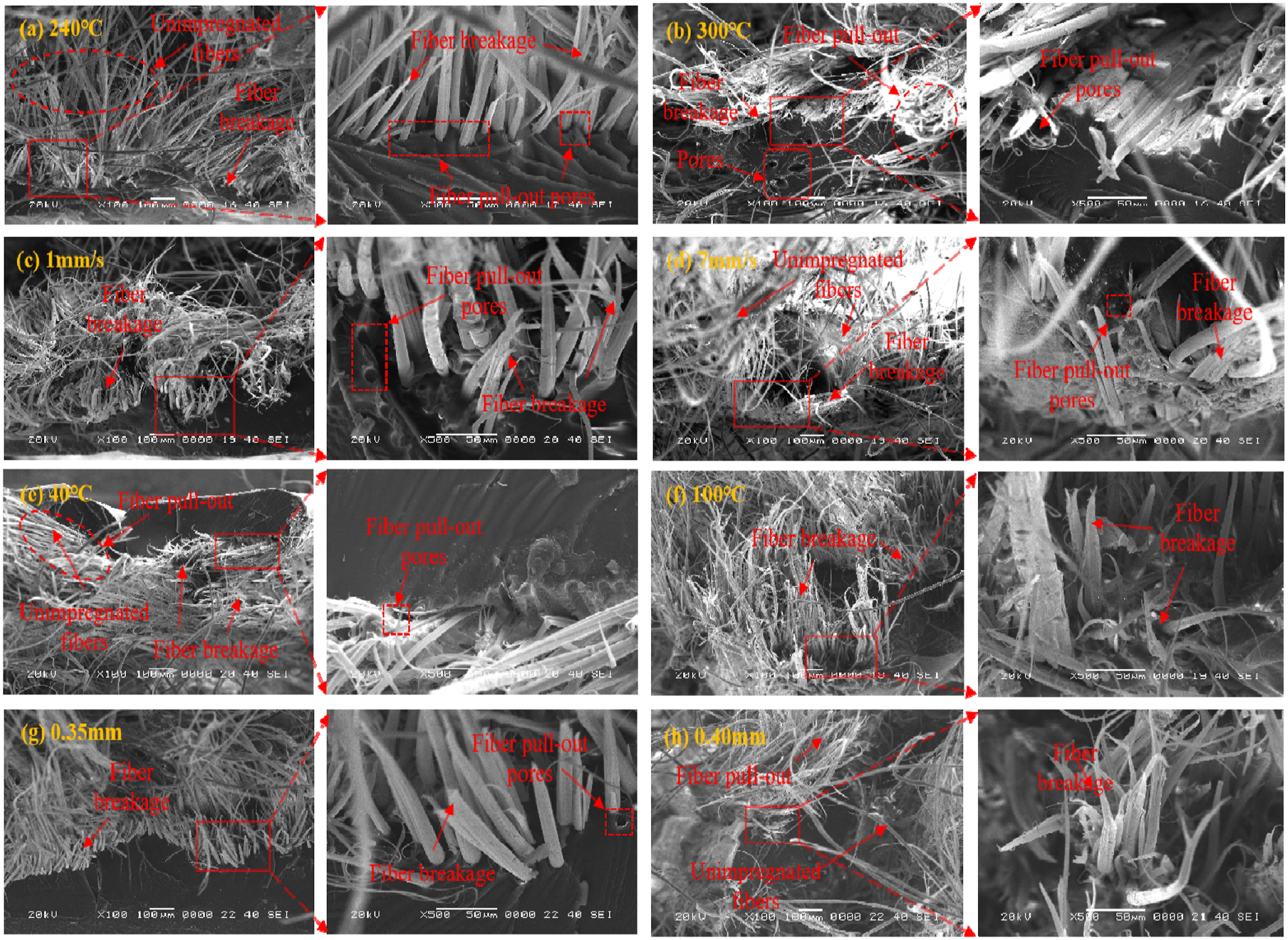
Conclusions
In this paper, CAF/PA12 pre-preg filaments were prepared by using composite filament forming equipment and a modified FFF printer was utilized to print CAF/PA12 tensile specimens. The tensile properties of printed CAF/PA12 composites were systematically investigated with different printing parameters. The conclusions are as follows: (1) The FVF of CAF/PA12 filaments was 25.62%. Insufficient mold pressure, inadequate fiber drying, and incomplete removal of water from the PA12 resin resulted in defects such as voids and bubbles inside the prepared CAF/PA12 filaments. (2) The test results of CAF/PA12 tensile specimens indicated that nozzle temperature and printing speed had a significant influence on the tensile properties of CAF/PA12 composites, while substrate temperature and layer thickness showed a minor effect. (3) The maximum average tensile strength and tensile modulus of CAF/PA12 specimens were 572.60 MPa and 18.49 GPa, respectively. Taking into account factors such as printing efficiency and time, the recommended printing parameters for this study were 300°C nozzle temperature, 3 mm/s printing speed, 100°C substrate temperature and 0.35 mm layer thickness. (4) Filament toothed fractures and transverse cracks were the main macroscopic failure modes of CAF/PA12 specimens. Microscopic failures on tensile fracture sections of CAF/PA12 specimens were mainly characterised by fiber breakage, fiber pull-out pores and unimpregnated fibers.
Footnotes
Author Contributions
Declaration of conflicting interests
The author(s) declared no potential conflicts of interest with respect to the research, authorship, and/or publication of this article.
Funding
The author(s) disclosed receipt of the following financial support for the research, authorship, and/or publication of this article: This work was supported by the National Defense Science and technology foundation strengthening plan and the Strategic Research and Consulting Project of Chinese Academy of Engineering (2021-XZ-26), the Technology Development Fund of China Academy of Machinery Science and Technology (332202Q9), and National Key Research and Development Program of China (2023YFB4605302)