
Abstract
Research shows that mechanical properties of parts produced using fused deposition modeling (FDM) are inferior when compared to parts produced using conventional techniques such as injection molding. Efforts have been made in recent years to improve mechanical properties by reinforcing the parts with high strength fibers. This has been achieved by either modifying FDM setups to extrude fibers with thermoplastics and fabricate continuous fiber reinforced thermoplastic composites (CFRTPCs) or employing manual techniques subsequent to part production. Existing CFRTPCs fabrication procedures have limitations of fiber exposure to environment, no direct control method for volume fraction, and poor surface finish. This research work is focused on improving the process of producing CFRTPCs by addressing these limitations using a dual extruder FDM setup. The process developed was tested for its feasibility using Kevlar fiber as reinforcement for commercially available ABS, PLA, PLA-C, and PLA-Cu thermoplastic fibers. Taguchi L16 orthogonal array was used to design experiments, while tensile and flexural testing was performed to determine mechanical properties achieved. Tensile strength was improved up to 3 times the baseline value of thermoplastics, while flexural strength was improved up to 1.6 times. This technique can further the goal of developing CFRTPCs, on industrial level, using FDM with better control over volume fraction and fiber layup.
Keywords
Introduction
Manufacturing technologies can be broadly categorized as formative, subtractive, or additive. 1 Additive manufacturing (AM) is a modern-day technique which outshines conventional manufacturing technologies, subtractive and forming alike, in that this technique is less time-consuming, highly flexible, fully automated, and produces nearly zero waste. AM can be used for metals, ceramics, polymers (liquid or filament), composites (polymers with natural/synthetic fibers), and alloys. However, a single system cannot be utilized for all, as a specific set of parameters and conditions are required for each material category. Figure 1 shows the most relevant classification for AM techniques. 2 This research aims at fused deposition modeling (FDM) that is a type of solid-based AM system.
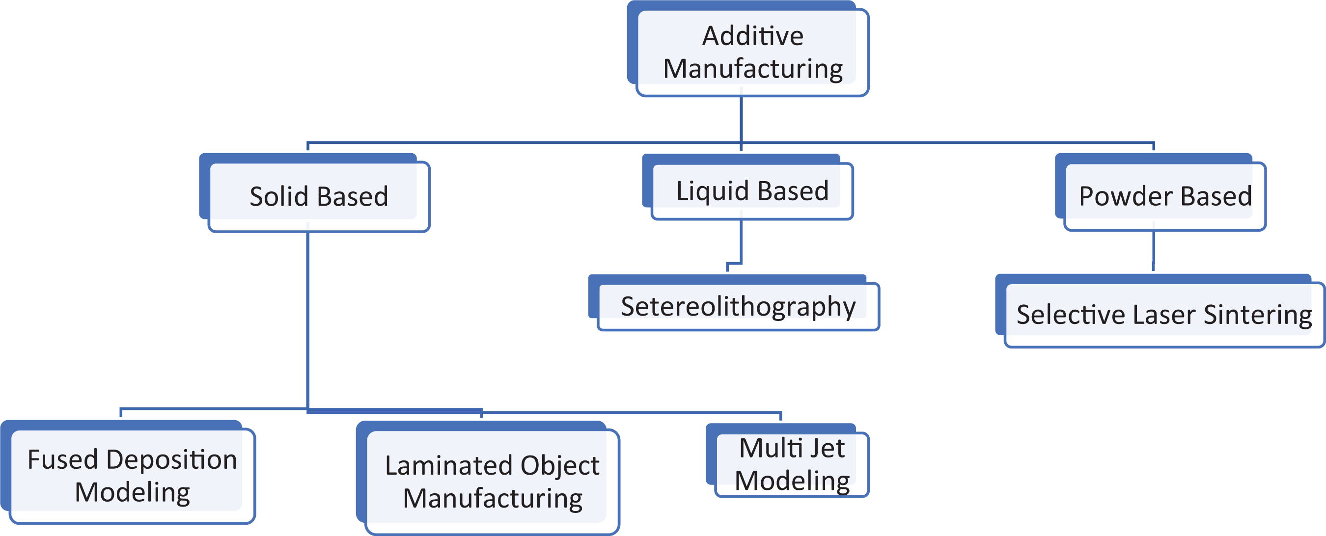
Categories of additive manufacturing. 2
FDM is the most common technique of AM being used in industry due to its low material and machine cost, low operating temperature, reasonably reduced part production time, and high process accuracy.3,4 In this technique, fused thermoplastic is deposited layer by layer through a heated nozzle assembly to form a part according to the input Computer Aided Designmodel. 5 Here strength of the part becomes function of bonding between consecutive layers. This bonding is limited due to the complex thermal cycle of the process. 6 Therefore, strength of a part fabricated using FDM is much lower than the strength of a part fabricated through conventional techniques such as injection molding. This limits the utilization of FDM to prototyping instead of serial manufacturing in the industry. In recent years, improving mechanical properties of parts produced by FDM has been a prime focus of research. Studies performed can be primarily categorized into 03 groups.
Thermoplastics
Studies have shown that using FDM for parts production is an optimization problem for the involved parameters. Effect of raster angle/width/gap, layer thickness, and part orientation on stiffness and mechanical properties of fabricated parts has been investigated in detail.4,7,8 Similarly, effect of material type, part build orientation, and feed rate on mechanical properties of the fabricated parts has also been analyzed in depth.9–11 Processing time and material consumption rate for different thermoplastics has also been investigated. 12 Part fabrication using two different thermoplastics has also been investigated in detail. 13
Even though authors have optimized the parameters, the outcome mechanical properties remained lower than corresponding properties for parts produced using conventional techniques such as injection molding. These inferior mechanical properties limit the use of parts produced using FDM to only prototypes for “proof of design concept.” Functional parts require superior mechanical characteristics; therefore, the use of conventional techniques is preferred over FDM.
Short fiber reinforced thermoplastic materials
Over the past two decades, manufacturing of short fiber reinforced thermoplastic using conventional technique and then converting it to stock filament form for utilization in FDM machines to improve mechanical characteristics of thermoplastics has also been investigated, for example, feasibility of using short glass fiber (GF) reinforced ABS instead of pure ABS for FDM process. 14 It was found to improve strength of ABS; however, addition of GF reduced flexibility and handleability of ABS, thus the composite could not be formed into filament rolls and improvement was obtained by adding compatibilizer and plasticizers. GF-ABS exhibited better mechanical properties compared to pure ABS. ABS filament blends for FDM with titanium dioxide, jute, and thermoplastic elastomer (TPE) have also been investigated 15 with tensile strength and Scanning Electron Microscope (SEM) analysis.
Effects of FDM machine parameters on the print quality of short carbon fiber (SCF)-ABS filament with 5 wt% have also been investigated. 16 Subsequently, further research with graphite-ABS as stock materials for FDM printing of samples with the same composition has been performed. 5 This has been followed up by a comparison of both research. 5 Authors identified that SCF-ABS samples exhibit better tensile properties; however, inherent porosity in SCF-ABS is much larger than graphite-ABS. Similarly, impact of nozzle temperature and infill orientation on SCF-PLA parts has also been studied and compared with PLA. 17 Authors have found that both parameters significantly impact part strength with addition of SCF yielding better properties than pure PLA. However, the parts fabricated have been annealed prior to testing, which may significantly enhance mechanical characteristics as stresses induced due to FDM process will be relieved.
Researchers have also investigated the possibility of using immiscible plastics for single part production. 18 Impact on tensile strength for parts produced using SCF-PLA with ABS has been investigated for this purpose. Authors have ascertained improved tensile properties with significant effect of layer height and printing speed. However, immiscibility plays a critical role in failure pattern which requires further investigation.
Continuous fiber reinforced thermoplastic composites (CFRTPCs)
A more useful but uncommon technique is fabricating high strength parts using continuous fiber reinforcement instead of short fiber with a polymer resin. Conventional fabrication facilities for CFRTPCs have a very steep operating and setup cost. Researchers have been successful in modifying FDM setups to fabricate high strength unidirectional composite parts.19–23 Mechanical testing (tensile strength, flexural strength, and interlaminar shear strength) has shown properties to enhance two to five times than the baseline thermoplastics. However, SEM analysis shows further potential in strength enhancement if the voids generated due to presence of fiber can be controlled, which has also been experimentally proven. 20 This technique eliminates the need of forming complex molds for fabrication of CFRTPCs with complex curved shapes. The term of Composite 2.0 for CFRTPCs printed using AM technology has also been coined. 21 Another technique for improving mechanical properties of thermo-polymers is to only add high strength fiber reinforcement to the main load bearing path. 24 However, this method involves manual labor and subsequent part curing to overlay the reinforcement on the polymer part produced from AM techniques.
Similarly, commercial FDM filament producers have begun providing continuous fibers infused with nylon. These are available in filament form and can be used to produce parts using FDM setups. Results of tensile and bending tests conducted for nylon with carbon, glass, and Kevlar fiber composites have been reported.25–27 The filaments are currently only available as composites of nylon with carbon, glass, and Kevlar fiber. Therefore, the process does not afford the flexibility to fabricate any combination of fiber and matrix other than the aforementioned materials.
Albeit the many advantages of this improvement in FDM process, part building process becomes slower as compared to fabricating a plastic part. The advantage of superior part surface finish is lost using this technique as larger diameter nozzles are used. Also, as the thread is exposed to environment, deterioration may also set in overtime which would degrade the mechanical properties of the structure. 28 Also, there is no direct method of controlling the volume fraction of parts produced; researchers have tried managing it by modifying the flow rate of thermoplastic.
Therefore, this study aims at an attempt of devising a novel technique which will provide better control over volume fraction, protect the high strength fiber, and afford the flexibility to only lay reinforcing fiber at desired places in the composite fabricated using FDM. A dual extruder FDM setup was utilized where one small-sized nozzle prints thermoplastic shell to provide good surface finish and protection to fiber from environmental effect, while the other large-sized nozzle is modified to make it capable of extruding high strength fiber along with fused thermoplastic resulting in better mechanical characteristics. Proposed technique has the potential to enhance the acceptability of FDM in manufacturing industry. The established technique can produce any shape while the flexibility of producing small intricate features remains intact. Subsequently, technique has been validated by enhancing the mechanical properties of thermoplastics fabricated using Kevlar (para-aramid) fiber as reinforcement.
Methodology
Equipment and material selection
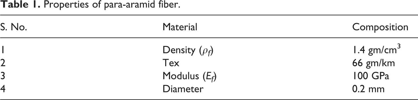
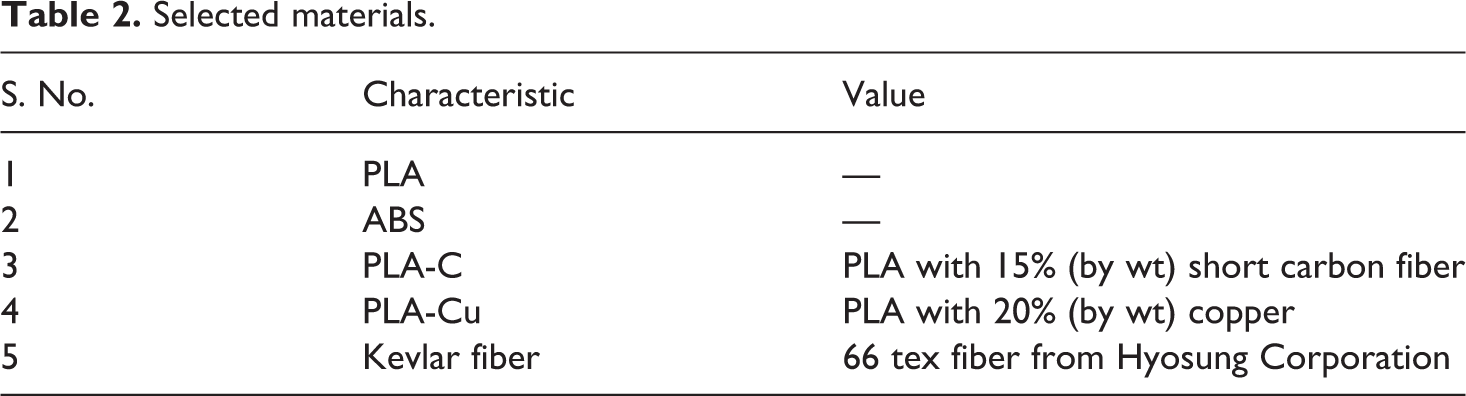
Commercially available dual extruder FDM setup from Shenzhen Anet Technology Co. was used for this research. A few important fiber properties which have been directly used during calculations of the composite properties are listed in Table 1. Table 2 provides brief detail of the materials procured for the purpose of this research.
Properties of para-aramid fiber.
Selected materials.
To evaluate the mechanical properties of the CFRTPCs fabricated, SHIMADZU AGS-X Series UTM was used with a 20 kN load cell for tensile testing and three-point bending test.
Modification of FDM setup
Two approaches were selected for investigation, initially the thread was inserted in same slot designed for inserting thermoplastic filament in hot-end as shown in Figure 2. If this approach failed or the thread got damaged due to friction force exerted by the moving of thermoplastic filament, nozzle modification was planned as shown in Figure 3. The first approach proved fruitful without affecting fiber; however, a large friction force was exerted on the fiber. Therefore, nozzle assembly was modified by simply drilling a hole at approximately 40° angle (Figure 3). The fiber flowed easily through this hole along with the molten thermoplastic. Results achieved for both techniques, physical part and mechanical properties, were identical. Therefore, both techniques were successfully established and can be used effectively. It may be noted here that a two-nozzle system was utilized and modification in only one nozzle was performed to accommodate high strength fiber, while the other nozzle was kept in its stock form for extruding pure thermoplastic.
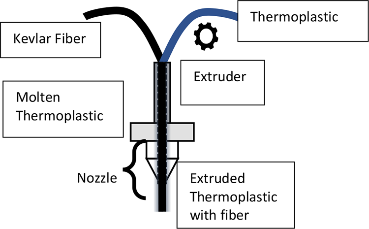
Nozzle schematic for fiber in hot-end slot for thermoplastic.
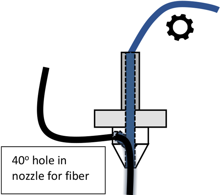
Nozzle schematic with proposed modification for fiber.
Novel technique
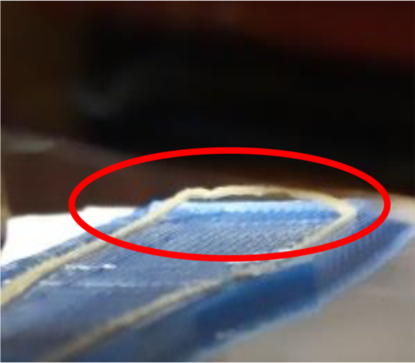
Experiments were carried out to establish the feasibility of the modification. The selection of parameter settings was based upon previous investigations and their impact on mechanical properties of the parts. Infill speed was kept low because the thread begins to pull out of the thermoplastic at higher speed as shown in Figure 4. The same phenomena was also observed for fiber turn of greater than 90° angles. This was a regeneration of the prior research available on printing CFRTPCs using FDM.19–23 All these research utilized a single-nozzle extrusion system, which implied that fiber and matrix were extruded together as long as the part was being fabricated. Therefore, the matrix and fiber can only be deposited in the similar direction, the fiber was exposed to atmosphere, volume fraction would have no direct control mechanism, and the part surface finish would be affected due to use of large-sized nozzle.
Thread pull out at faster print speeds.
The premise of this research was to address the aforementioned limitations. A new procedure was devised such that instead of using a single extruder system, a dual extruder system was utilized. With one nozzle being used to print fiber–matrix combination while the other nozzle only printed thermoplastic. This combination afforded the flexibility of printing high strength fiber as and when required; the direction of pure thermoplastic printing was independent of the fiber–matrix combination printing and a shell protecting high strength fiber could be printed. Figure 5 shows the design of fiber layer that were simulated in software prior to part fabrication. Here it can also be seen that pure thermoplastic (shown in green) has different print path than the fiber–matrix combination. Additionally, printing pure thermoplastic shell with a small-sized nozzle improved the part surface finish drastically. Figure 6 shows a layer of fiber being laid over pure thermoplastic shell. Successful trial runs were carried out to fabricate the parts with different fiber orientations at desired specimen heights. However, compatible software had limitation of only printing the infill at a single location. This limitation was overcome by understanding the G-code being generated by the software and modifying it to so that fiber can be printed in any layer of the sample of any shape. This novel technique has following advantages over the previous CFRTPCs fabricating technique: Direct and improved control over volume fraction of fabricated parts, Protection of high strength fiber from environmental impact, Better surface finish while maintaining flexibility of printing smaller features, Printing of high strength fiber at desired places only.
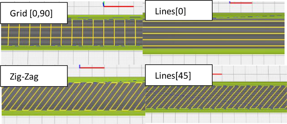
Few achievable infill designs.
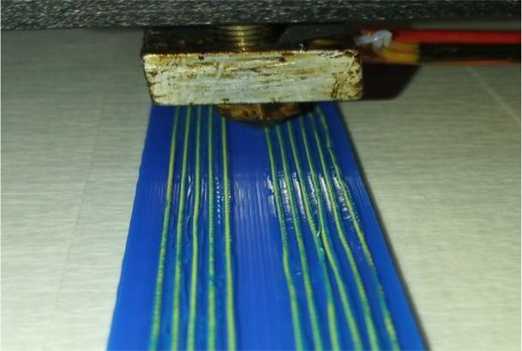
Printing fiber layer.
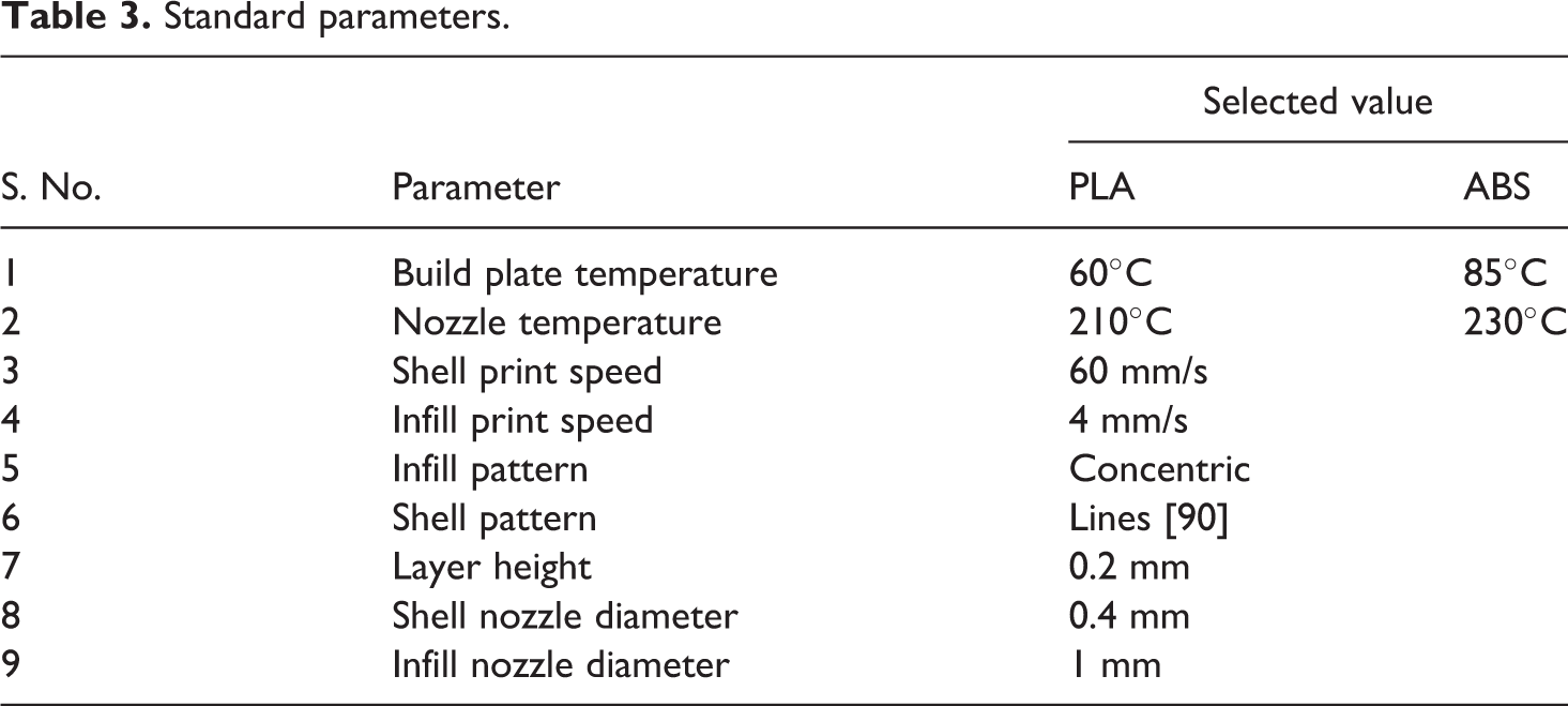
Subsequent to successful fabrication of parts using this novel technique, standard specimen according to ASTM standards was manufactured and tested to validate improvement in mechanical characteristics. Standard parameters used are listed in Table 3; these parameters were kept constant throughout the experimentation and validation.
Standard parameters.
Validation design of experiment (DOE)
Taguchi DOE was used for designing experiment to study the impact of this CFRTPCs fabrication technique. Taguchi DOE yields two primary benefits, it is a systematic technique of exploring possible system configurations especially helpful when complex problems are being investigated and it provides a means to investigate possible alternatives cost-effectively.29,30
ASTM standards and specimen design
ASTM standards were used to develop specimens.31–34 Specimen dimensions and design are shown in Figure 7. Smaller part with the specimen represents the nozzle priming area. The purpose of this part was to provide a place where the shift between nozzle can be encoded. This priming area was also used as the location for cutting off fiber once fiber lay up in a layer had been completed. Standard specimen testing speeds (5 mm/min for plastic samples for both tensile and flexural testing, 2 mm/min for tensile and 1 mm/min for flexural testing of composite samples) were selected for each sample type according to relevant ASTM standard.
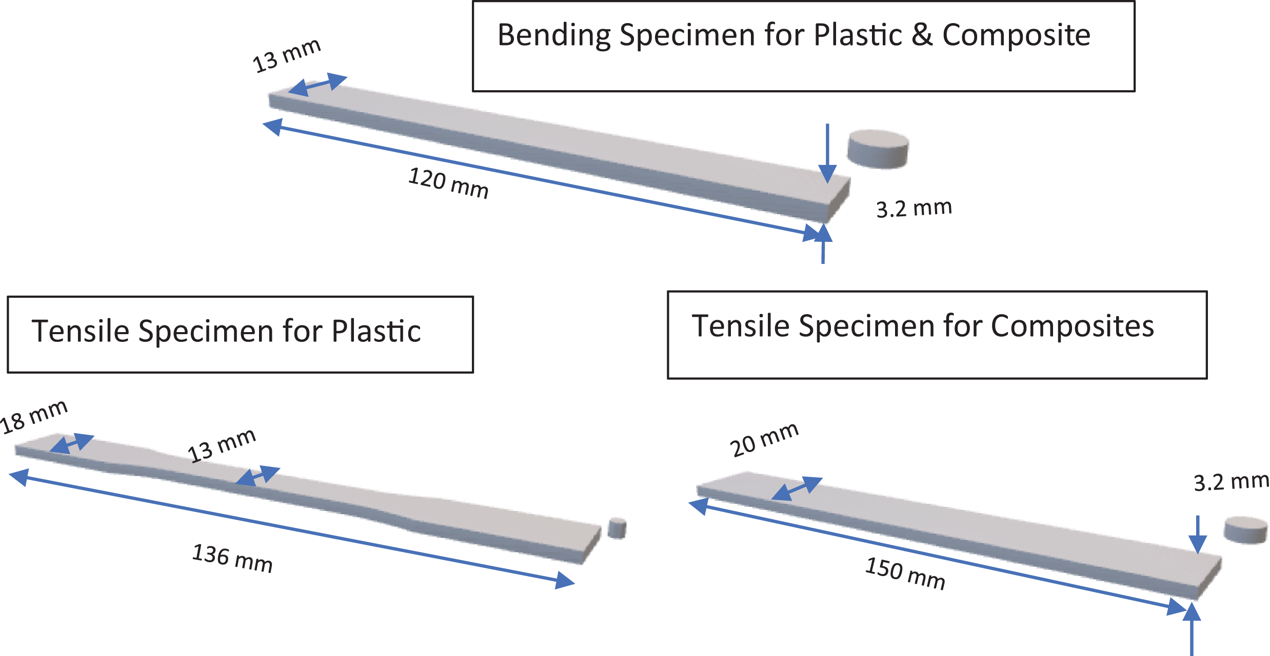
Specimens with dimensions.
Selection of parameters for validation
Four materials were selected to perform a comprehensive study on their properties and interaction with para-aramid fiber. Number of fiber layers were also considered for this study to ascertain optimum level of fiber. During literature review, it was found that there was pronounced void formation in parts produced using FDM printing of CFRTPCs due to lack of bonding between successive layers. 19 Thus, a hypothesis was formed to test the improvement of part strength by printing fiber-reinforced layers with thermoplastic layers between them. This may inhibit void formation due to less cooling time, as the printing speed for pure thermoplastic layers was faster than for fiber layers. Successful implementation of this step also required extensive modification of each G-code file. This parameter has been named as “layer gap.”
Layer design for fiber deposition was carried out with wall thickness just enough to avoid thread exposure. Bending specimen has smaller cross-section; therefore, it was used to determine maximum possible tows. This resulted in a maximum of 12 tows per layer of fiber with a wall thickness just enough to shelter the fiber as shown in Figure 8. Therefore, one layer of fiber is equivalent to 12 fiber tows, here on referred as “thread count.” The same number of fiber tows was also utilized to design tensile specimen.
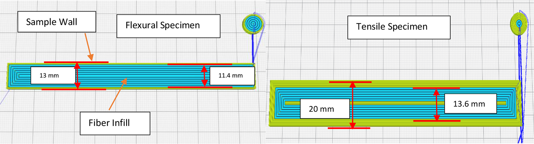
Fiber layer design.
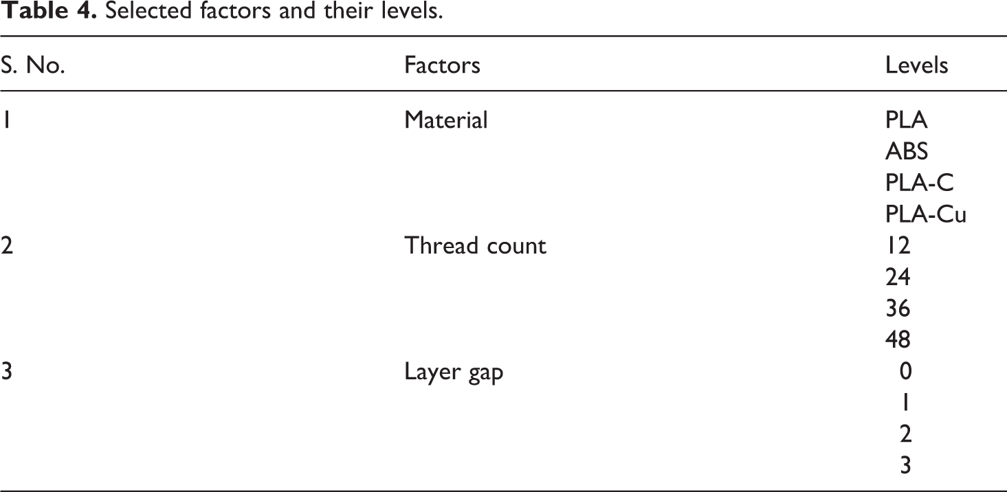
Figure 9 is a graphical representation comparing combination of “number of fiber layers” with “layer gap” that can be achieved. With single layer height fixed at 0.2 mm, a maximum of 16 layers constitute a single sample. This is the point where the red line crosses x and y-axis on the shown graph. It can be deduced from this representation that with thread count beyond 48, layer gap begins to reduce. Therefore, combination beyond four layers of fiber (48 threads) cannot be explored. The same is highlighted by “X” marked on the graph at 48 thread count with 03 layer gap. Height of the sample in millimeters and number of fiber layers across the specimen cross-section are also shown here for ease of reference. Factors selected, along with factor levels, for validation part of this research are presented in Table 4. The selection is based upon the discussed system limits where maximum combination is 48 thread count with 03 layer gap. Values achievable below this combination have been utilized.
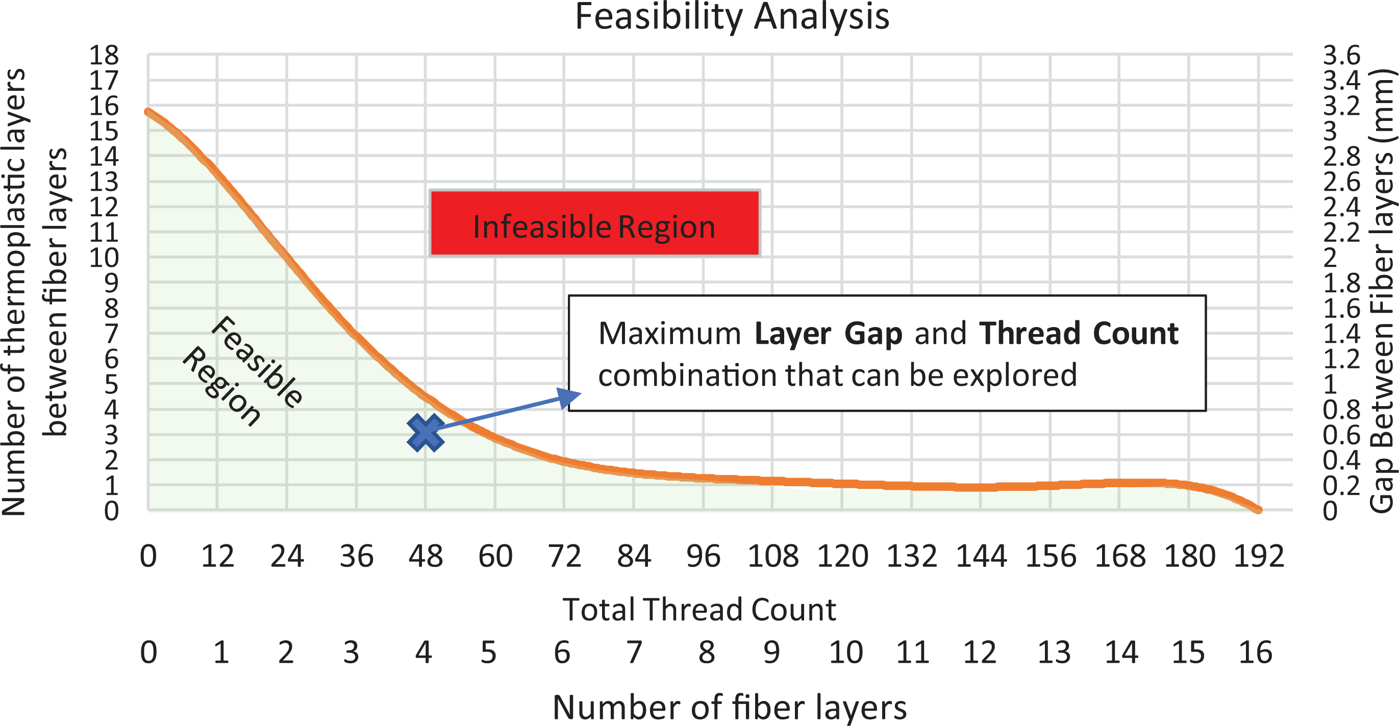
Feasibility analysis.
Selected factors and their levels.
Orthogonal array (OA) modified L16 was selected as it met all the conditions for Taguchi DOE. The selection of L16 OA reduced number of experiments from total of 256 for full factorial, including 02 repetitions for each setting, to a total of 64 with generation of same information. It was also decided to perform more trial runs for the array that generates results with a difference of more than 10% among each other for tensile as well as flexural testing.
Following must be mentioned here for the handling of special conditions: Number of threads was used instead of using number of layers to accommodate settings such as 12 threads with 03 layer gap. In such instances, the number of threads was divided into 02 layers with 06 threads each and printed at the layer gap against the setting. G-code generated for each setting was modified according to experimental requirements, while code for each setting was made separately with 02 samples (both bending or both tensile) for each setting being printed together. Taguchi DOE is essentially a fractional factorial design. Therefore, it may be necessary to perform confirmatory experiments on the optimized settings subsequent to analysis.
Volume fraction estimation
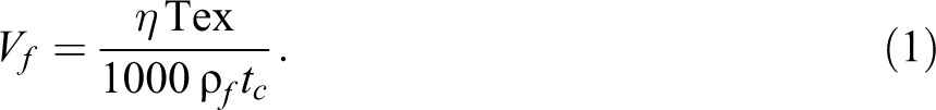
Polymer matrix composites (PMCs) are produced as a combination of amount of fiber and matrix, represented by fiber and matrix volume fraction. 28 The fiber volume fraction Vf can be calculated analytically if the material properties are known using equation (1).
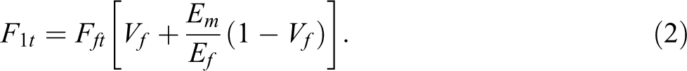
For tensile strength F1t of the composite laminate containing unidirectional fibers, rule of mixtures (ROMs) equation can be used for theoretical prediction. ROM equation is as stated in equation (2).
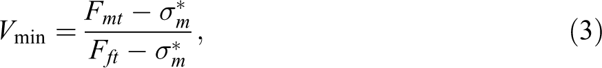
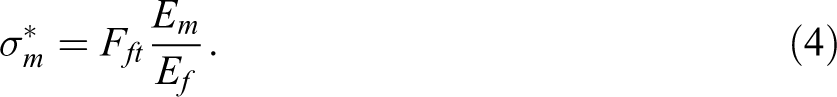
Minimum volume fraction, Vmin, was estimated by relationships as shown in equations (3) and (4).
Volume fraction was estimated using equation (1) for flexural as well as tensile samples, while equation (2) was used for theoretical estimation of the tensile strength. For predicting flexural strength, no such analytical formulas exist. Hence, reliance is made on experimental data for determination of flexural properties. Summary of the results achieved for each material type with only one enforce layer are listed in Table 5, here material with prefix “E” indicates enforced material. Strengths are in “MPa” and volume fractions are in absolute values.
Vmin for all materials.
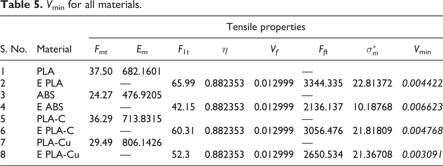
Vf computed in the table is volume fraction achieved for a single layer. The explored Vf ranges from 1.3% for one layer to 5.2% for 04 layers (48 thread count) of fiber, which is above the Vmin value. Hence, it was safe to conclude that strength should improve. Calculations further revealed that max volume fraction for the current design of specimen becomes 18% for tensile sample and 21% for flexural sample.
Results and analysis
Mechanical properties of thermoplastics
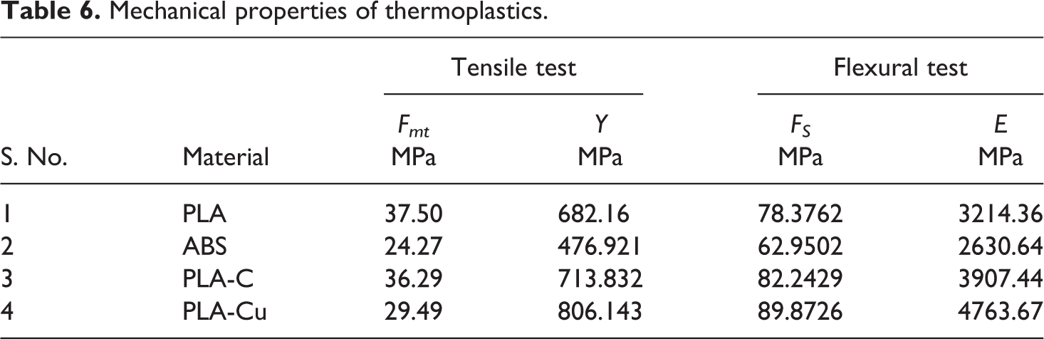
Thermoplastic samples according to ASTM standard were fabricated to develop the baseline and provide a comparison. Figure 10 shows sample under tensile and three-point bending tests. Testing was continued till specimen failure so that fracture analysis can be performed subsequently. Table 6 provides a summary of the properties achieved. Here it must be noted that the values achieved were close to the values available in literature reaffirming the quality of the materials used.4,10,11,15,23
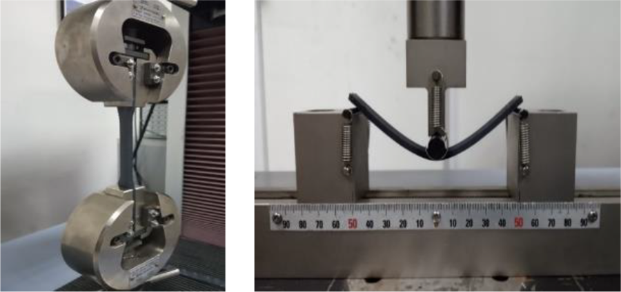
Tensile and flexural testing.
Mechanical properties of thermoplastics.
Mechanical properties for the Kevlar reinforced thermoplastics
Subsequently, G-codes for all the settings according to the selected OA were generated and samples were printed at random. Table 7 provides summary of test results for tensile and flexural testing of the samples tabulated using Minitab® software. For the purpose of providing a good comparison, equation (2) was used to estimate tensile strength theoretically. In close agreement to theory, 28 predicted strength was far greater at each setting than achieved strength. Fft calculations presented in Table 5 were reused here to estimate the theoretical tensile strength of composites. This is the only reason that the predicted strength is same at the lowest volume fraction.
Mechanical properties of reinforced thermoplastic.
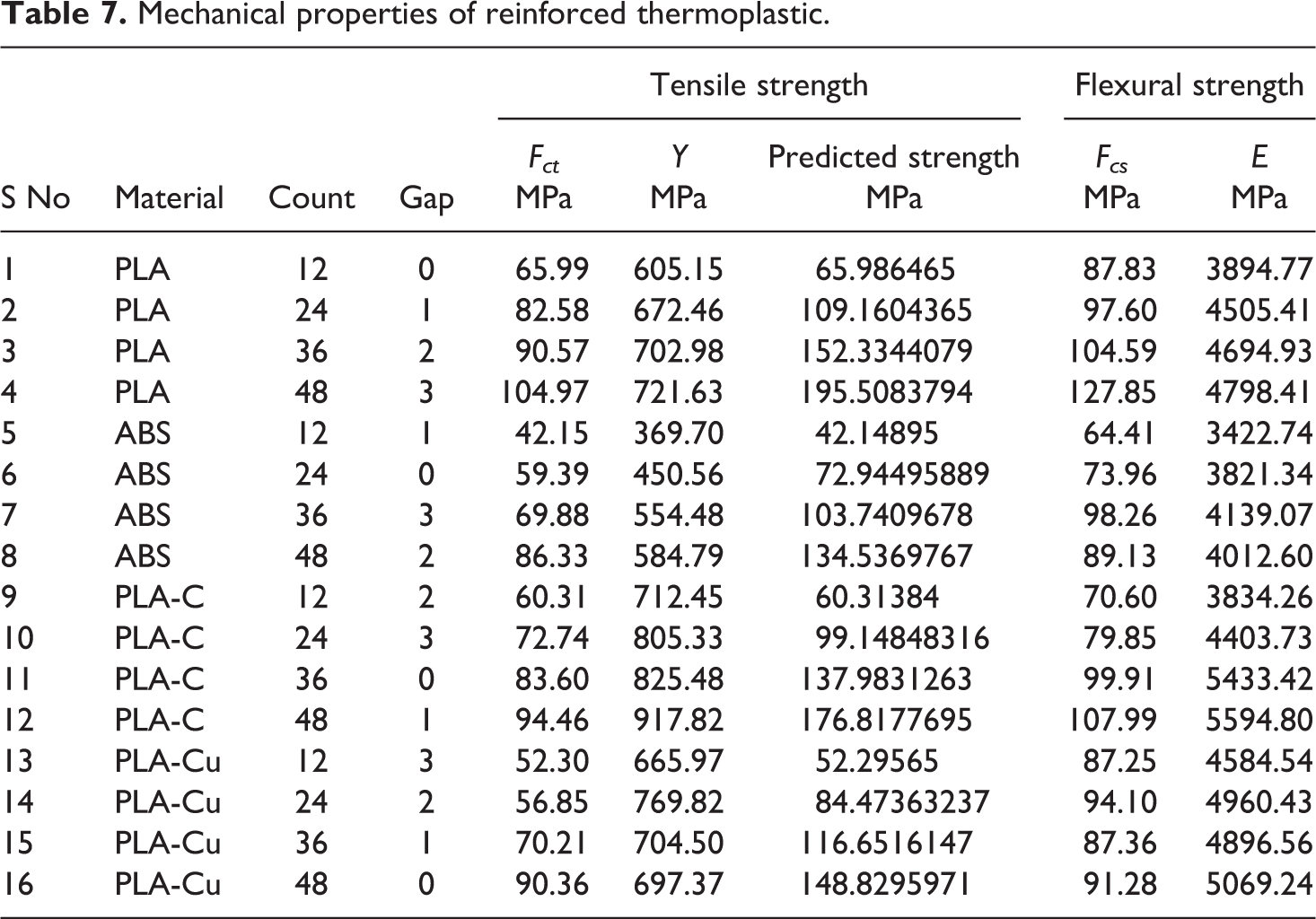
Figure 11 represents graphical comparison of the material wise improvement in tensile strength achieved, while Figure 12 represents graphical comparison of the material wise improvement in flexural strength achieved. Error bars are also displayed for each setting showing the variation in data observed. For larger variations, more than 02 samples were fabricated and tested. It must be noted that the comparison has been made with the baseline strength values of thermoplastics that have been presented in Table 6. Linear increment in tensile strength observed shows the minimal effect of inducing layer gap, while a more significant effect is observed in case of flexural strength. However, primary effect is that of layers of threads added to the thermoplastic matrix. Also, strength increase is observed at the lowest Vf which is also a proof that lowest selected Vf is greater than Vmin.
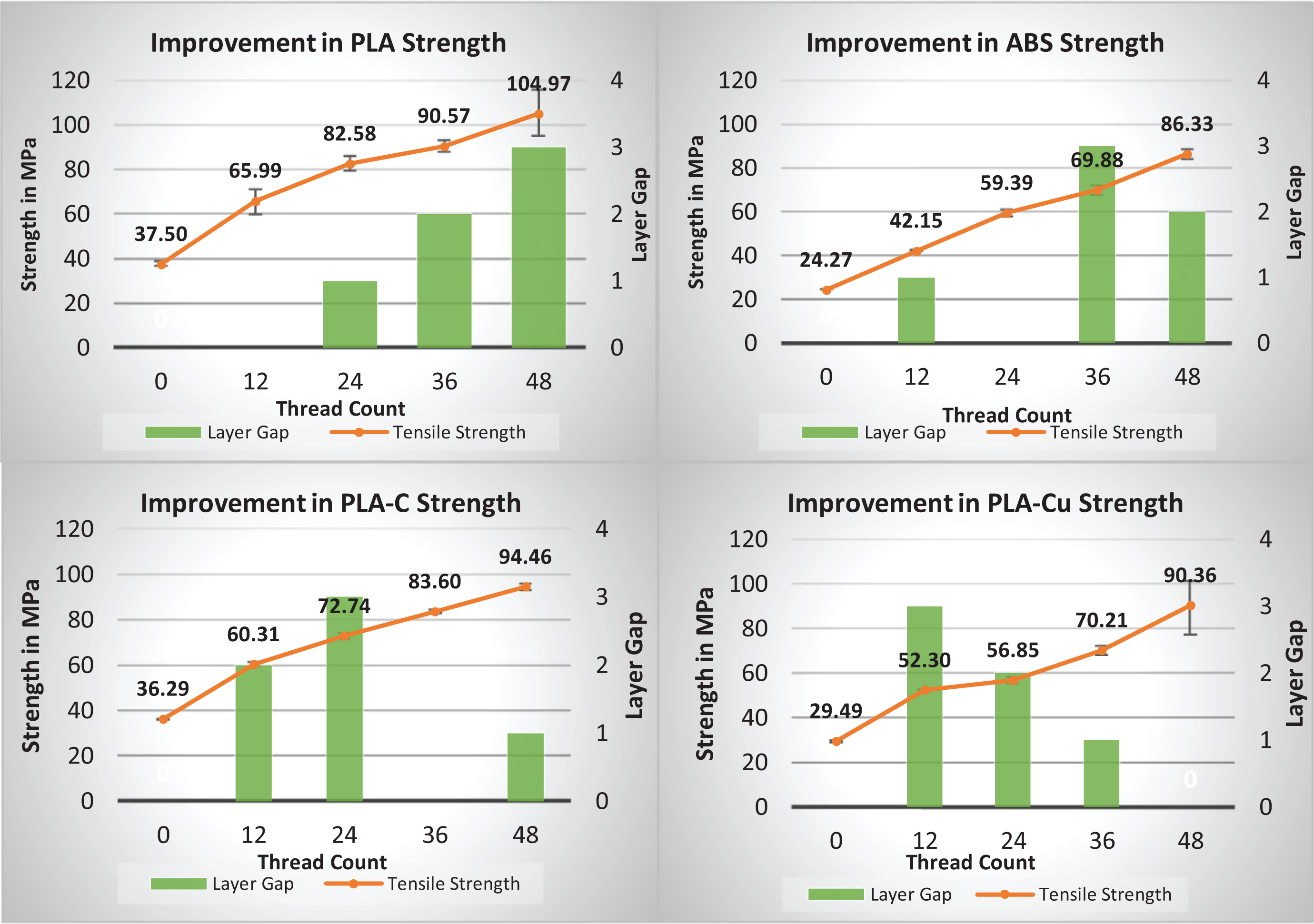
Comparison of tensile strength.
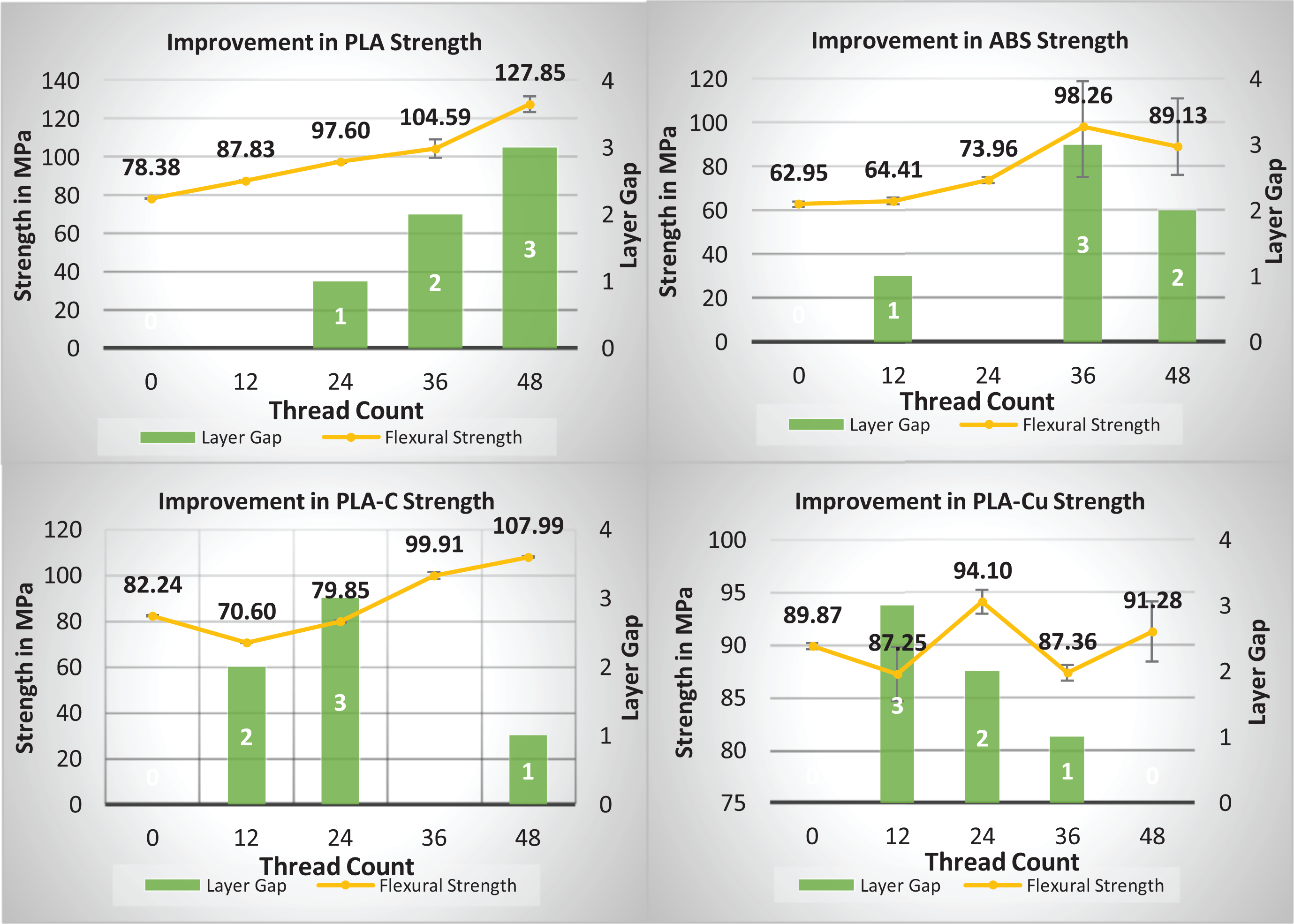
Comparison of flexural strength.
Fracture surface analysis
Figure 13 shows the fracture surface of thermoplastic samples. The surface has roughness with smooth patches at the edges suggesting crack propagation for a small region and instantaneous fracture for the remaining surface common in brittle materials. Therefore, as indicated by literature review as well, it is clear that thermoplastics used in this research exhibit brittle behavior.10,15,35 Similarly, the fractured surface of reinforced samples showed evidence of brittle failure which was also supported by the stress–strain curves obtained for each specimen. It was found that fiber pull out occurred in all the fractures with thermoplastic failure occurring prior to the failure of threads. This failure pattern was common for all tensile and flexural samples.
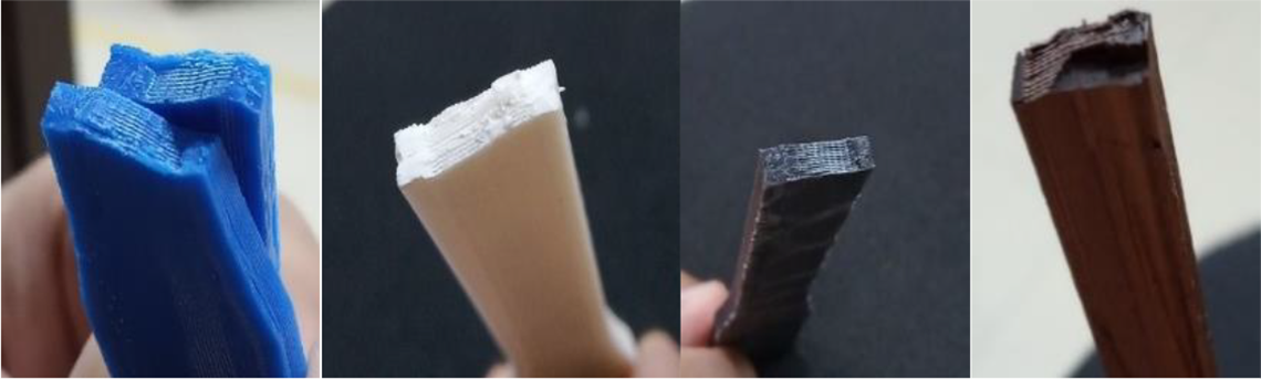
Fracture surface for thermoplastic specimen.
Tensile testing of samples also yielded similar results of fiber pull out and void formation. Figure 14 shows the fiber pull out phenomena for tensile samples, here also matrix failure occurred first. However, thread was not strong enough to elongate subsequent to failure of matrix and broke almost immediately after the failure of matrix, which was also evident from stress–strain curves for tensile samples. Similarly, cross-sectional view of tensile sample shows void formations similar in nature to flexural samples. These voids are smaller than the voids formed in case of flexural samples due to the type of load applied. Figure 15 contains side and cross-sectional view of broken flexural samples, showing fiber pull out and weak interface between plastic and fiber. Also, there are void formation near fiber which is another indicator of weak fiber to thermoplastic bond. Any void/discontinuity is a precursor for failure in an object under load. “Fiber pull-out” phenomena is common in composites that exhibit weak bond between fiber and matrix.19,21,23,26
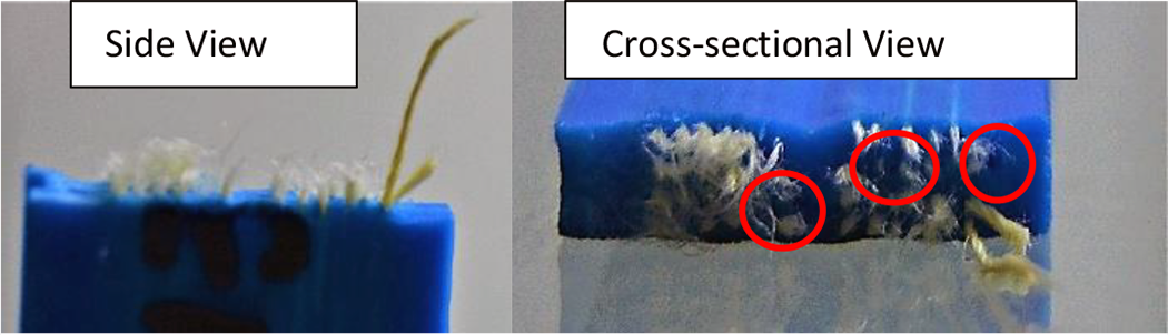
Broken tensile samples.
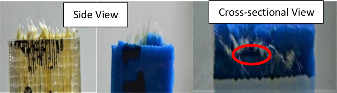
Broken flexural samples.
Statistical analysis using Minitab
Minitab, a powerful statistical analysis tool, was utilized to further verify validity of the results achieved for this novel CFRTPCs fabrication technique. Data presented in Table 7 were the input for this analysis. The results obtained are presented in Table 8 while the main effect plots are shown in Figure 16. “SNRA” represents S/N ratio, “STDE” represents standard deviation of the replicates, and “MEAN” is the mean value of the replicates of a trial run. For the OA used, S. No. 4 of the table represents the highest achieved S/N ratio.
Calculations using Minitab.
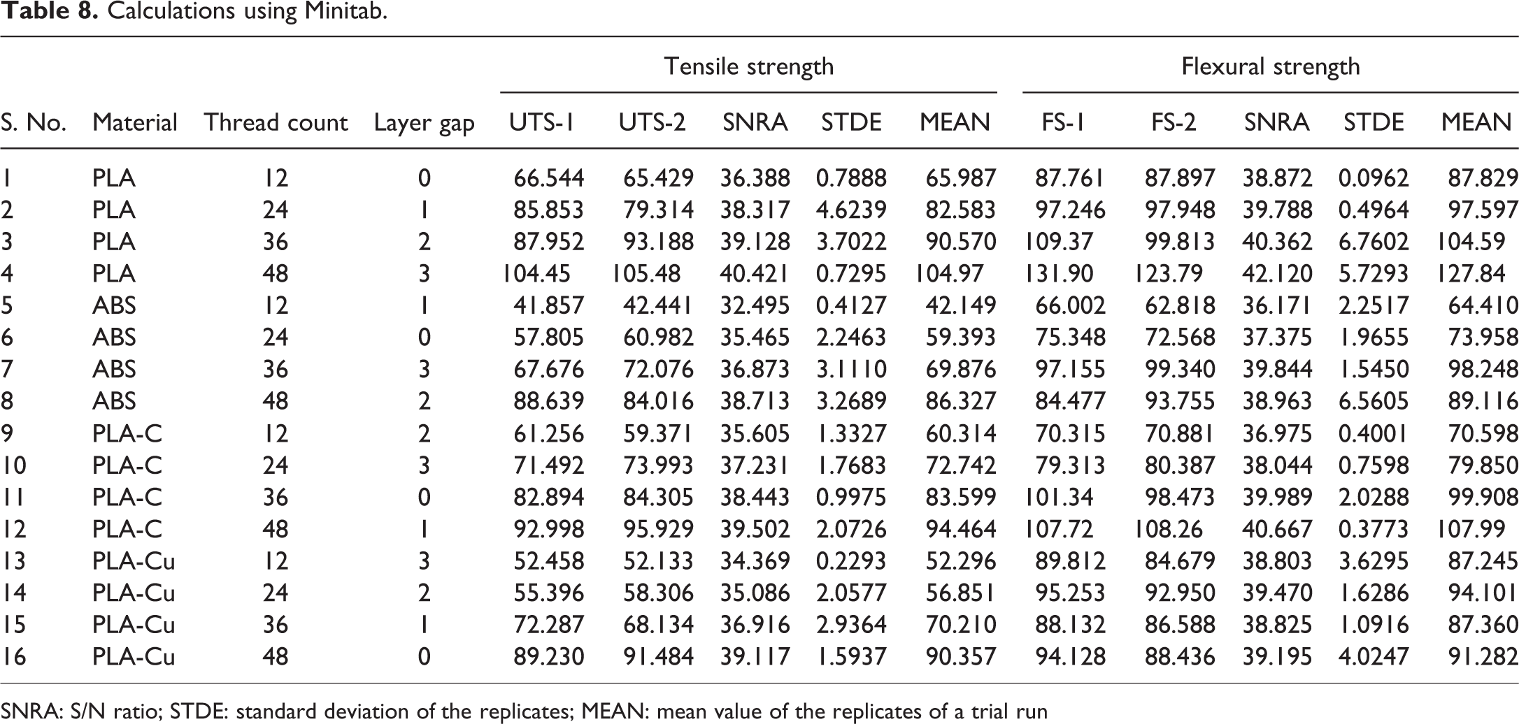
SNRA: S/N ratio; STDE: standard deviation of the replicates; MEAN: mean value of the replicates of a trial run
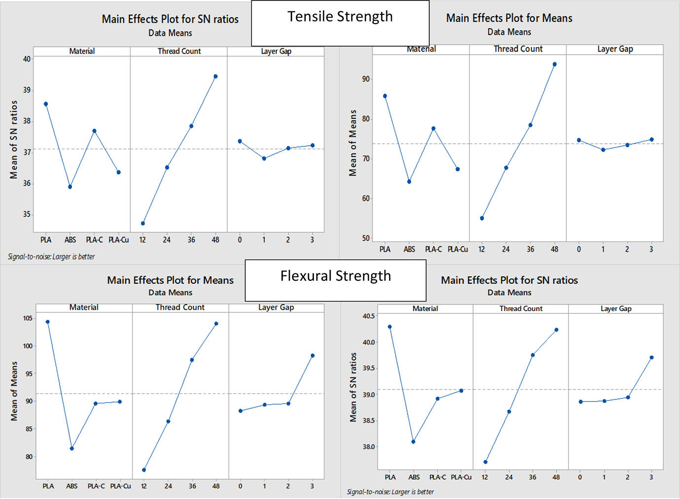
Main effect plots for tensile and flexural strength.
It is clear from main effect plots for tensile strength that layer gap, induced to improve bonding between fiber and matrix, has little to no effect on the strength of the part while thread count has a directly proportional effect on maximizing strength. However, results obtained for flexural strength show that in this case, addition of layer gap has a positive impact on strength. This is also evident from the main effect graphs shown in Figure 16. Introduction of thermoplastic layers between layers of fiber inhibits the formation of discontinuities. Hence, layer gap has a stronger effect on flexural strength than on tensile strength.
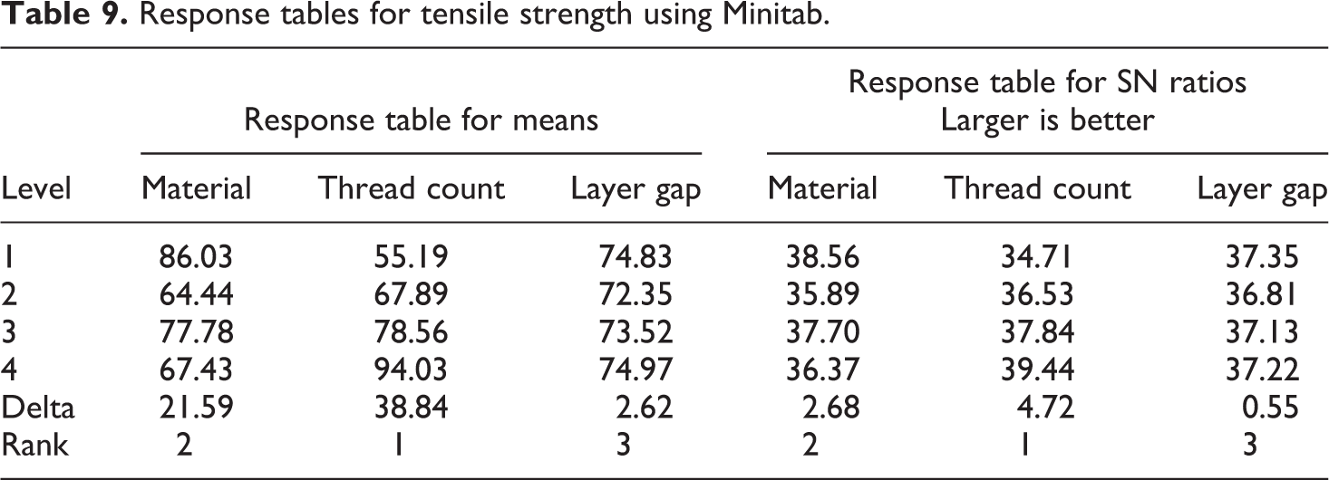
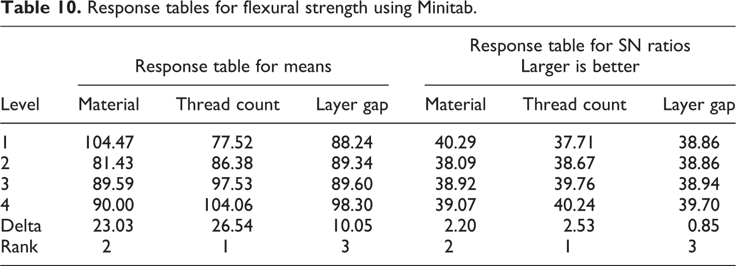
Response table summary for tensile strength is presented in Table 9; it shows that out of the variables considered for this study, layer gap has the least effect. Here it must also be noted that these tables show factor levels in coded units and the ranking of the factors is interpreted as the impact of each factor on the desired outcome. This ranking is based on the difference generated in S/N ratio and mean for each level of a factor. Thus, factor with largest delta has the highest impact on the outcome and is ranked first. Similar data obtained for flexural strength are presented in Table 10, also showing that layer gap has least impact out of all the considered variables.
Response tables for tensile strength using Minitab.
Response tables for flexural strength using Minitab.
Subsequently, analysis of variance on the estimated S/N ratios has also been carried out using Minitab and the results are summarized in Table 11 at α = 0.1 (confidence interval of 90%). This table also validates the finding that the layer gap has a very small impact. The p value in this table shows the relative importance of each factor and larger value here indicates least significance. As CI of 90% is selected, layer gap is insignificant for both mechanical properties. However, here also it is seen that layer gap is more significant in case of flexural strength as already postulated above.
ANOVA for SN ratios of mechanical properties.
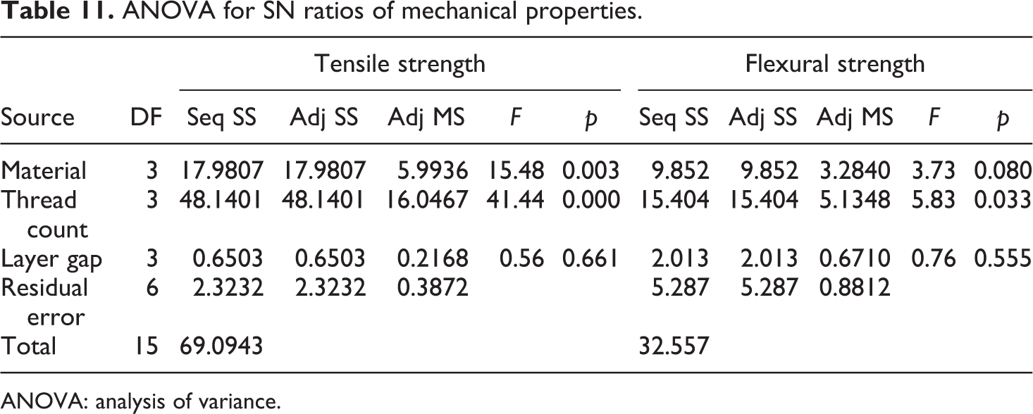
ANOVA: analysis of variance.
Optimization and confirmatory experiments
Regression equations for both flexural and tensile strength in the explored bracket were also determined using Minitab to provide quantitative figures for each parameter under discussion. This also corroborated that material and thread count, achieved through the novel fabrication technique, has a primary impact on the strength of a part. Layer gap had a negligibly small, albeit positive impact on tensile strength while significantly large impact was observed on flexural strength at highest gap selected for this study.
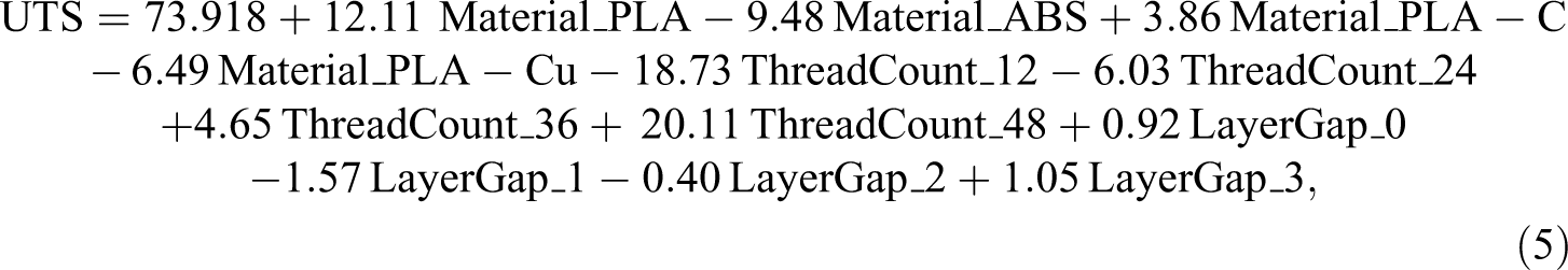
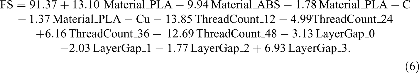
It can also be seen from these equations that PLA will have the largest impact in maximizing out outcome variables. Therefore, PLA, 48 thread count and 03 layer gap, yields the maximum tensile and flexural strength. As results for this combination of factors were already determined, there was no need of further experimentation.
Conclusion
To further expand upon the already conducted research,5,16,19,21,22 a novel technique for fabrication of CFRTPCs using FDM has been suggested here. This technique utilizes dual extrusion FDM system with modification of one-nozzle assembly to print fiber–matrix combination while other printed pure thermoplastic. Following are the important findings: Developed technique was able to better control volume fraction by printing fiber layers as and when desired in the part. Additionally, the fiber can also be printed in multiple directions independent of the thermoplastic shell, thus part strength can be increased manifold. It also provides protection to high strength fiber by printing a shell of thermoplastic and provides the flexibility of laying out fiber at multiple separate locations in the part. Superior surface finish with drastically high strength has also been achieved by using the developed technique. This novel technique was then validated using Taguchi DOE, followed by tensile and flexural testing. Thread count, layer gap, and materials were the factors considered for this investigation at 04 levels each. Promising results with tensile strength improvement of up to three times (105 MPa against baseline value of 37 MPa) than that of the thermoplastic and flexural strength improvement of up to almost two times (128 MPa against baseline value of 78 MPa) at a very low volume fraction were achieved. As the print speed of thermoplastic layer was larger, they inhibit void formation. Therefore, layer gap was studied in this research work. Significant improvement in flexural strength was observed while, in case of tensile strength, this phenomenon did not reveal any appreciable impact. Fracture analysis showed fiber pull out phenomena due to weaker bond between fiber and thermoplastic, while the brittle nature of thermoplastic was also evident from fracture mode.
Future recommendations
In this research work, unidirectional CFRTPCs have been investigated while the process is capable of producing multidirectional CFRTPCs, as shown in Figure 5, which would further enhance mechanical properties. This may also be further investigated. Theoretically, the process is applicable for all fibers as long as they can bear the temperature at the nozzle assembly. However, testing may be carried out with other fiber categories (natural, synthetic, and metal) to determine special requirements for adopting this procedure. Furthermore, this technique has the potential of improving acceptability of FDM for part fabrication in industry.
Tested samples show that there is a weak interface between plastic and fiber that has contributed to failure. In composites, the mechanical properties are primarily dependent upon the strength of bond between fiber and matrix.36–38 The mechanical strength of the samples can further be improved by treating fiber or thermoplastic with chemicals that improve miscibility of thermoplastic with fiber. Similarly, gluing agents such as epoxy can also be added to fiber layers in the samples during the process which may also enhance mechanical properties.