
Abstract
The emergence of additive manufacturing has enabled scientists to efficiently construct complex geometries, facilitating the development of novel, high-impact energy-absorbing structures suitable for a wide range of industrial applications. The present study conducted flexural and impact test to quantitatively assess the energy absorption capabilities of polymer composites fabricated through fused filament fabrication. Specifically, the polymer composites investigated were multi-walled carbon nanotubes reinforced poly-lactic acid, carbon fibre reinforced poly-ethylene terephthalate glycol, and carbon fibre reinforced poly-lactic acid. The investigation also examined the influence of different infill patterns and nozzle hole diameters on the polymer composites. The investigation depicts that by altering the process parameters, the flexural strength is improved from 21.079 MPa to 70.653 MPa by 235.18%. The experimental study of impact specimens utilising the Izod impact test demonstrates that the rectilinear infill pattern and a nozzle hole diameter of 0.6 mm result in the highest energy absorption of 37.76 kJ/m2 for carbon fibre reinforced poly-lactic acid. The study revealed that the energy absorption of the specimens was significantly influenced by both the independent and interaction effects of process variables. The application of the fused filament fabrication demonstrates an improved energy absorption, making it suitable for manufacturing of vehicle and aircraft components.
Keywords
Introduction
The adaptability, design flexibility, low volume production, waste reduction, and other benefits of 3-D Printing also known as additive manufacturing have led to its widespread use during the past decade.1,2 Producing high-quality products with complicated geometries, optimised topologies, increased interior structures, and multi-material combinations is all possible with this technology. In particular, it may be indicating an increasing interest in developing functioning parts that are subjected to complicated mechanical and thermal loading conditions while they are in service. Therefore, in order to guarantee the continued success of things that have been additively manufactured, it is important to go deep into the topic for the association between the parameters and the mechanical performance of the product. Stereolithography (SLA), fused filament fabrication (FFF), laser assisted bioprinting (LAB), selective laser sintering (SLS), and robotic assisted deposition (RAD) are additive manufacturing technologies. Each technology has advantages and disadvantages in terms of processing capacity, cost, print quality, and performance. Most of these methods use a slice model of a solid product where each layer is deposited on the previous one. FFF builds solid objects from layers following a specified design.3,4 The filament is heated and extruded through a tiny nozzle hole to deposit layers of fused material, Figure 1. To ensure printing quality, filament must tolerate mechanical and thermal stress from feeding and melting.5,6 Schematic representation of the FFF process.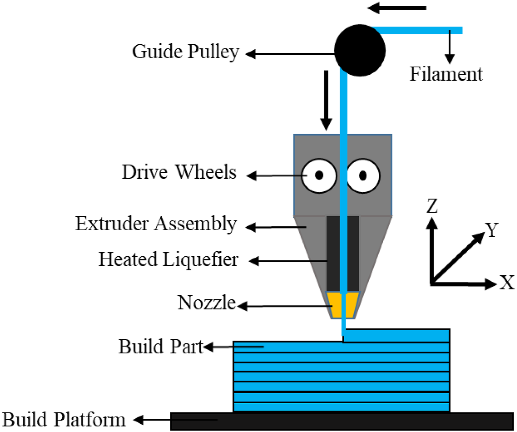
The mechanical performance of fabricated products depends on the following factors: fabricating material, liquefier temperature, fabrication speed, layer positioning, layer height, layer to layer adhesion, raster width, infill percentage, mesostructure, and air void.7–9 Experimental data, established testing techniques, and theoretical models are needed to understand the parameter-property relationship. Poly-lactic acid (PLA),10–14 acrylonitrile butadiene styrene (ABS),12,15 high density poly-ethylene (HDPE), 16 polycarbonate (PC),11,17 thermoplastic poly-urethane (TPU),18,19 poly-ether ether ketone (PEEK), 20 poly-hydroxy-alkanoate (PHA), 10 polyphenylene sulphide (PPS) 21 and their blends and composites are popular fabrication materials for FFF due to their functional characteristics. One of the most significant developments is the reinforcement of the polymer matrix. 22 Reinforcing poly-ethylene terephthalate glycol (PETG) and PLA filament with materials like copper, 23 bamboo, 24 wood fibre, 25 oil palm fibre, 26 glass fibre, 27 single walled carbon nanotubes, graphene,13,28 multi walled carbon nanotubes (MWCNTs), 16 and carbon fibre (CF)29–31 improves their mechanical, electrical, and thermal characteristics.30,32–34 The physical, electrical and mechanical properties of goods made using FFF fabrication methods benefit substantially from the use of carbonaceous reinforced polymer composites.35,36 Also, Polymer metal composites can replace metal components due to their lightweight, corrosion resistance, and strength. Examples include carbon fiber-reinforced polymers in aerospace (e.g., Boeing 787) and polymer-coated metal implants (e.g., orthopaedic devices) for improved performance and durability.
Impact testing is an excellent way to begin investigating how the mesostructure affects the fracture behaviour of fabricating materials.37,38 While the Izod impact test have been well created for testing various materials, and preferable for assessing various polymer and their composites. Impact test is great for learning about a material's fundamental fracture mechanics since they quantify the measure of energy absorbed by the material just prior to failure under high-strain-rate conditions. The fracture mechanism is investigated in this work, which measures the total energy needed to commence a fracture in the specimen via impact. Clearly, additional research is needed to properly comprehend the crack behaviour in fabricated specimens, but an impact test is a fast and simple technique to collect preliminary findings that may be used to make preliminary comparisons between materials and orientations. Because of this, a sizable dataset may be generated at low cost, that can be utilised to influence product design outcomes and potential studies into the fracture behaviour for the different materials.
Fused filament fabrication structural durability depends on the infill pattern (IFP) and infill density. The filament deposition direction and rate determine the IFP of FFF-fabricated products. Wiggle, rectilinear, honeycomb, octet, cross, and triangular are some popular IFPs. 39 The IFPs alter heat transmission between bonded layers while affecting strength, material use, and production time. Except for small objects, the infill occupies greater space than the external shell and dominates. On the other hand, extrusion and layer deposition are governed by nozzle hole diameter (NHD) in the FFF process. 40 How layers are built up and how quickly filaments are deposited have a direct impact on the mechanical properties of the structures made with FFF. Effective molecular fusion at bonded interlayers contributes to greater mechanical strength in the final manufactured components. 41 The endurance of FFF-fabricated parts under impact load is one of the primary challenges because these parts are often made for functional purposes. There have been a limited number of studies done to investigate how impact behaviour is affected by the variables that are involved in the FFF process.
Mechanical performance of filaments created from ABS, PLA, and PLA/PHA were studied by Oviedo et al. 10 In order to limit the anisotropic functionality of additively manufactured specimens, a morphological study showed that a fused and dense IFP paired with thick double oriented rasters would be useful. 10 Patterson et al 11 examined the relationship between printing orientation and raster angle for the impact behaviour of several FFF materials. The impact resistance of brittle FFF materials is more coherent, but they are also weak. Stronger, but less predictable, impact characteristics can be found in materials that plastically bend greatly before cracking. 11 Atakok et al 42 used the Taguchi approach to analyse the results of varying the layer height, occupancy rate, and IFP of FFF constraints on the structural behaviour of additively manufactured PLA and recycled PLA test parts. According to Czyzewski et al, 43 the percentage of air gaps between the print channels was noticed to rise with NHDs, as determined by microscopic examination of the fractures in the samples. Values for impact strength is varied with the voids between the courses of the polymer material, indicating that these occurrences may affect the impact strength. 43 Wang et al 44 examined how layer height and bed temperature affect PLA's impact strength. Fractography of printed PLA indicated that 0.2 mm layer height and 160°C plate temperature reduced voids due to diffusion. Tezel et al 17 reported that all materials and layer heights combinations had the lowest impact strength while upright orientation. According to Mishra et al, 45 impact strength is strictly dependent on the mesostructure, which balances stress intensity and crack propagation. The concentric pattern's stress concentration increased the mesostructure’s produced stress, causing it to shatter with less energy than others. Mesostructure layer delamination interrupts impact crack propagation. The fracture region's crack propagation stoppage gradually boosts the structure's energy-absorbing capabilities.
The input parameters of the FFF were optimised using several experimental designs, including ANOVA, full factorial design, fuzzy logic, the bacterium forging method, response surface methodology (RSM),8,46 and the Taguchi approach.13,25,47,48 Due to its robustness, tolerance, and dimension control, Taguchi's design of experiments methodology was commonly used to optimise FFF parameters. Taguchi experimental design enhances quality and provides strong design solutions. 49 Compared to other methods, this one has the added benefit of optimising multiple aspects at once and getting more quantitative data out of fewer trials in the experiment. Experimental designs can take several shapes, but RSM is a versatile approach for assessing the impacts of diverse factors and forecasting the most crucial input parameters.50,51
Very few researchers work on the energy absorption characteristics of polymer composites. The energy absorption capabilities of polymer composites are an area that needs more investigation and improvement. This is especially true considering the widespread use of these materials in the aerospace and automotive sectors. The concurrent investigation of IFP and NHD on polymer composites within reviewed papers may indeed represent an unexplored research area. In order to increase safety and performance in aerospace and automotive sectors, it is necessary to do a focused study on these qualities. By improving and tailoring these features, it will produce innovative composite materials with better crashworthiness, impact resistance, and structural integrity.
In this study, the effect of polymer composites and process constraints on the mechanical behaviour namely flexural and impact behaviour of FFF-fabricated specimens is investigated. In view of this, an assessment of the mechanical behaviour of carbon fibre reinforced poly-lactic acid (CF-PLA), carbon fibre reinforced poly-ethylene terephthalate glycol (CF-PETG), and multi walled carbon nano tubes reinforced poly-lactic acid (MWCNTs-PLA) is carried out by altering selected parameters such as IFP and NHD, and then high-resolution microscopy is carried out for the fracture surfaces to comprehend more about the failure mechanisms. The results of the impact testing are analysed using Taguchi's technique and RSM to investigate how the mechanical behaviour depends on the selected process factors.
Material and method
The selected reinforcement particles and the polymers purchased from Augment 3Di, India. CF: Diameter 4–7 µm, length 190–210 µm, and >98% purity. MWCNTs: Diameter 8–15 nm, length 1–3 µm, and purity of >90%. PLA: Melt Flow Index 14 g/10 min, melting temperature 150°C, and purity of >95%. PETG: Melt Flow Index 8 g/10 min, melting temperature 135°C, and purity of >95%.
Mechanical agitation was used to create polymer composite materials of selected reinforcement particles and the polymers (purchased from Augment 3Di, India) with mass fractions of 20%.
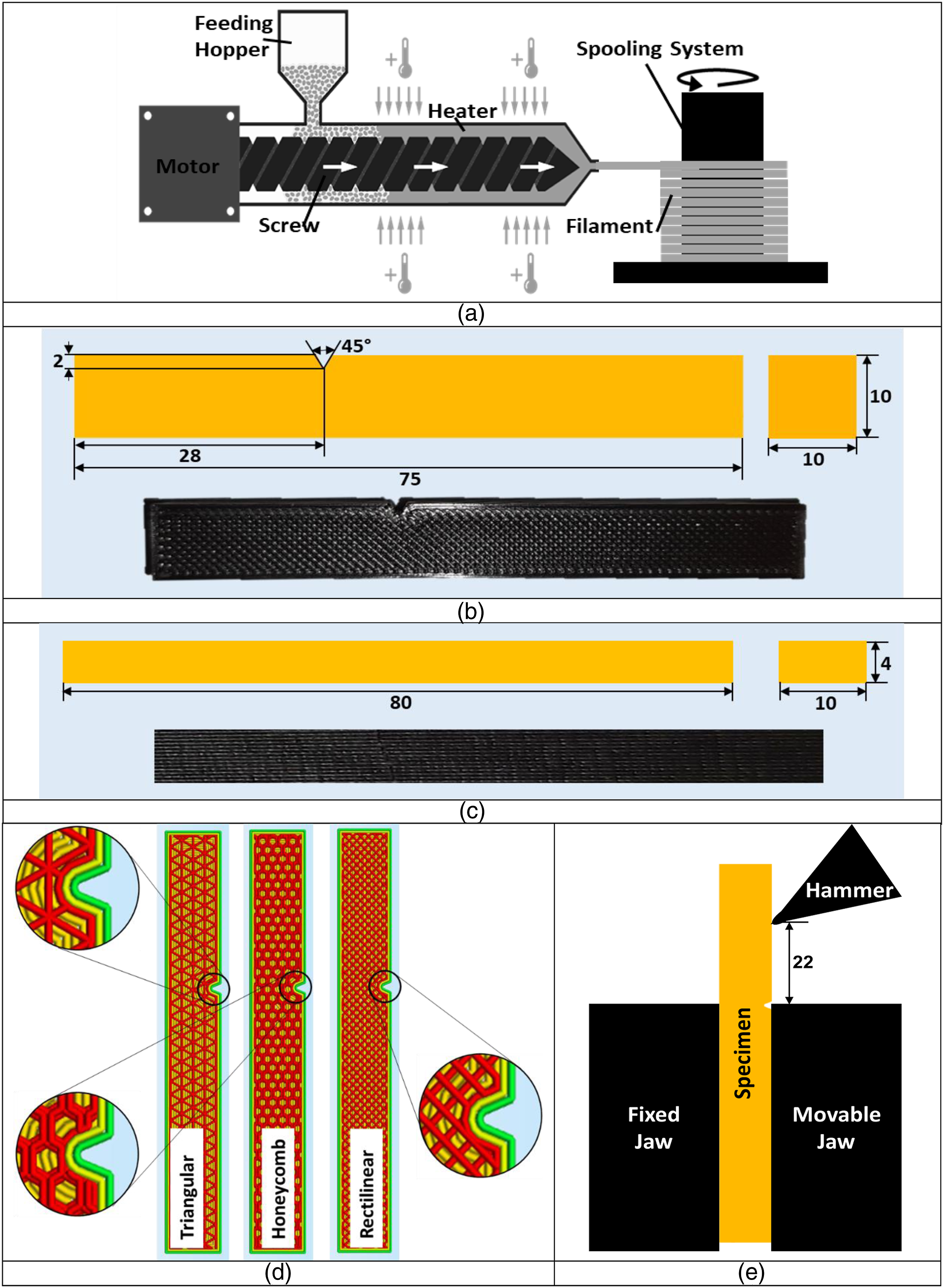
A hot air oven set at 50°C to eliminate excess moisture from the polymer pellets. Using a sealed environment and magnetic stirring for 12 hours, the polymer pellets were dissolved in the right amount of chloroform solvent according to predefined proportions. After the reinforcement particles were dissolved entirely, they were added to the mixture while it was still being agitated for 5 hours. This was the procedure for combining the solutions. The resulting cake batter was dried out in a continuous temperature drying oven at 80°C for 15 minutes in a glass drier. The cake batter was then frozen and sliced into small pellets for melt mixing. The blended material was sheared and extruded at a temperature range of 190°C–220°C with a screw speed of 70 revolutions per minute using a filament fabricating machine, Figure 2(a). After the melt was cooled and strained into a wire, three different polymer composite filament with 1.75 mm diameter was formed: 1. CF-PLA: PLA reinforced with 20% CF by weight and has the density of 1307 kg/m3 and the melting temperature in the range of 200°C–220°C. 2. CF-PETG: PETG reinforced with 20% CF by weight and has the density of 1345 kg/m3 and the melting temperature in the range of 195°C–230°C. 3. MWCNTs-PLA: PLA reinforced with 20% MWCNTs by weight and has the density of 1438 kg/m3 and the melting temperature in the range of 190°C–220°C. (a) Schematic view of filament fabricating machine (b) ASTM D256 specimen (c) ASTM D790 specimen (d) Selected IFPs (e) Schematic representation of Izod impact test.
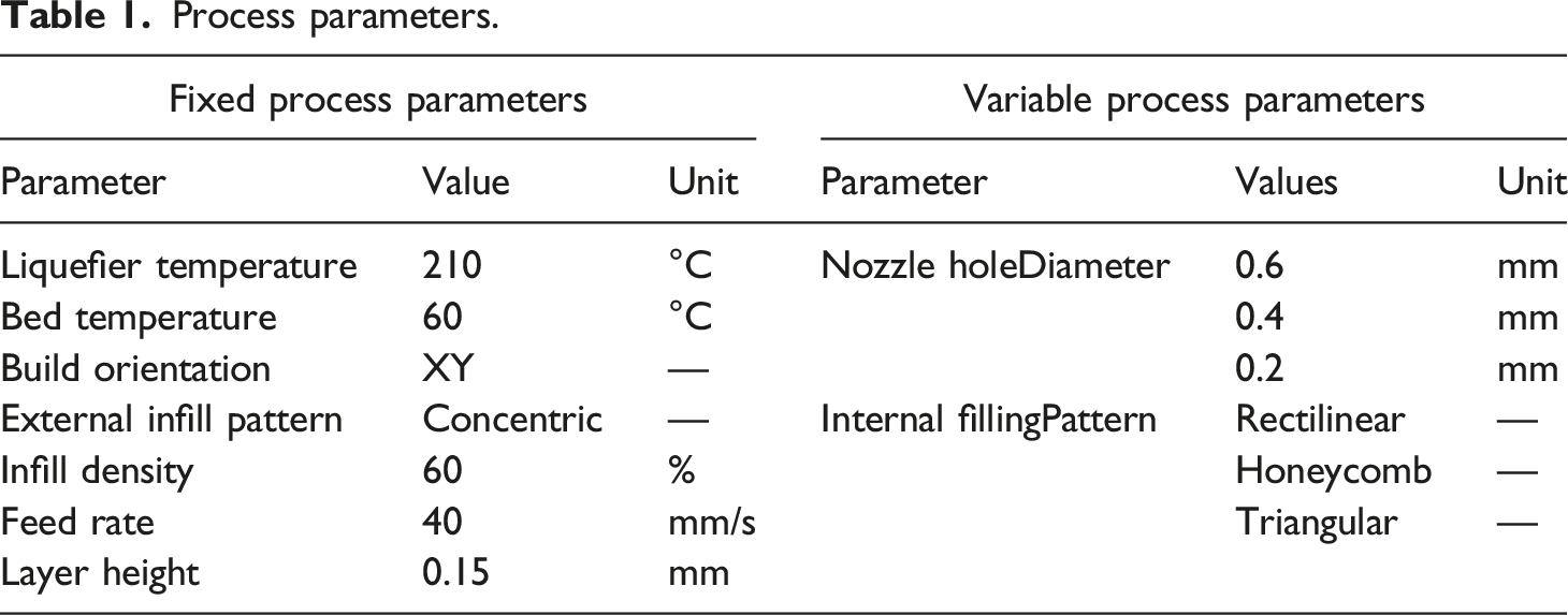
Process parameters.
Testing data for different polymer composites.
In this analysis, 27 specimens (set of 5) were created using three filaments of diameter 1.75 mm with fixed and variable process parameters, Table 1. Figure 2(d) depicts the three selected IFPs (triangular, honeycomb, and rectilinear) that were considered for this study. For the impact test specimen, the infill density employed is 60%. The fabricated specimens already have the notch built into them since it was part of the original specimen design, Figure 2(d).
The impact testing of the fabricated specimens was conducted using an Izod impact testing machine. Its pendulum measures 0.9949 m in length and 16.6 kg in weight, with a striking velocity of 3.2 m/s. Figure 2(e) depicts a diagrammatic representation of the impact test.
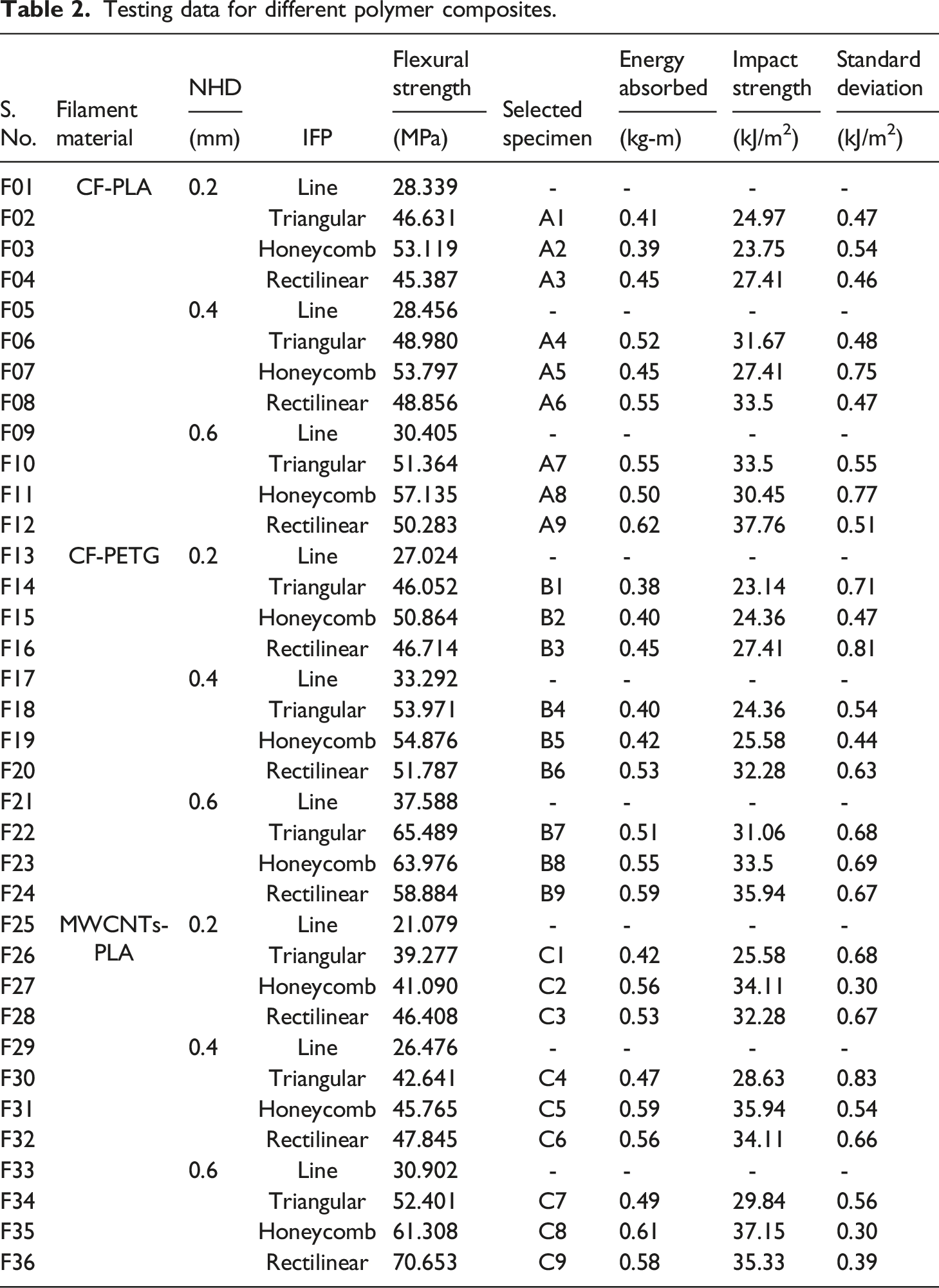
Table 2 displays the results of impact testing performed on CF-PLA, CF-PETG, and MWCNTs-PLA specimens. The effects of altering the parameters of the process and the materials utilized in the fabrication are analysed and compared. A filament material's fracture morphology is analysed and compared for better knowledge of failure mechanisms. To learn more about how changing process factors affect mechanical behaviour, the impact test data is analysed using ANOVA with the Taguchi method and RSM.
Results and discussion
Number of specimens used for each process parameter combination, including IFP (line, triangular, honeycomb, and rectilinear) and NHD (0.2 mm, 0.4 mm, and 0.6 mm) with CF-PLA, CF-PETG, and MWCNTs-PLA as the fabricating material, is illustrated in Table 2. For flexural behaviour of several specimens, the variation of stress against strain is depicted graphically in Figure 3. Stress strain graph for flexural behaviour at different IFPs (a) Line, (b) Triangular, (c) Honeycomb, (d) Rectilinear.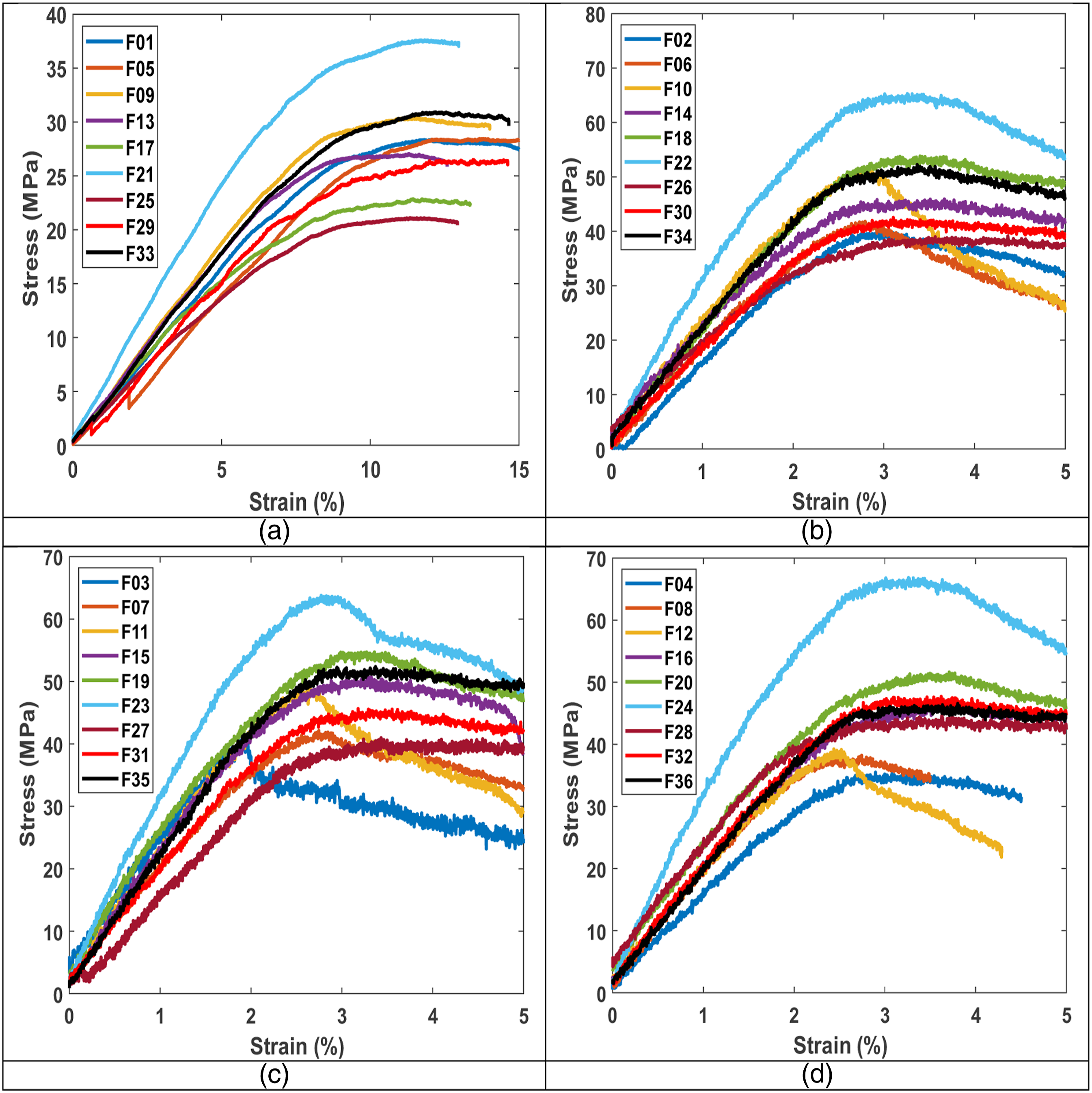
The minimum flexural strength obtained is 21.079 MPa at NHD 0.2 mm and line IFP for MWCNTs-PLA and the maximum flexural strength obtained is 70.653 MPa at NHD 0.6 mm and rectilinear IFP for MWCNTs-PLA, hence flexural strength is enhanced by 235.18% by varying the selected process parameters.
The examination of impact behaviour for a specific NHD involves the selection of the top three IFPs, which are determined based on their flexural strength. Further, this section covers the comparative experimental, fractographic, and statistical analysis of the impact test specimen that was caused by a change in the NHD and selected top three IFPs.
Experimental analysis
The discussion for this part will focus on the effect that NHD and IFP have on the impact strength of the fabricated specimen. Figure 4 illustrates the impact strength variation for different impact specimen. Impact strength variation for different specimens.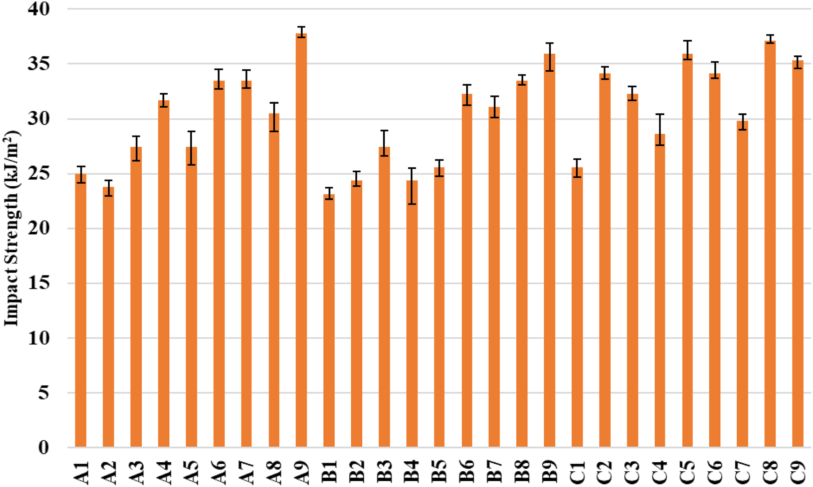
Effect of nozzle hole diameter
Three different values of NHD viz 0.2 mm, 0.4 mm, and 0.6 mm are utilized in this experiment. NHD is the factor that decides both the possible layer height and, by extension, the fabrication speed in an indirect manner. In the following section, a comparison of the impact strength is carried out at various NHDs for a specific IFP.
Carbon fibre reinforced poly-lactic acid
The impact strength attained for specimen A3 is 27.41 kJ/m2 at NHD 0.2 mm for rectilinear IFP, and this increases by 22.22% and 37.76%, when the NHD is increased to 0.4 mm (33.50 kJ/m2, A6) and 0.6 mm (37.76 kJ/m2, A9), respectively. The impact strength is increased by 34.16% and 26.83% on altering the NHD from 0.2 mm (A1, 24.97 kJ/m2) to 0.6 mm (A7, 33.50 kJ/m2) and 0.4 mm (A4, 31.67 kJ/m2), respectively while IFP is triangular, Figure 4. By expanding the bonding area between neighbouring rasters, the NHD increment improves the impact behaviour while all other parameters are held fixed.
For CF-PLA, larger NHD allowed the deposition of a greater volume of filament material per layer. This increased material flow rate can facilitate better alignment and distribution of the CFs within the printed part. Improved fibre alignment enhanced the load-bearing capability and impact resistance of the CF-PLA, resulting in higher impact strength.
Carbon fibre reinforced poly-ethylene terephthalate glycol
For CF-PETG specimens with honeycomb IFP, the impact strength is enhanced by 37.52% and 5.01% on adjusting the NHD from 0.2 mm (B2, 24.36 kJ/m2) to 0.6 mm (B8, 33.50 kJ/m2) and 0.4 mm (B5, 25.58 kJ/m2), respectively. The impact strength observed for specimen B3 is 27.41 kJ/m2 at NHD 0.2 mm for rectilinear IFP, and this improves by 22.22% and 37.76%, when the NHD is modified to 0.4 mm (32.28 kJ/m2, B6) and 0.6 mm (35.94 kJ/m2, B9), respectively, Figure 4. Due to their high degree of fusion and sparse distribution of voids, the CF-PETG specimens' impact strength is improved by an elevation in NHD.
Using a larger NHD can significantly reduce the print time compared to smaller NHD. Reduced print time can have a positive impact on the interlayer bonding of the CF-PETG, as there is less time for each layer to cool and solidify prior to the subsequent layer is deposited. Improved interlayer bonding contributes to increased impact strength.
Multi walled carbon nano tubes reinforced poly-lactic acid
The impact strength accomplished for specimen C2 is 34.11 kJ/m2 at NHD 0.2 mm and boosted by 5.36% and 8.91% for honeycomb IFP when raising the NHD to 0.4 mm (35.94 kJ/m2, C5) and 0.6 mm (37.15 kJ/m2, C8), respectively. Because internal angles in honeycomb structures are greater, that helps to disperse the impact force inside the body more evenly. For MWCNTs-PLA specimens with triangular IFP, the impact strength is enhanced by 16.65% and 11.92% on adjusting the NHD from 0.2 mm (C1, 25.58 kJ/m2) to 0.6 mm (C7, 29.84 kJ/m2) and 0.4 mm (C4, 28.63 kJ/m2), respectively, Figure 4. Since the impact strength of the MWCNTs-PLA specimens grows with the specific gravity of the produced specimens, increasing the NHD while keeping the other process variables constant raises resistance to the impact force.
With a larger nozzle diameter, the MWCNTs-PLA material can flow more easily and smoothly through the nozzle during the printing process. This improved material flow can minimize issues such as clogging and uneven extrusion, which could adversely affect the structural integrity and impact strength of the fabricated part.
Effect of infill pattern
The experiment employs three distinct IFPs, including triangular, honeycomb and rectilinear. IFP is the determining factor for the impact strength of the different specimens, which is compared for different IFPs for a given NHD in this section.
Carbon fibre reinforced poly-lactic acid
The impact strength accomplished for specimen A4 is 27.41 kJ/m2 for honeycomb IFP and boosted by 15.54% and 22.22% at NHD 0.2 mm on altering the IFP to triangular (31.67 kJ/m2, A5) and rectilinear (33.50 kJ/m2, A6), respectively, Figure 4. The CF-PLA specimens with the honeycomb IFP had the least impact strength of 23.75 kJ/m2 (A2) with NHD 0.2 mm. This can be linked to different ways of breaking inside the structure. In contrast to other designs, which are made up of transversely continuing lines, this one is made up of lines that zigzag across one another, creating linkages between them. These connections are notoriously weaker than the lines themselves and may lead to a breakdown.
It is also observed that CF-PLA specimens with rectilinear IFP exhibit better resistance to delamination. The continuous parallel lines in the IFP act as barriers, restricting crack propagation and minimizing the risk of interlayer separation. Delamination can be a critical mode of failure during impact testing, and the rectilinear IFP facilitates to mitigate this issue, thereby increasing the impact strength.
Carbon fibre reinforced poly-ethylene terephthalate glycol
With an NHD of 0.2 mm, the CF-PETG specimens with triangular IFP, B1 exhibited the lowest impact strength, at 23.14 kJ/m2. Because the triangular IFP produces a simpler structure without any internal redundancies, it has the lowest impact resistance. Additionally, because cracks would put considerably higher strain on the interior structure, it is more prone to failure. For CF-PETG specimens at NHD 0.6 mm, the impact strength is enhanced by 7.86% and 15.71% on modifying the IFP from triangular (B7, 31.06 kJ/m2) to honeycomb (B8, 33.50 kJ/m2) and rectilinear (B9, 35.94 kJ/m2), respectively, Figure 4.
Rectilinear IFP enhances interlayer bonding, increasing contact area for better adhesion. Its parallel lines distribute impact forces, elevating structural integrity by efficient load transfer. This pattern outperforms triangular and honeycomb IFPs, forming interconnected ribs for effective energy distribution, reducing localized failures, and boosting impact strength.
Multi walled carbon nano tubes reinforced poly-lactic acid
The impact strength for specimen C4 is observed to be 28.63 kJ/m2 for triangular IFP. Switching the IFP to rectilinear (34.11 kJ/m2, C6) and (35.94 kJ/m2, C5) increases the impact strength by 19.14% and 25.53% at NHD 0.2 mm, respectively, Figure 4. With an NHD of 0.6 mm, the MWCNTs-PLA specimens with honeycomb IFP, C8 exhibited the highest impact strength of 37.15 kJ/m2. Because internal angles in honeycomb structures are greater, that helps to disperse the impact force inside the body more evenly.
The honeycomb IFP enhances energy absorption in impact tests for MWCNTs-PLA. Its hexagonal cells deform under stress, dispersing impact energy and distributing forces, boosting impact strength. The geometric configuration grants structural stability, resisting deformation and reinforcing the part against impacts, surpassing triangular or rectilinear IFP in impact resistance.
Fracture analysis
In this section, the high-end microscopic images are examined for various mechanisms of failure, such as raster failure, weak bonding, voids, layer separation, delamination, and raster separation, for selected tested specimens. Understanding how well a fabricating material and process parameters prevents failure is important when analysing its impact behaviour. It is clear, as demonstrated by the fractography of the tested specimens, that different breaking fracture modes are discernible for the different IFP and NHD. During a standard Izod impact test, the load influence might be affected by the geometry of the IFP. Additionally, the NHD has a significant effect on bonding between adjacent rasters and layers. For comparative examination, the high-end microscopy is performed for the specimen with maximum impact strength at particular IFP.
Carbon fibre reinforced poly-lactic acid
The effects of IFP on the failure mechanism of the CF-PLA specimens are illustrated in Figure 5. The failure of specimen A7 is oblique to the notch due to individual raster failure with CF pullout, Figure 5(a), resulting in an impact strength of 33.50 kJ/m2, at NHD 0.6 mm and triangular IFP. Specimen A8 had minimum impact strength of 30.45 kJ/m2 at NHD 0.6 mm with honeycomb IFP due to its failure, which was predominantly caused by rupture of raster without pulling and necking, Figure 5(b). Failure in specimen A9 was induced parallel to the notch mostly by breaking of raster and CFs with sufficient pulling and necking, Figure 5(c), resulting in maximum impact strength of 37.76 kJ/m2 at NHD 0.6 mm and rectilinear IFP. This is due to structure-breaking methods. Unlike triangular and rectilinear IFPs, the honeycomb has zigzag lines in its structure. These connections are often weaker than the continuous lines. Fracture surface of the CF-PLA specimens at NHD 0.6 mm with different IFPs (a) triangular-A7, (b) honeycomb-A8, (c) rectilinear-A9.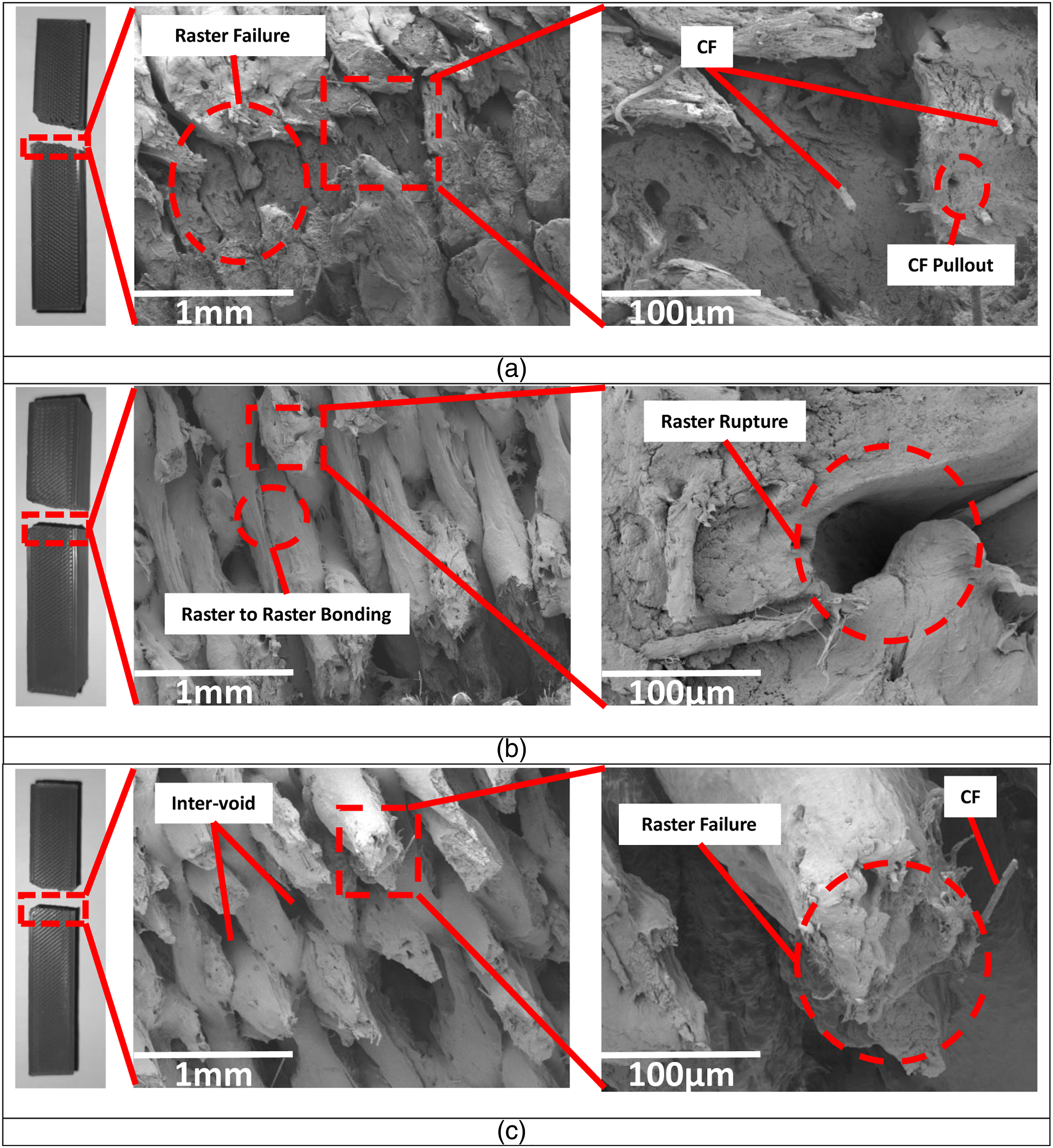
Weak raster bonding refers to insufficient adhesion between the layers, resulting in reduced strength and structural integrity. Adjusting these parameters including liquefier temperature, layer height, and IFP improve the bonding between the layers and enhance the impact strength of the CF-PLA specimens.
Carbon fibre reinforced poly-ethylene terephthalate glycol
Figure 6 illustrates the effects of IFP on the various failure modes that were seen in the CF-PETG specimens. CF-PETG specimens have failure oblique to the notch. The failure of specimen B8 is predominantly caused by intra-voids of the raster with CF pullout, Figure 6(b). Consequently, the specimen had an impact strength of 33.50 kJ/m2 at NHD 0.6 mm and honeycomb IFP. The failure in specimen B9 was caused mostly by the breaking of raster and CFs, Figure 6(c), which resulted in maximum impact strength of 37.76 kJ/m2 at NHD 0.6 mm and rectilinear IFP. Because of its failure, Specimen B7 had a minimum impact strength of 31.06 kJ/m2 at NHD 0.6 mm with triangular IFP. This was attributable to the fact that the voids between the neighbouring rasters and the CFs pullout weaken the raster, Figure 6(a), which was the primary reason for the failure. The triangular IFP has the lowest impact resistance because it generates a more straightforward structure that is devoid of any redundant elements on the inside, which would make it more susceptible to failure. Fracture surface of the CF-PETG specimens at NHD 0.6 mm with different IFPs (a) triangular-B7, (b) honeycomb-B8, (c) rectilinear-B9.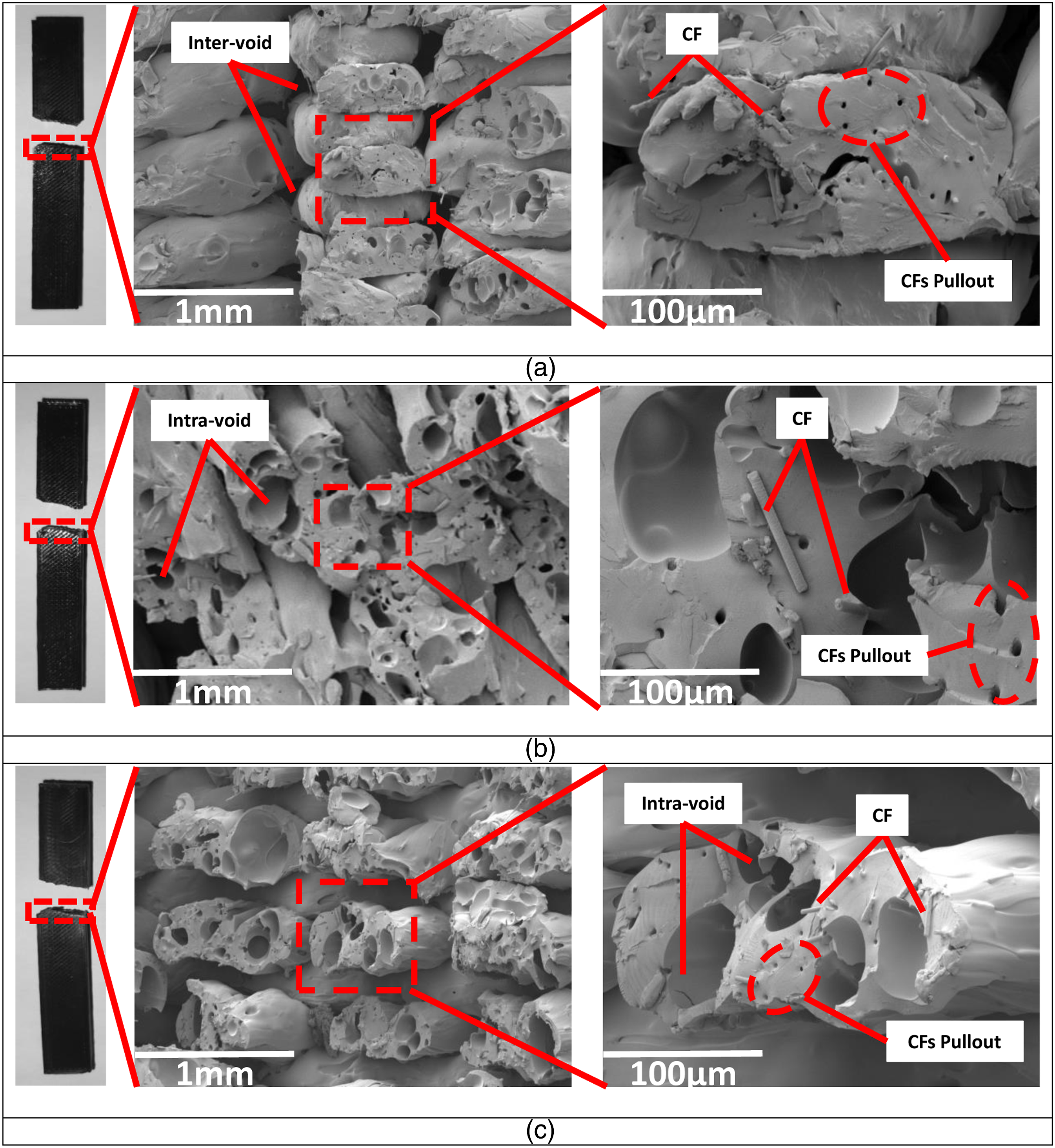
CFs of the CF-PETG filament provides increased strength and stiffness. The orientation and load sustaining capacity of the CFs within the printed part can greatly affect its impact behaviour. Optimizing the print parameters, such as IFP and NHD, provide the desired fibre alignment, minimize voids, and maximize impact resistance.
Multi walled carbon nano tubes reinforced poly-lactic acid
In Figure 7, the impacts of IFP on the various failure modes that were observed in the MWCNTs-PLA specimens are depicted with mostly failure oblique to the notch. Figure 7(a) illustrates that voids between the adjacent rasters are the primary cause of the brittle failure of specimen C7. As a direct result of this, the specimen had a minimum impact strength of 29.84 kJ/m2 when measured for triangular IFP and NHD 0.6 mm. Figure 7(c) reveals that the failure in specimen C9 was mostly caused by the breaking of raster depicting combination of ductile and brittle failure with impact strength of 35.33 kJ/m2 at NHD 0.6 mm and rectilinear IFP. Specimen C8 had a maximum impact strength of 37.15 kJ/m2 at NHD 0.6 mm with triangular IFP. This is because the specimen has more necking of the individual raster before failure in comparison to the other specimen, Figure 7(b). Honeycomb IFP, which have higher internal angles than other types of structures, help to distribute the force of an impact more equally throughout the specimen. Fracture surface of the MWCNTs-PLA specimens at NHD 0.6 mm with different IFPs (a) triangular-C7, (b) honeycomb-C8, (c) rectilinear-C9.
The addition of MWCNTs to PLA is intended to enhance impact behaviour. However, the concentration and dispersion of MWCNTs within the PLA matrix can significantly affect its impact behaviour. It is important to ensure that the MWCNTs are uniformly distributed and properly dispersed throughout the PLA filament to enhance the impact behaviour with improved toughness and reduced brittleness.
The fractography images shown in Figures 5–7 has different type of voids detected in the different specimens. Inter-voids occur recurringly as a result of raster spreading. Caused by the peculiarities of the flow of the fused material and the design of the nozzle. However, intra-voids develop within the raster. The existence of these voids affects the impact behaviour of the generated specimen and can be mitigated by modifying the proper process parameters.
Statistical analysis
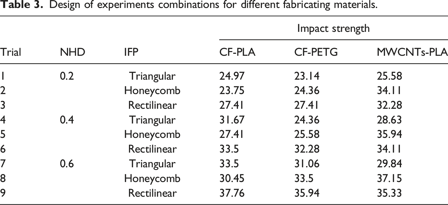
Design of experiments combinations for different fabricating materials.
ANOVA with Taguchi method
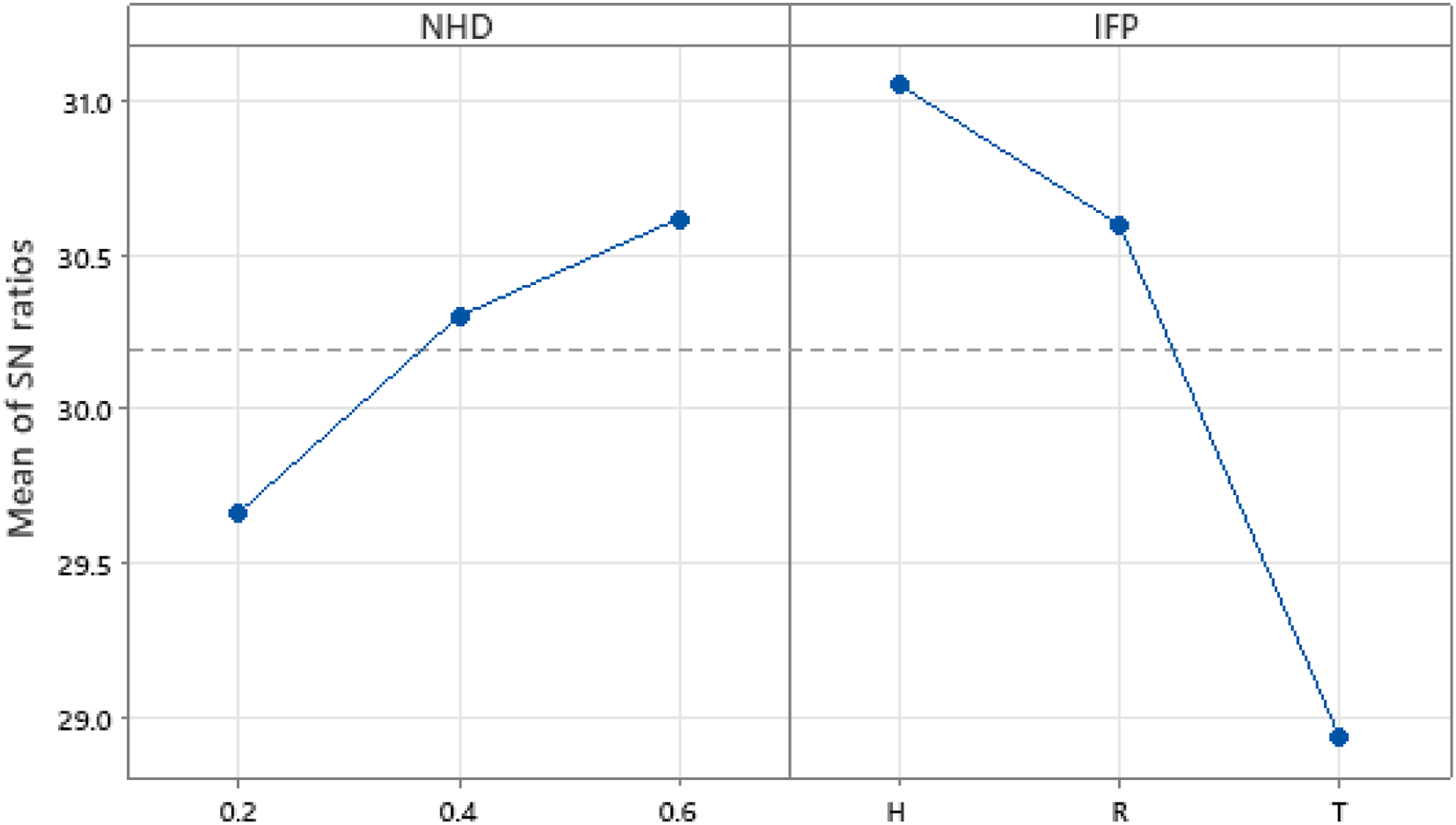
Taguchi analysis uses S/N ratio diagrams for data interpretation. As the determination of this study was to find the best combination of attributes, namely NHD, including 0.2 mm, 0.4 mm, and 0.6 mm, and IFP, including triangular (T), honeycomb (H), and rectilinear (R), to achieve the highest possible impact resistance, all S/N ratio diagram parameters were analysed using a “the larger, the better” criterion. The best scenario is depicted by the S/N ratio's peak point on the graph. Impact strength S/N ratio diagrams are shown in Figures 8, 10, and 12 for CF-PLA, CF-PETG, and MWCNTs-PLA specimens, respectively. The experimental results are examined using the MINITAB 21 programme. S/N ratio diagram for impact behaviour of CF-PLA specimens.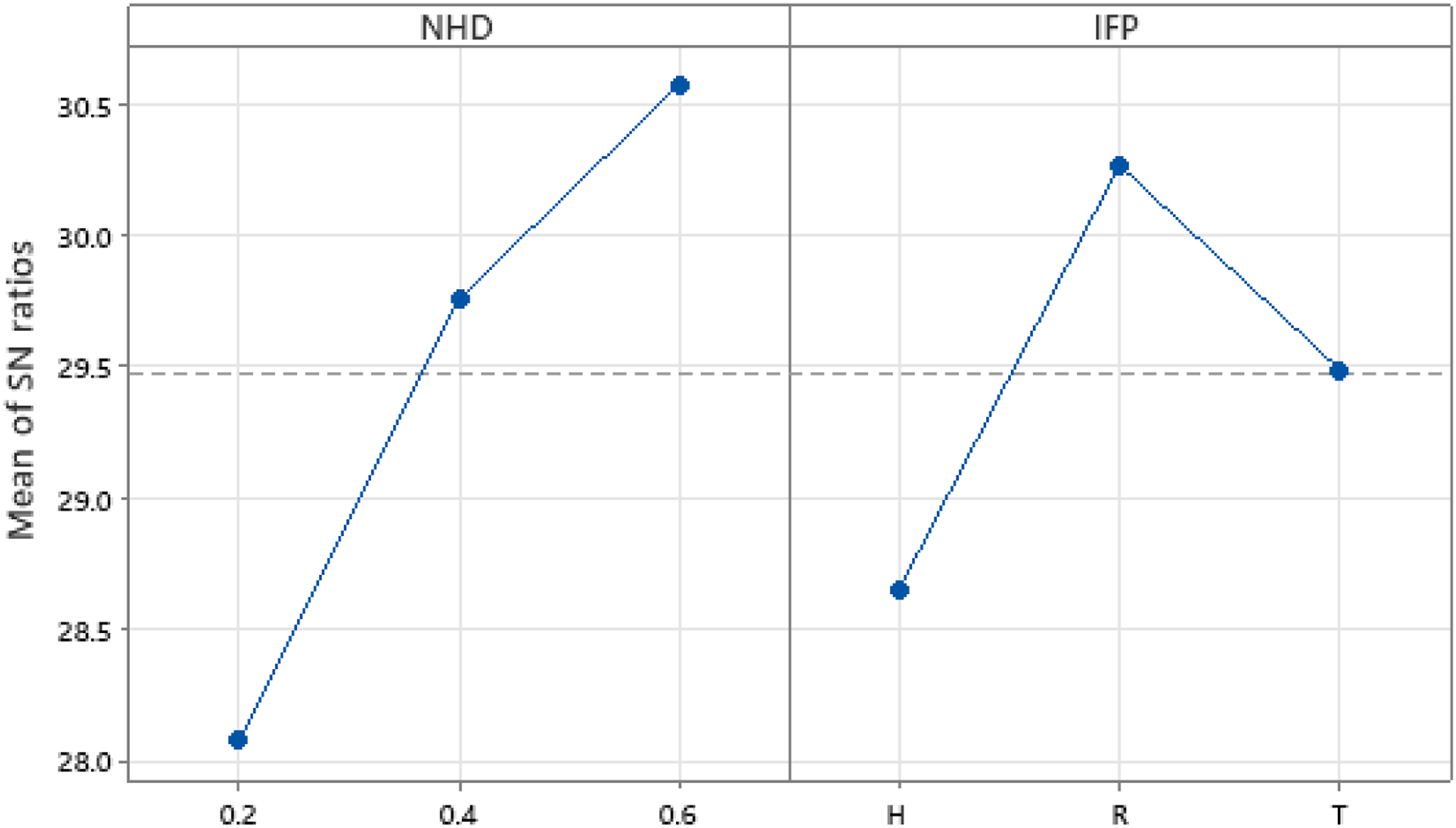
Carbon fibre reinforced poly-lactic acid
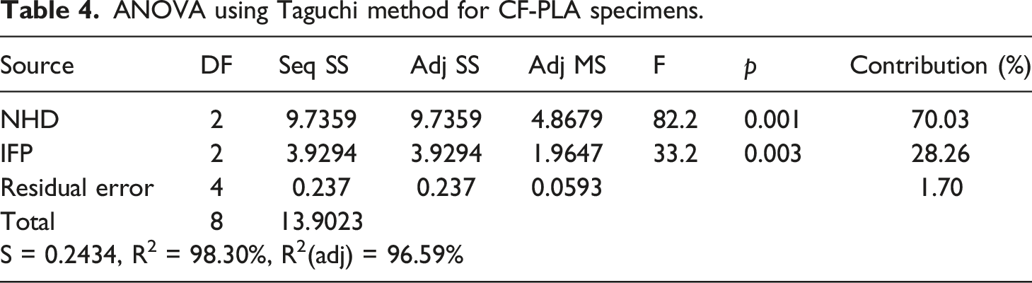
ANOVA using Taguchi method for CF-PLA specimens.
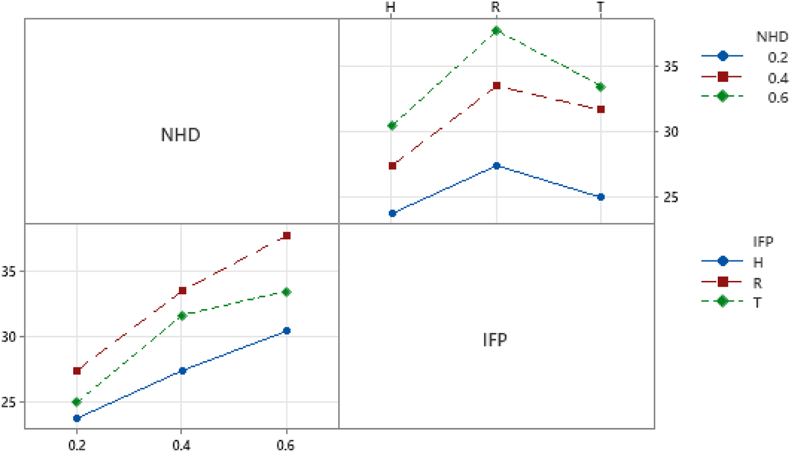
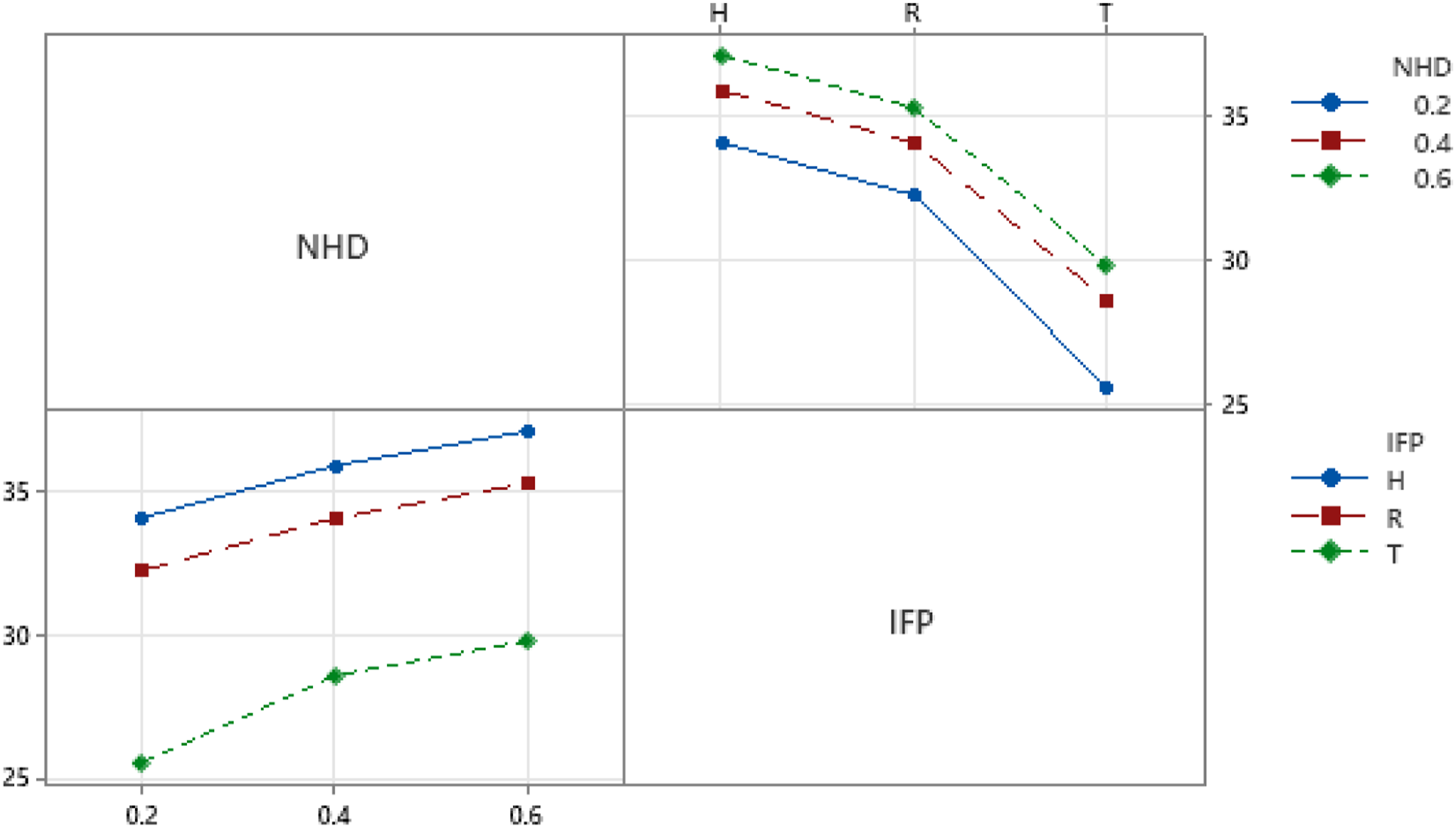
Interaction plot for impact behaviour of CF-PLA specimens.
Carbon fibre reinforced poly-ethylene terephthalate glycol
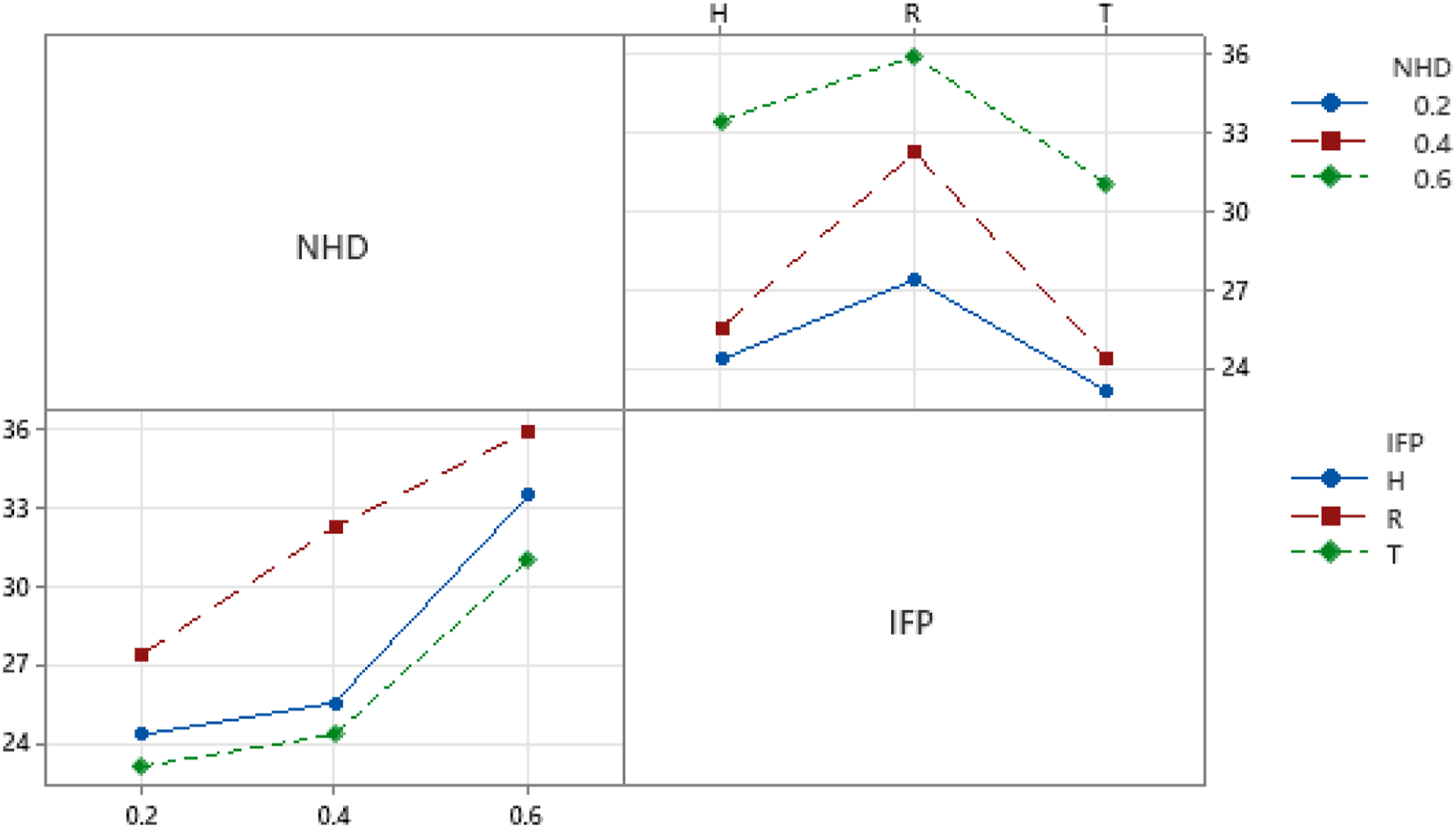
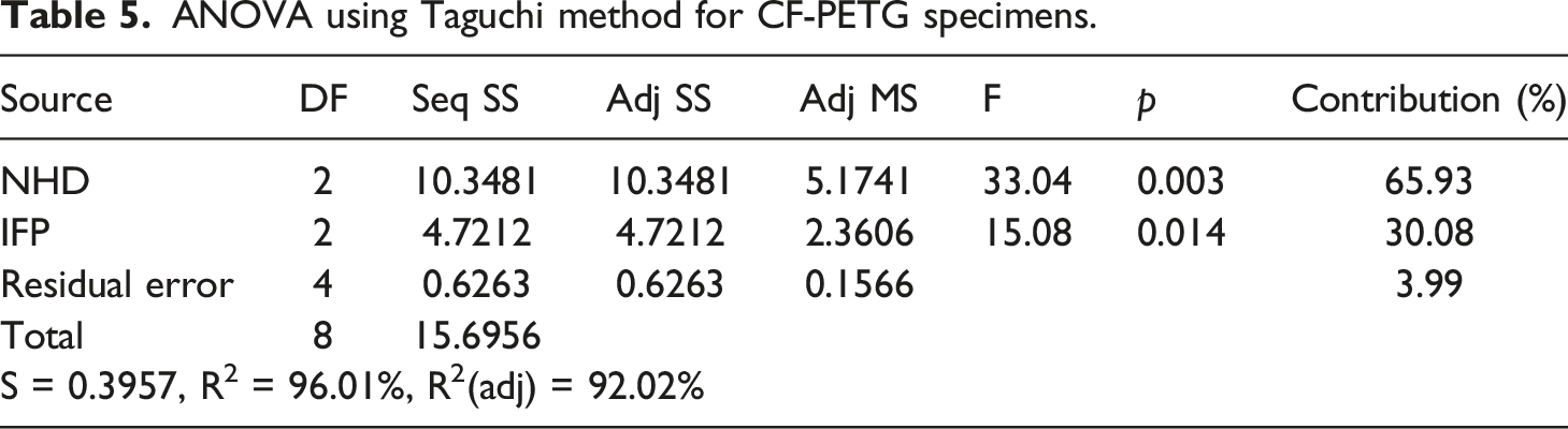
When comparing the impact behaviour at NHDs of 0.4 mm to 0.6 mm using Figure 10, it is clear that the 0.4 mm to 0.6 mm range experienced more variation. Since the raster-to-raster bonding improves. Thus, better impact behaviour is shown at greater NHD influence. When comparing rectilinear IFP to triangular and honeycomb IFP, rectilinear IFP is the best alternative for CF-PETG. NHD 0.6 mm and rectilinear IFP were found to be the best combination of parameters for maximising the impact resistance of the CF-PETG specimens. Based on Figure 11, It is evident that the NHD and IFP play a crucial role in determining how the CF-PETG specimens react to an impact. Based on the p-value from Table 5, NHD has the highest influence on impact strength for CF-PETG specimens, trailed by IFP with R2 value of 96.01%. While the IFP does play a role in print quality and strength, it is typically a secondary consideration compared to the NHD. The rectilinear IFP of CF-PETG specimens contributed to improved impact behaviour by allowing the load to distribute more evenly throughout the specimen, reducing the risk of localized stress concentrations with proper layer adhesion with NHD 0.6 mm. S/N ratio diagram for impact behaviour of CF-PETG specimens. Interaction plot for impact behaviour of CF-PETG specimens. ANOVA using Taguchi method for CF-PETG specimens.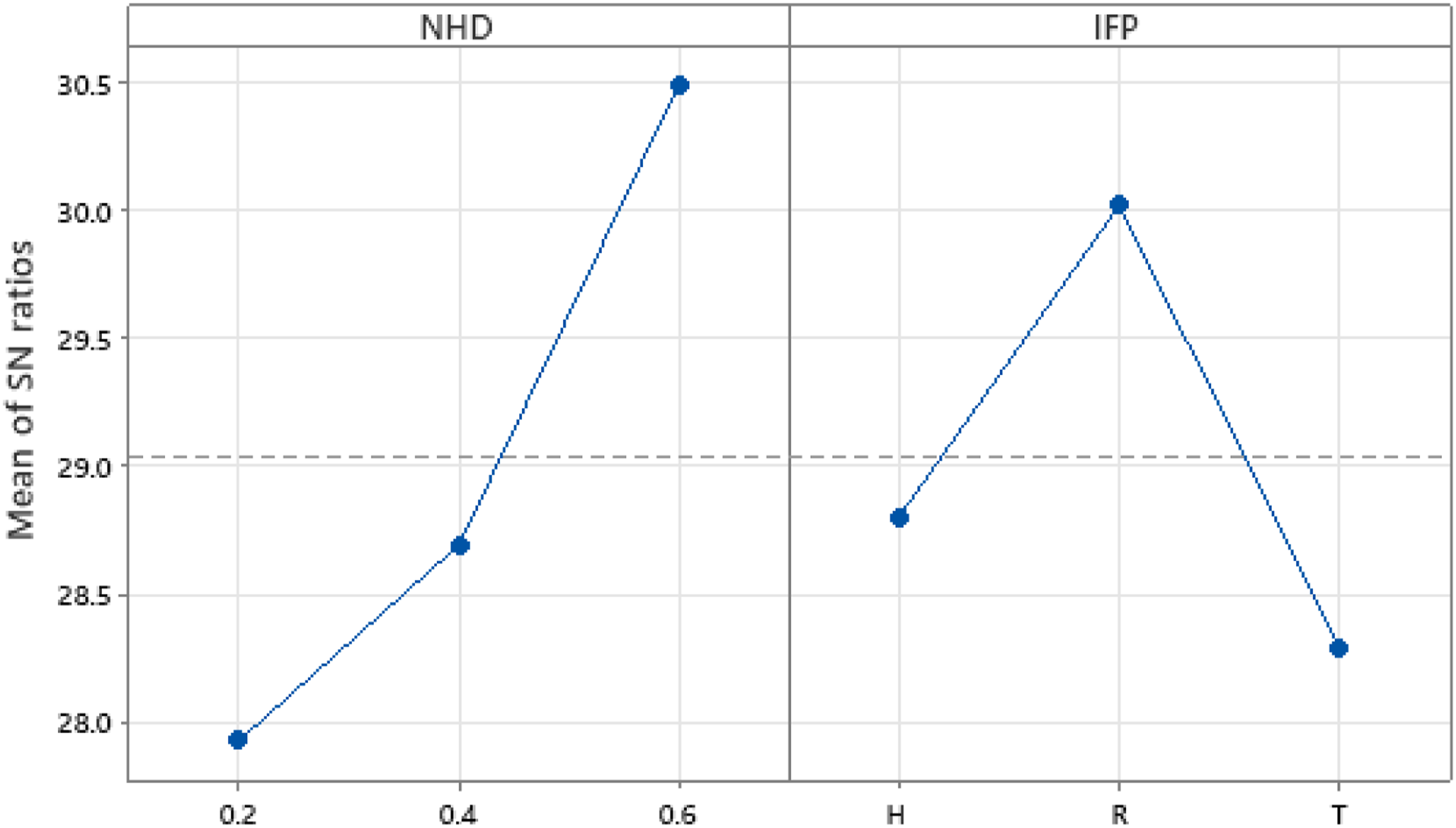
Multi walled carbon nano tubes reinforced poly-lactic acid
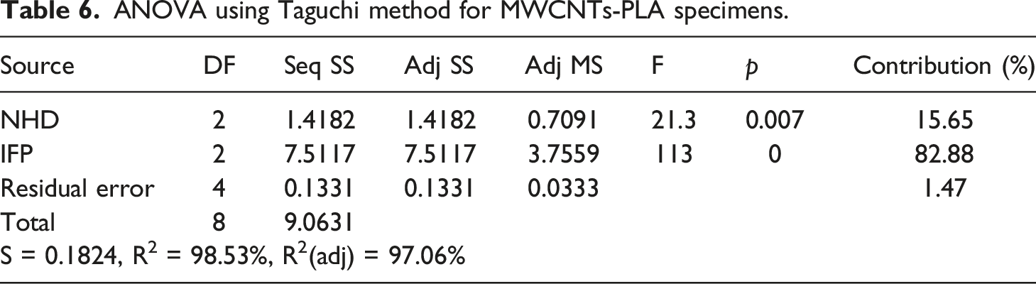
ANOVA using Taguchi method for MWCNTs-PLA specimens.
S/N ratio diagram for impact behaviour of MWCNTs-PLA specimens.
Interaction plot for impact behaviour of MWCNTs-PLA specimens.
ANOVA with response surface method
This study also used a response surface method statistical technique for its design of experiment. MINITAB 21 was utilised for the statistical analysis. The software's primary function is to conduct statistical assessment of the influence of selected parameters on the impact behaviour of produced polymer composites. This research used a 95% confidence interval to establish the significance of the influence of the IFP and NHD. In statistical terms, this corresponds to an alpha value of 0.05. On the other hand, this response surface methodology can be utilised to model and analyse problems, as well as enhance results via the model created. Overarchingly, the goal of analysis is to find the optimal value for a set of inputs that enhances impact strength (IS).
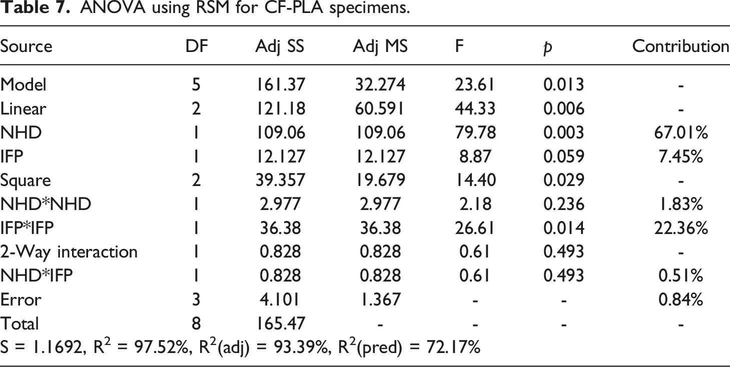
The ANOVA was performed to find the relative importance of the various input process parameters and their effect on the final outcome of the experiment. Adjusted sum of squares (Linear (NHD, and IFP), Square (NHD × NHD, and IFP × IFP), and 2-way interaction (NHD × IFP)) were used to determine what percentage of variation in each input process parameter resulted in the observed variation in the response. For regression analysis, the values used for IFP are 1, 2, and 3 for triangular, honeycomb, and rectilinear, respectively.
Carbon fibre reinforced poly-lactic acid

ANOVA using RSM for CF-PLA specimens.
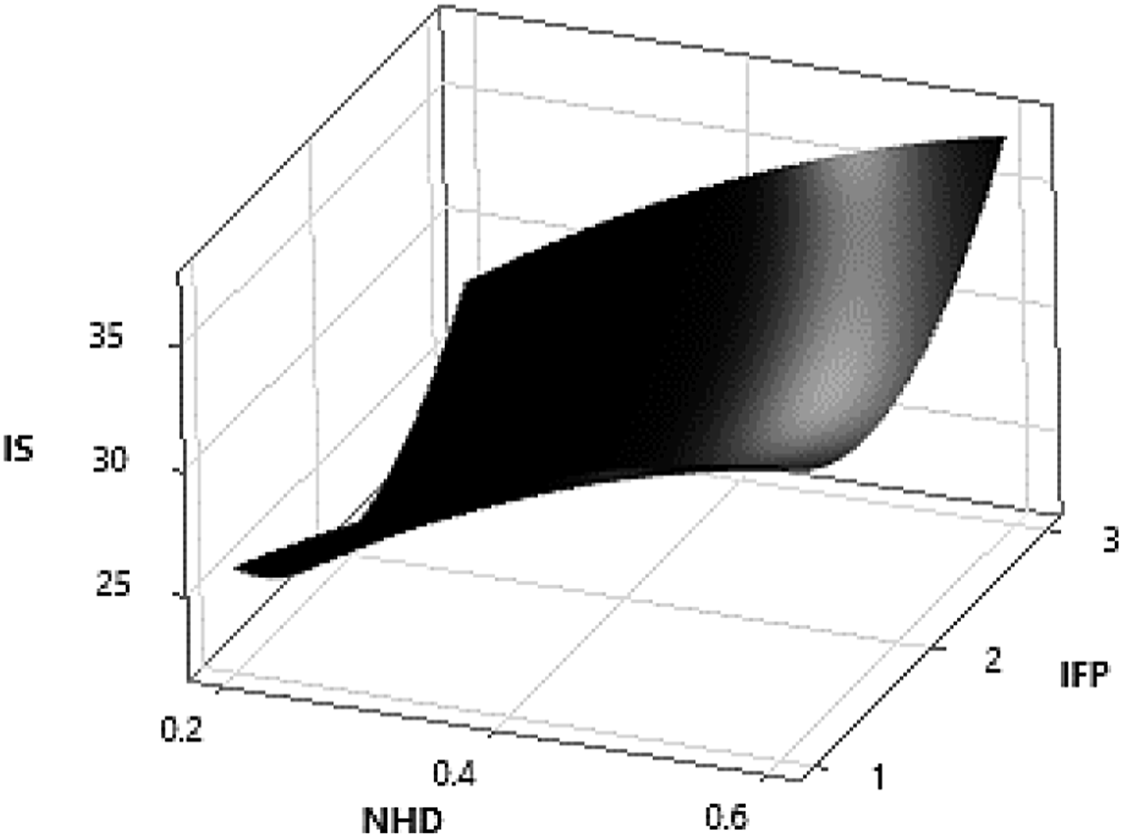
Surface plot for impact behaviour of CF-PLA specimens.
Carbon fibre reinforced poly-ethylene terephthalate glycol

ANOVA using RSM for CF-PETG specimens.
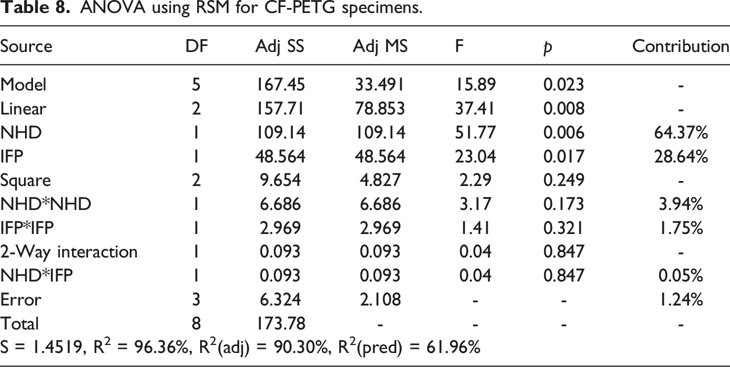
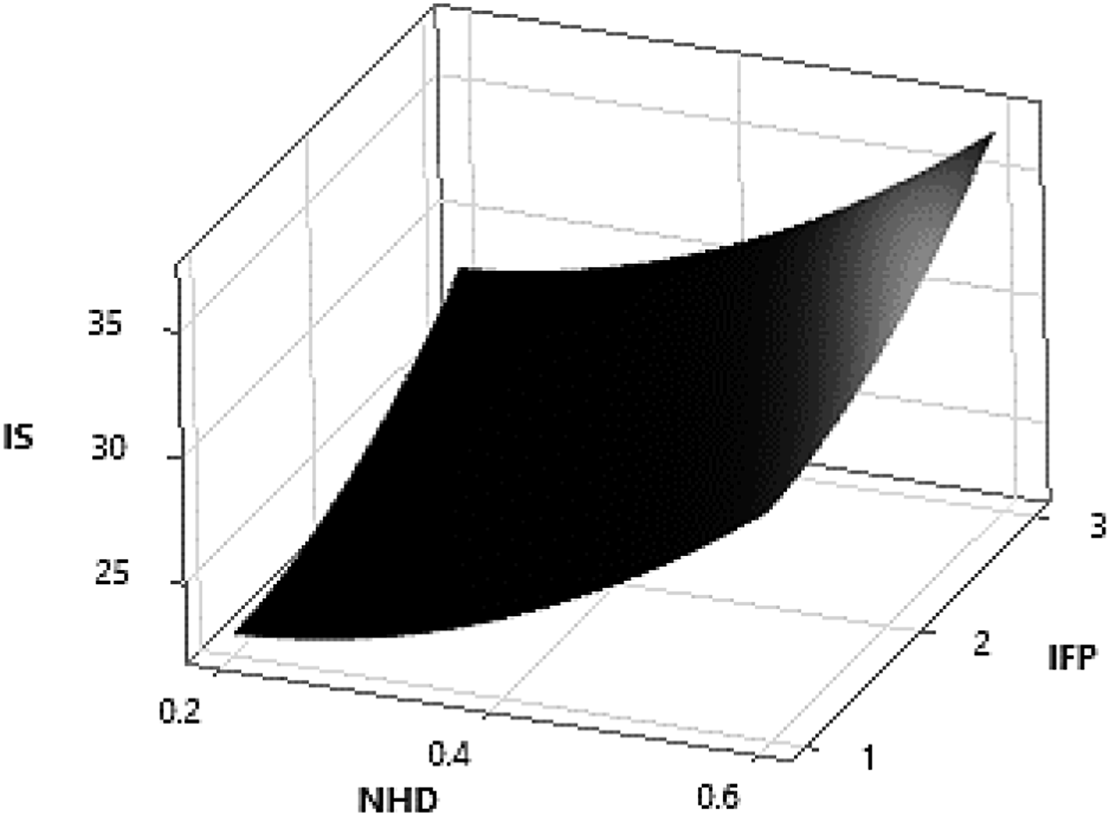
Surface plot for impact behaviour of CF-PETG specimens.
Multi walled carbon nano tubes reinforced poly-lactic acid

ANOVA using RSM for MWCNTs-PLA specimens.
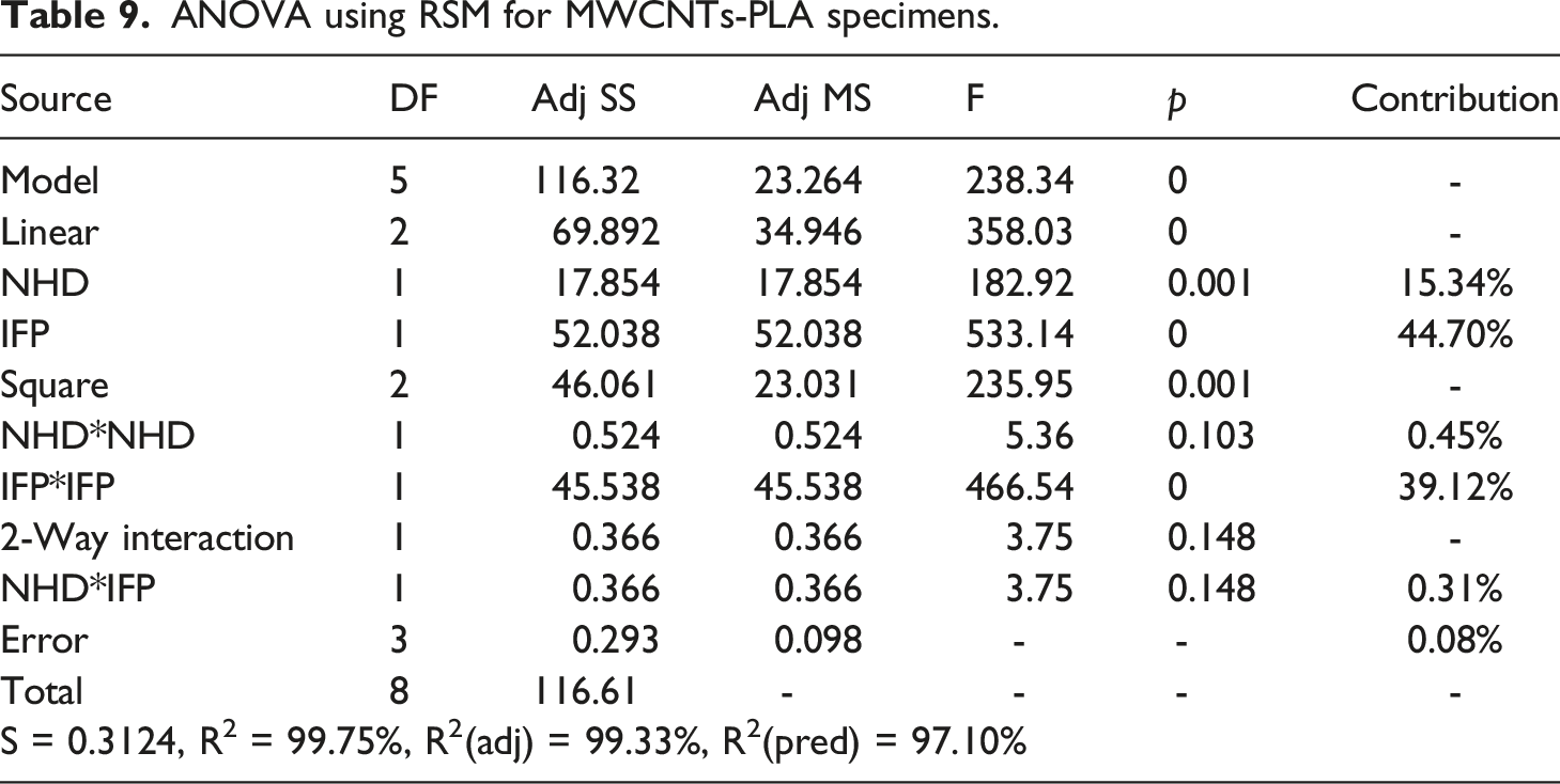
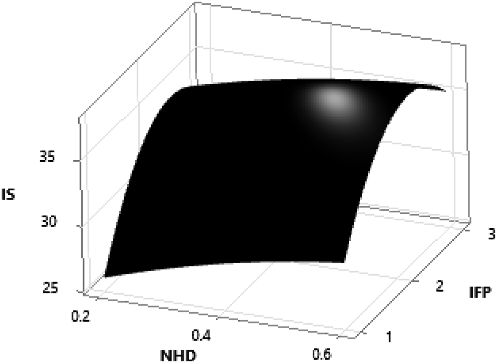
Surface plot for impact behaviour of MWCNTs-PLA specimens.
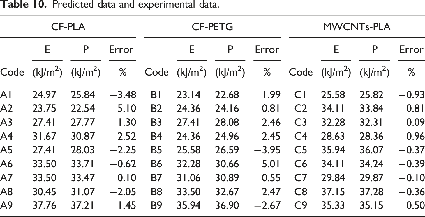
Predicted data and experimental data.
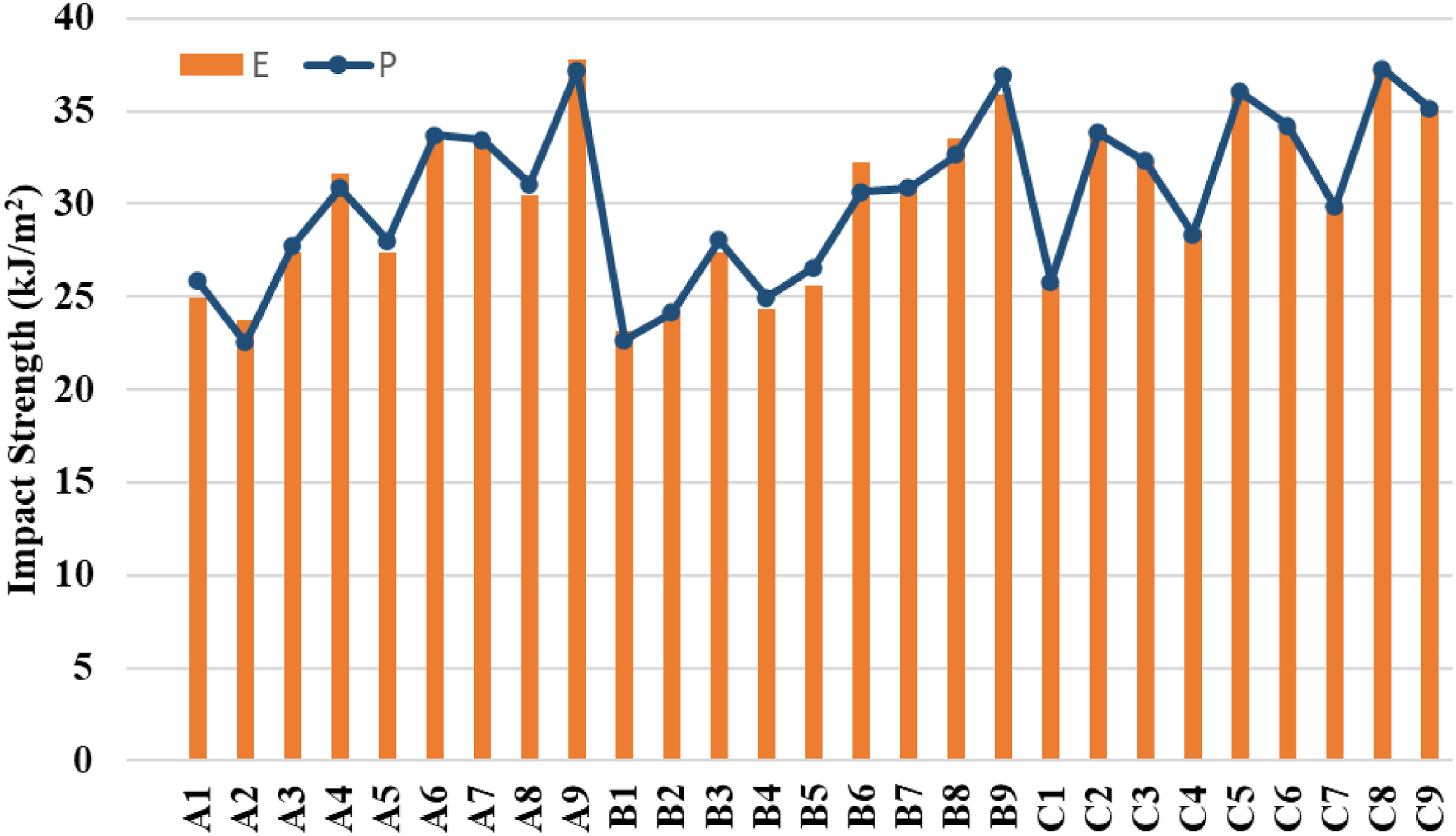
Experimental vs Predicted impact strength variation.
The statistical analysis performed using Taguchi method and RSM for the impact behaviour of polymer composites in the present work. Both techniques exhibit similar outcome for the effect of NHD and IFP to the impact strength while having significant level above 95%. At NHD 0.6 mm and rectilinear IFP, the CF-PLA specimen accomplishes a maximum impact strength of 37.76 kJ/m2. It is 175% more than the results stated by Atakok et al., 42 who observed the impact strength of pure PLA 13.7 kJ/m2 for same layer height and IFP. The impact strength of a material is measured to ascertain whether, when subjected to suddenly imposed loads, the material will behave in a brittle or ductile manner.
Conclusion
In summation, this research work yielded a wealth of knowledge and understanding about the mechanics of anisotropic FFF components. Major takeaways from the research are as follows:
The minimum flexural strength achieved is 21.079 MPa at a NHD of 0.2 mm and using a IFP for MWCNTs-PLA. Conversely, the maximum flexural strength obtained is 70.653 MPa at NHD 0.6 mm and employing a rectilinear IFP for MWCNTs-PLA. Consequently, the flexural strength is boosted by 235.18% by the manipulation of the chosen process parameters. This study's findings suggest that careful IZOD testing is a reliable way for evaluating the mechanical behaviour of FFF-fabricated materials. The material's fracture characteristics are profoundly influenced by the IFP and NHD of the during the fabrication of the specimens. The impact resistance is enhanced with increasing NHD. Impact behaviour of FFF-fabricated specimens is directly influenced by IFP. The honeycomb IFP exhibits the highest impact strength for MWCNTs-PLA specimens, whereas the rectilinear IFP is best for CF-PLA and CF-PETG specimens.
The statistical investigation utilising the Taguchi method and RSM of polymer composite impact behaviour exhibited similar results for the influence of NHD and IFP on impact strength, with significant levels above 95%. On analysing the variation in impact strength, IFP is the primary contributor for MWCNTs-PLA specimens, but for CF-PLA and CF-PETG specimens, the primary contribution is NHD. Modifying a process parameter has different effects on the target factor depending on the material being used to make it. At NHD 0.6 mm and rectilinear IFP, the CF-PLA specimen accomplishes the highest impact strength of 37.76 kJ/m2 due to adequate pulling and necking, primarily resulting in the breaking of raster and CFs.
Footnotes
Acknowledgements
Support from FESEM lab., Department of Chemistry, DEI is highly appreciated for fractography analysis. We are also thankful to the grant received from AICTE (file no. 8-88/FDC/RPS (POLICY-1)/2019-20).
Declaration of conflicting interests
The author(s) declared no potential conflicts of interest with respect to the research, authorship, and/or publication of this article.
Funding
The author(s) received no financial support for the research, authorship, and/or publication of this article.