
Abstract
Conductive polymer composites (CPCs) are manufactured by compounding conductive particles with a polymer matrix. There are many applications where they are used, including light-weight applications requiring both electrical and heat conductivity. Carbon nanotubes (CNTs) have been accepted as common materials to accomplish this goal. As part of this research, a material extrusion additive manufacturing (AM) process was utilized to create nanocomposites by a 3D-printing technique. Multi-wall carbon nanotubes (MWCNTs) were mixed in 1, 3 and 6 wt fractions with acrylonitrile butadiene styrene (ABS) and extruded in filament form. Three-dimensionally printed specimens were used to evaluate electrical, electromagnetic interference shielding effectiveness (EMI SE) and tensile properties. The electrical conductivity of the material was 26 times greater than that of ABS. In the X-band of electromagnetic waves, EMI SE's reflected and absorbed portions increased respectively 4 and 16 times. The tensile strength and modulus were enhanced by 15% and 9%, respectively. On composite specimens, microwave heat treatment was applied. There is less void space between the rasters and layers, which helps improve tensile properties. Additionally, 3D-printed specimens were tested for melt flow rate (MFR) and dynamic mechanical behaviour. The nozzle has experienced some wear due to the intrinsic abrasive nature of CNTs.
Keywords
Highlights
• Electromagnetic interference shielding is improved by CNT due to its high electrical conductivity. • CNT concentrations of 3 wt% had the highest strength and tensile modulus. • Mechanical properties were improved only slightly by microwave heat treatment. • There has been some wear in the nozzle of the 3D printer as a result of CNT abrasion.
Introduction
Conductive polymer composites (CPCs) are an emerging class of lightweight and easy-to-fabricate materials. Insulating polymers are filled with conductive materials like metal powder/fibre,1–3 CNT,4–7 graphene, 8 carbon black, 9 and CF. 10 Due to their similar density range to polymers, CNTs and graphene are more interesting carbonaceous fillers. Their mechanical and electrical properties are also impressive. Thermal conductivity is also enhanced by these fillers. When microelectronic devices need to be thermally managed, this property is of prime importance. 11 CPCs can be applied in areas of strain sensors, 12 and temperature sensors. 13
CPCs are widely used due to their electrical conductivity. In case a sufficiently interconnected network of conductive fillers is formed in a composite, the composite will behave in the same way as a conductor. Almost every CPC has a minimum weight fraction of filler, which is intrinsic to the material, after which the material transitions from being an insulator to a conductor all at once. Depending on the aspect ratio of the filler and dispersion state in the matrix, this is called the percolation threshold. 14
Several sensitive systems are susceptible to interference caused by electromagnetic waves emitted by electronic devices. Metal sheets are fundamentally the best materials for electromagnetic interference (EMI) shielding, but some radiation may leak into the enclosure's seams. CPCs are promising materials for EMI shielding due to their reasonable electrical conductivity (EC), low cost, and variety of fabrication methods.15,16 In general, the higher the EC of CPCs, the more EMI shielding is preserved. A heat treatment that increases the electrical conductivity of injection-molded CNT-based CPCs can also significantly increase EMI shielding. 17 Hybrid CPCs containing MWCNT/graphene nanoplatelets have synergic EMI shielding properties for injection-molded polycarbonate (PC)/ABS. 18 Hollow silver-cobalt microspheres were used to enhance the microwave absorption of polydimethylsiloxane/carbon nanotube composites. 19 The unique conductivity of the CNT/CNT-cluster network formed in the polylactic acid matrix (PLA) significantly improved the shielding performance. 20 The thickness and filler content of the middle layer of a sandwich structure can be adjusted to regulate shielding. 21
Fused deposition modeling (FDM) is one of the lowest and most widespread AM methods and is employed in rapid prototyping (RP) and/or rapid tooling (RT). 22 Thermoplastic filaments such as PLA, ABS, polyamide and polycarbonate are extruded into a hot nozzle, melted and deposited layer by layer on a bed. Using a slicer, a digital model is converted to a command file (G-code) in accordance with printing parameters, such as layer height, nozzle temperature, speed, etc. The properties of 3D-printed parts can be altered by adding a variety of materials to pure polymers. Compounding short glass fiber (GF) 23 and CF24,25 with a polymeric matrix and extruding it as composite filament yields higher mechanical properties.
There have been numerous studies of 3D printing with CPCc to explore their thermal, electrical, and mechanical properties. In recent years, syringe-based 3D printers have exploited the intrinsic strength of thermoset resins against temperature. Although curing and dimensional stability remained challenges for the 3D printed parts.26,27 Polyvinyl alcohol (PVA) was melt-mixed with different CNT concentrations and extruded into nanocomposite filaments. The resistivity of bulk material decreased as CNT loading increased, but it remained constant for 3D-printed parts. 28 FDM parts and commercial composite filament were compared in terms of their resistivity in two fillers graphene and CB. 29 Poly (vinylidene fluoride)/MWCNT composites have been investigated for the detection of volatile organic chemicals (VOCs). 30 An innovative dip coating of PLA scaffolds produced segregated PLA/CNT composites. The results were compared to the conventional method of mixing solution. A significant improvement in EMI shielding, electrical conductivity, and bending strength was achieved. 31
Commercial ABS/Graphene filaments have been utilized in FDM. Electrical tests revealed that their conductivity is similar to semiconductors. 32 The 3D printing of ABS/MWCNT composites was studied at two raster angles 0/90° and +45/-45°, with three layer heights. In contrast to the less effective printing angle, the tensile strength decreased with increasing thickness. 33 The piezoresistive properties of ABS/CNT composites were investigated using 3D printing. When CNT was 5%, a linear piezoresistive behavior was observed and the gauge factor was near 2. 34 3D-printed polypropylene random copolymer/MWCNT nanocomposites exhibit EMI shielding effectiveness (SE) depending on their printing direction. As a result of the lower void content of the raster angle of 90°, there was a higher EMI SE. 35
As a result of the interlayer voids in FDM parts, they have lower mechanical properties than injection-molded parts. Assistive heating and post-annealing improve mechanical and electrical properties. 36 When microwaves are irradiated on CNTs, they produce a local rise in temperature. As a result, the void formed during printing between rasters and layers is collapsed. This enhances mechanical strength and electrical conductivity. 37
Research on 3D printing of CPCs is ongoing, and its application in different sectors requires a deeper understanding of their properties. Literature contains many research papers about some of the applications and characteristics. The purpose of this paper is to study some aspects of rheology, printability, mechanical, electrical, and EMI shielding properties. In this experiment, composite filaments were manufactured and parts were 3D-printed using the FDM method.
Materials and methods
Materials
In this research, ABS grade N70 supplied from iTech Polymer Co. (Iran) with a melt flow index (MFI) of 10 g/10 min measured by ASTM 1238 (10 kg at 220°C) was utilized as the polymer matrix. ABS is an amorphous and common polymer in FDM. MWCNTs are selected as conductive fillers. It has a purity of 95%–99%, a diameter of 10-20 nm and a 10 μm length, made by Iran.
Composite filament fabrication
Since ABS absorbs a lot of humidity, it should be dried in an oven for 3 h at 80°C. To prepare the polymeric composite, the melt mixing method was employed. An internal mixer was designed and manufactured by our research group with a capacity of 60 mL. To achieve better dispersion, the blades were rotated at a 3:2 ratio. Rotation speed was 30 r/min and mixing temperature was 220°C. The chamber was first filled with 1/2 of its capacity of ABS granules and melted, and then CNTs were added. As soon as the ABS granules were mixed, the remaining granules were added to the mixer chamber. Every sample was mixed for 5 min. In this study, composites contained 1, 3, and 6 wt percentage % (wt%) of CNT. ABS, ABS1C, ABS3C, and ABS6C are the codes for pure ABS and its corresponding CNT content. The number after ABS and before C indicates the weight percent of CNT. Feedstock was purged from the mixer, flattened, and broken into small pieces. A single screw extruder with a diameter of 45 mm and a length-to-diameter ratio (L/d) of 30 was utilized. The four heating zones of the extruder were adjusted to 150, 195, 195 and 195°C. The orifice die diameter was 1.8 mm. For better dispersion of CNTs in the composite filament, the extruded filaments were crushed and re-extruded again. The speeds of extrusion and haul-off were adjusted to obtain a filament with a diameter of 1.75 ± 0.1 mm suitable for FDM.
3D printing composite specimens
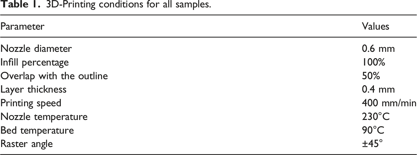
3D-Printing conditions for all samples.
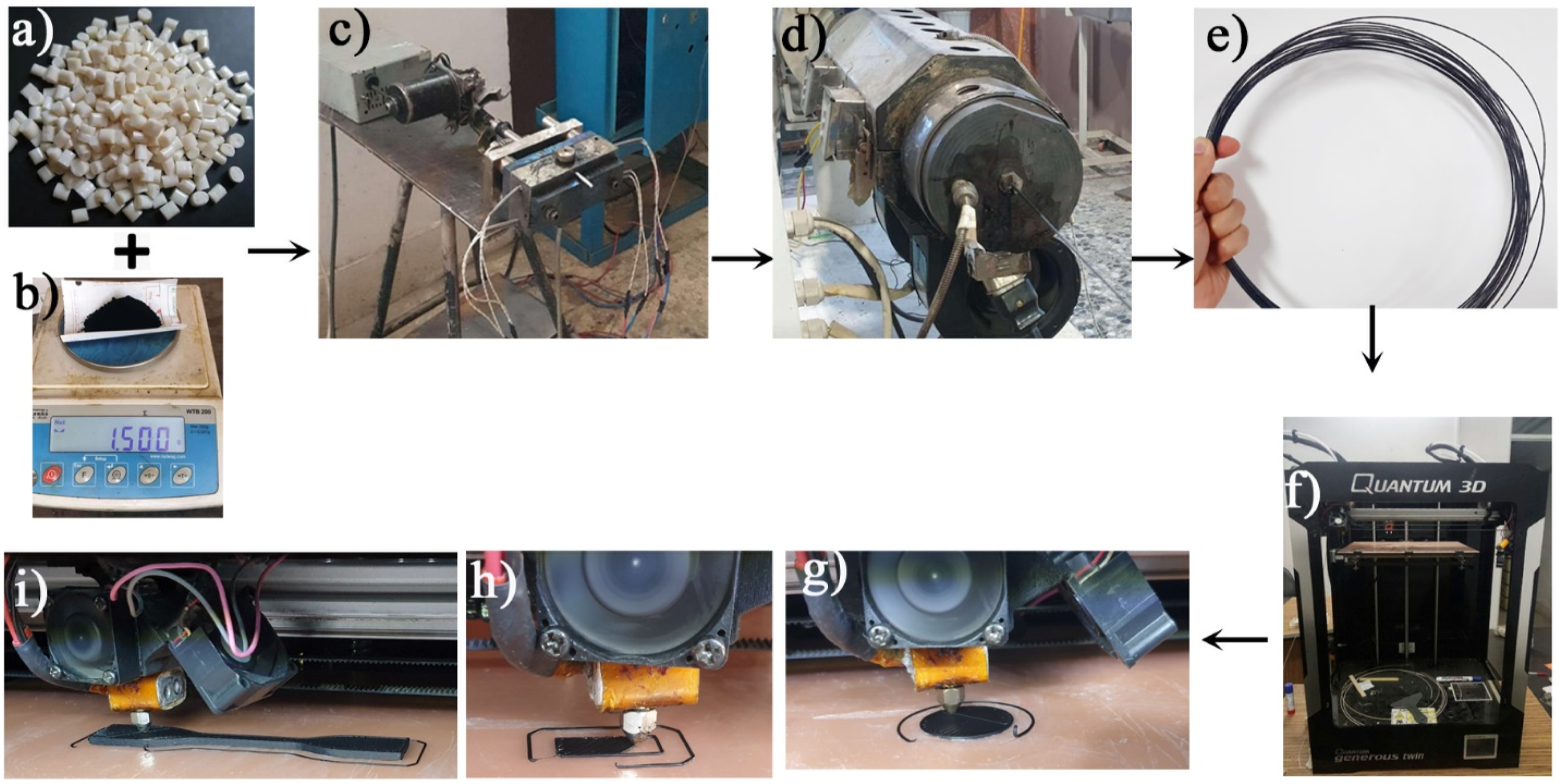
(a) ABS granule; (b) CNT; (c) internal mixer; (d) single screw extruder; (e) composite filament; (f) 3D-printer; 3D-printing (g) electrical test, (h) dynamic mechanical analysis and (i) tensile tests.
Electrical conductivity test
A Keithley 610C solid-state electrometer was utilized for direct current (DC) electrical conductivity measurement. Circular samples were printed with a diameter of 25 mm (electron transfer area of 490.8 mm2) having a thickness of 2 mm, as shown in Figure 1(g). A 2-probe test was conducted according to ASTM D257. The electrical conductivity of samples was measured in the thickness direction.
EMI shielding test
As electromagnetic waves propagate into conductive materials, they are attenuated. The EMI SE of 3D-printed samples was evaluated using an Agilent E8362 B network analyzer per ASTM D4935. Rectangular parts with dimensions of 22.5 × 10 × 2.5 mm were printed. This study focused on X-band electromagnetic waves (8.2-12.4 GHz). The measurements were conducted from the thickness direction, similarly to the conductivity test. In radars, satellite communications, and wireless networks, X-band is commonly used. EMI SE can be determined by equation (1):
The transmission (T), reflector (R) and absorption (A) factors are determined as:


Tensile test
Tensile test specimens were modelled according to ASTM D638 (type IV) with a gauge length of 65 mm. The tensile modulus was calculated from the slope of the stress-strain curve up to strain 1%. The tensile tests were repeated three times on each specimen, and the average and standard deviation are reported. There may be differences in dimensions between printed components and designed models. Prior to each test, the real dimensions of the parts were measured with a digital calliper. A universal testing machine, made by Iran, Santam, STM-20 equipped with a load cell of 20 kN was employed for tensile tests. The printing speed was set to 4 mm/min. Figure 2 shows fractured specimens in a tensile test. Fractured (a) pure ABS and (b) ABS1C in tensile test.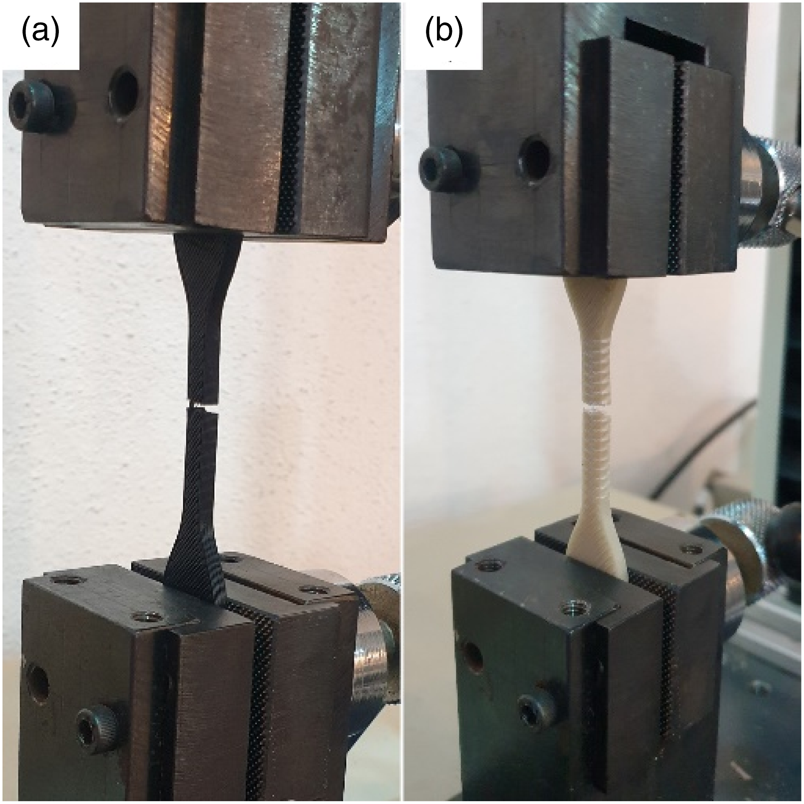
Microwave heat treating
For microwave post-processing of tensile test specimens, a kitchen microwave with 600 W was chosen. In this study, three samples ABS, ABS1C, and ABS3C were exposed for 2 minutes. Tensile tests were performed on the post-processed specimens and compared to their non-heated counterparts.
Scanning electron microscopy
After the tensile test, fractured surfaces of the specimens were evaluated with an SEM machine (SNE-4500M). Using a Polaris coating machine, all samples were coated with gold before SEM. SEM was also used to measure the inside diameter of the nozzle after 3D printing in order to evaluate the abrasiveness of CNT.
Melt flow rate test
With the addition of CNT, ABS material will have a higher viscosity. An influential property for evaluating filament suitability for FDM is the melt flow rate (MFR) or melt flow index (MFI). Printing can be difficult with a lower MFR due to clogging of the extruder nozzle. Filaments were granulated into small pieces and put in a melt flow indexer. As per ASTM D1238, the melt temperature was 230°C with a mass of 10 kg.
Dynamic mechanical analysis
Under dynamic loads, it is imperative to understand the dynamic mechanical properties of parts. A dynamic mechanical analyzer (Triton, England) was employed. A sample with dimensions 22.5 × 10 × 2.5 mm (similar to EMI shielding tests) was tested in 3-point bending mode with a frequency of 1 Hz. Temperature ranges were between 25°C and 130°C with a heating rate of 5°C/min.
Results and discussions
Electrical conductivity
Figure 3 shows that a high CNT content increases electrical conductivity. Electron tunnelling effects between every CNT particle and its neighbours in the ABS matrix increased electrical conductivity.
39
By adding 6% CNT to the ABS, its electrical conductivity increased 26 times. However, the expected conductivities were not achieved.40,41 effect of CNT content on the volume conductivity.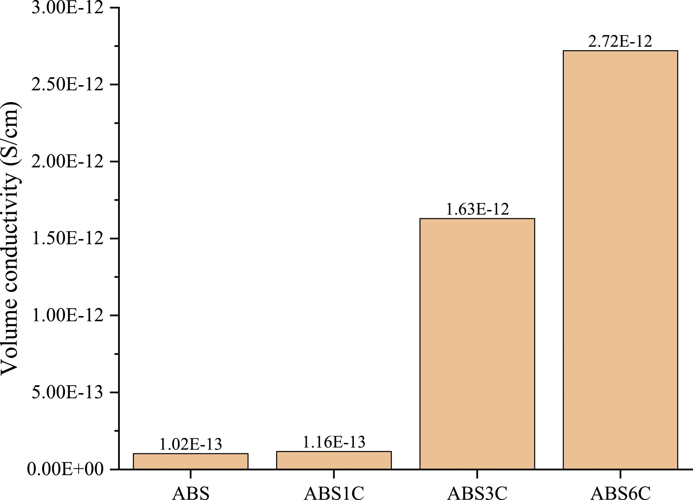
EMI shielding
The reflected and absorbed components of EMI SE are shown in Figure 4(a) and (b), respectively. In general, the higher the CNT content, the more electromagnetic waves are attenuated. For composites containing 6 wt% CNT, when a valley occurs in the reflected curve at a certain frequency, there is a peak at the corresponding frequency in the absorbed curve. Curves appear to plateau at higher frequency ranges. The averages and standard deviations of two portions of the attenuation mechanisms are illustrated in Figure 4(c). All specimens displayed superior reflective properties over absorbed ones. (a) reflected and (b) absorbed portion of shielding versus X-band frequency; (c) averages of each component of shielding.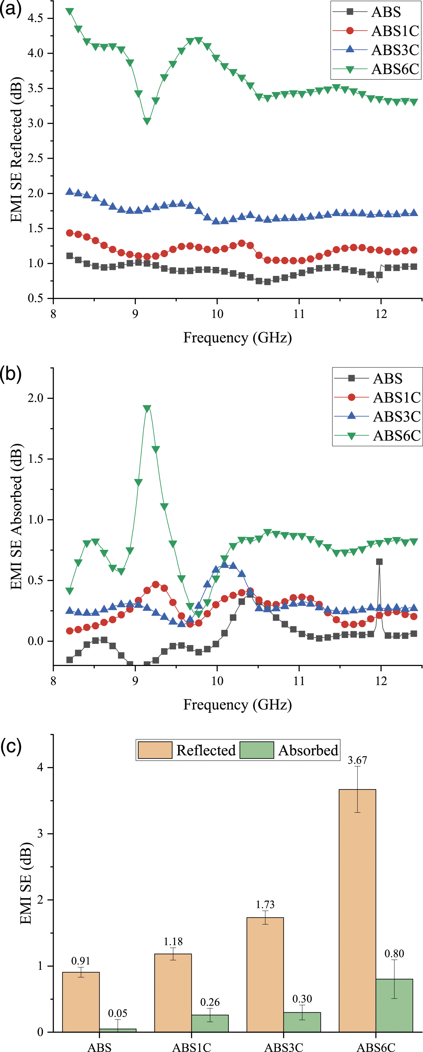
Tensile properties
The effects of CNT content and microwave heat treatment on tensile behavior are shown in Figure 5. The tensile strength of composite specimens increased up to 3 wt% of CNT and then decreased (Figure 5(a)). This decrease can be attributed to the agglomeration of CNT particles within the polymeric matri.
42
As shown in Figure 5(b), tensile modulus followed a similar trend. Figure 5(c) shows the stress-strain curves for all the samples. By adding 3% of CNT particles, they increased the tensile strength and Young’s modulus to 35.69 MPa and 1949.76 MPa, respectively. Also, the curves indicate that with increasing CNT, the strain at fracture and therefore the ductility was reduced as illustrated in Figure 5(d). tensile (a) strength and (b) modulus for different CNT content and microwave conditioning; (c) stress-strain curves obtained from tensile tests; (d) failure strains of specimens.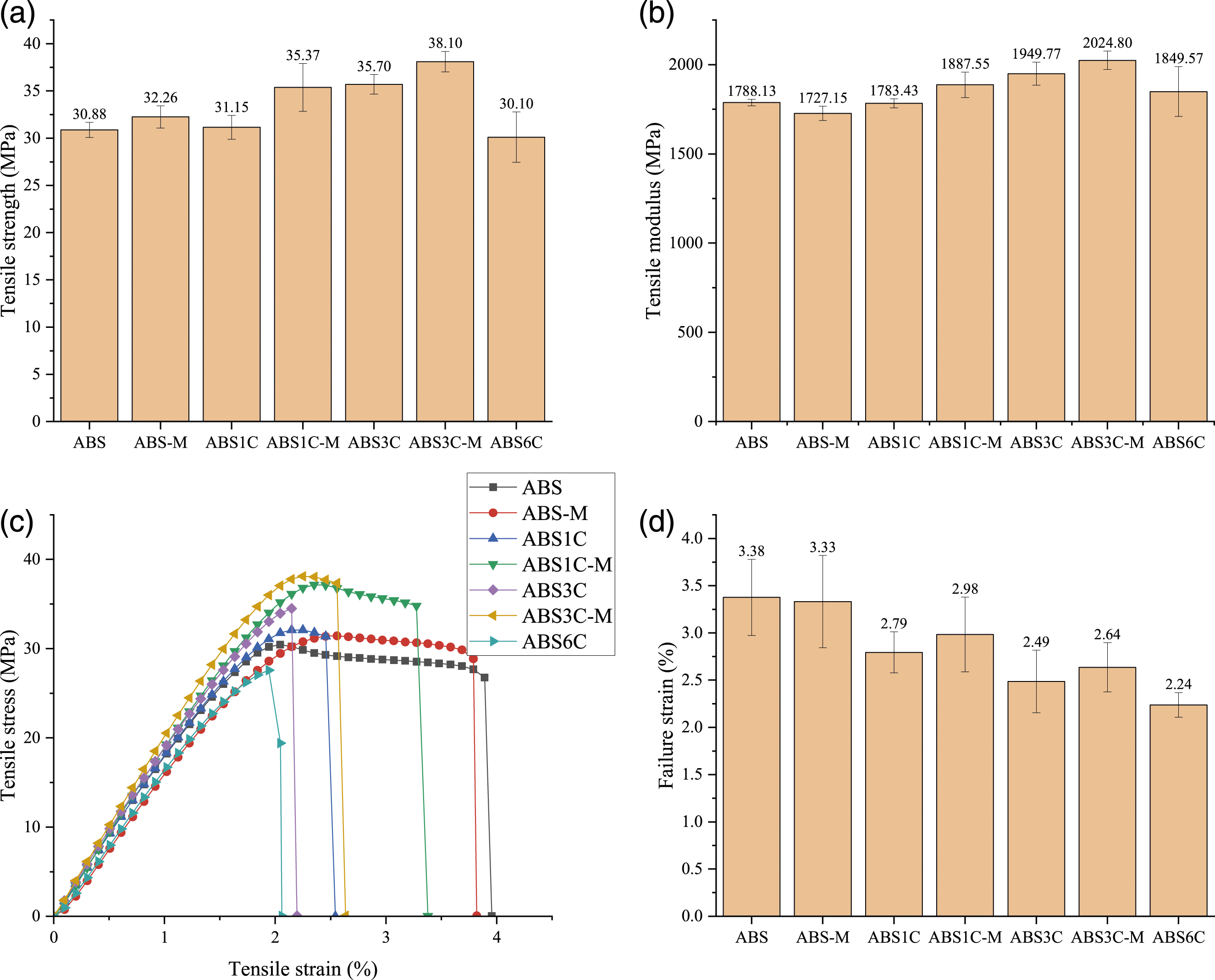
Figure 5 also shows microwave heat treatment results. It demonstrated that this type of heat treatment intensifies mechanical properties. This improvement is attributed to the lower voids formed between the rasters and layers by heat treatment. The CNTs absorb microwaves and convert them into heat. In consequence, ABS will become softer and the space between rasters will become smaller. Figure 6 shows the SEM images of the fractured cross-section of all specimens in the tensile test. For microwaved samples, the rasters overlap a little more, resulting in marginally improved tensile properties. SEM of samples for (a) ABS, (b) ABS-M, (c) ABS1C, (d) ABS1C-M,)e) ABS3C,)f) ABS3C-M.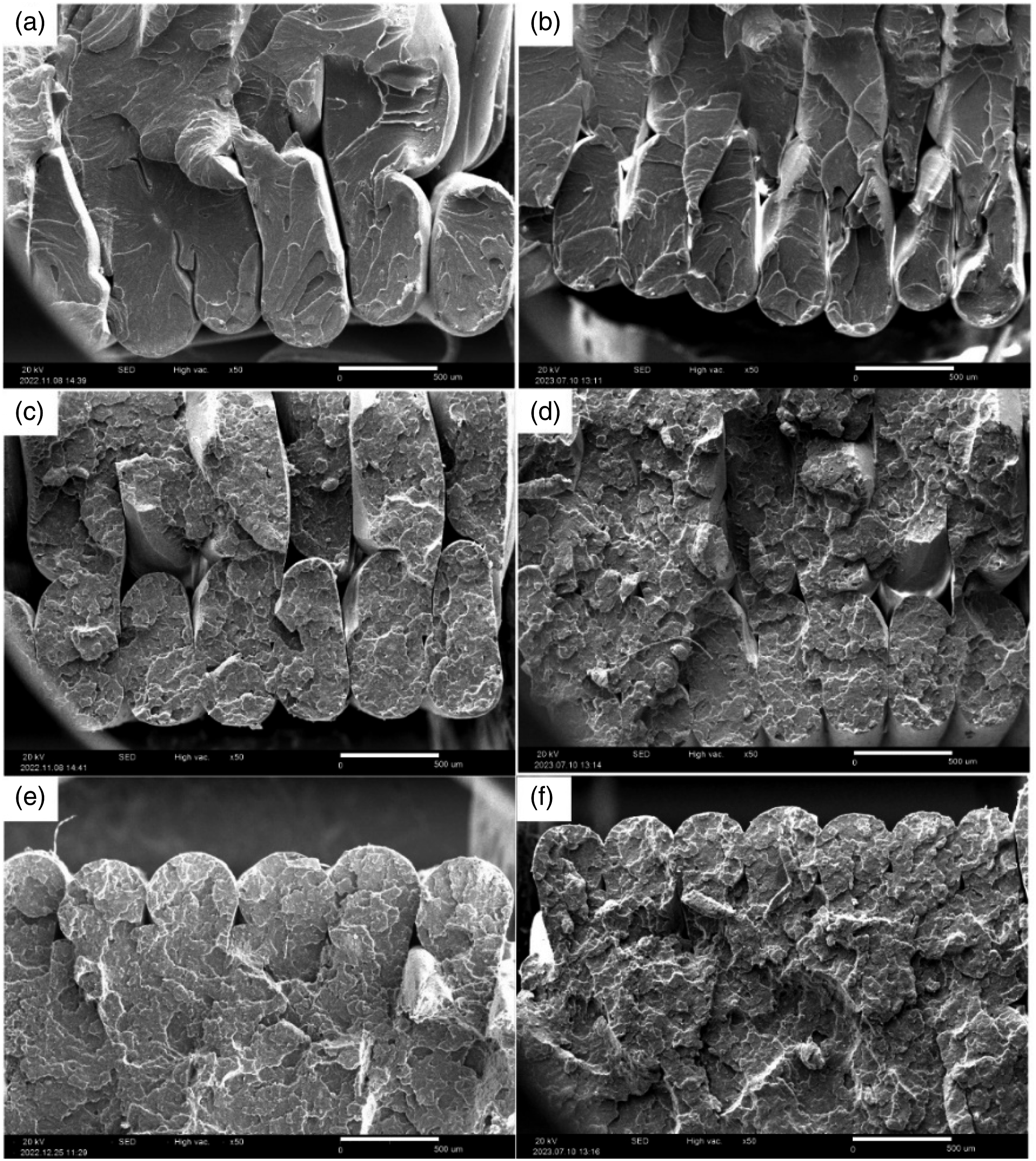
CNTs are abrasive materials that can cause some minor machining or wear on equipment. Figure 7 shows the nozzle diameters before and after printing the specimens. As illustrated, the nozzle internal diameter was increased by approximately 5%. The increase in nozzle diameter can lead to a decrease in 3D printing accuracy. Thus, it is suggested to use nozzles made from harder materials, such as silicon carbide.
43
SEM pictures of the nozzle ((a) before and ((b) after 3D printing.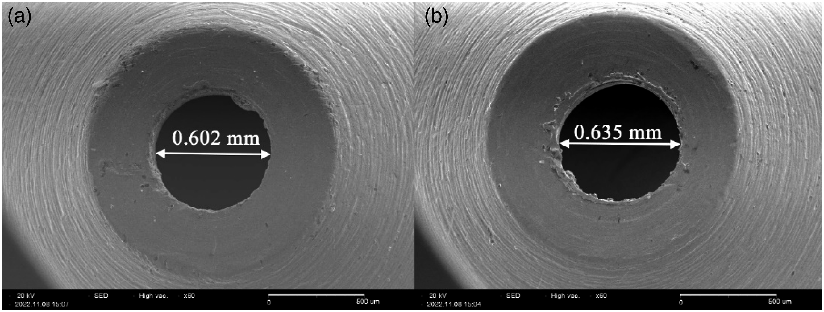
MFR test
Figure 8 shows the MFR test results. With an increase in CNT up to 6 wt%, the MFR decreased by 45% and reached a value of 17.67 g/10 min. In FDM, the flow behaviour of molten polymer through the nozzle affects 3D printing. A higher MFR causes less clogging at the nozzle. The quality of the printed part is negatively affected by high MFR. For low-viscosity molten polymers, it is difficult to control the shape of deposited filaments. Higher temperatures, larger nozzle diameters, and slower printing speeds are recommended when printing high-filled polymers. results of the MFR test.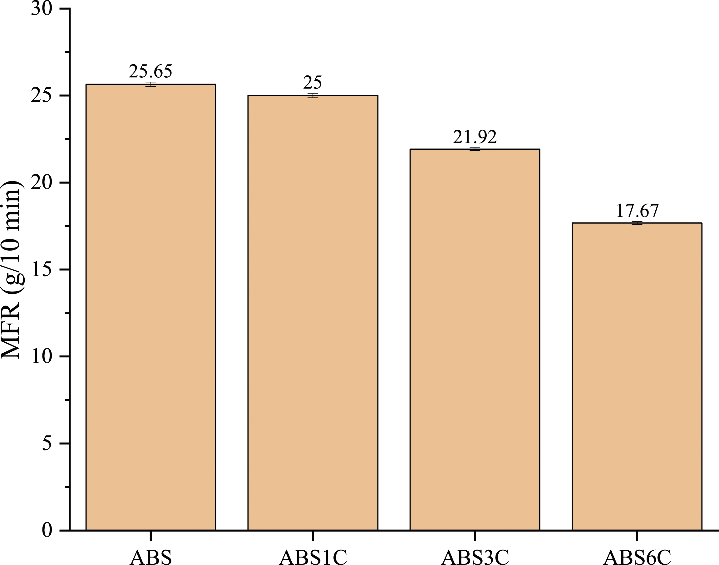
DMA test
Figure 9(a) and (b) show storage modulus and damping factor (tan δ). With the increase in CNT content up to 3 wt%, the storage modulus was increased. The highest modulus was found in the specimen ABS3C, in agreement with the tensile modulus obtained from the tensile test (Figure 5(b)). The tan δ indicates the ratio of energy dissipated to stored. The viscoelastic nature of ABS results in higher damping than other specimens, as can be seen in Figure 9(b). With the increase in CNT content, damping factors decreased. The peak of tan δ represents the glass transition temperature (Tg) for a specimen. With an increase in CNT up to 3 wt%, the Tg was increased from 113°C to 118°C and then reduced for ABS6C. (a) storage modulus and (b) damping factor obtained from the DMA test.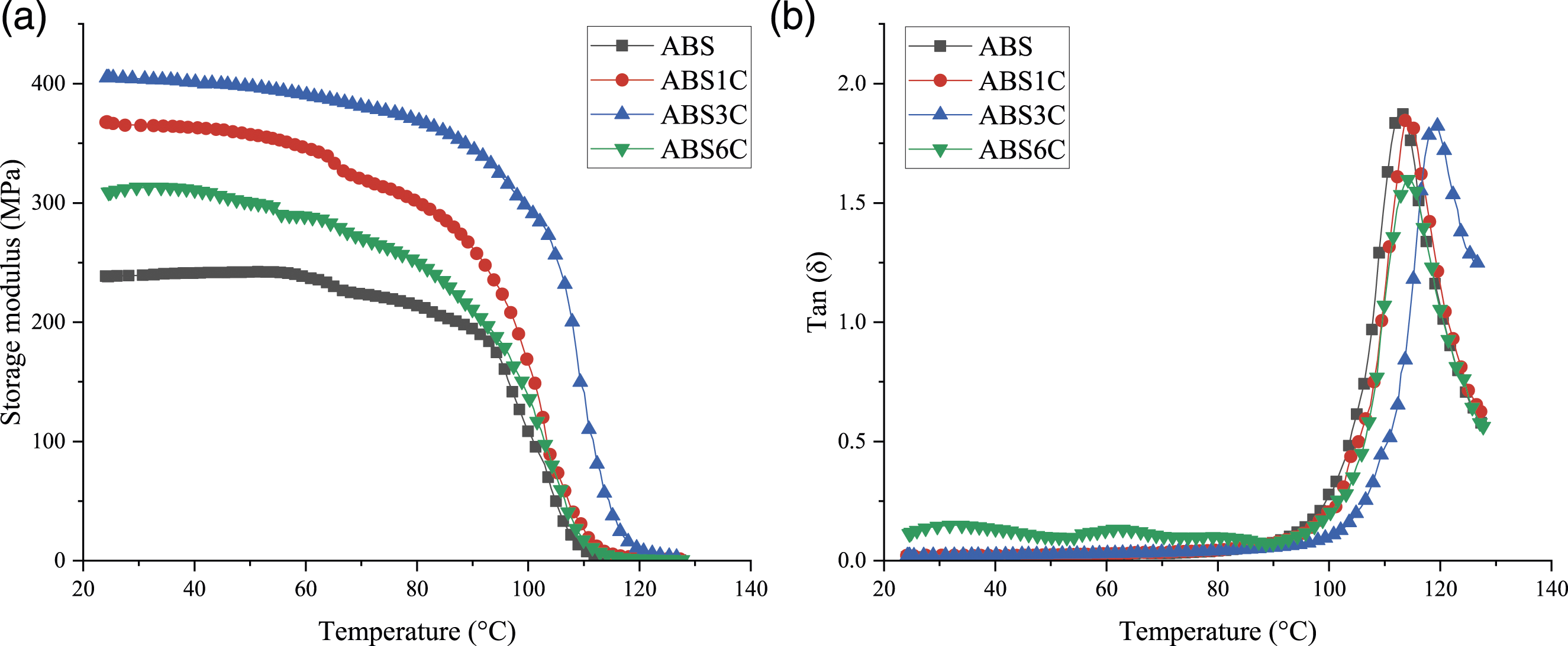
Conclusions
ABS/CNT composites were manufactured by FDM as an additive manufacturing method. The goal of this research was to expand the knowledge of properties to prepare them for several sectors. Composite filaments were produced with different CNT content. Results demonstrated that by adding CNT to pure ABS, mechanical, electrical, and electromagnetic shielding could be improved. In 3D printing, CNT affects MFRs and limits the amount of content that can be incorporated without causing problems. Due to the abrasive nature of CNT, precautions must be taken about the material type of nozzle. 3D-printed composites have the potential to be used in communication applications due to their relatively high EMI shielding and structural properties. With the inclusion of conductive particles in the polymer matrix, microwave heat treatment can enhance mechanical and electrical properties.
Footnotes
Acknowledgements
The authors acknowledge the funding support of Babol Noshirvani University of Technology through Grant program No. BNUT/391012/1399.
Declaration of conflicting interests
The author(s) declared no potential conflicts of interest with respect to the research, authorship, and/or publication of this article.
Funding
The author(s) disclosed receipt of the following financial support for the research, authorship, and/or publication of this article: This study is supported by Babol Noshirvani University of Technology (BNUT/391012/1399).