
Abstract
An orthogonal mixture woven composites with aramid yarns and carbon yarns are investigated in this work. A dual-scale computational homogenization algorithm is also proposed to address the cross-scale numerical problems. Models and methods for mesoscale and macroscale are illustrated separately. Two types of meso-structures are selected for comparison, which are termed as representative unit cell (RUC) and equivalent cross-ply laminate (ECPL), and the corresponding macro-structures are referred to as RUCs and equivalent cross-ply laminate plain-woven composites (ECPL-PWC). The key finds clarified that the ECPL-PWC takes more computational expenses compared with the RUCs, but the RUCs is in acceptable agreement with testing results, as well as the evaluation results of the ECPL-PWC would obtain very satisfactory accuracy through minor numerical adjustments. The final finite element damage results reveals that the RUCs is more accurate for local damage assessment, while the ECPL-PWC is better for global damage analysis.
Keywords
Introduction
Multiscale problems1,2 have received extensive attention in a variety of disciplines, incorporating structural chemistry, molecular biology, astrophysics, and the mechanics of composite materials et al. Multiscale methods can be divided into different genuses in their respective subject areas. All of the classifications have a strictly limited scope of scale, and there are complete theoretical models and methods within a single scale to describe the physical and chemical laws of researching objects. However, the methods and principles within a certain scale are generally not applicable to other scales, e. g. the principles of classical physics are not applicable to relativity and quantum physics. Therefore, the study of cross-scale methods has become a hot issue in various disciplines.
In structural mechanics of fiber-woven composites,
3
the homogenization method is the bridge of the cross-scale problem. The refinement problem in the lower scale is usually simplified by a suitable uniform approximation method with the upper scale. The homogenization method is an approximation method in cross-scale problem, which simplifies the calculation expense under the premise of satisfying a reasonable accuracy, so that the microscopic problems can be perfectly presented on the macroscopic level. Although there is a lack of acceptable accuracy, the homogenization method enables the representation of microscopic structural properties (micro-deformation, local fracture, etc.) on a macroscopic scale. In woven architectures, structural problems are usually classified into three scales, namely, microscale, mesoscale and macroscale (Figure 1). Mesoscale is the upper scale of the microscale (lower scale in reverse), and macroscale is also the upper scale of the mesoscale (lower scale in reverse).
4
Each single yarns are the targets in microscale, which are usually distributed in resin matrix with tow or random form. Representative homogenization methods of this scale incorporate Eshelby’s theory,5,6 Mori-Tanaka (M-T) method,7–11 Reuss model (equivalent compliance tensor)
12
and Voigt
13
model (equivalent stiffness tensor). Computational composite models often employ representative volume element (RVE) to characterize the unit structure in microscale.
14
However, a mesoscale model15–18 is usually the smallest weaving unit capable in representing the macroscopic scale. The architectures including orthogonal weaving,19–21 twill weaving,
22
and net weaving,
23
et al. It also contains information of lower scale, such as yarn type, size, profile, and weaving path (Figure 2). Computational architectures of mesoscale are usually characterized by representative unit cell (RUC).24,25 Finally, the macroscale model is presented in the form of woven fabrics with various woven forms. In mathematical model, it can be realized by the periodic superposition of infinite RUCs in mesoscale, and with the help of computational homogenization,26,27 the boundary conditions such as loading, stress, displacement, etc. in mesoscale can be effectively transferred into the macroscale. Nevertheless, it is regrettable that this simple superposition is confirmed numerically tedious and expensive. Therefore, the popular equivalent cross-ply laminate (ECPL) cell28–30 is currently employed by researchers for mesoscale to macroscale homogenization. Because ECPL removes profile information of yarns, such as the curvature, weaving path, and cross-section of the yarn in RUC, and adopts a specific homogenization method, the numerical model can be greatly simplified, thereby deeply reducing the computing time and modeling cost of macroscopic composite architectures. For example, Ref.
28
describes the damage initiation and evolution of the mesoscale model with low-velocity impact31,32 loading conditions of plain weave composite models characterized by ECPL. The work of Mulay and Udhayaraman29,30 studied the mesoscale failure modes of plain weave textile composite (PWTC) in mesoscale with the ECPL, and generalized the M-T failure theory into ECPL. In addition, Hou et al.
33
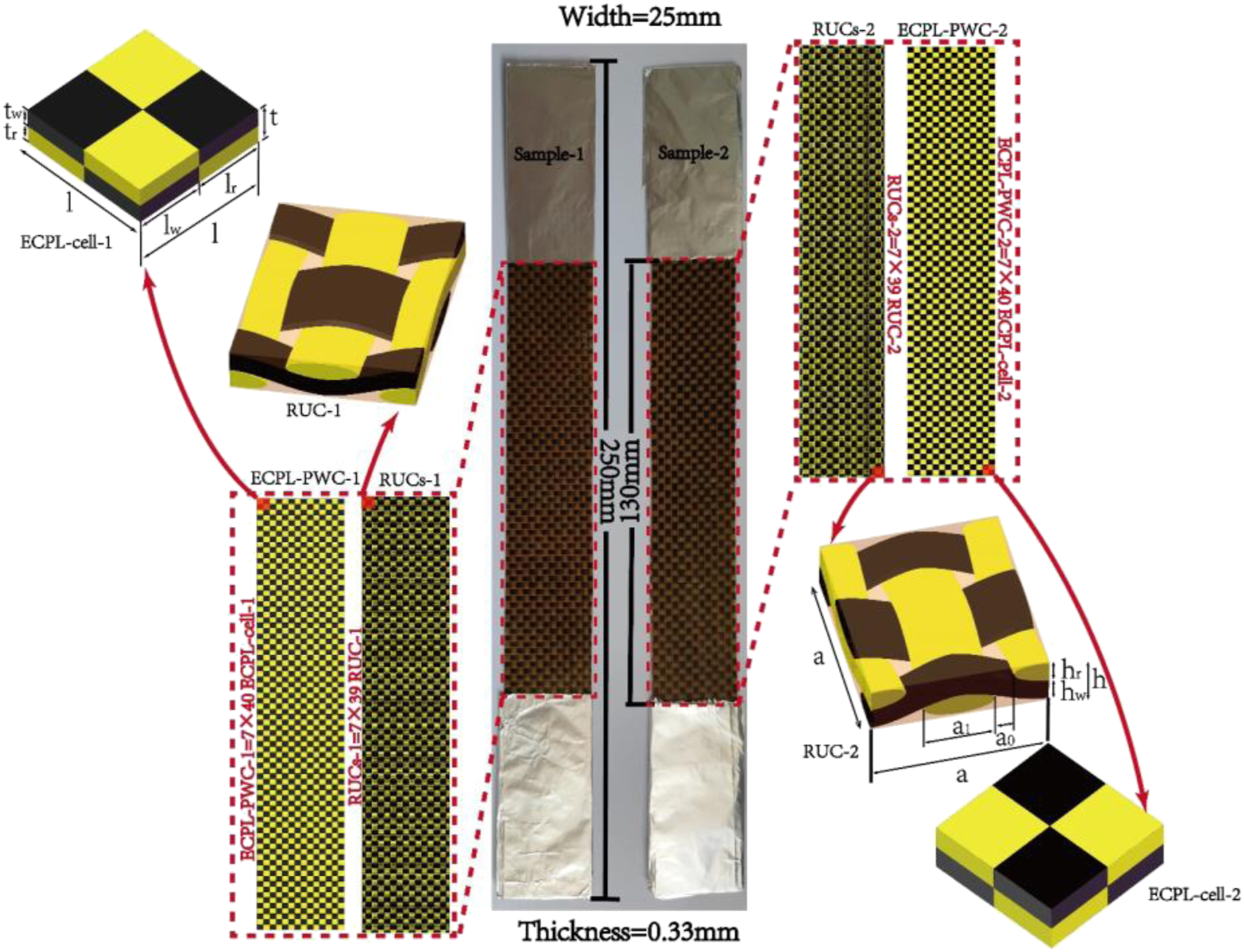
adopted ECPL combined with the classical laminate theory and M-T theory, the progressive damage failure of adhesive laminate is studied. It is found that the application of the ECPL cell reduces the computation time and cost by 95% according to their projection. Multiscale structures of 2D orthogonal woven composites with mixture yarns. Numerical models and dimensions of testing samples.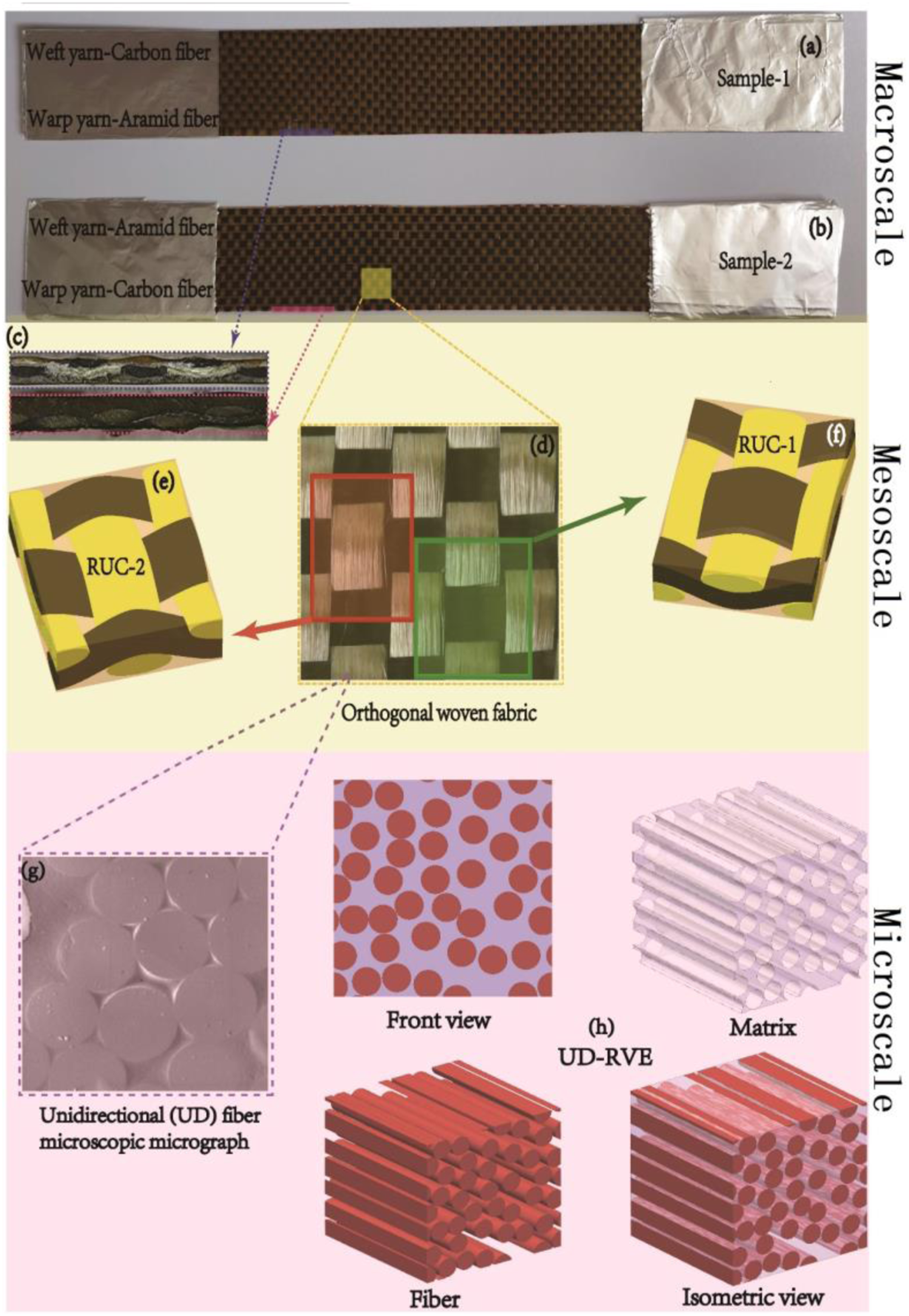
Orthogonal woven structures can be classified into 2D, 34 2.5D,35–37 and 3D38–42 genus. There are discrepancies in weaving configurations among them. 2D orthogonal woven, however, also known as plain orthogonal woven. The 2D structure is an architecture in which a single layer of warp yarns plus a single layer of weft yarns are intertwined with each other, while the 2.5D is a woven structure composed of multiple layers of warp yarns arranged in parallel with all weft yarns maintain a consistent weaving path. Whereas, 3D structure is the architecture formed by the arrangement of multiple warp yarns and multiple weft yarns following various mixed weaving paths. Due to the complexity and diversity of 2.5D and 3D genus, the cost of numerical modeling and computation is currently expensive. Therefore, 2D orthogonal plain-woven composites (PWC) with relatively simple configurations are still a research hotspot in mesoscale. Muhammad et al. 43 adopted the deep convolutional neural networks (DCNN) method for cutting computerized tomography (CT) images44,45 of woven composite structures and achieved 96% accuracy. Wang et al. 46 explored the indeterminacy of twisting deformation of orthogonal woven structures under external force. Cao et al. 47 employed both experimental and mesoscale numerical methods to predict the progressive damage failure behavior 48 of orthogonal woven under tensile and compressive loading conditions.
Regrettably, the current research mainly focuses on the 2D orthogonal PWC with one type of fiber, or mixed layup with different fiber cloths.49,50 However, the mixed braiding of different types is rarely in attention, and some of them 51 is mainly concentrated on mechanical experimental research without relevant multi-scale numerical methods. To achieve these ends, this work deals with the 2D orthogonal hybrid woven structure of carbon fiber and aramid fiber, and discusses the analysis results of two homogenization models, RUC and ECPL, respectively. This work is carried out between mesoscale and macroscale, without considering the effects of the microscale. We proposed a dual-scale computational homogenization (DSCH) nested incremental iterative algorithm to deal with the geometric and mechanical relations of these two scales. Therefore, the upper and lower scales described below refer to the macroscale and the mesoscale, by default.
Multiscale problems of plain-woven composite
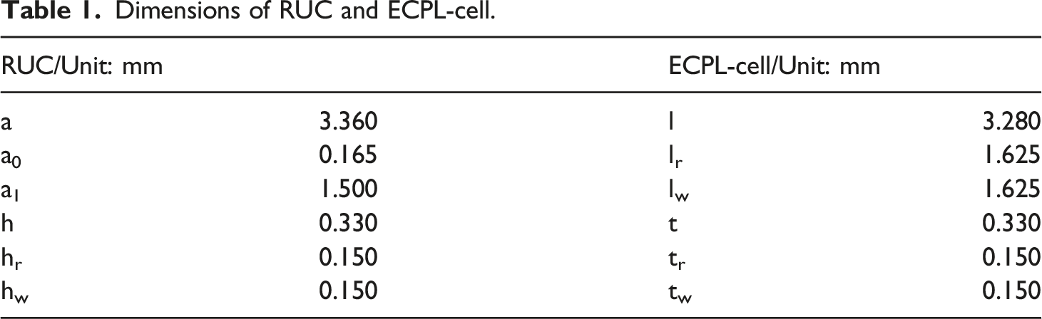
The multi-scale models of PWC are described in Figure 1. Mechanical testing samples in macroscale (Figure 1(a) and (b)) are PWC formed by orthogonal knitting of carbon (black) and aramid (yellow) yarn. For the purpose of strengthening the weaving of the fiber cloth, as well as the experimental samples can be cut and shaped. Before cutting the fiber cloth, epoxy resin is employed for prepreg of woven. In order to study the orthogonality anisotropy of the mechanical properties in orthogonal heterogeneous yarns of woven, the experimental samples are divided into sample-1 (Figure 1(a)), whose warps are aramid yarn, wefts are carbon yarn, and sample-2 (Figure 1(b)), whose warps are carbon yarn, and wefts are aramid yarn. The sizes of samples are depicted in Figure 3 Nevertheless, mesoscale (Figure 1(c)–(f)) is the lower scale of macroscale, which considers the structures of the woven, incorporating weaving structure, cross-section morphology, and local structure. Figure 1(c) shows the cross-section morphology of the experimental samples in mesoscale. RUC-1 (Figure 1(f)) and RUC-2 (Figure 1(e)) are selected respectively to characterize the minimum braiding units of Specimen-1 and Specimen-2 respectively. The dimensions of RUCs are labelled on Figure 3 and illustrated in Table 1. Similarly, microscale (Figure 1(g) and (h)) is the lower scale of mesoscale, which depicts the interaction between a single fiber with other fibers and matrix. In numerical methods, RVE is usually adopted to characterize the micro performance in microscale. Figure 1(g) shows the sectional micro morphology of fiber filament in woven structure, and Figure 1(h) is the structural characteristics of the fiber filament in the micro level with UD-RVE,
32
which including the diameter, length, distribution, twist, matrix/fiber interface, percentage and other details of microstructure. In this work, microscale is not considered, and we only discuss the DSCH from mesoscale to macroscale. Structure of multiscale numerical models. Dimensions of RUC and ECPL-cell.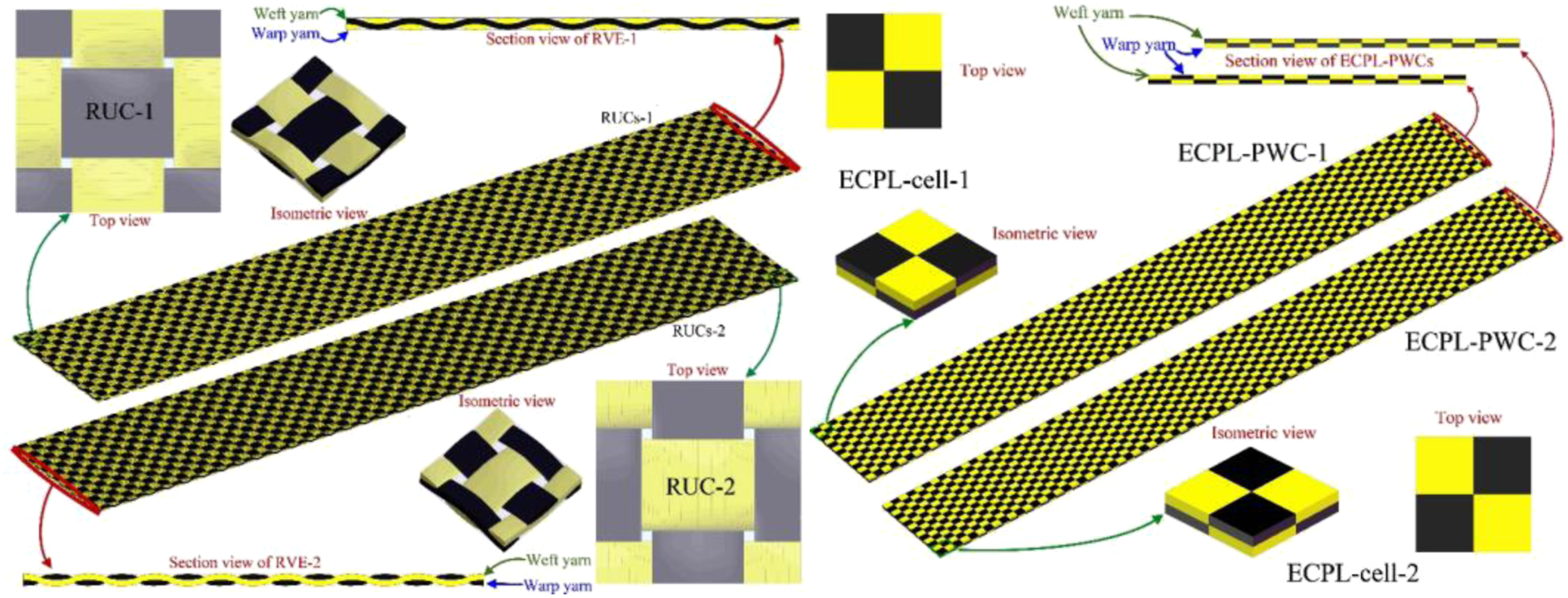
Experimental samples and their multi-scale characterization
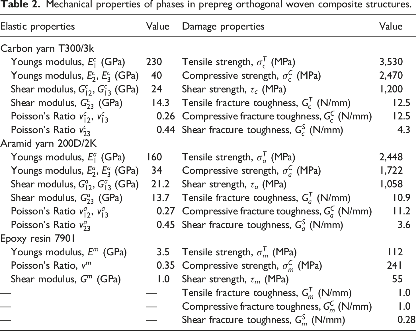
Mechanical properties of phases in prepreg orthogonal woven composite structures.
For the purpose of facilitating multiscale numerical method of tensile specimens, RUC and ECPL-cell are respective selected as the minimum periodic unit in macroscale (Figure 2). However, ECPL-cell can be viewed as a simplified structure of RUC proposed in Ref.,28–30,33 which will greatly reduce the homogenization calculation from mesoscale to macroscale with the premise of ensuring adequate calculation accuracy. The sizes of these two structures are inconsistent, the specific sizes and corresponding values are depicted in Figure 3 and Table 1. Furthermore, a simplified numerical structure of the tensile specimen is adopted for reducing the calculation expense, we only considered the length of testing area with 130 mm, and ignored the length of the clamping area. Respective meso-structures RUC and ECPL-cell are selected for manifesting Sample-1 and Sample-2. RUC-1 and ECPL-cell-1 are employed to characterize Sample-1with periodical layout, as well as RUC-2 and ECPL-cell-2 for Sample-2 as shown in Figures 2 and 3. The yarns coloring in RUC and ECPL-cell is consistent with experimental samples for identification, that is the black areas are carbon yarns and yellow ones are aramid yarns. The testing area of macroscale shown in Figure 3 is divided into four types, two of them are composed of RUCs in periodic layout named RUCs-1, and RUCs-2, and the others are periodically made up of ECPL cells called ECPL-PWC-1 and ECPL-PWC-2. Finally, the geometrical morphology of macroscale structures in testing area are generated by periodic superposition with 7 × 39 RUCs and 7 × 40 ECPL-cells, respectively (Figure 3).
Mesoscale-macroscale computational homogenization
A significant factor in modeling of multiscale structures is selecting the most appropriate scale with regards to the problem for investigation. The modeling approach discussed in this work is from mesoscale to macroscale, which is also confined to an important restriction, that is the characteristic size of lower scale must be several orders of magnitude smaller than the characteristic size of upper scale, or in other terms, the characteristic length of heterogeneities model (mesoscale) should be much smaller than characteristic size of the homogeneous model (macroscale).
Besides, a characteristic volume of the studied heterogeneities medium should be sufficiently large to be representative of the microstructure, at meantime, however, it also should also be viewed as a computational homogeneous material point of its upper scale (Figure 4(a)). This notion leads to define a RUC or ECPL cell in mesoscale. Such consideration is very essential in applying an appropriate modeling strategy. In this paper, bold-type letter and the voigt notes
52
are employed to represent the tensor formulas of homogenization theory. Dual-scale domain and damage criterion (a) homogeneous macroscale Ω with heterogeneous mesoscale domains 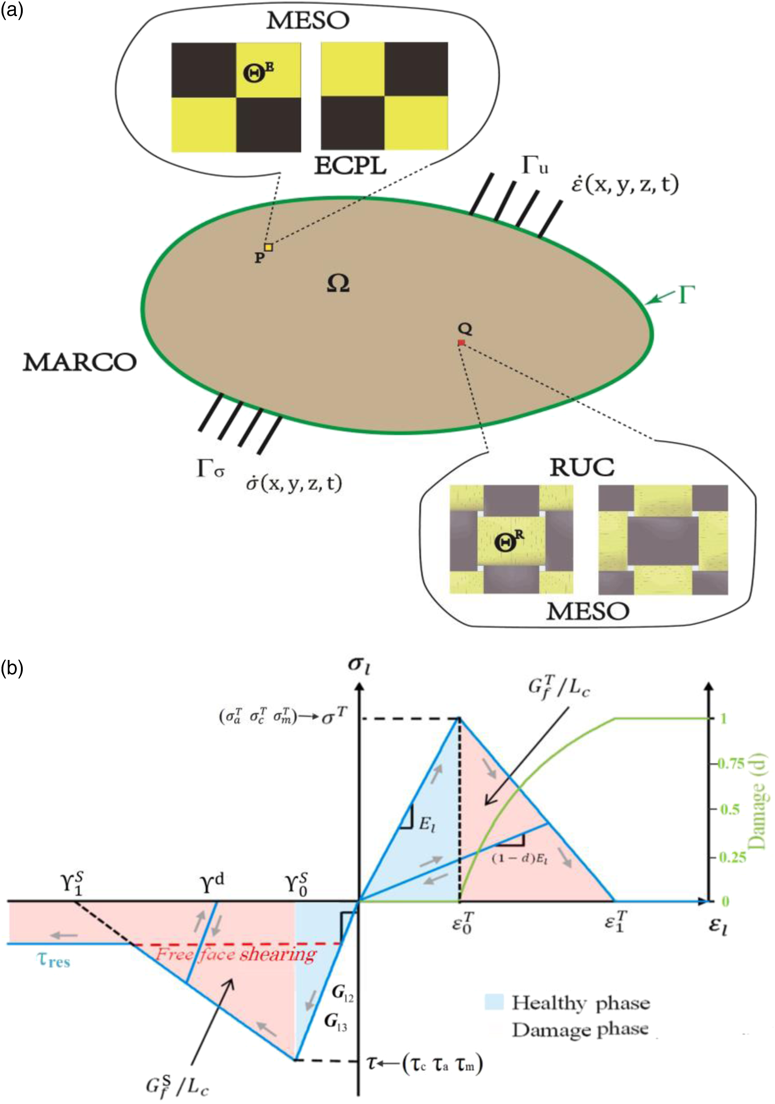
A DSCH based on nested parallel processors is worked on orthogonal mixture woven macro-structure with periodic meso-structures. In mesoscale, both RUC and ECPL with periodic boundary conditions are considered as macroscale integration points Q and P, respectively (Figure 4(a)). The macro spatial domain Ω with mesoscale spatial domains, which
Fibers’ breakage is considered using a failure criterion formulated within ultimate strength as shown in Figure 4(b).
where
In tension, failure is classically driven by a damage parameter, allowing the dissipation of the fracture energy of tensile corresponding to fiber failure (
In addition, once the fracture energy is dissipated in shear, a constant shear resistant stress
With respect to longitudinal or transverse directions, when the failure strain in tension (
Macroscale problem
Domain 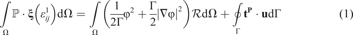
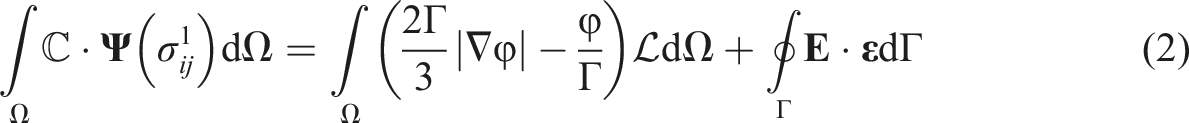
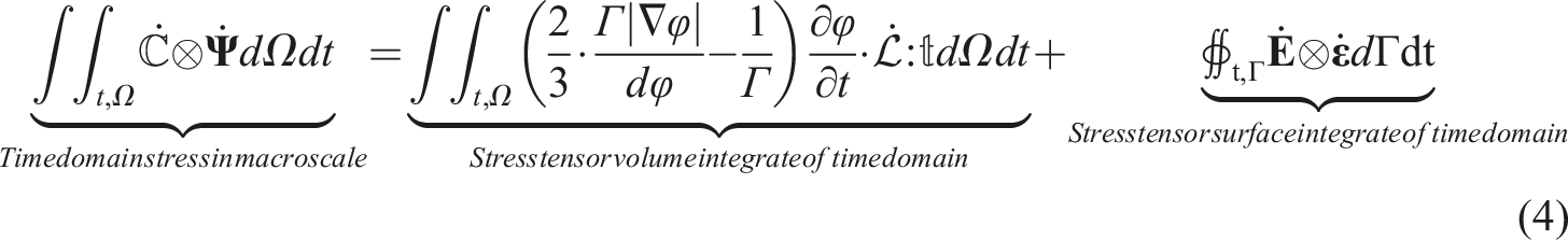
In the natural iterative process, the macro field quantity changes along time domain, therefore the transient macro homogenization governing equation (Equations (1) and (2)) is the rule of numerical method within a single time step. Meanwhile, the temporal aggregation of the second order tensor is a fourth order tensor. In this work, the temporal dependence tensors are marked with the symbol “.” on top by default, in this way, the fourth order displacement tensor 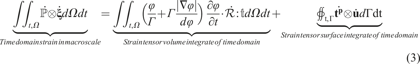
Mesoscale problem
Orthogonal woven consist of textile, which is a reticulation of interlocked fibers prepreg in a matrix. The fiber tows running along the length of textiles are referred to as warps (warp yarns), while running perpendicular to the length are called wefts (weft yarns) or fills.
Mesoscale is the lower scale of the macroscale, and it can be viewed an integral point of macroscale (Figure 4). The integral point should fully represent the structural characteristics of macroscale. In macroscale, two types of mesoscale points, RUC and ECPL with respective spatial domain
Mesoscale problem considers the structural characteristics of the cells (ECPL and RUC). In mesoscale, the structural stiffness can be expressed by the modulus of matrix, wefts and warps, as well as respective volume fractions.
The compliance tensor ℒ (inverse of elasticity tensor ℛ) of a mesoscale orthotropic structure can be expressed in terms of the three Youngs moduli E11, E22, E33, the three shear moduli G12, G13, G23, and the three Poisson ratios ν12, ν31, ν23 in following form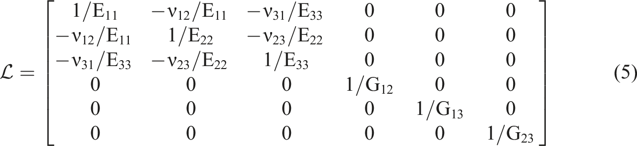
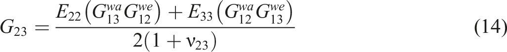
The components of mesoscale modulus and Poisson’s ratio can be depicted by equations 6–14. where V
f
is volume fraction, the superscript “we” denotes wefts, and “wa” is warps. Since the resin matrix is isotropic, a single note “m” is used for the properties of matrix.


As well as RUC-2, afterwards, the volume fraction of each phase only needs to change the superscript “wa” to “we” from equations 15–17 on account of orthogonal symmetry.
In ECPL-1, the expression of volume fractions are simpler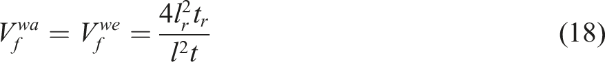


Equations (20) and (21) can also be written as the following transient form

Label Θ refers to one of the domains 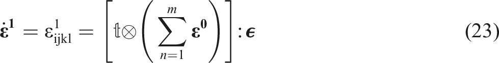
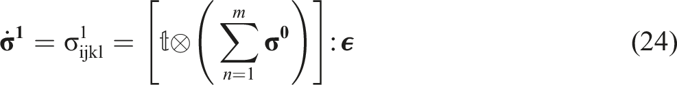
Superscript m is the total number of integral points of the units replaced by RUC or ECPL in macroscale. According to Figure 3, there are 7 × 40 ECPLs and 7 × 39 RUCs obviously appear in macrostructures. ϵ is the third-order Cartesian permutation tensor defined as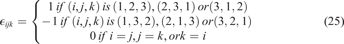
Iteration algorithm between mesoscale and macroscale
The iteration algorithm of the presented computational homogenization framework is following performed by a nested parallel processors iteration scheme between the coupled dual-scale numerical analysis.
The macroscopic structure to be analyzed is discretized by finite elements. To each macroscopic integration point, a unique meso-cell RUC/ECPL is assigned. Remind that, it suffices to make this scale exchange when those zones are highly non-linear or evolving in general, such as closed-form constitutive equations become clearly inaccurate. In order to initiate the macroscopic finite element analysis, surface integrate on every integration point are required. To obtain these integrates from the meso-structural properties, a preparing mesoscopic analysis is performed. During initialization stiffness matrix, an undeformed RUC/ECPL is assembled and used to derive the initial macroscopic constitutive equation at a macroscopic integration domain.
Dual-scale computational homogenization nested incremental iterative solution scheme.
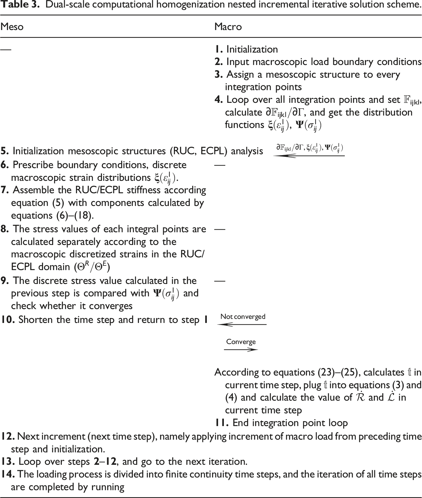
Clearly, the DSCH algorithm described above is parallel by the nature. All mesoscopic (RUC/ECPL) calculations for one step macroscopic iteration can be performed in parallel without any exchange of data between them. Therefore, the employment of parallel processors for the homogenization method significantly reduces the total meso to macro computing time.
Results and discussion
Primarily, multiple continuous tensile tests are carried out on test sample-1 and sample-2 respectively, the error band distribution functions of the two samples are also obtained. Meanwhile, three sets of experimental data are randomly selected to compare and analyze the robustness with disparate numerical results. And the images of local in situ damage under dynamic stretching at various time points are obtained. Subsequently, the role of CPU hyperthreading and the operation cores on computationally capacity in numerical analysis is compared. Finally, it reveals the FEA results of computational homogenization in macro and mesoscales, respectively.
Comparison of computational homogenization strategy with experimental results
30 times tensile tests are carried out on separate woven structures of Sample-1 and Sample-2 with a loading rate of 1 mm/min respectively. The distribution of the tensile test error bands of the two samples are obtained, and three representative tensile curves are randomly selected for comparing. In loading procedure, five different timing points, ①, ②, ③, ④ and ⑤ are selected according to the sequence of loading displacement (Figure 5). An in-situ photography microscope is employed for shooting in-situ damage microscopic photography at different positions on the tensile sample corresponding to these timing points (Figure 6). Moreover, three typical methods are considered, which are direct finite element method, calculation homogenization based on RUC and ECPL model. Comparison of load-displacement curves between experimental results and various numerical analysis in uniaxial tensile tests. (a) Sample-1, (b) Sample-2. Local in situ morphology of two samples in different time points. (a) Sample-1, (b) Sample-2.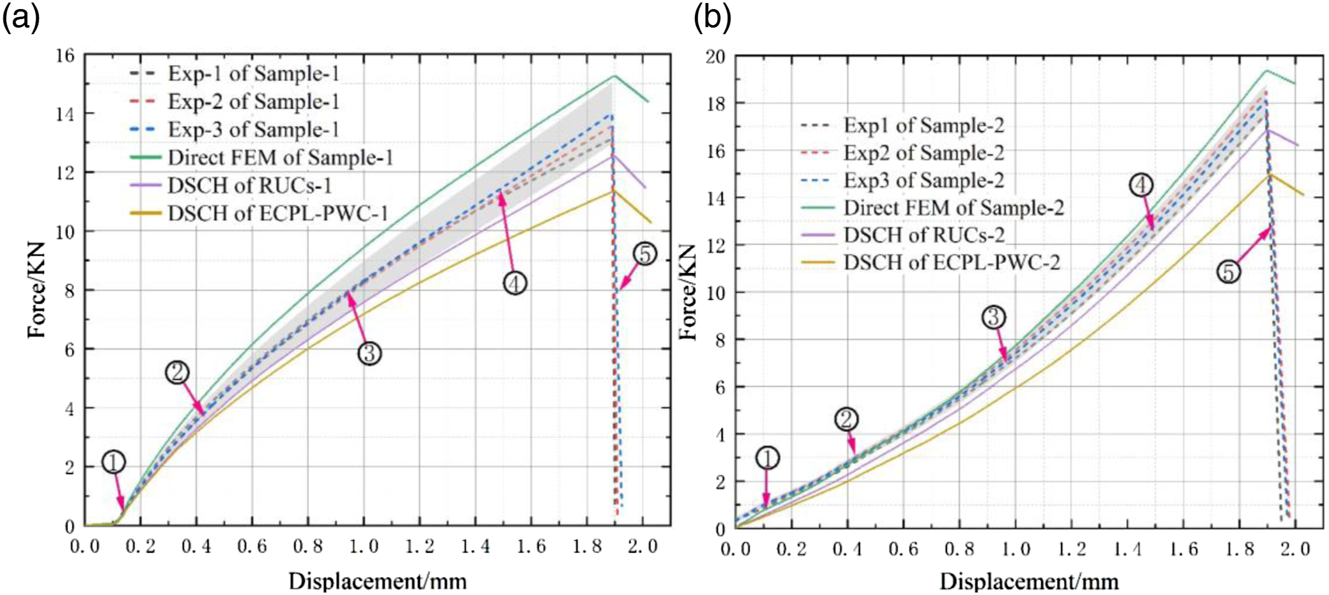
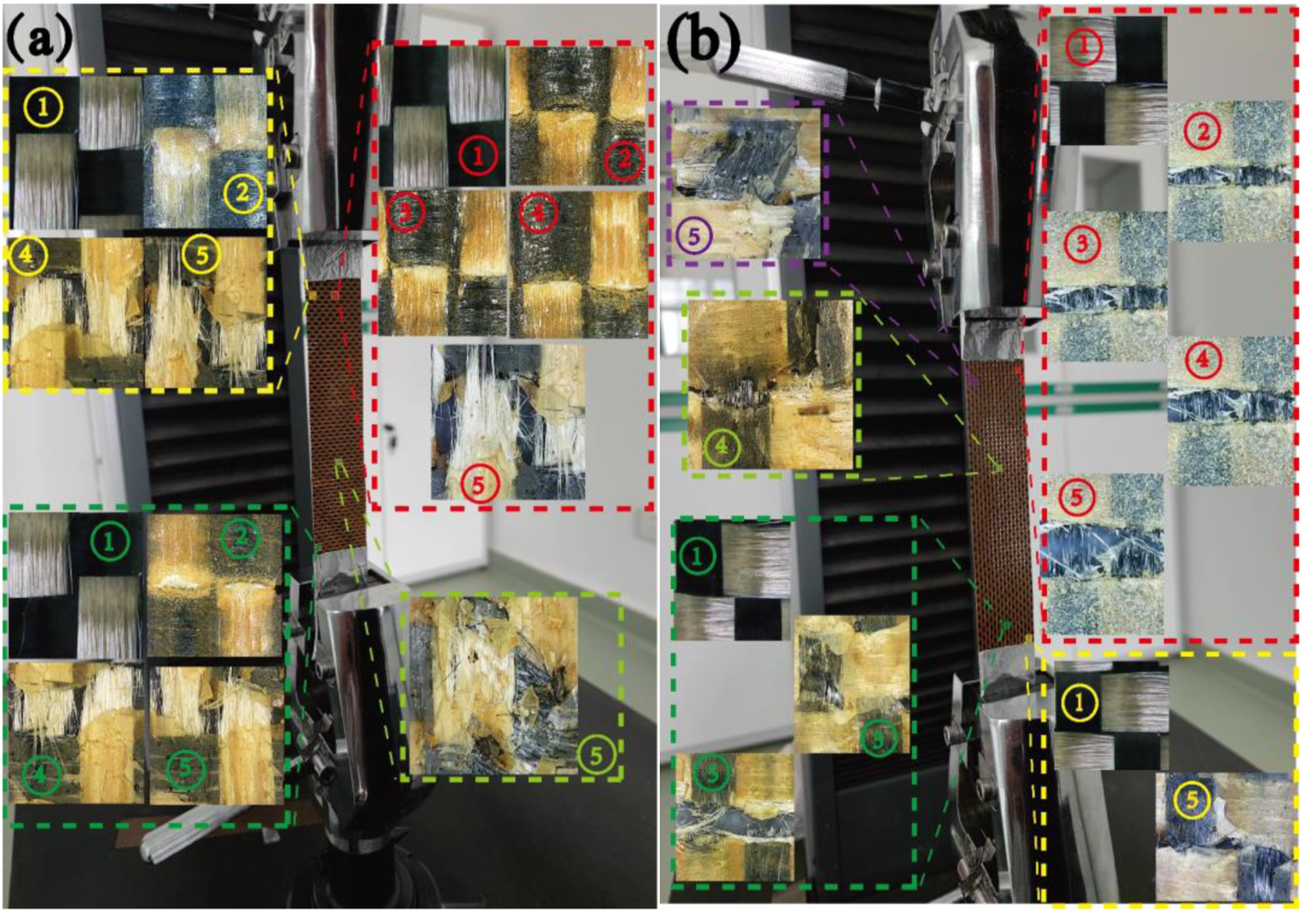
Figure 5(a) and (b) are the comparisons of the experimental and numerical results of sample-1 and -2. The average tensile force and maximum displacement of sample-1 are 17.47 KN and 1.895 mm, while the values of sample 2 are 13.13 KN and 1.889 mm. The tensile force of testing is parallel to the direction of the warp yarn, so the warps bear the normal stress principally, while the wefts mainly suffer the shear stress from tighten of warps. As shown in Figure 3, the warps of sample-1 are aramid yarns and the wefts are carbon yarns, On the contrary, the warps of sample-2 are carbon yarns, and the wefts are aramid yarns. Therefore, the tensile force of the sample mainly depends on the strength of the warps, the testing results are consistent with the anisotropy woven structure.
Secondly, as shown from the statistics distribution of error bands, it depicted a trend from narrowing to widening throughout the loading procedural in both two samples. The error band of sample-1 is slightly broader than sample-2, which disclose that the stability of tensile force of aramid yarn is not as good as carbon yarn. The agreement between the experimental and numerical load-displacement curves is relatively stable, and showing similar variation trends among them. However, the numerical results are deviate from the experimental error band. In this regard, the results of the direct finite element method are larger than experimental error band, while the two groups of homogenized results are both smaller than the error band. The prediction results of direct finite element method (FEM) and DSCH of RUCs are in good agreement with the experimental results, while the result of DSCH of ECPL-PWC is not precise enough at terminal of the curve, but the terminal tendency of the DSCH of ECPL-PWC method is consistent with the experimental results. And it is the most economical method for computing resources, which will be verified in the coming section. One can make corresponding corrections to the simulation results of DSCH of ECPL-PWC, so as to achieve satisfactory prediction accuracy of terminal.
In addition, five different points are selected on the load-displacement curve in Figure 5, and adopted in-situ shooting method to record the local damage of the sample at these five time points, which are also shown in Figure 6. The result shows that the final failure of the hybrid woven specimens is all dominated by the localized fracture of the warp yarns. As depicted in the micrographs of time-series damage evolution, the initial failure occurs in superficial resin matrix fracture. Through observation, this process has already occurred in steps ①–③, and the fracture of the yarns usually appears in the sequence of steps ③–⑤. Comparing the matrix failure process shown in the red dotted line box of sample-1 (Figure 6(a)) and sample-2 (Figure 6(b)), the resin in sample-1 appears brittle cracks (the matrix fractures with fragments), while the resin in sample-2 is viscoplastic cracks (the matrix failure surface appears rough and not smooth). This reveals that the weft yarns (aramid) in sample-1 break instantaneously, while the weft yarns (carbon) in sample-2 break asymptotically. This speculation can be verified from the sequential variations from step ① to ⑤ depicted in the red dashed boxes in Figure 6(a) and (b). In Figure 6(a), the breakage of aramid yarns mainly occurs between ④ and ⑤, and since the high strength of yarns, the yarn fracture is not obvious in step ①–④. In Figure 6(b), the damage of the carbon yarns has already occurred in step ②, and it gradually grow in the process of ②–⑤.
The computing efficiency with various CPU configurations
The numerical calculation is carried out on workstation of Intel ® Xeon ® E5-2687W v3 processors (2 × 10 cores, 3.1–3.5 GHz) with RAM capacity of 256 GB. In the numerical analysis, the macro models (ECPL-PWC and RUCs) are divided into 7 × 40 and 7 × 39 meso-models (ECPL-cell and RUC) in Figure 3, and each meso-model appear periodic boundary condition. ECPL-cell and RUC are discrete by a uniform mesh with 953,568 and 929,734 elements separately. Although the element number of the two models are unequal (ECPL-cell is slightly larger than RUC) in mesoscale, the total number of discrete elements of the two types in macroscale (ECPL-PWC and RUCs) are nearly equal.
As illustrated in Figure 7, when a small number of cores (<6) are turned on, the numerical calculation is time-consuming. When the number of cores increases from 2 to 8, the elapsed time is significantly improved. When the number of cores exceeds 8, the temporal costing is improved un-conspicuously. In case the number of open cores reaches 12, the time consumption tends to be stable. In terms of computing efficiency, the temporal costing of DSCH with ECPL cells is 85% less than that of the DSCH with RUCs when the hyper threading function of CPU is turned off. After the Hyper Threading function is turned on, the proportion is increased to 95%. Comparing with black dotted line of Figure 7(a) and (b), however, the DSCH with RUCs improves the computing efficiency by 30% after the Hyper Threading enabled. It should be noted that the direct FEM is the result obtained by FE software for calculating macro model without implanting any homogenization method. In general, the efficiency of DSCH methods is obviously higher than direct FEM. The influence of multi-core parallel computing and hyper-threading on computing efficiency. (a) Hyper-threading OFF, (b) Hyper-threading ON.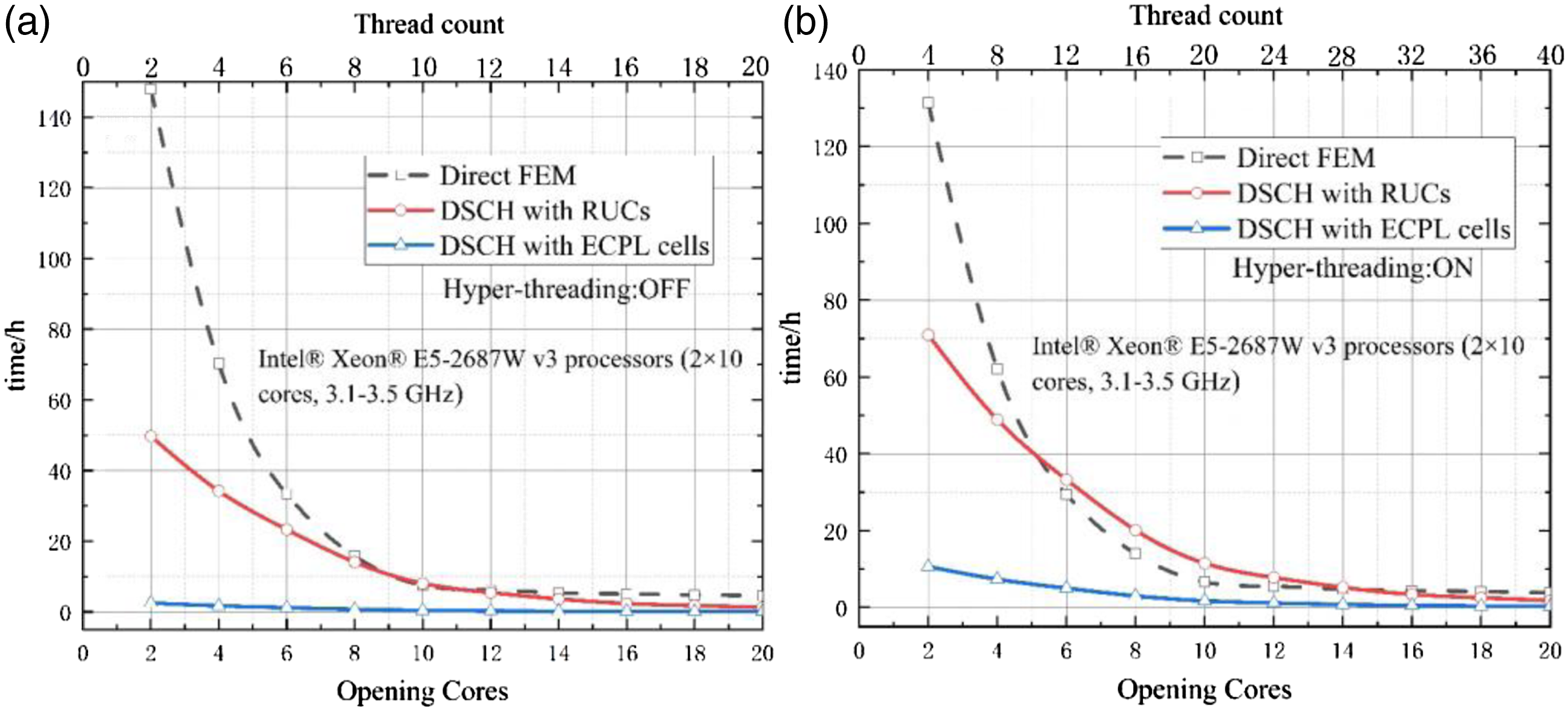
Figure 8 shows the relationship between the element numbers and the calculation efficiency with all 20 cores turned on. It depicted that the calculation efficiency of direct FEM is linear with the number of elements. While, the tendency in the computational homogenization algorithm is nonlinear. It is worth noting that, compared with Figure 8(a) and (b), after the hyper threading enabled, the computing efficiency of DSCH with RUCs is significantly improved, while the efficiency of the DSCH with ECPL cells is improved un-conspicuously. Besides the temporal costing of the direct FEM is increased 16%. Therefore, turning on hyper threading has obvious superiority for DSCH method, and has adverse effects on the direct finite element algorithm. The relationship between the computational efficiency of hyper-threading and the variation of element amounts in unit cells. (a) Hyper-threading: OFF, (b) Hyper-threading: ON.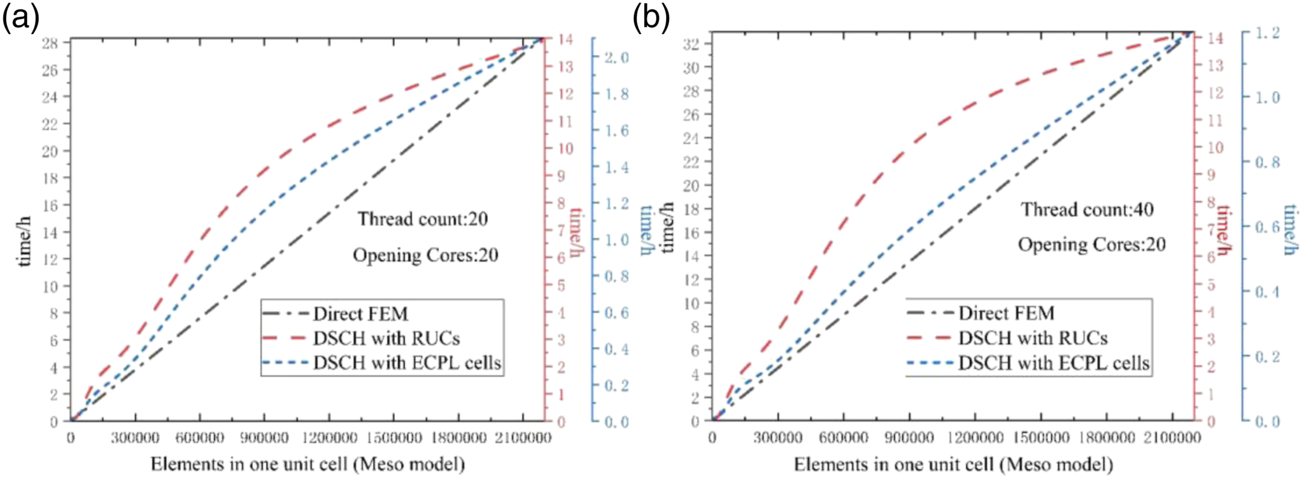
FEM results of dual-scale computational homogenization
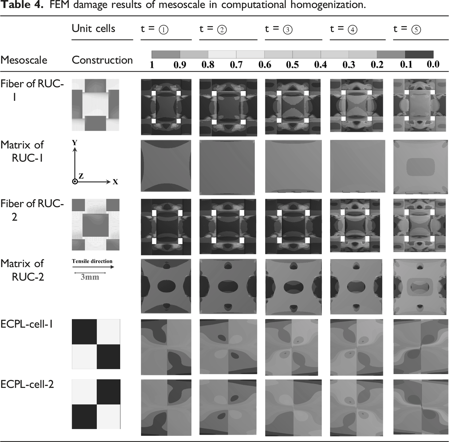
This section discusses the FEM and DSCH damage results of macroscale and mesoscale models respectively, and presents them in the form of finite element damage cloud chart. Because the homogenization is applied on the upper scale (macroscale), specifically, the direct finite element results of the lower scale are mapped to its upper scale with the strategy of computational homogenization. Therefore, the lower scale (mesoscale) contour plots (Here, the “contour” is the extent of damage from 0 to 1) in this section are directly yields by direct FEM, while the upper scale results are obtained according to algorithm of DSCH described above.
Direct finite element damage evolution of mesoscale models
Two forms of unit cell, RUC and ECPL are considered for the mesoscale structure, and they are divided into two types according to different weaving methods. See Figures 2 and 3 for details. It should be noted here that in the homogenization algorithm, the results of the mesoscale model are calculated directly, and the direct FEM result of mesoscale is served for the homogenization calculation of its upper scale.
FEM damage results of mesoscale in computational homogenization.

DSCH results of macro models
According to Figure 3, there are four types of macro-structures, which are upper scale models for DSCH. The damage distributions of macro-structures are obtained according to the DSCH. Figure 9 shows the damage results of step ⑤ in four macro-structures. Figure 9(a)–(d) are the front view of these four structures, and Figure 9(e) and (f) are the corresponding sectional view. FEM damage results of macroscale computational homogenization. (a) RUCs-1, (b) RUCs-2, (c) ECPL-PWC-1, (d) ECPL-PWC-2, (e) Cross section of RUCs-1, (f) Cross section of RUCs-2, (g) Cross section of ECPL-PWC-1, and (h) Cross section of ECPL-PWC-2.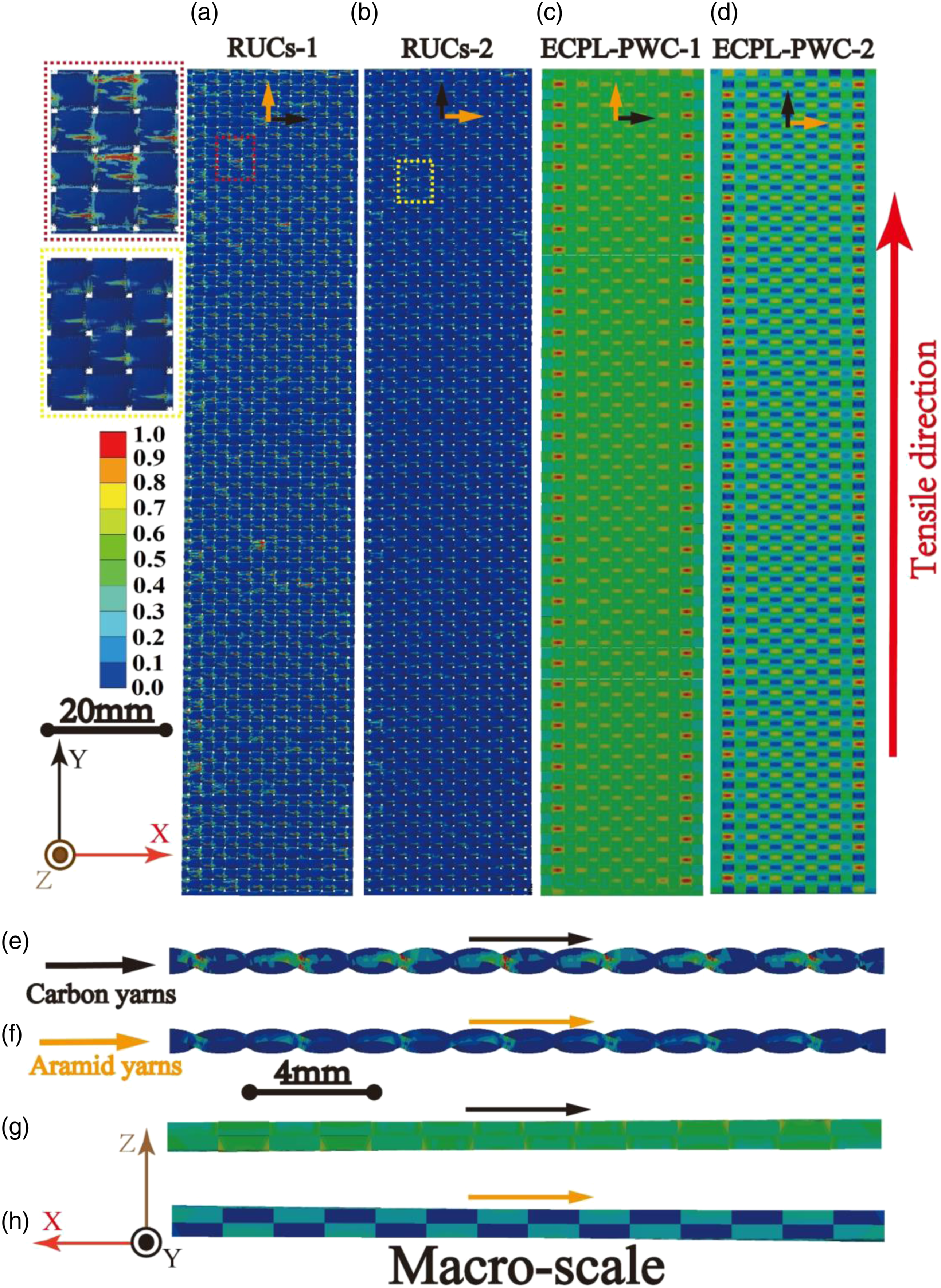
First of all, it can be seen that the contour plots in Figure 9 is inconsistent with its lower scale (Table 4), and there are disparate damage degrees on different locations of macro-structures. This is because the computational homogenization redistributes the stress results in the sub cells of upper scale, and makes the evaluation results are more consistent with the real testing. Secondly, the damage degree of RUCs-2/ECPL-PWC-2 is smaller than RUCs-1/ECPL-PWC-1, which is also depended on the tensile strength. Results shows that the strength of RUCs-2/ECPL-PWC-2 is larger than RUCs-1/ECPL-PWC-1, which is similar to the evaluation result in the mesoscale (Table 4). In addition, according to the local magnified pictures and sectional nephogram of the RUCs, the failure locations are concentrated in the positions that the woven yarns intertwined. Since the shear stress in these positions are the largest. So, warp yarns are subjected to both external tensile and shear forces of intertwined area with wefts. This implied that multiaxial load failure occurs first on warp yarns, while weft yarns only bear the shearing force from warp yarns and without external tensile forces, which is verified the result shows warp yarns primarily cracked and the weft yarns without obvious damage. Moreover, the results of ECPL-PWC show that the damage of warps located at outer edge on the woven belt is obviously greater than the inner ones, which cannot be clearly depicted according to the RUCs model. However, the experimental results with tensile have been well verified this point. Therefore, ECPL-PWC is more accurate in evaluating the global damage of woven tape, and RUCs is better in evaluating the local damage of woven tape.
Conclusions
This work proposes a DSCH nested incremental iterative algorithm for studying the tensile failure behavior of mixture orthogonal woven prepreg composites. Applying this approach, the differences among the homogenization algorithm of RVE, ECPL and the direct finite element algorithm are compared. Evaluated the precision of three numerical methods with testing results, and the effect of CPU configuration. Finally, the results of homogenization analysis on dual-scale algorithm are obtained. According to the research of this paper, the following conclusions can be drawn: • According to the analysis of proposed dual-scale homogenization algorithm, the warp yarn of the orthogonal woven composites breaks first when they are subjected to tensile load. Because it is subjected to both radial positive axial stress and zonal shear stress synchronously, which leads to a multi-axial failure. In addition, the failure stress is concentrated in the area that the warps and wefts are interwoven. • In homogenization algorithm, the RUC model consumes more computing resources than ECPL-cell, but has a better agreement for predicting testing results. While ECPL-PWC model is more accurate in evaluating the global damage of woven tape, and RUCs model is better in evaluating the local damage of woven tape. • CPU hyper threading technology has obvious superiority for DSCH method, but has adverse effects on the direct finite element algorithm.
Footnotes
Declaration of conflicting interests
The author(s) declared no potential conflicts of interest with respect to the research, authorship, and/or publication of this article.
Funding
The author(s) disclosed receipt of the following financial support for the research, authorship, and/or publication of this article: This work was supported by the This work is supported by the National Natural Science Foundation of China (No. 52001148), the Science and Technology Cooperation Special Project of Jiangxi Province (No. 20212BDH81015), the Key Research and Development Program of Jiangxi Province (No. 20202BBE52002), and the Key Research and Development Program of Jiangxi Academy of Sciences (No. 2021YSBG22021).
Data availability
The authors confirm that the data supporting the findings of this study are available within the article, cited references and its supplementary data.