
Abstract
The main goal of this study was to investigate the effect of tow tension and related internal micro-structure on the damage behavior of 3D orthogonal woven composites under tensile loading. For representing the internal micro-structure of the composite with respect to varying tow cross-section and the unregulated undulated path which are introduced by Z-binder tension, a dynamical method at filament level which simulates an interlacing process was used to obtain the fabric architecture. Then, an element recognition algorithm was proposed to convert a representative unit cell of 3D woven fabric architectures into a finite element model with 8-node solid elements consisting of four kinds of sets in terms of warp, weft, Z-binder tows and resin matrix. In addition, filament trajectory was also extracted from fabric architecture to serve as a local material orientation. Comparative simulations under tensile loading were conducted on the FEA models generated by this work and texgen software, respectively. An experiment was also carried out to verify the simulation results. The stress–strain curve in the proposed model was found to be closer to the experiment data. The results show that the tensile modulus and strength reduce due to the diverged warp tow path which is induced by the interaction between the tows during the weaving process. Moreover, the irregularity and compressed weft tow cross-sections nearby the intercross point are more likely to generate the transverse damage which would result in the non-linear tensile behavior of the composite material.
Keywords
Introduction
Attributing to its advantages of high stiffness, high strength-to-weight ratios and impact resistance, 3D woven composites are becoming increasingly attractive in various industrial fields [1]. The Z-binder tow in the 3D woven composites was used to couple the transverse reinforcement and obtain significant out-of-plane performance [2]. Therefore, the mechanical properties of 3D woven composites are strongly anisotropic due to the architecture of 3D woven fabric reinforcement [3–6].
In order to characterize the complex fabric architecture of 3D woven fabric, many geometric models have been developed by the experimental and numerical methods. The well-known textile modeling software packages such as TexGen and WiseTex provided a description of internal architecture of fabric reinforcements integrated with mechanical models of 2D and 3D woven fabrics [7–11]. However, the irregular tow cross-section and crimped tow path were simplified in these geometry models. Due to the existence of Z-binder tow through thickness of fabric, tow crimps are introduced in the warp and weft during the manufacture process. Several numerical models based on the CT technology have been proposed to replicate the internal micro-structure of 3D woven composites [12–14]. However, the experimental-based models are non-predictive and significant cost. Therefore, geometric models based on the numerical method were introduced to generate the fabric architecture [15–23]. Typical micro-structure features such as local waviness and resin pockets at pinching area were captured. Then, algorithm converting the fabric architecture to finite element models was implemented to investigate the mechanical behaviors of 3D woven composite [24–26].
The tow crimp leads to non-linear stress–strain relationship of dry fabric under uni-axial tension load [27–29], and further influences the mechanical properties of corresponding reinforced composites [3,30–32]. Green et al. [24] and Joglekar and Pankow [26] carried out a numerical simulation at representative unit cell level for 3D woven fabric composite and suggested that the geometric imperfections have a significant effect on the damage initiation and evolution. Mahadik and Hallett [31] and Mahadik et al. [33] investigated the effect of increasing level of compaction on the internal tow crimp and on the compressive properties of a 3D woven interlock fabric. In fact, these tow crimps are determined principally by the fabric architecture and adjusted by the tow tension during the weaving process [34,35]. Therefore, a further investigation on how the tow tension and internal micro-structure affect the damage behavior of 3D woven composite is necessary.
The paper is organized as follows. The next section presents a dynamical method at filament level for the 3D orthogonal woven fabric architecture. In the subsequent section, an element recognized algorithm is developed to discriminate each mesh to build four element sets involving warp, weft, Z-binder and resin. The local material orientation of the tow elements is assigned according to the filament trajectory. Then, strain-based continuum damage model and maximum stress instantaneous damage model are applied to impregnated tows and resin, respectively. Then in the following section, the stress–strain curves predicted by the proposed model (considering Z-binder tension and internal micro-structure) and texgen model are compared and analyzed, while the conclusions are presented in the last section.
Dynamical method
The principle of weaving process for 3D orthogonal woven fabric is presented in Figure 1. Because the fabric architecture is formed during the weaving process, two stages namely initial weave and interlacing process are proposed. In the first stage, there is no interlacing between the warp and weft tows, and they are straight and perpendicular to each other with a certain tension load. Then, the Z-binder tension is applied to simulate the interlacing process to pinch the warp and weft tows. The fabric sample is produced on a home-made 3D woven machine as shown in Figure 1(c). The tow tension is measured by a tension meter which is provided by Shimpo (Figure 1(d)). The primary weaving parameters are listed in Table 1.
The principle of weaving process for 3D orthogonal woven fabric. (a) Schematic views of the 3D weaving prototype, (b) applied Z-binder tension according to the actual weaving process, (c) home-made machine, (d) tension meter. Weaving parameters.

Initial weave
The fabric architecture is assigned loosely at initial state as shown in Figure 2(a). Three sets of tow are oriented in Cartesian coordination system. The warp direction, weft direction and through-the-thickness direction are referred to as x-direction, y-direction and z-direction, respectively. The warp and weft are non-interweaving and are locked by the Z-binder tows. The Z-binder tows are also assembled loosely with vertical sections at the crossover points initially.
The assembly of 3D orthogonal woven textile, (a) initial loose textile, (b) fiber filament represented by truss element chain, (c) Z-binder tow.
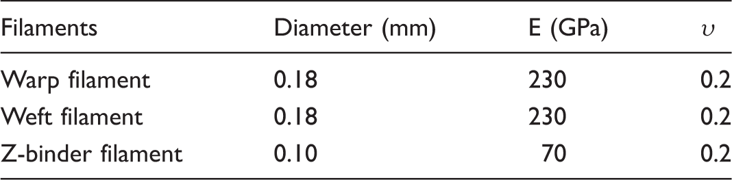
The parameters of the filaments.
Interlacing process
The Z-binder tensiles are applied to each fiber ends and that have the effect of straightening the Z-binder tows. The initial cross-section assemblies of fiber bundles are collapsed into diverse shapes seen in the sectioned textile samples as shown in Figure 3. The deformation of cross-section is caused by the interaction between the tows which further induce the contact among fibers. Therefore, the interactions between fibers play a significant role in the forming process.
Cross-section shapes of tows after deformation processes.
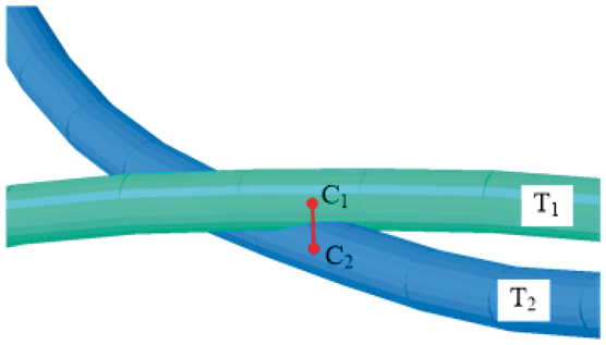
This forming process is implemented in commercial software Abaqus. Finite-sliding contact algorithms have been considered in this model and classical Amonton–Coulomb law with a constant isotropic frictional coefficient is used. If contact occurs between fibers, the physical condition would be either sticking or sliding. Sticking would happen if
Intersection between two fiber filament in 3D space.


Sliding would happen if

Contact frictional coefficients of each contact pairs.

After interlacing process, these three sets of tow achieve a dynamic balance and a 3D woven fabric architecture is obtained as shown in Figure 5. However, this fabric architecture which is at the scale of filament cannot directly use for the mechanical prediction of 3D woven composite. Therefore, a further treatment is needful to convert the fabric architecture into a finite element model.
3D woven fabric architecture.
Finite element model
Voxel mesh generation
The periodicity of the fabric architecture is taken into account for the definition of the mesoscale representative unit cell (meso-RUC). Therefore, the entire fabric architecture can be represented as a continuous assemblage of the meso-RUC. The fabric architecture is trimmed by four planes normal to the X-direction and Y-direction as shown in Figure 6. Homogeneous voxel meshes are generated according to the dimensions of the meso-RUC.
Definition of a unit cell. (a) Top view of the 3D woven textile. (b) Textile unit cell. (c) Homogeneous voxel meshes.
Then, it is necessary to determine that each voxel mesh belongs to either tows or resin matrix for the heterogeneous material. An element recognition algorithm is proposed to identify the mesh effectively. The main principle of this algorithm is to judge whether the voxel mesh includes fiber points. If there is no fiber point in the voxel mesh, it would be regarded as a resin matrix element. Otherwise, it would be regarded as a tow element. The fiber body is described by the fiber trajectory points and corresponding cross-section contours in the textile model. However, the fiber trajectory points are too sparse to identify all meshes in the fiber body and misjudgments can be induced as shown in Figure 7(a). Therefore, it is required to fill the fiber body with enough points. Two steps are carried out to generate fiber points to avoid misjudgments. The first one is that several interpolated points are inserted between the two trajectory points to obtain intensified trajectory points. The second one is that circumferential points with uniform distribution in the cross-section contour which corresponds to those intensified trajectory points are generated as shown in Figure 7(b). Besides, all fiber points distributing in a cross-section are attached with a direction property which is equal to the orientation of corresponding intensified trajectory points. The density of fiber points is controlled according to the voxel mesh size.
Fiber points amending for the mesh identification. (a) Before amending. (b) After amending.
However, a scenario that fiber points belongs to more than one tow set appear in the same voxel mesh, which is illustrated in Figure 8. The distance between fiber point and mesh center point is calculated and the point with minimum distance is used to determine the element type. The procedure described above is successfully used to generate the finite element model of 3D orthogonal woven-reinforced composite.
Scenario that fiber points belonging to more than one tow sets appear in the same voxel mesh happens in the critical contact areas.
Local material orientation
As shown in Figure 9, the fiber orientation would diverge from tow path due to the pinching effect at crossover points. A local material orientation for an accurate and reliable calculation of highly anisotropic composite materials is proposed in the present model. There is a fiber point inside voxel element belonging to tows as mentioned in ‘Voxel mesh generation’ section. The major principal axis of local material coordinate for the voxel element is defined by the unitization of the direction of fiber point. The second principle axis is taken in arbitrary vertical direction to the major principle axis. The third principle direction requires no manual configuration which is calculated as the vector product of the first two. The assignations of the local material orientations for each voxel element which belong to tows are exhibited in Figure 10.
Non-parallel fiber orientations in the 3D woven textile model. (a) Warp tow. (b) Weft tow. (c) Z-binder tow. The assignations of the local material orientations for each voxel element which belongs to tow: (a) warp tow, (b) weft tow, (c) Z-binder tow.

Material property
Material constitutive relationship
Elements in the composite unit cell belong to either pure resin or impregnated tows. The resin phase is prescribed by the property of isotropic, while the impregnated tows are assumed to be transversely isotropic property. To determine the mechanical properties of the impregnated tows, a micro-scale representative unit cell (micro-RUC) model is constructed with fiber volume fracture of 50.0% as shown in Figure 11. The material properties of carbon fiber and resin are summarized in Table 4. The predicted effective properties of impregnated tows are listed in Table 5.
Geometry of micro-scale repeating unit cell model (micro-RUC). The material properties of carbon fiber and resin (from manufacturer's data-sheets). Predicted effective properties of impregnated tows.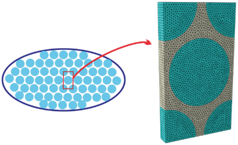


Damage initiation criteria
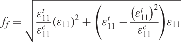
The damage initiation criteria for the impregnated tows are based on a strain-based continuum damage formulation [36]. The impregnated tow is assumed to be linearly elastic before damage occurs. In this case, two modes of damage in term of transverse matrix damage and longitudinal fiber damage are considered for the impregnated tows.
The damage state in transverse direction is given by

Damage initiation properties of impregnated tows and resin (MPa).

Damage evolution law
For the transversely isotropic constitutive property of impregnated tows expressed, the modulus stiffness can be written as follows

The transverse and longitudinal damage indicators 

Impregnated tow fracture energy (J/mm2).

The damage model is implemented using the user defined material subroutine (UMAT) and is connected with a commercial software packaged named as ABAQUS/Standard.
Results and discussion
Internal geometry comparing
In order to validate the finite element model, three cross-sections of the model are compared with microscope images of the composite sample. The cross-section views of the composite are shown in Figure 12. The cross-section images reveal that the upper and button layers of weft tows have some out-of-plane waviness at crossover points. The reason is that the adjacent weft tows at the crossover points sustain lateral force and experience significant shifting through the thickness.
Comparing of samples and voxel mesh model results at three mentioned cut plane, (a, b) along weft tow, (c, d) along warp tow, (e, f) along Z-binder tow.
Mean values of the cross-sectional area, two main dimensions of yarns (width and thickness) and aspect ratio.

Mesh dependency analysis
Detail fiber volume fractions of each set of tows in the model.

ele-fvf: element fraction of impregnated tow; fvf: effective fiber fraction in the composite material.
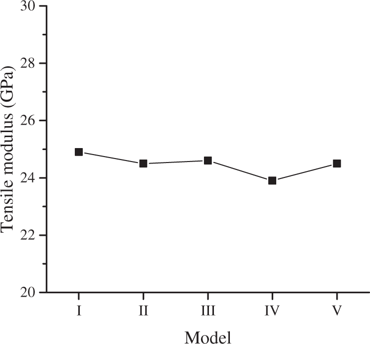
Tensile modulus with different mesh density.
Damage behavior
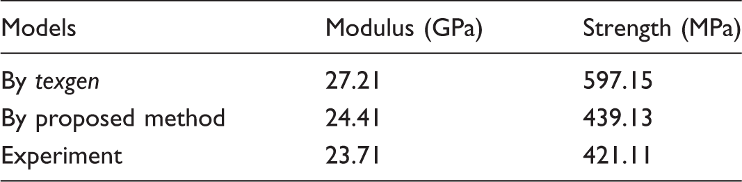
Predicted tensile properties of both models.

Stress–strain curves for each model alongside experiment for tensile warp loading.
Because of the heterogeneous nature of the textile reinforced composites, the stress distribution inside 3D woven composite is uneven. It can be seen from Figure 15(a) and (b) that the largest stresses areas concentrate on the warp tows. One of the warp tows in the unit cell is extracted from both the texgen model and the proposed model as shown in Figure 15(c) and (d). The stress distribution at about 0.005 strain for these two models is significantly different because of the different paths of warp tow. Warp tow longitudinal fractures are outlined as shown in Figure 15(e). We can find that the fiber ruptures of warp tow are jagged. This phenomenon reflects the difference load conditions which are induced by the misalignment of fiber filament in the warp tow. The warp tow path diverged at edges of tow for the proposed model. It is attributed to the lateral squeezing with up-layer weft tow that is originated from Z-binder tension. This lateral squeezing results in fiber misalignment which would reduce the carrying capacity of warp tows. However, the warp tow in the texgen model is constantly straight as shown in Figure 15(d) and all the filaments in the warp tow have the same reinforcement effect under the tensile loading. This is the reason for overestimation of tensile modulus and strength in the texgen model.
Stress distribution of the meso-RUCs and warp tows for each model. (a, b) The proposed model, (c, d) the texgen model, (e) damage morphology.
Although the warp tow sustains most of tensile loading, the weft tow which is perpendicular to the loading direction also plays a noticeable role during the loading process. The transverse damage indicator (SDV2) at 0.01 strain mainly distributed in the weft tows is shown in Figure 16. The element damages can be divided into two kinds in terms of intra-tow crack and interface debonding. Several resin cracks on the surface of the sample can be found in Figure 16(c). These resin cracks in the intercross regions of weft and Z-binder tows result in interface debonding, and that lead to intra-tow crack of weft in addition. Not only the areas occupied by the element in transverse damage state, but also the values of SDV2 in the proposed model are significantly larger than that in the texgen model. Therefore, the damage in the weft tow would progressively weaken the tensile response of the 3D woven composite. It may be the reason for the non-linear tensile behavior of the composite material in Figure 13. The most obvious weft tow structure difference between the two models could be the neglect of up-layer weft tow crimp at intercross point. This tow crimp is determined by the Z-binder tension and lead to various cross-section shapes. One of the weft cross-sections nearby the intercross point from two models was extracted and compared in Figure 16. The cross-sectional shape of the proposed model is irregular and more flattened which would result in more contact area with the warp tow. In addition, stress concentration is more likely to appear in the edge of the flattened weft tow edges, which would induce the weft tow transverse damage under the tensile load along the warp direction.
The distribution of transverse damage indicator (SDV2) for the meso-RUCs at 0.01 strain. (a) The proposed model, (b) the texgen model, (c) damage morphology.
Conclusions
The 3D woven fabric architecture was obtained by a dynamical method at filament level and an element recognition algorithm was proposed to convert a representative unit cell (RUC) into a finite element model. The comparison between cross-sections of numerical model and images of manufactured sample indicated that the tension (50cN) on Z-binder would cause internal micro-structure which includes diverged tow path and irregularity tow cross-sections. The stress–strain curves offered by the proposed model were found to be closer to the experimental data (error is within 5%) than that produced by texgen model (error is over 15%).
The tensile modulus and strength reduced due to the diverged warp tow path which is induced by the interaction between the tows during the weaving process. Moreover, the irregularity and compressed weft tow cross-sections around the intercross point are more likely to generate the transverse damage in the weft tow which would result in the non-linear tensile behavior of the composite material. The comparison of these two models can clearly demonstrate the effect of internal micro-structure on the damage behavior of the 3D orthogonal woven composites.
Footnotes
Declaration of conflicting interests
The author(s) declared no potential conflicts of interest with respect to the research, authorship, and/or publication of this article.
Funding
The author(s) disclosed receipt of the following financial support for the research, authorship, and/or publication of this article: This work was supported by the National Science Foundation of China (Grant No.51775514) and Zhejiang Provincial Natural Science Foundation of China (Grant No.LR18E050001).