
Abstract
In this work, a pulsating extensional stress induced melt mixer was developed. The compositions, structure, working principle, and melt mixing process of the device were introduced in detail. The mixer generated a full-process pulsating extension deformation effect on materials by the eccentric vane units and arc-shaped flow channels, which greatly promoted the dispersion and mixing of the materials. Polypropylene/carbon fibers (PP/CFs) composites were prepared by the new mixer, and the effects of different rotational speeds and mixing time on the properties of the composites were studied. The results showed that proper rotational speed and mixing time effectively promoted the dispersion of CFs in PP matrix, while the fibers still had long remaining lengths. As a result, the overall properties, especially the mechanical properties of the PP/CFs composites improved. When the CFs content was 30 wt.%, at the process parameters of 20 r/min and 2 min, compared with pure PP, the tensile strength (58.46 MPa) and modulus (1962 MPa) of the PP/CFs composite were increased by 78.6% and 263.3%, respectively.
Keywords
Introduction
Short carbon fibers (CFs) reinforced thermoplastics can exhibit excellent properties only after simple and efficient processes such as injection and extrusion, resulting in a wide range of applications.1–4 The properties of carbon fibers reinforced polymers (CFRP) are affected by three main factors: the condition of CFs (including content, remaining length, orientation, and distribution, etc.), the condition of the polymer matrix (including the degree of degradation, porosity, etc.), and the interface bonding between the matrix and CFs. The enhancement effect of CFs is closely related to the remaining length. The longer the length of CFs, the better the stress transfer by CFs in the matrix, which makes CFRP better disperse the stress to each part when it is stressed.5–8 The orientation and distribution of CFs in the polymer matrix also affect the properties of CFRP. In general, the orderly orientation and distribution of CFs can effectively promote the transfer of stress in the matrix, so that CFs can withstand the stress to the greatest extent.9–11 Besides, during the production of CFRP, process parameters such as temperature, rotational speed, processing time, and pressure have different degrees of influence on the polymer matrix, thereby affecting the overall properties of CFRP.7,12–14 Furthermore, the CFs act as a connecting bridge in the polymer matrix, so the bonding strength between CFs and matrix will directly determine the properties of CFRP. The surface treatment of CFs can increase the interface bonding strength and improve the mechanical properties of the materials.15–18
Different process methods and parameters have different effects on the remaining length, orientation, and dispersion of CFs, as well as the interface bonding between CFs and the matrix, which will ultimately affect the overall properties of CFRP.19–22 Melt mixing is one of the most used methods for the preparation of polymer matrix composites. Depending on the forms of the force that materials are subjected to in devices, processing equipment can be classified into those dominated by extensional flow and those dominated by shear flow. 23
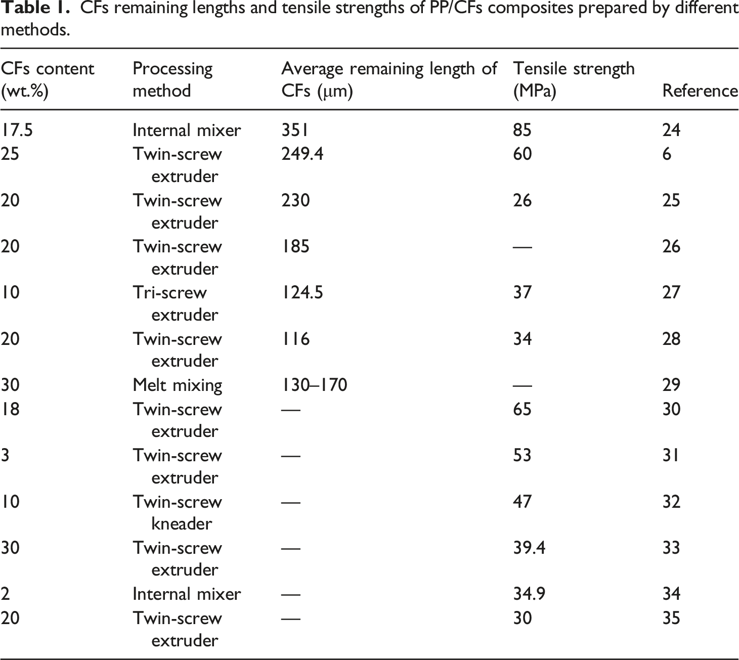
CFs remaining lengths and tensile strengths of PP/CFs composites prepared by different methods.
Studies have shown that the mixing devices dominated by extensional flow have efficient mixing performance.38,39 Rauwendaal40,41 developed a new device which generates a strong extensional flow by the conical groove on the screw flight. Duc 42 proposed a device that combines a single screw extruder with two extensional batch mixers, 43 which alternately receive the material extruded by the extruder and make the material converge/divergent flow in them. The experimental results showed all the mentioned devices effectively promote the dispersion of materials, but they only generate extensional flow in the local processing.
To enhance the dispersing and mixing effect of the extensional flow on materials in the whole processing, Qu 44 developed an eccentric rotor extruder (ERE), which can periodically generate volumetric extension deformation in the inner cavity of the stator. Zhai 45 used this device to prepare PP matrix composites, which had good compatibility and significant mechanical properties. Yin 46 and Yu 47 designed a laboratory-scale vane mixer (VM). Depending on the uniquely designed eccentric shaft and vanes to generate a periodic extensional flow, the VM realizes a short-process circulating flow of material, which effectively reduces the working space. The ERE and VM generated periodically changing pulsating extensional flow, which existed throughout the processing and acted on the material all the time, improving the dispersion efficiency of materials. However, these devices cannot keep the pushing stress and the flow direction of materials always in the same direction, which made the materials flow through sharp turns, and this was not conducive to the retention of fiber length. Therefore, they are not very suitable for the preparation of CFRP.
In this work, in order to keep the CFs a long remaining length while dispersing well, we developed a pulsating extensional stress induced melt mixer, which can produce a periodic compression-release effect on the materials and provide normal stress to the material throughout the whole processing process. The mixer can realize automatic materials discharge and self-cleaning under the forced conveying effect of the vane units, which means more convenient and efficient operation. The processing process of this mixer is close to the extrusion, which is convenient for industrialization. The PP/CFs composites were prepared by the mixer, and the effects of process parameters such as rotational speed and mixing time on the properties of composites were studied.
Pulsating extensional stress induced melt mixer
Components and structure
The main components and structure of the pulsating extensional stress induced melt mixer are shown in Figure 1, including the positioning sleeve, rotor, upper stator, lower stator, vanes, pins, and end cover. The main components and structure of the pulsating extensional stress induced melt mixer: (a) positioning sleeve, (b) lower stator, (c) upper stator, (d) end cover, (e) vanes, (f) rotor, (g) assembly relationship between rotor and vanes.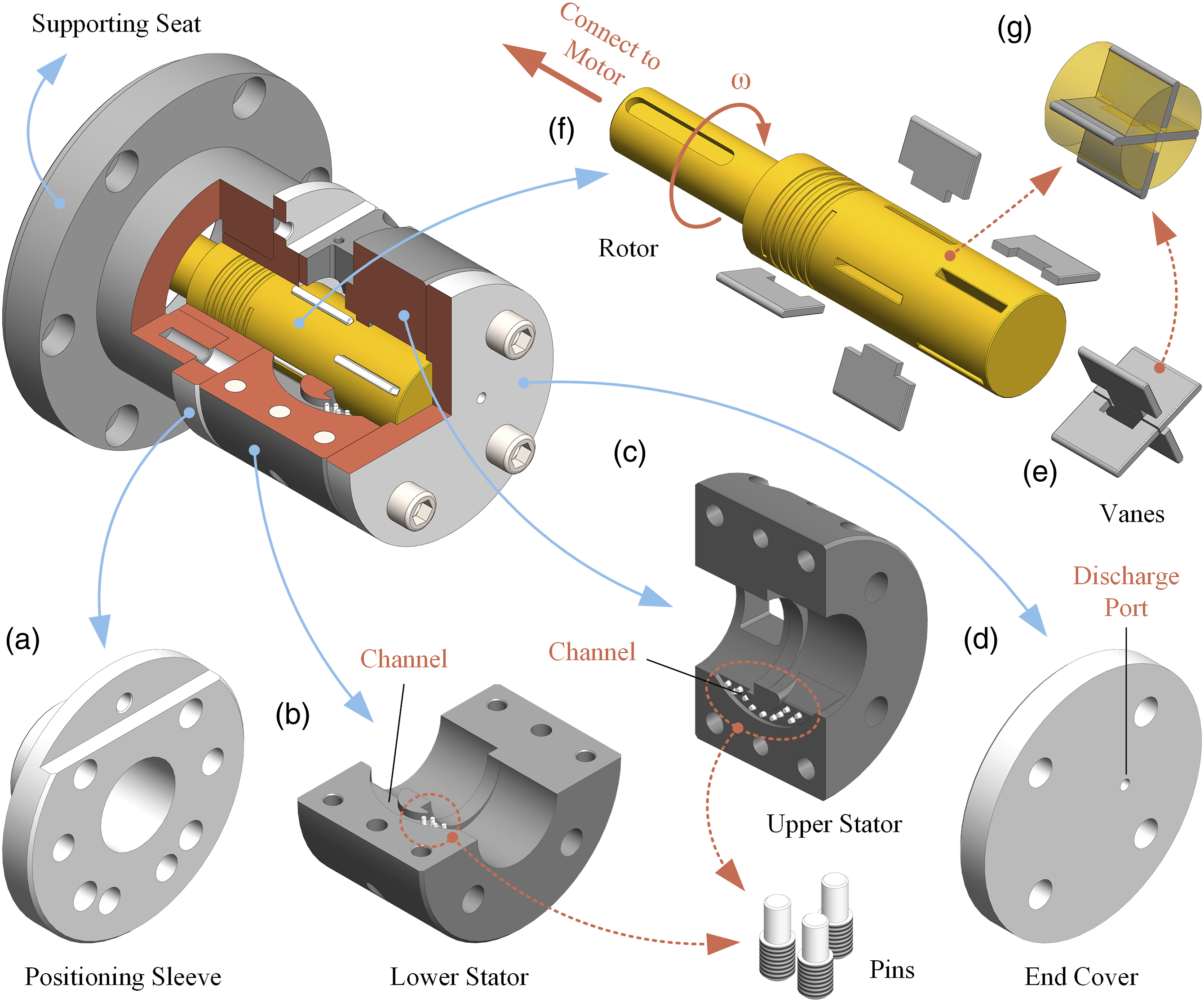
The positioning sleeve is installed on the supporting seat, and the rotor is connected to the motor through the inner hole of the positioning sleeve. The rotor has two sets of radial cross holes, each set of which has a pair of concave vanes and a pair of convex vanes installed, as shown in Figure 1(e)–(g). The stator consists of two parts, the upper and the lower, which fit with each other to form a complete circulating channel. When the rotor rotates, the vanes can reciprocate in the cross holes of the rotor, pushed by the inner surface of the stator.
The inner cavity of the stator is divided into three sections, as shown in Figure 2: the middle is a baffle with a circular hole, which is coaxial with the rotor and divides the cavity into two mixing chambers; the two mixing chambers on both ends are eccentric with the rotor, but the eccentric directions are opposite. Each mixing chamber, together with a part of the rotor and two pairs of vanes inside it, constitutes a vane mixing unit. The mixing units are connected by two arc-shaped channels with pins, on the upper and lower stators, as shown in Figure 1(b) and (c). Assembly and eccentricity relationship in vane mixing units.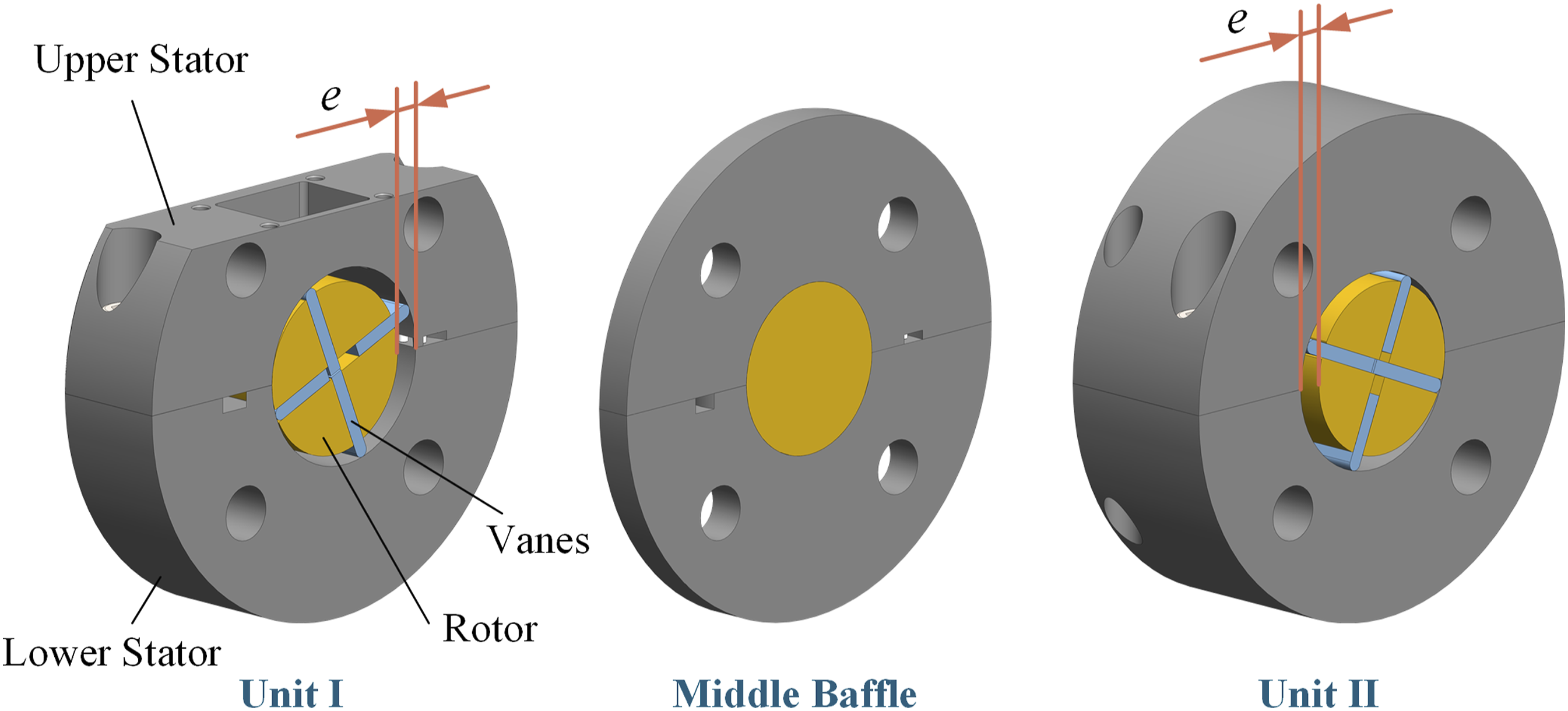
There is a discharge port on the end cover, as shown in Figure 1(d). When it is blocked with a plug, the positioning sleeve, stator, and end cover together form a closed cavity, where the material circularly flows between the two mixing units; and when it is opened, the mixed material is discharged.
Working principle and process
The schematic diagram of the flow of materials during the working process is shown in Figure 3. In each vane mixing unit, the rotor drives the vanes to rotate in the circumferential direction. The volume of the cavity enclosed by the vanes, rotor, and the inner surface of the stator is periodically changing with the rotation of the rotor. The region where the volume changes from large to small is called the convergent region (CR), and where the volume changes from small to large is called the divergent region (DR). The materials are fed from the feed port of Unit Ⅰ, go in turn through the DR and CR by the push of the vanes, then enter the arc-shaped channel of the lower stator, as shown in Figure 3(a). The schematic diagram of the flow of materials during the working process of the mixing system: (a) vane unit Ⅰ, (b) connection of vane units and channels, (c) vane unit Ⅱ, (d) extensional flow in vane units, (e) extensional flow in channels.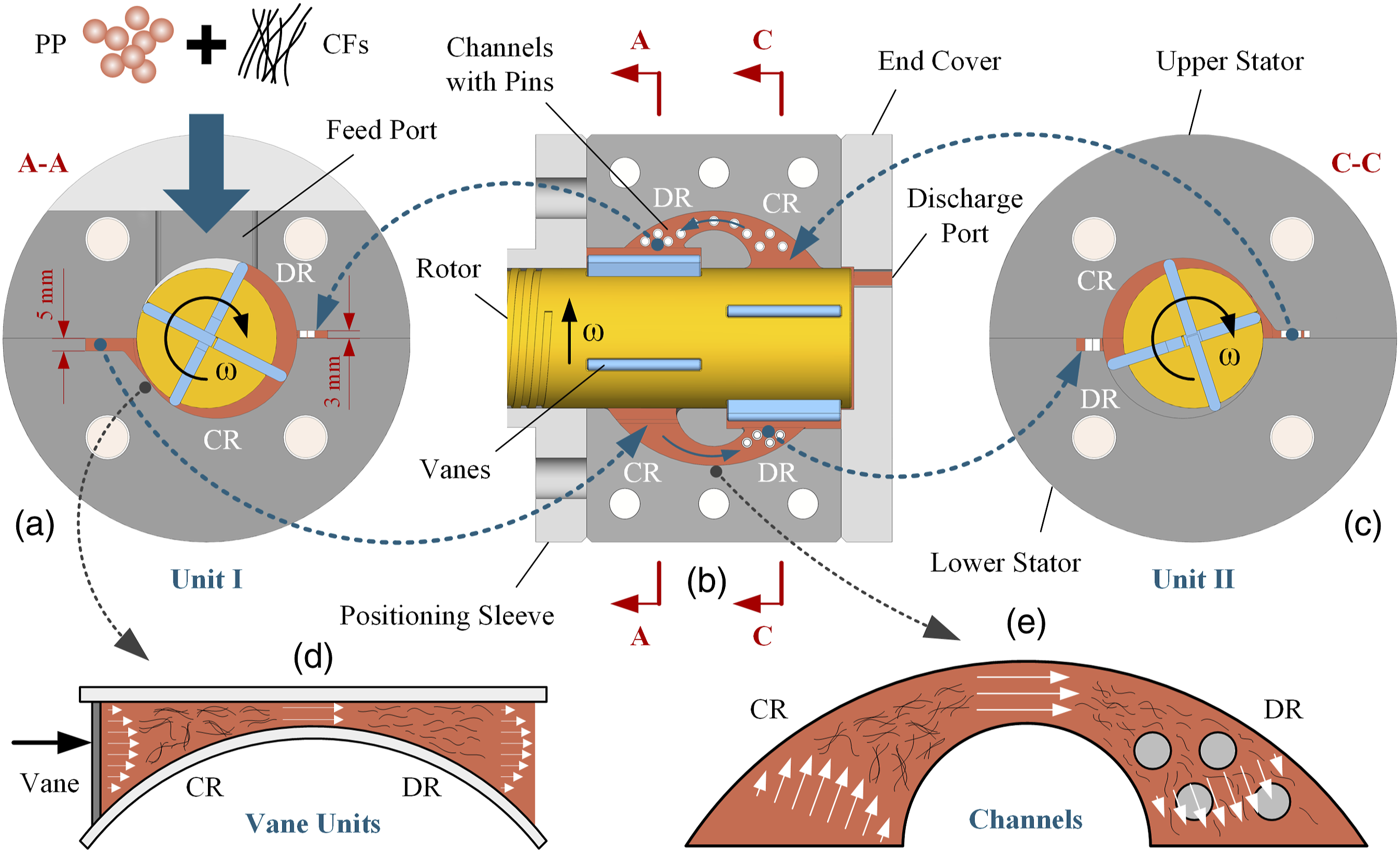
The channel of the lower stator can also be divided into CR and DR, and pins are installed in the DR, as shown in the lower half of Figure 3(b). The reason why there is no pin in the CR is to ensure enough time for the heating and plasticization of the solid materials, so that the materials can easily enter the channel. In this channel, the materials undergo a flow process from large volume to small, then from small to large, and are further dispersed by the pins in the DR, and finally enter the CR of Unit Ⅱ.
After entering Unit II, the materials go through the DR and CR by the push of the vanes again, then enter another arc-shaped channel of the upper stator, as shown in Figure 3(c). The shapes of the channels of the upper and lower stators are the same, but the heights are different, and the latter has pins from head to end, as shown in Figure 3(a) and (b). The pins have the effect of diversion, and the materials are continuously dispersed and converged in the gap of these pins, which can effectively promote the dispersion of the materials. When the materials enter the channel of the upper stator, the dispersing effect of the arc-shaped channel with pins can be fully exerted. In this channel, the materials are subjected to a process of continuously changing volume extension deformation from the CR to the DR, and finally back to Unit I, as shown in the upper half of Figure 3(b). Heretofore, a circular process has been completed.
When the discharge port at the end cover is blocked, with the rotation of the rotor, the materials continuously circulate in Unit I, the channel of the lower stator, Unit II, and the channel of the upper stator. When the melt mixing process is completed, the discharge port is opened, and the mixed materials are discharged.
When circulate in the inner cavity of the stator, the materials always flow in the direction of positive displacement. The cross-section of the cavity, which cyclically changes between gradually shrinking and gradually expanding, produces pulsating stress on the melt. The melt continuously diverges and converges with the periodic change of the volume of the stator cavity, and its flow velocity has a gradient in the flow direction, as shown in Figure 3(d) and (e), resulting in a pulsatile volume extension effect. The channels connect Unit I and Unit II, so that the extensional flow can generate in the whole cycle process, which promotes the dispersion of the materials.
The forces that break the CFs filler during melt mixing mainly come from between CF and CF, CFs and matrix, and CFs and the inner surface of the mixer. As shown in Figure 3(a)–(c), this structural design can keep the pushing stress and the flow direction of materials always in the same direction, which avoids the materials flow through sharp turns. Dispersing the CFs filler by the continuous extension deformation in the same direction can reduce the force on CFs comes from the shear flow between the matrix layers, thereby effectively promoting the dispersion of CFs in PP matrix while the fibers still had long remaining lengths, which can improve the overall properties of the CFs-reinforced composites.
Experiment
Materials
Polypropylene (PP): PPH-T03, density 0.91 g/cm3, melt index 2.5–3.5 g/10 min (230°C/2.16 kg), Sinopec, China.
Chopped carbon fibers (CFs): Tory T700, length 13 mm, tensile strength 4900 MPa, density 1.75 g/cm3, Toray, China.
Sample preparation
PP was dried in an oven at 80°C for 6 h, while CFs were calcined in a muffle furnace at 500°C for 4 h for high-temperature oxidation. Oxidation of CFs can generate oxygen-containing functional groups so that the surface roughness can be increased to enhance the bonding strength of CFs and polymer matrix.48,49
The new vane mixer was heated to 180°C and kept for 0.5 h, then PP was fed into it first, and CFs were added after the PP melted. The total mass of PP and CFs was 25 g, which kept the content of CFs at 30 wt.%. After the mixing time up, the blends were discharged and cooled to room temperature in the air. Then the blends were compression-molded into sheets (160 × 80 × 1 mm3) using a molding machine (KS100HR, Kesheng, China). After that, the sheets were cut into different standard specimens for testing.
Micromorphology observation
The prepared samples were frozen in liquid nitrogen for 0.5 h to brittle fracture. Then the fracture surface was sprayed with gold and observed under a scanning electron microscope (SEM, Quanta 250, FEI, America) at an accelerating voltage of 5 kV.
CFs lengths distribution statistics
A small number of samples were placed in crucibles and calcined in a muffle furnace for 4 h at 500°C. Then the remaining CFs were placed in glass dishes. After dispersing, the lengths of CFs were counted under an optical microscope (VMC250S, Zhitai, China), and 500 CFs were counted for each sample.
Rheological property test
The rheological properties were tested using a rotational rheometer (MCR302, Anton Paar, Austria) at a test temperature of 180°C and a scanning frequency of 0.1–100 rad/s.
Differential scanning calorimetry
The crystallization properties of prepared samples were investigated using a differential scanning calorimeter (DSC204C, Netzsch, Germany). The weight of each sample was 5 mg. In the protective nitrogen, the temperature was firstly raised from 30°C to 200°C at a rate of 10°C/min. After holding for 5 min, it was cooled back to 30°C at the same rate, After another 5-min hold, it was raised to 200°C at the same rate again. The crystallinity of the composites (X
c
) was calculated according to the following relation:
Tensile property test
According to GB/T1040.2-2006 test standard, the molded sheet was cut into standard samples and tested by a universal material testing machine (ETM 104B, Wance, China). All tensile tests were operated with a 50 mm/min tensile speed at room temperature (25°C), and five specimens were used in each test to obtain the average values. The standard deviation was calculated according to the following formula: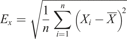
Results and discussion
Micromorphology analysis
The SEM images of the PP/CFs composites prepared at different rotational speeds are shown in Figure 4. The magnifications of the left and right columns are ×400 and ×1600, respectively. The mixing time is 2 min and the rotational speeds are varied from 10 r/min to 30 r/min. The fixed parameters in the later discussion with rotational speed as a variable are the same. SEM images of PP/CFs composites prepared at different rotational speeds.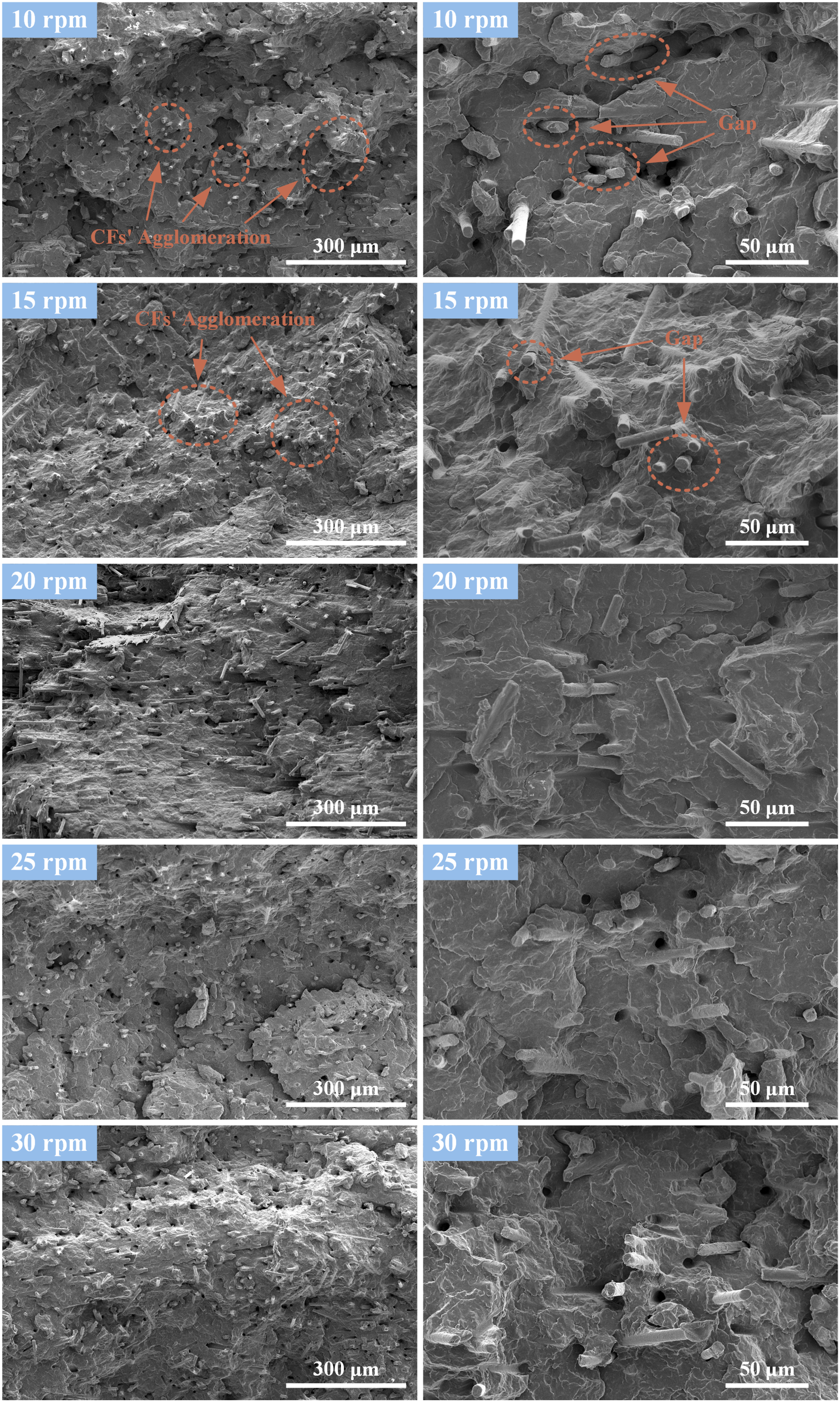
It can be seen from the left column of Figure 4 that when the rotational speed is 10 r/min and 15 r/min, the CFs in the composites have obvious agglomeration. But when the rotational speed increases above 20 r/min, the agglomeration decreases, while the spacing between fibers and the number of holes increases. The main reason is that with the increase of rotational speed, the pulsating extension effect to the PP/CFs composites is enhanced, which promotes the dispersion of CFs in the PP matrix and increases the number of broken fiber segments.
It can be seen from the right column of Figure 4 that when the rotational speed is 10 r/min and 15 r/min, there are some gaps between CFs and the PP matrix. With the increase of rotation speed, the bonding between CFs and PP becomes better, and there is no obvious gap. Moreover, the exposed parts of the CFs outside the PP matrix also decrease. The main reason is that the increase of the rotation speed makes the contact between CFs and PP more frequent during the mixing process, which is conducive to the adhesion of the PP matrix to the surfaces of CFs and promotes the chemical reactions between the active functional groups on the surfaces of CFs and PP. Thereby, the interface bonding force is improved.
The SEM images of the PP/CFs composites prepared with different mixing time at a magnification of ×400 are shown in Figure 5. The rotation speed is 20 r/min and the mixing time are varied from 2 min to 6 min. The fixed parameters in the later discussion with mixing time as a variable are the same. SEM images of PP/CFs composites prepared at different mixing time.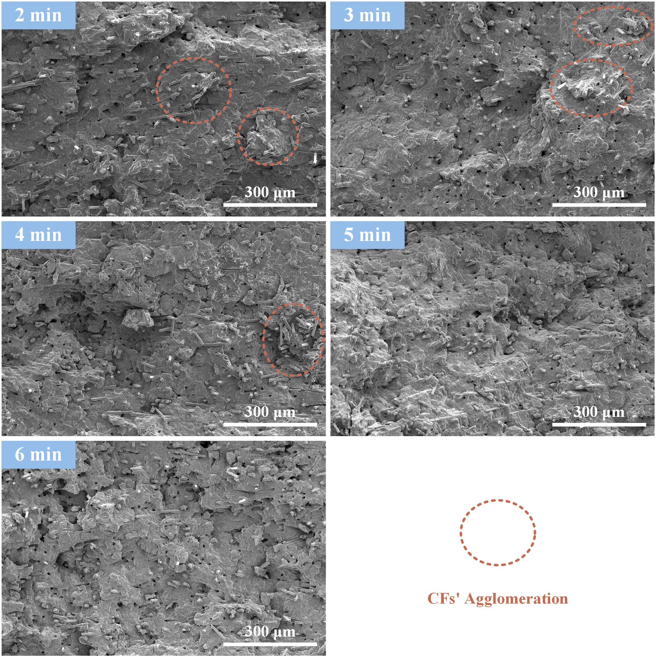
It can be seen from Figure 5 that when the mixing time is 2 min, 3 min, and 4 min, there are agglomerations of CFs in the composites. With the prolongation of mixing time, the CFs are uniformly dispersed under the action of long-time pulsating extension deformation, so that the agglomeration of CFs decreases. The fiber segments and holes also increase, for which the main reason is that the CFs circulate more times in the mixer, so that the friction and collision between CFs and PP matrix, the inner surface of the device, and CFs themselves increase, which aggravates the fragmentation of CFs.
CFs lengths distribution
The lengths distribution and average remaining lengths of CFs in the PP/CFs composites prepared at different rotational speeds are shown in Figure 6. It can be seen that the distribution of CFs lengths is mainly concentrated in the range of 0.2–0.4 mm, and with the increase of rotational speed, the overall distribution range of CFs lengths moves to the shorter end. Meanwhile, the average remaining length of CFs gradually decreases with the increase of rotational speed, the maximum is 336.9 μm at 10 r/min, and the minimum is 265.6 μm at 30 r/min. Lengths distribution of CFs in PP/CFs composites prepared at different rotational speeds.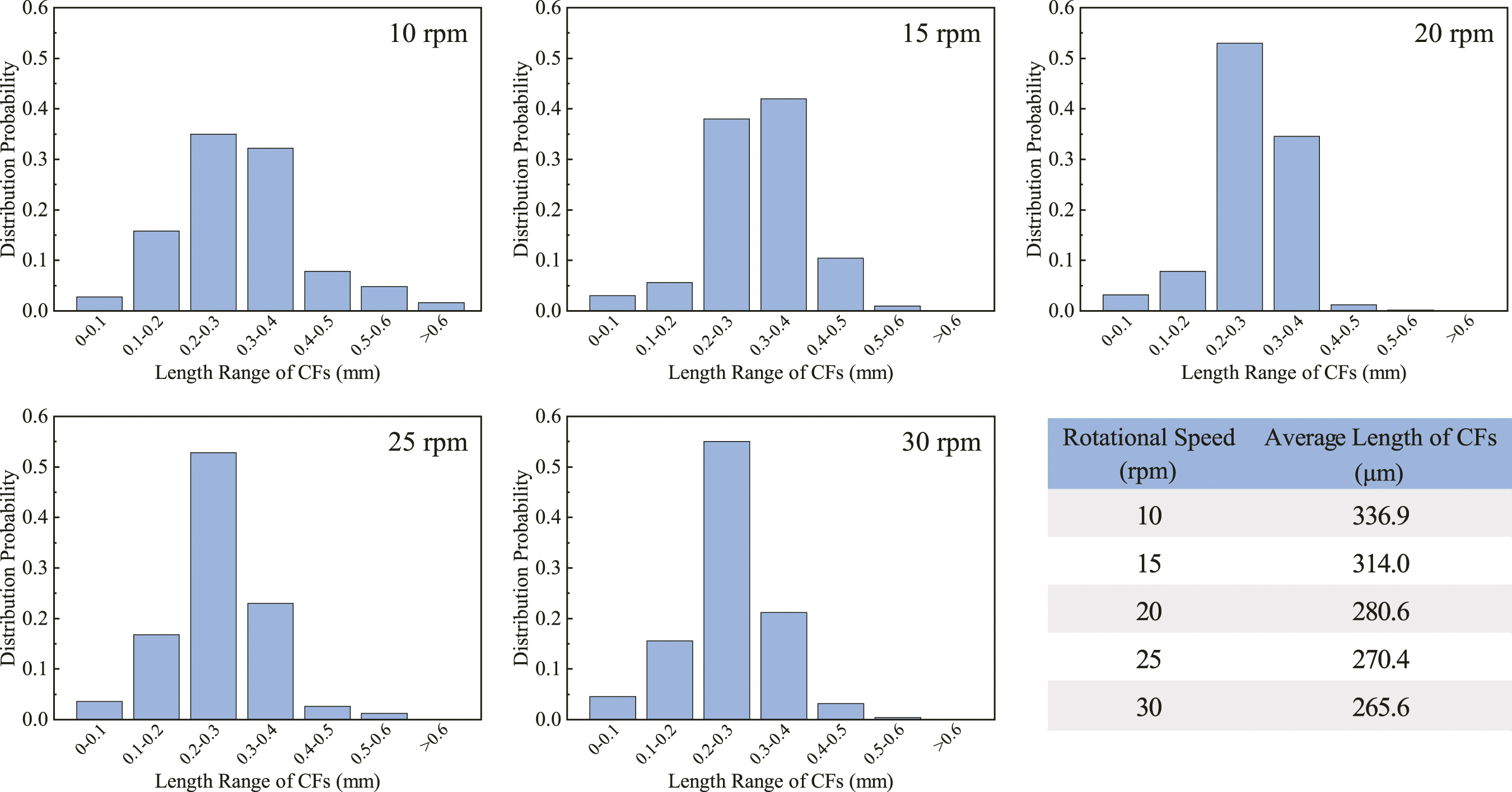
The effect of mixing time on CFs length is similar to that of rotational speed, as shown in Figure 7. Most of the CFs are distributed in the range of 0.2–0.3 mm, and the number of CFs above 0.3 mm gradually decreases with the increase of mixing time. The average remaining length of CFs also decreases with the increase of mixing time, the maximum is 265.6 μm at 2 min, and the minimum is 224.2 μm at 6 min. Lengths distribution of CFs in PP/CFs composites prepared at different mixing time.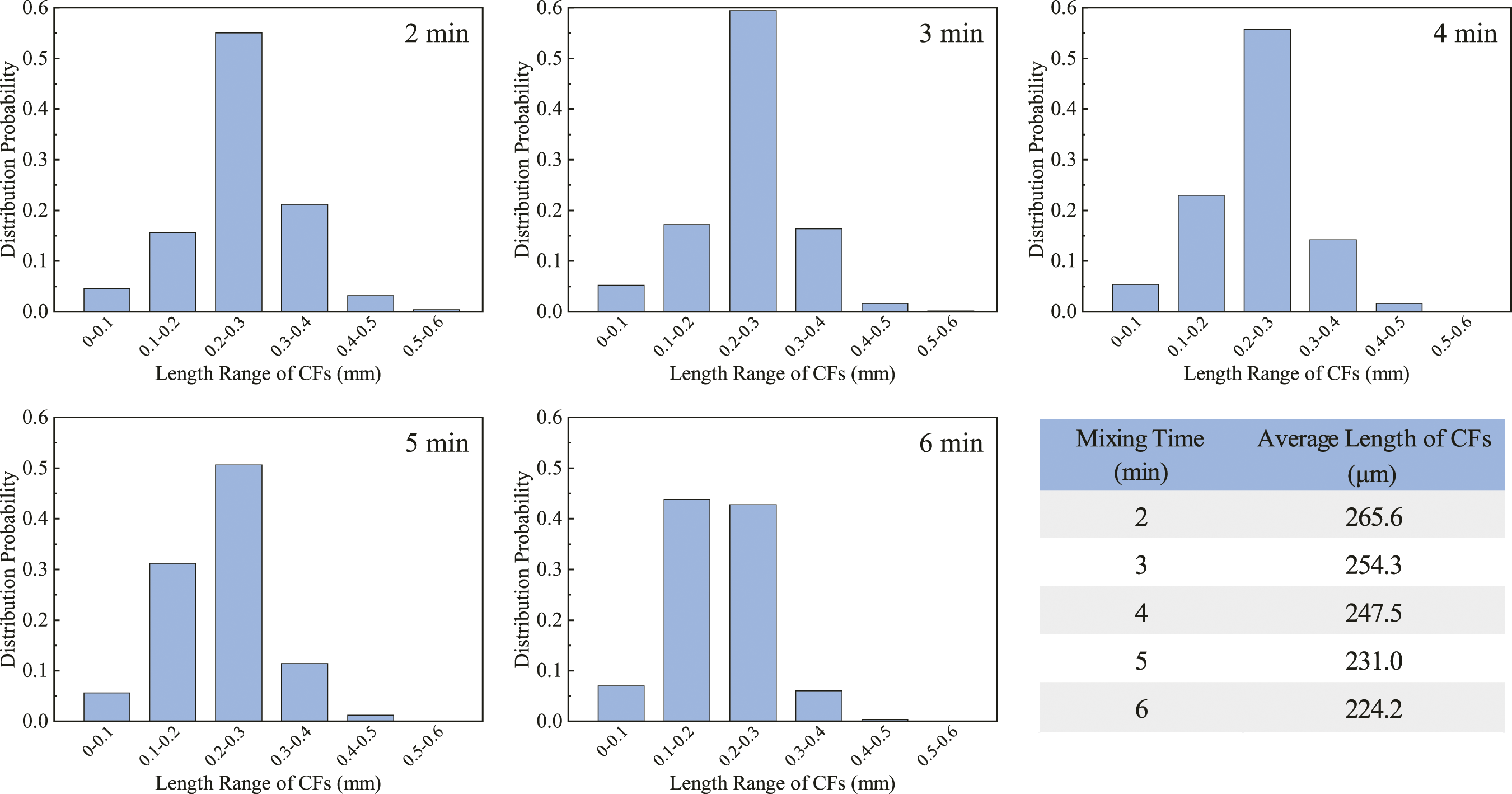
Increasing the rotational speed and mixing time will shorten the CFs’ length. The main reason is the same as the micromorphology analysis. The increase of rotational speed and mixing time increases the circulating flow times of the PP/CFs composites in the mixer, which enhances the pulsating extension effect to the PP/CFs composites, and increases the friction and collision between CFs and PP matrix, the inner surface of the device, and CFs themselves. As a result, the CFs breakage is aggravated and the average remaining length of CFs is reduced.
However, despite in the experimental conditions of maximum rotational speed (30 r/min) and maximum mixing time (6 min), the remaining length of the CFs is still longer than 220 μm, which is higher than most of the results in Table 1. It can be seen from Figure 4 that the CFs have already been dispersed well at the parameters of 20 r/min and 2 min. As shown in Figure 6, the remaining length of CFs at these parameters is 280.6 μm, which shows that the mixer can effectively disperse the CFs uniformly and retain the length of the fibers well.
Rheological properties
Figure 8 shows the effect of different rotational speeds on the rheological properties of the PP/CFs composites. It can be seen that the complex viscosity η
*
and storage modulus G′ of the composites gradually decrease with the increase of rotational speed. Rheological properties of PP/CFs composites prepared at different rotational speeds.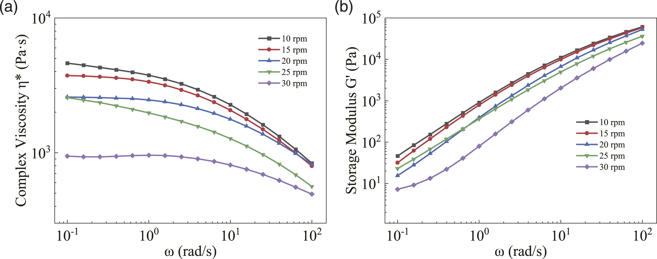
The uniformly dispersed CFs have less hindrance to the movement of PP molecular chains, and the rigid fibers can separate the PP molecular chains to reduce entanglement. 51 Besides, under the shearing force of the rotational rheometer, the CFs are oriented along the flow direction, which lubricates and orients the PP molecular chains. 52 With the increase of rotational speed, the dispersion of CFs in the composites increases, and fiber segments increase due to the fracture of CFs, which promotes the lubrication and orientation to the PP molecular chains, therefore reducing the η * and G′. Furthermore, when the rotational speed increases further, the pulsating extension deformation of the PP molecular chains is enhanced, which makes the chains degraded, and finally leads to the decrease of the η * and G′. 53 These observations are similar to the results of other studies on the rheological behaviors of fiber reinforced composites.54,55
The effect of different mixing time on the rheological properties of PP/CFs composites is shown in Figure 9. Similarly, the η
*
and G′ of the composites also gradually decreases with the increase of mixing time. The main reasons are also similar to increasing the rotational speed: On the one hand, prolonging mixing time increases the dispersion of CFs and the number of CFs segments, and also decreases the aspect ratio of fibers, which breakdowns the fiber-fiber network resistance, and makes the PP molecular chains easier to move.
53
On the other hand, a long mixing time leads to the degradation of the PP molecular chains. The combined effect of these two factors results in the decrease of the η
*
and G′. Rheological properties of PP/CFs composites prepared at different mixing time.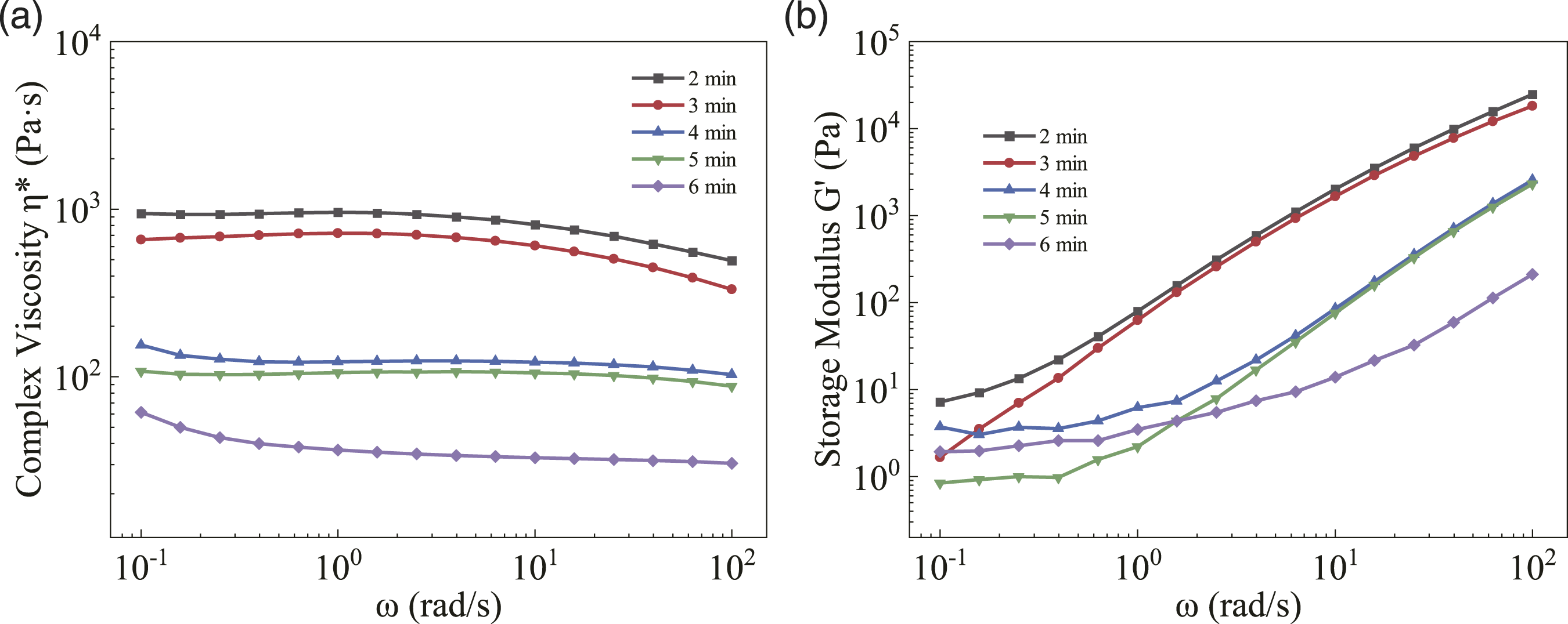
Crystallization properties
Figure 10 shows the melting and crystallization curves, as well as the corresponding crystallization property parameters of the PP/CFs composites prepared at different rotational speeds. It can be seen from Figure 10 that with the increase of rotational speed, the crystallization temperature (T
c
) shows an upward trend, and the melting temperature (T
m
) shows a downward trend, while the crystallinity (X
c
) increased from 27.1% at 10 r/min to 33.0% at 30 r/min. The main reason is that the increase of rotation speed makes the dispersion of carbon fibers more uniform and increases the CFs segments, which provides a lot of nucleation sites for the PP matrix and improves the crystallinity of the composites.
56
Melting curve (a), crystallization curve (b), and crystallization property parameters (c) of PP/CFs composites prepared at different rotational speeds.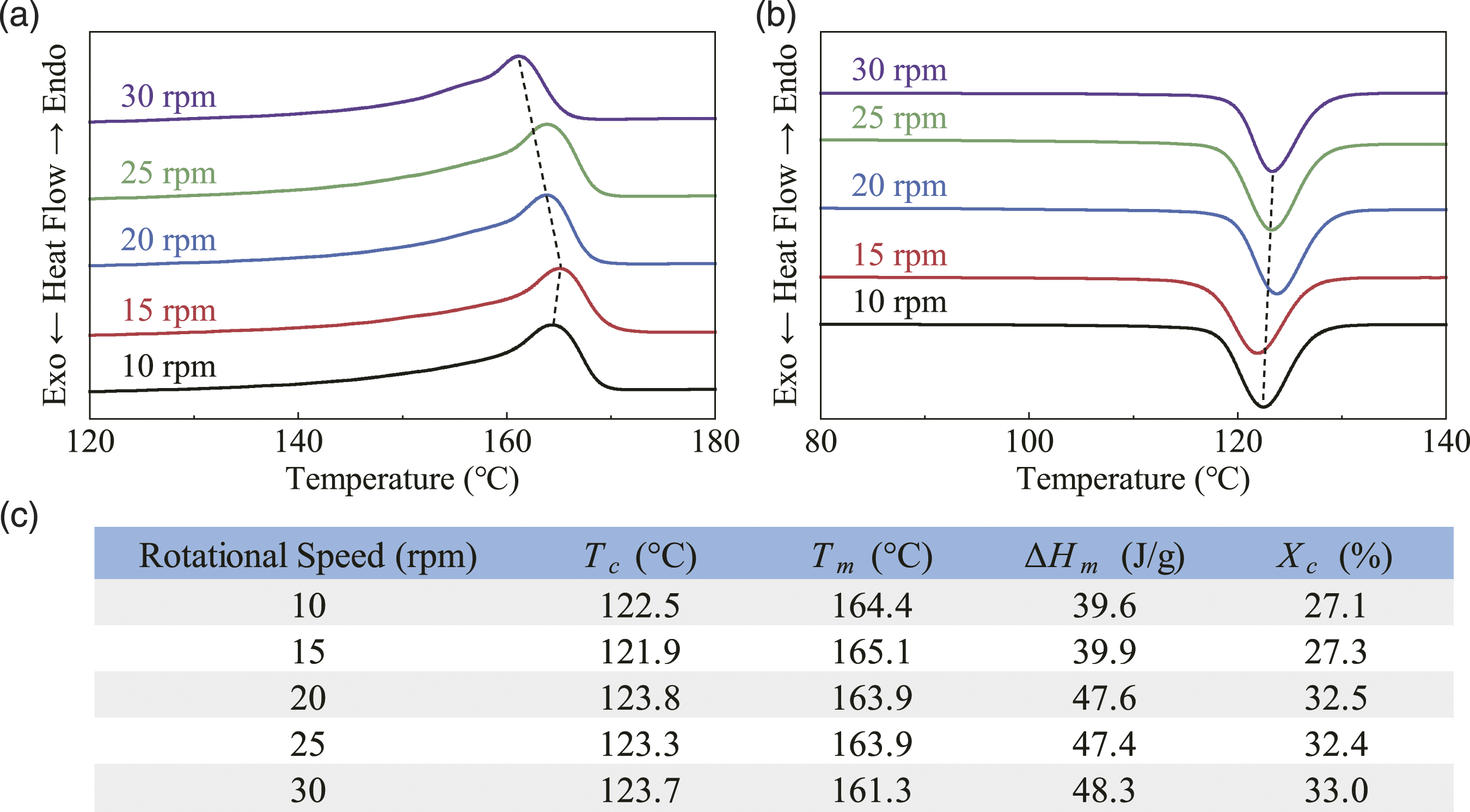
The melting and crystallization curves, as well as the corresponding crystallization property parameters of the PP/CFs composites prepared at different mixing time, are shown in Figure 11. It can be seen from Figure 11 that with the prolongation of mixing time, the crystallization temperature, melting temperature, and crystallinity all show a decreasing trend. The crystallinity decreased from 33.0% at 2 min to 23.6% at 6 min. Prolonging the mixing time promotes the uniform dispersion of CFs and increases the fiber segments, which promotes the crystallization of the composites. But at the same time, long mixing time also leads to the degradation of PP molecular chains. It can be seen from the rheological curves in Figure 9 that when the mixing time exceeds 2 min, the PP molecular chains have obvious degradation. The degradation effect is dominant in the influencing factors on the crystallization properties of the composites, so the crystallinity of the PP/CFs composites decreases. Melting curve (a), crystallization curve (b), and crystallization property parameters (c) of PP/CFs composites prepared at different mixing time.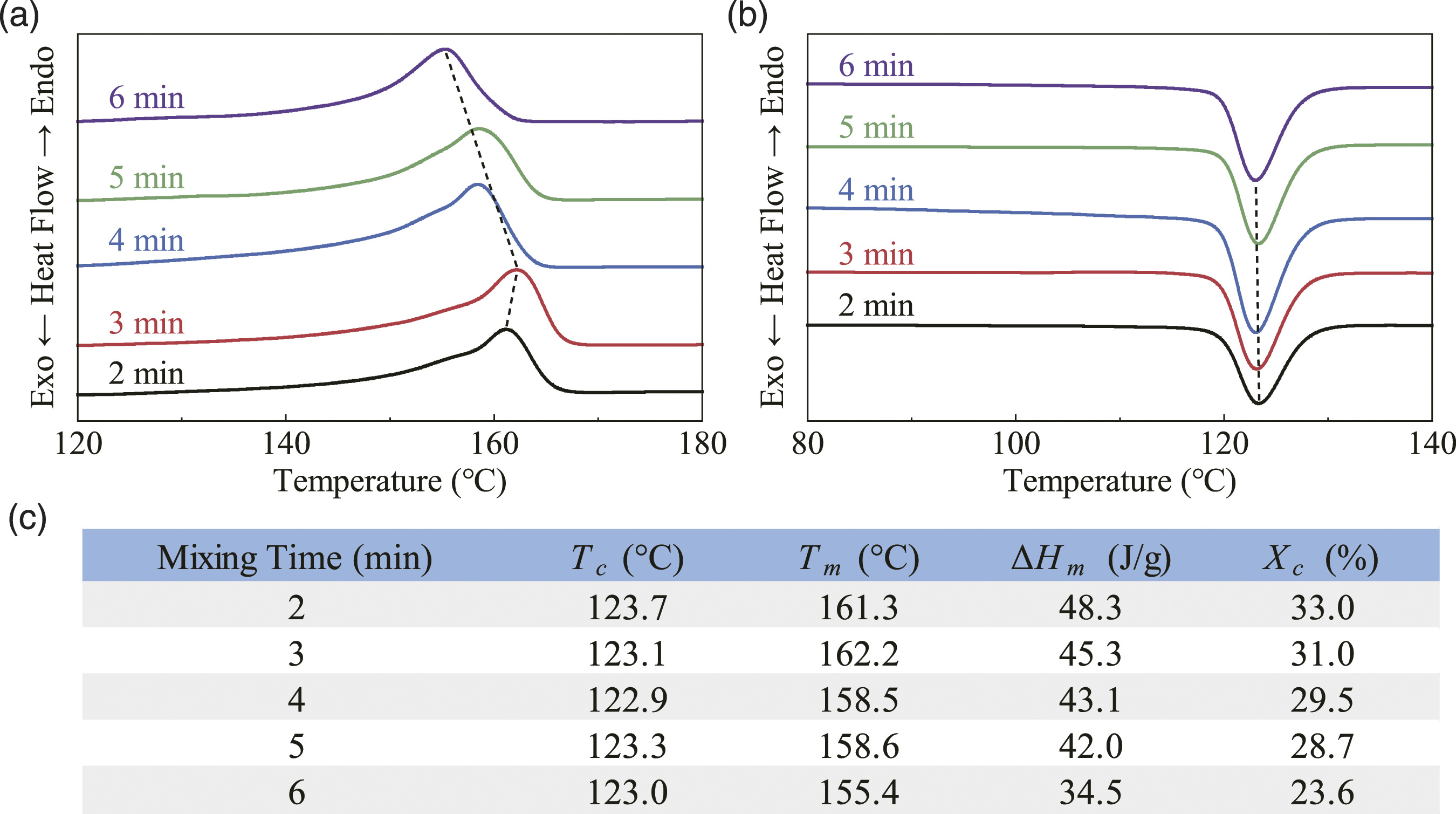
Mechanical properties
Figure 12 shows the tensile strength and modulus of the PP/CFs composites prepared at different rotational speeds. As shown in Figure 12, with the increase of rotational speed, both the tensile strength and tensile modulus show a trend of increasing first and then decreasing. The maximums, 58.46 MPa and 1962 MPa, are reached at 20 r/min, which are 78.6% and 263.3% higher than those of pure PP (32.74 MPa and 540 MPa), respectively. Tensile strength (a) and modulus (b) of PP/CFs composites prepared at different rotational speeds.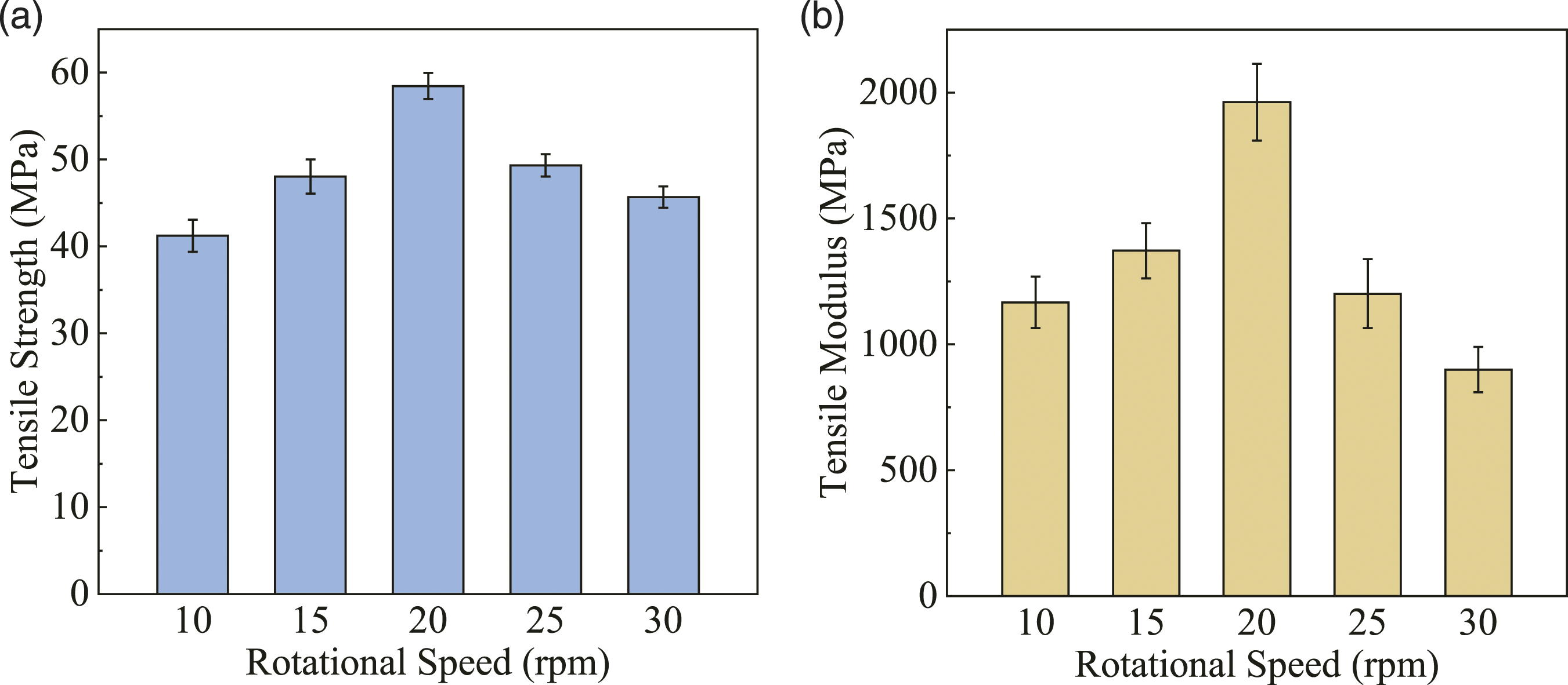
The increase of rotational speed promotes the dispersion of CFs in the PP matrix and reduces the agglomeration of CFs, so that the CFs can transfer and disperse stress in the PP matrix well. Besides, good dispersion brings good infiltration, which makes the matrix to better adhere to the surface of CFs, as shown in the right column of Figure 4, resulting in a better bond between CFs and PP matrix. This is beneficial to transfer the stress from the PP matrix to the CFs with higher strength, thereby improving the tensile properties of PP/CFs composites.
However, with the further increase of the rotational speed, the stronger pulsating extension deformation causes a certain degree of damage to the CFs and PP matrix. As shown in Figure 6, increasing the rotational speed reduced the average remaining length of CFs, from 336.9 μm at 10 r/min to 265.6 μm at 30 r/min. The decrease of CFs length weakens the ability to withstand and transfer stress. Moreover, the number of CFs segments increases, which provides a lot of nucleation sites for the PP matrix, as in the analysis of crystallization properties in Crystallization Properties. However, these nucleation sites are also stress concentration points in the PP matrix, which break the continuity of the matrix, thereby reducing the tensile properties of the composites. 57 Furthermore, as shown in Figure 8, the increase of rotational speed promotes the degradation of the PP matrix and reduces the viscosity of PP, which also weakens the tensile properties of the composites.
The tensile strength and modulus of the PP/CFs composites prepared at different mixing time are shown in Figure 13. It can be seen from Figure 13 that prolonging the mixing time will lead to a decrease in both the tensile strength and tensile modulus of the PP/CFs composites. The tensile strength (18.63 MPa) and tensile modulus (230 MPa) at 6 min decreased by 59.2% and 80.8%, respectively, compared with those at 2 min (45.70 MPa and 1201 MPa). Tensile strength (a) and modulus (b) of PP/CFs composites prepared at different mixing time.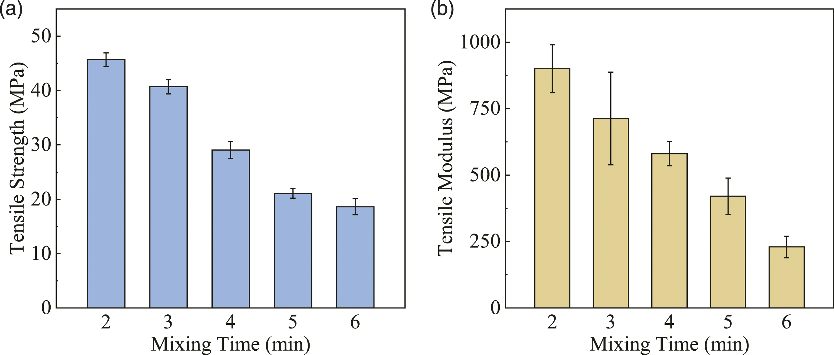
As the previous analysis, long mixing time leads to a significant decrease in the average remaining length of CFs, which is only 224.2 μm at 6 min, as shown in Figure 7. The fracture of CFs is not conducive to stress transfer but instead leads to an increase of the number of stress concentration points in composites, thereby reducing the tensile properties. Moreover, as shown in Figure 9, a long mixing time makes the PP matrix degrade seriously so that the tensile strength and tensile modulus of the PP/CFs composites are greatly reduced.
The tensile strengths of PP/CFs composites prepared by conventional methods are shown in Table 1, of which the data are the best results in these articles. In conventional processing methods, it is common to use continuous fibers or add compatibilizers to improve the mechanical properties of fiber-reinforced composites. When preparing short carbon fiber reinforced composites without compatibilizers, the tensile strength of PP/CFs composites prepared by this mixer is at a high level, and the processing time and flowing distance are shorter, which means more efficient.
Conclusion
In this work, a pulsating extensional stress induced melt mixer was developed, which produced a pulsating extension deformation effect on materials by the eccentric vane units and the channels with gradually changing cross-sections.
PP/CFs composites were prepared by the new mixer with different rotation speeds and different mixing time. The experimental results showed the new device, at proper process parameters, can effectively promote the dispersion of CFs in PP matrix, while the fibers still had long remaining lengths. The best tensile strength of PP/CFs composites reached 58.46 MPa, an increase of 78.6% compared with pure PP.
In summary, the mixer described in this work is a device that utilizes pulsating extension deformation effect to obtain good mixing efficiency, which can improve the overall properties, especially the mechanical properties of carbon fiber reinforced composites. This work provided a new method for the preparation of composite materials.
Footnotes
Declaration of conflicting interests
The author(s) declared no potential conflicts of interest with respect to the research, authorship, and/or publication of this article.
Funding
The author(s) disclosed receipt of the following financial support for the research, authorship, and/or publication of this article: This work was supported by the Foreign Cooperation Project of Science and Technology Program of Fujian Province, China (No. 2022I1005), the National Natural Science Foundation of China (No. 51873073), the Natural Science Foundation of Guangdong Province, China (No. 2021A1515010487, 2021A1515012609), and the Science and Technology Program of Guangzhou, China (No. 202002030350).