
Abstract
This study proposes a macroscopic finite element modelling and simulation approach considering the temperature dependency of both in-plane membrane and out-of-plane bending behaviours. This approach enables the investigation of the effect of the deformation mechanisms on the quality of the formed thermoplastic composite parts during the thermo-forming process. The temperature-dependent constitutive model of the in-plane tensional behaviour is considered linear, whereas the in-plane shear stiffness is modelled based on the nonlinear hypoelastic constitutive equation. The out-of-plane bending behaviour is considered by decoupling the membrane and bending method. A numerical simulation strategy is developed by implementing the ABAQUS software via a VUMAT subroutine. Moreover, a modified method is introduced for the qualitative and quantitative assessment of the wrinkling intensity generated in the forming process. The validated strategy is used to investigate the influences of the various temperature conditions of the forming process and the underlying mechanisms to optimise the thermo-stamping process.
Keywords
Introduction
Continuous fibre-reinforced thermoplastic composites (CoFRTPs) exhibiting excellent specific-strength and high specific-stiffness with low weight are promising materials for application in the automotive and aeronautical industries. Compared to thermoset composites, CoFRTPs have the advantages of fast manufacturing, high fracture toughness, low preservation condition requirement of prepregs, and high recyclability. Among the manufacturing methods of CoFRTPs, the thermo-stamping forming process is essential and has been widely used in engineering applications. During this process, two-dimensional (2-D) preformed composite laminates are fabricated into three-dimensional (3-D) CoFRTP components. Consequently, re-distribution of fibre orientations accompanied by forming defects such as wrinkling may occur during the forming process, which significantly affects the mechanical properties of the final CoFRTP part. Therefore, a comprehensive understanding of the deformation mechanism of materials during the thermo-stamping process is essential to reduce process-induced defects and enhance the structural quality of the final CoFRTP parts.
Previous studies have shown that the deformability of thermoplastic prepregs is highly dependent on the tool geometry and forming parameters, such as temperature and stamping speed.1–5 Based on the macroscopic scale of the material constituents, the generic deformation mechanisms of thermoplastic prepreg blanks normally include intra-ply behaviour (in-plane shear, tensile, and out-of-plane bending stiffness) and inter-ply behaviour (ply-tool and ply-ply slippage). Owing to the complexity of the deformability of the prepreg and its tendency to generate process-induced defects during thermo-stamping, virtual process simulation is more cost-saving method compared to the traditional “trial and error” method. In the early development of finite element (FE) modelling for thermo-stamping process simulations, most studies focused on in-plane behaviour such as in-plane shear and tension because in-plane shear stiffness is a crucial factor for the onset of wrinkling. 6 However, recent studies have shown that the out-of-plane bending stiffness should not be neglected, even though it is relatively small compared to the in-plane stiffness, because it plays a critical role in the size and shape of wrinkles.6–8 It has been demonstrated that modelling the bending stiffness of fabric or molten thermoplastic prepregs with conventional shell theories in commercial software is unrealistic.8–10 Consequently, more accurate methods that include the bending stiffness in forming modelling are currently a key research area in the forming simulation of CoFRTP.11–14
Furthermore, it is essential to consider the thermal-dependence characteristics in the thermo-stamping process modelling because the temperature distribution might not be uniform in the blank during the forming process. 1 Generally, most simulation models for thermo-stamping assume that the thermoplastic prepreg is in a molten state during the whole forming process.3,4,8,12,15 This is because the stamping step of the forming process is completed within a few seconds or tens of seconds, and the global temperature change of the blank is relatively small. For instance, for the thermoforming of carbon fibre reinforced PA composites, the stamping stage lasted about 10 seconds with a drop of about 20°C of the blank, which is still higher than molten point of PA6 resin. 8 However, the isothermal assumption might not be accurate locally because the temperature of the molten blank will cool rapidly when it comes into contact with the punching tool, which is of a lower temperature. Therefore, the temperature variation of the blank caused by the lower temperature punching tool and blank holder should not be neglected to realistically represent the temperature-dependent characteristics of the thermoplastic prepreg1,4,16 during the forming process.
Furthermore, most studies on the numerical simulation approaches of the thermo-stamping forming process are limited to carbon fibre or glass fibre reinforced composites. Because the mechanical properties of these types of fibre reinforcements are rarely affected by the forming temperature, the in-plane tensional property along the fibre direction is generally treated as a constant in thermo-stamping simulations.1,4 However, for polyolefin fibres, such as the ultrahigh molecular weight polyethylene (UHMWPE) fibre adopted in this research, the experimental results17,18 indicated that the thermal dependency of the tensional property along the fibre direction should be considered because of the lower melting point of the reinforcement. Furthermore, Machado et al. 4 performed a thermo-stamping simulation that only considered in-plane shearing stiffness under non-isothermal conditions with a one-layer shell element model. It is concluded that the use of a one-layer shell element model results in a far too high out-of-plane bending stiffness which can be unrealistic because the out-of-plane and in-plane tensile properties are coupled. The temperature-dependent simulation model based on decoupling the membrane and bending (DMB) method developed in this study is the response to the aforementioned problems identified in previous studies. 4
In this study, a macroscopic FE model for the local stamping stage of the thermo-stamping process considering the thermal dependency of both the in-plane membrane and out-of-plane bending behaviour was developed. The thermally dependent constitutive model of the in-plane tensional behaviour is considered linear, whereas the in-plane shear stiffness is modelled based on the nonlinear hypoelastic constitutive equation. Out-of-plane bending behaviour was considered by DMB method. Then, the forming simulation model considering the thermal dependency for both in-plane behaviour (in-plane shear stiffness and tensional modulus) and out-of-plane behaviour (bending stiffness) was established based on the parameterised results from experiments and the DMB method. In the second part, qualitative and quantitative approaches to describe the wrinkling intensity are introduced using a nodal modified mean curvature and a modified mean curvature estimation method, respectively. Finally, out-of-plane bending stiffness characterisation simulation and hemisphere geometry forming simulation were used to validate the effectiveness of the DMB method and the proposed simulation strategy. Furthermore, the influence of the punching tool and blank holder temperatures on the forming quality of the CoFRTP part was investigated.
Temperature-dependent simulation strategy of thermo-stamping process
Decoupling of in-plane membrane and out-of-plane bending behaviour strategy
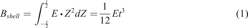
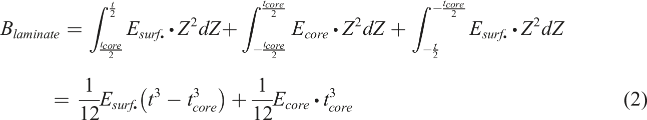
In traditional forming simulation methods, the shell element approach is commonly adopted directly to model a material with thin thickness and high bending stiffness characteristics, such as in metal punching forming. For the conventional shell element, the out-of-plane bending stiffness is calculated using the in-plane tensile stiffness which is considered as a coupled material property. The equation for the out-of-plane bending stiffness can be expressed as
Previous studies6,19,20 have reported that owing to the coupling of the in-plane tensile and out-of-plane bending stiffness, the one-layer shell element approach is not sufficiently accurate to model the bending behaviour, especially for the draping of dry fabric and the thermo-forming of thermoplastic composites. Therefore, decoupling of the membrane and out-of-plane bending stiffness should be considered to avoid unrealistic bending behaviour in the one-layer shell approach. Based on the laminate theory, Dobrich et al.
11
presented a method of decoupling the membrane and bending behaviours for non-crimp fabric (NCF) materials. This method was further developed by applying three-layer lay-up shells to describe the out-of-plane bending stiffness nonlinearity during forming; however, only a single integration point was considered in the core layer to reduce the total bending stiffness of the laminate.10,21 In this study, as shown in Figure 1, a three-layer lay-up shell method with three integration points in each layer along the thickness direction was developed to decouple the in-plane membrane and out-of-plane bending behaviour. Consequently, the desired bending stiffness of the laminate could be obtained by re-assigning the Young’s modulus in each layer in a manner similar to that used in previous studies.10,11,21 The bending stiffness of the laminate Laminate layup model for DMB method.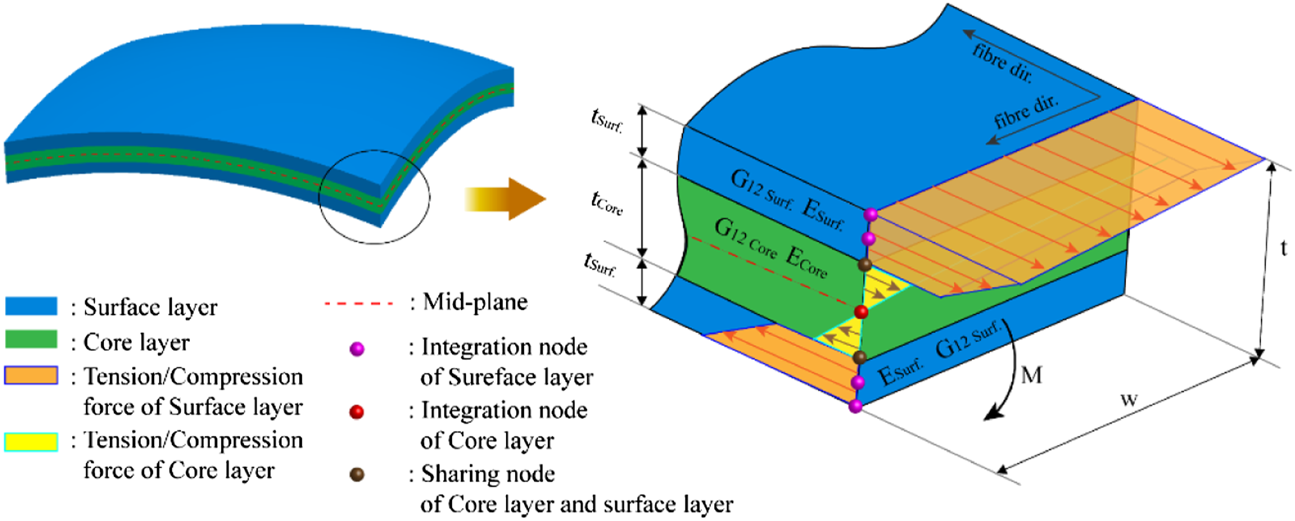
Utilising the rule of mixtures of the classical laminate theory, the Young’s modulus

Similarly, the in-plane shear stiffness of the laminate

By implementing the strategy illustrated in Figure 1 and outlined above, the out-of-plane bending stiffness of the blank can be obtained more accurately by assigning various tensional moduli to each layer with different thicknesses. In addition, the thermal dependency of the bending stiffness can be evaluated by considering the non-isothermal tensional modulus in the forming model. The details of this approach and the temperature-dependent strategy of the in-plane shear modulus are presented in the following sections.
Temperature-dependent constitutive of in-plane membrane behaviour
To accurately model the in-plane deformation characteristics, both the material properties and geometry-induced nonlinear deformation features should be considered in the constitutive equations. 22 Therefore, the strain rate- and temperature-dependent deformation behaviours of thermoplastic composites during the forming process should not be neglected during material characterisation. Consequently, the hypoelastic constitutive equation proposed by Machado et al., 4 including rate- and temperature-dependency, is adopted in this research to model the in-plane shear behaviour, while a linear temperature-dependency equation calibrated at various forming temperatures is employed to describe the in-plane tensional behaviour of thermoplastic composites.
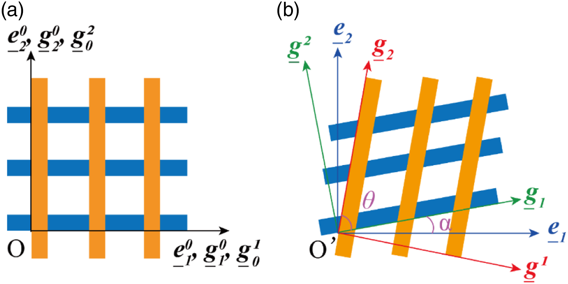
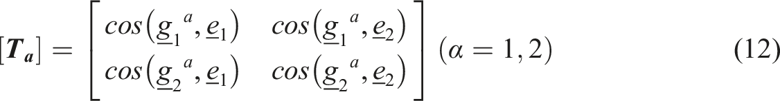
Figure 2 presents a schematic of the two orthogonal frames, that is, the fibre frame and material fixed frame, for a plain orthogonal structure with shear deformation. To incorporate the stress into the material fixed frame, the conventional hypoelastic constitutive equation described by the objective rate of the stress tensor Schematic of two orthogonal frames for orthotropic lay-up structure with shear deformation.
36

The Green–Naghdi objective rate
23
of the Cauchy stress tensor, considering the fibre rotation tensor, is given by

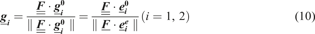
To describe the orientation between the fibre frame and the material fixed frame in the current configuration, non-orthogonal fibre frame covariant

The Green–Naghdi axes


Similarly, the fibre frame axes
After deformation, the strain increment

The change in the angle (radians)

The stress increment along fibre direction

To account for the thermal dependency of the material’s tensile behaviour during forming, the tensile modulus in the warp direction,

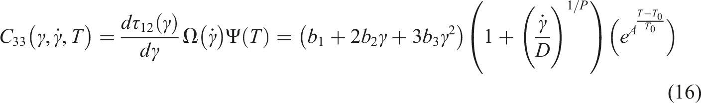
Considering the rate- and temperature-dependency of the in-plane shear behaviour, the in-plane shear stiffness
Based on the Hughes and Winget
25
formulation, the Cauchy stress in the fibre frame

The total stress in the Green–Naghdi frame

[The material model established above was implemented in a VUMAT user-defined subroutine in ABAQUS/Explicit. A flowchart of the implementation of the thermally dependent linear in-plane tensional modulus, as well as the rate- and temperature-dependent hypoelastic material model, is presented in Figure 3 Process diagram for the VUMAT subroutine.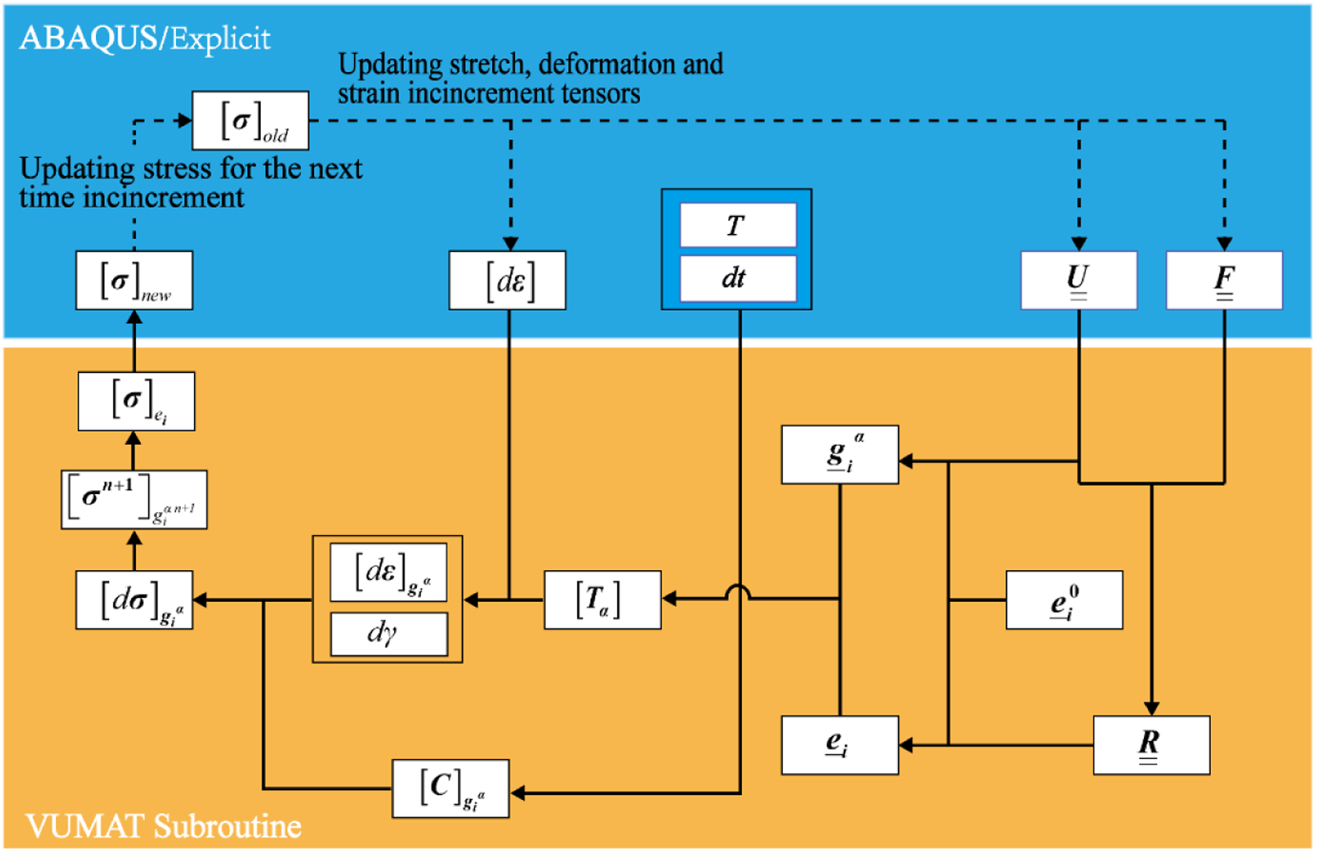
Material properties of UD laminate for simulation model
Temperature-dependent behaviour parameterization
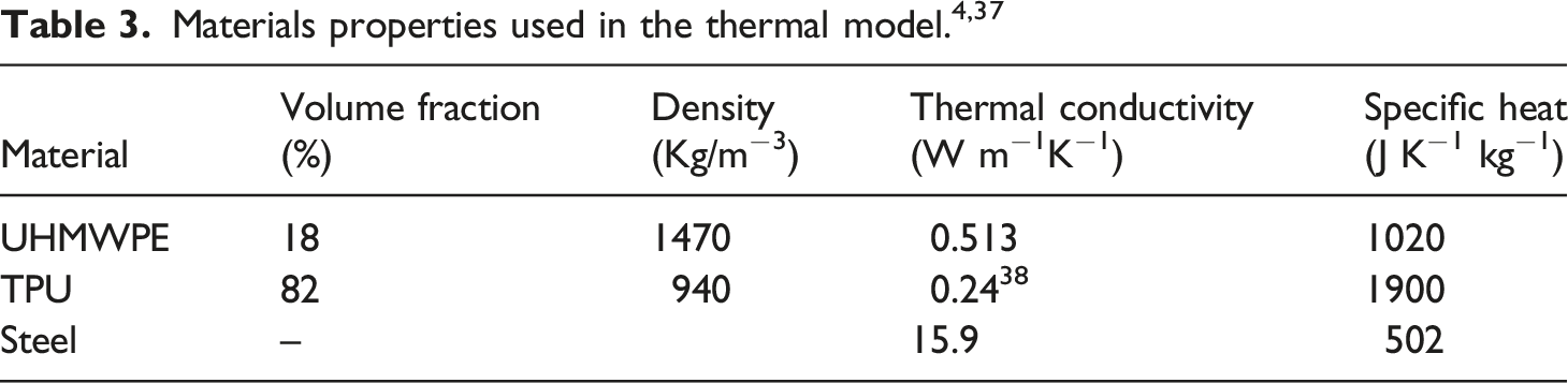
A thermoplastic composite material with UHMWPE fibre-reinforced thermoplastic polyurethane (TPU) matrix UD tape (Dyneema® HB80) was employed in this study. The matrix content (estimated, using the Rule of Mixtures, from the areal density, nominal sheet thickness, and respective matrix and fibre densities) ranges between 15% and 20% by weight (17.9 and 23.6% by volume). The single ply thickness is 0.148 mm, having roughly 10 fibres through the thickness and the sheets have an average areal density of 145 g/m2. The forming temperature is suggested below 130°C and the long-duration exposure is given from cryogenic to 70°C. 26 The relative temperature-dependent properties are reported in previous studies.17,26 Based on the thermal deformation results observed from the [0/90]2 cross-ply composite laminate during the thermo-stamping process, the fundamental material properties, including in-plane shear stiffness, tensile modulus, and the out-of-plane bending stiffness, were parameterised according to the characterisation results and incorporated into the simulation model.
In-plane membrane behaviour
Since the forming temperature stage of material was suggested from 70 to 130°C, the typical membrane behaviours at 70, 90, and 120°C were investigated.
26
Based on the material properties obtained by the standard test method ASTM-D5035 with an environmental chamber in a previous study,
17
the temperature-dependent tensile modules were fitted with equation (15) and are plotted in Figure 4. It should be noticed that the linear fitting equation is used here instead of the a third order polynomial equation provided by literature,
26
in order to decouple the in-plane tensile modulus and the out-of-plane stiffness easier. The linear fitting equation is validated work well and corresponding information could be found from Figure S1. Evidently, the tensile stiffness of the composite laminate decreases from 44.4 to 14.4 GPa when the temperature increases from 20 to 120°C because of the relatively low melting temperature (around 144–152°C
18
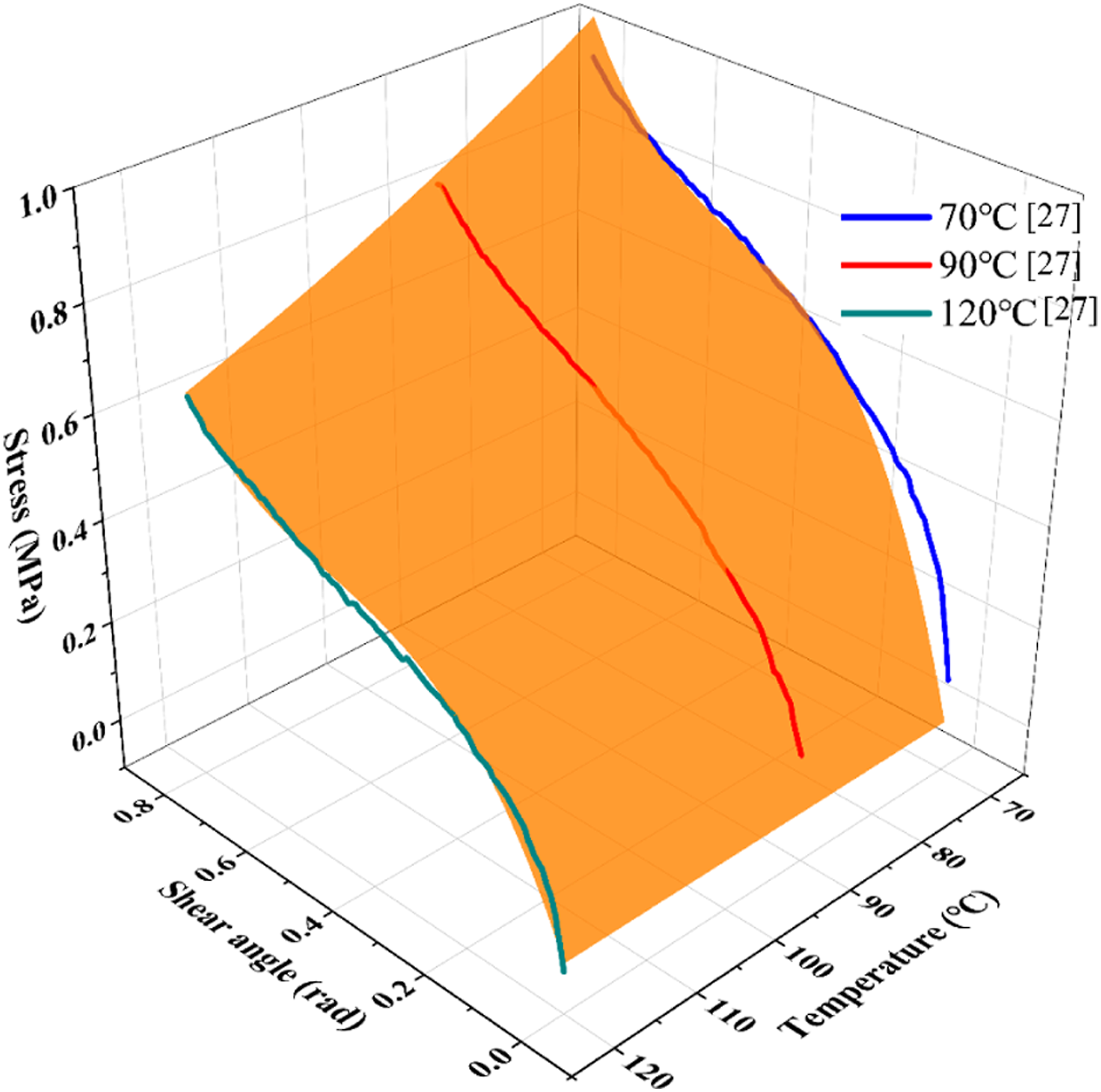
) of the UHMWPE fibres. This confirms that considering the tensile stiffness in non-isothermal conditions is necessary to model the out-of-plane bending stiffness to evaluate the thermal dependency. For the in-plane shear stiffness, a universal testing machine with an environmental chamber was used to perform picture frame experiments at elevated temperature conditions.
26
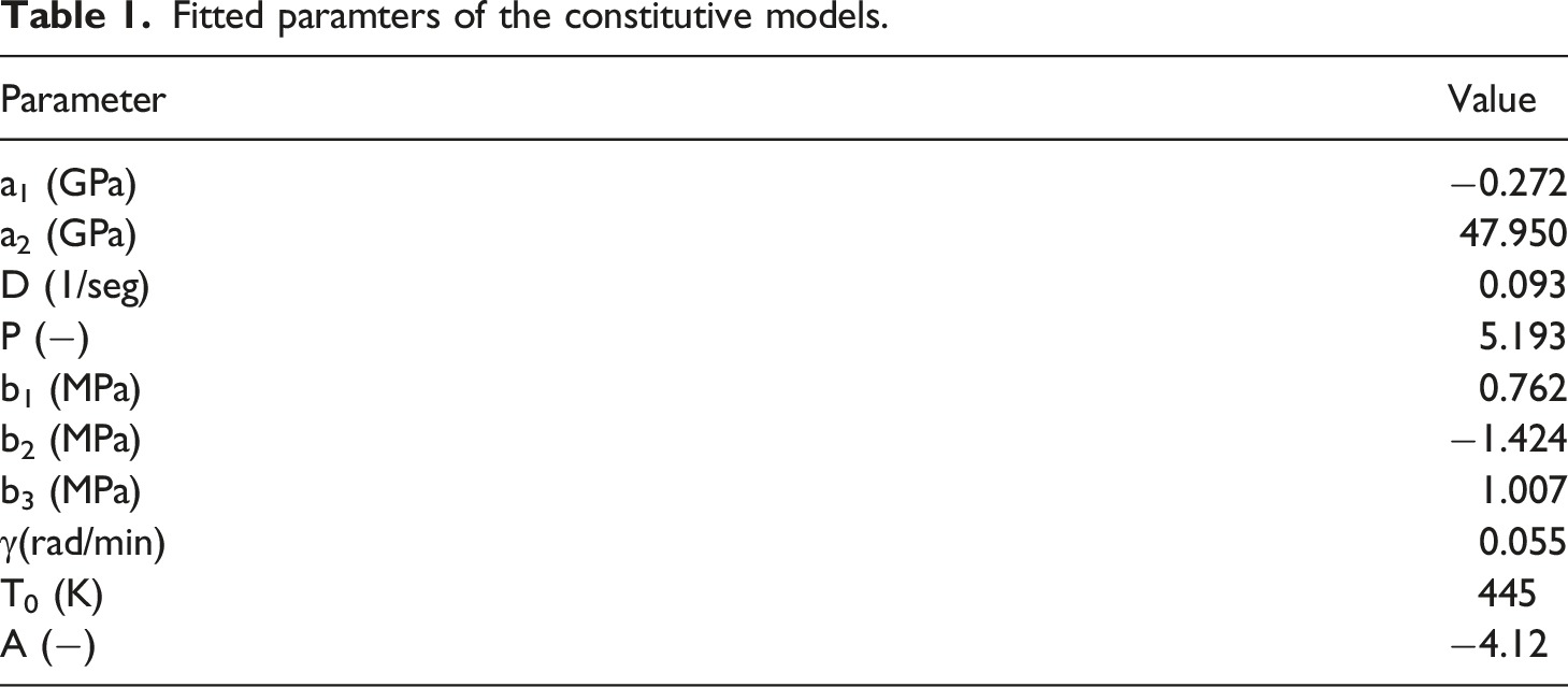
The experimental curves of the blanks at 70, 90, and 120°C were reorganised and fitted using equation (16), as shown in Figure 5. Concerning 2D graph of shear behaviors fitted by equation (16) displayed for 70, 90, and 120°C is compared to the experimental data as illustrated in Figure S2. It can be observed that the surface fitted by the polynomial model agrees well with the experimental curves. The fitted material parameters for equation (15) and (16), are listed in Table 1. Linear fit of thermal-dependent tensile modules under various temperatures. Comparison between experimental curves and fitted surface of in-plane shearing behavior. Fitted paramters of the constitutive models.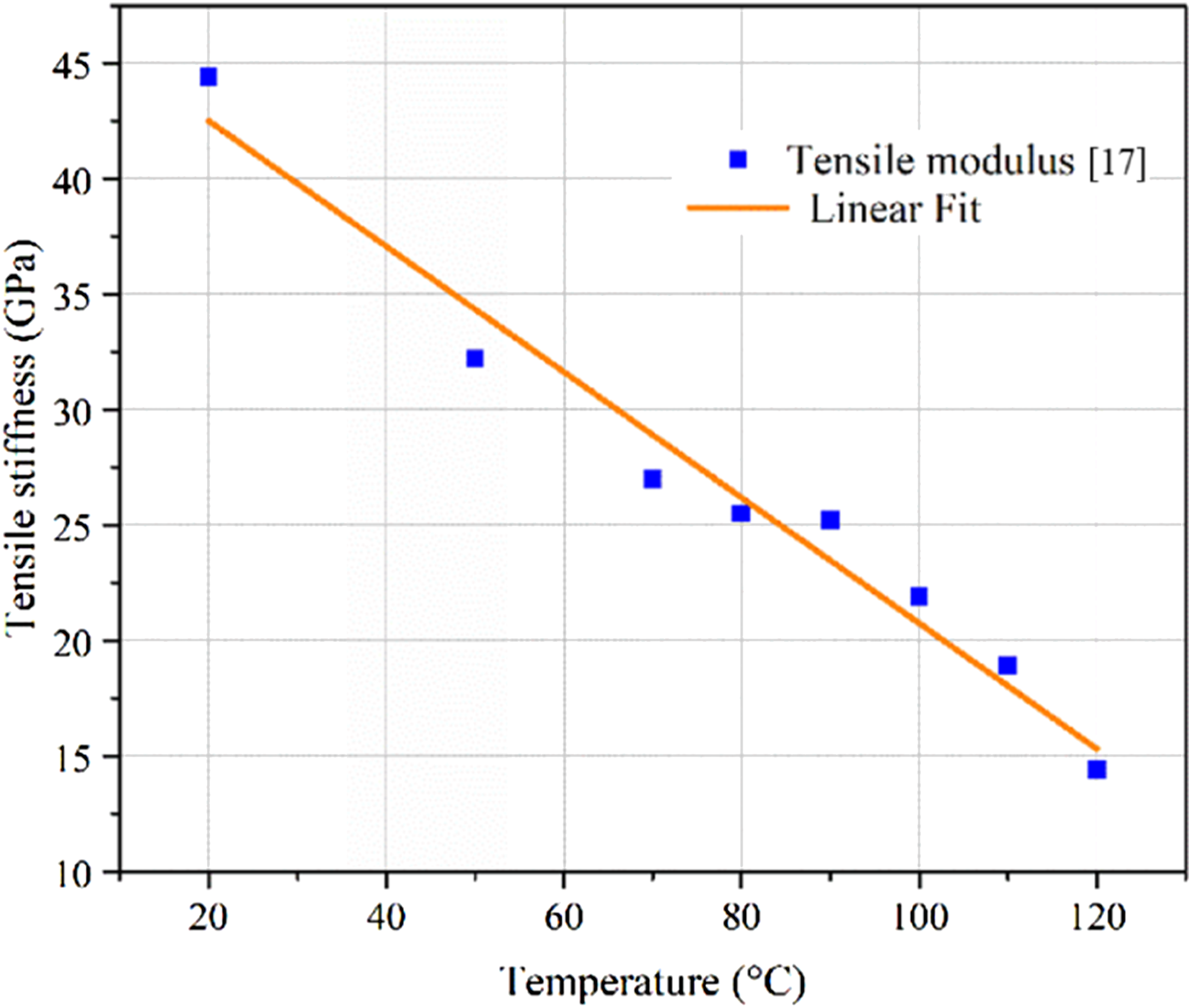
Out-of-plane bending behaviour
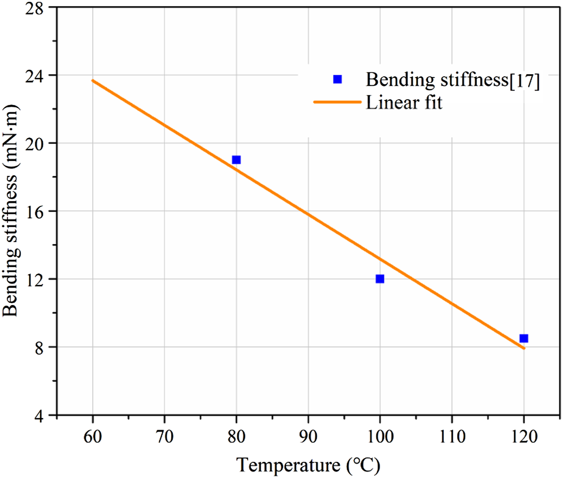
To obtain an accurate prediction of wrinkling in stimulation, the out-of-plane bending stiffness was fitted in the thermal dependency based on the experimental data obtained with different material temperatures in literature.
17
Considering the orthotropic lay-up ([0/90]2) composite laminate used in this research, the out-of-plane bending stiffness in the x- and y-directions were treated as identical. Considering the forming temperature of material, the out-of-plane bending stiffness values determined for the x- and y-directions at 80, 100, and 120°C were tested and the corresponding results are plotted in Figure 6, and the linear fitted result is expressed as follows Linear fit of thermal-dependent bending stiffness under various temperatures.
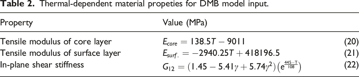
Material properties for DMB model
Thermal-dependent material propeties for DMB model input.
Thermal properties of materials

Set-up of the hemisphere part forming model
For the thermo-stamping simulation modelling with a hemisphere part, the geometry and dimensions of the forming setup and blank are illustrated in Figure 7, similar to previous experimental studies.17,29 The punching tool, holding die, and blank holder were modelled by a 3-D coupled temperature-displacement solid element (C3D4RT) with rigid constraints. A pressure of 2.9 kPa was applied on the surface of the blank holder to simulate the boundary constraint of the holder. The punching tool moved at a constant speed of 6.35 mm/min and a vertical displacement of 120 mm was defined. For the blank with the biaxial [0/90]2 lay-up laminate with a thickness of 0.150 mm thickness, a 4-node coupled temperature-displacement shell element (S4RT) was adopted, and the element size was meshed as 2 mm Geometry and dimensions of the simulation model.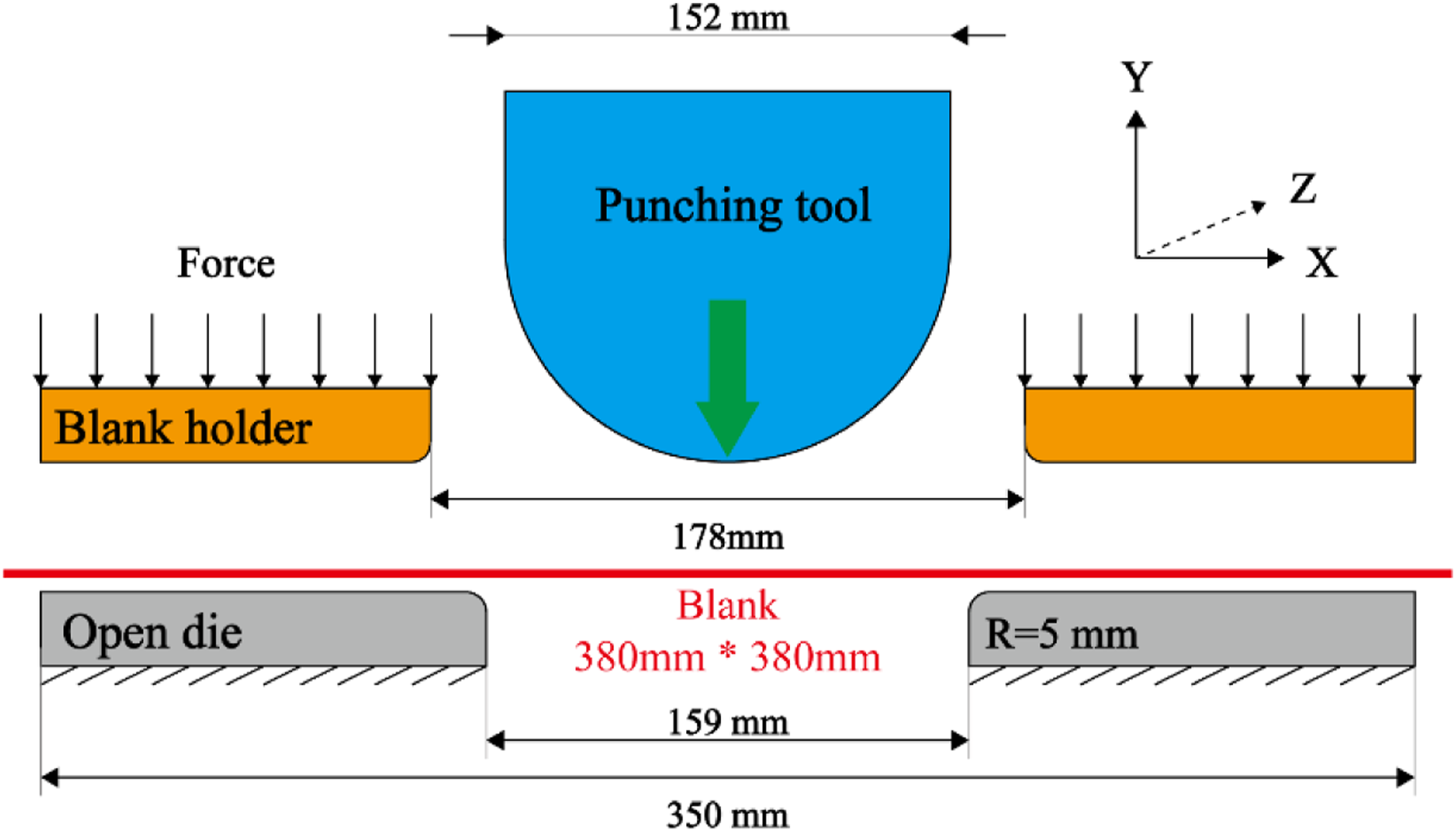
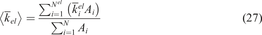
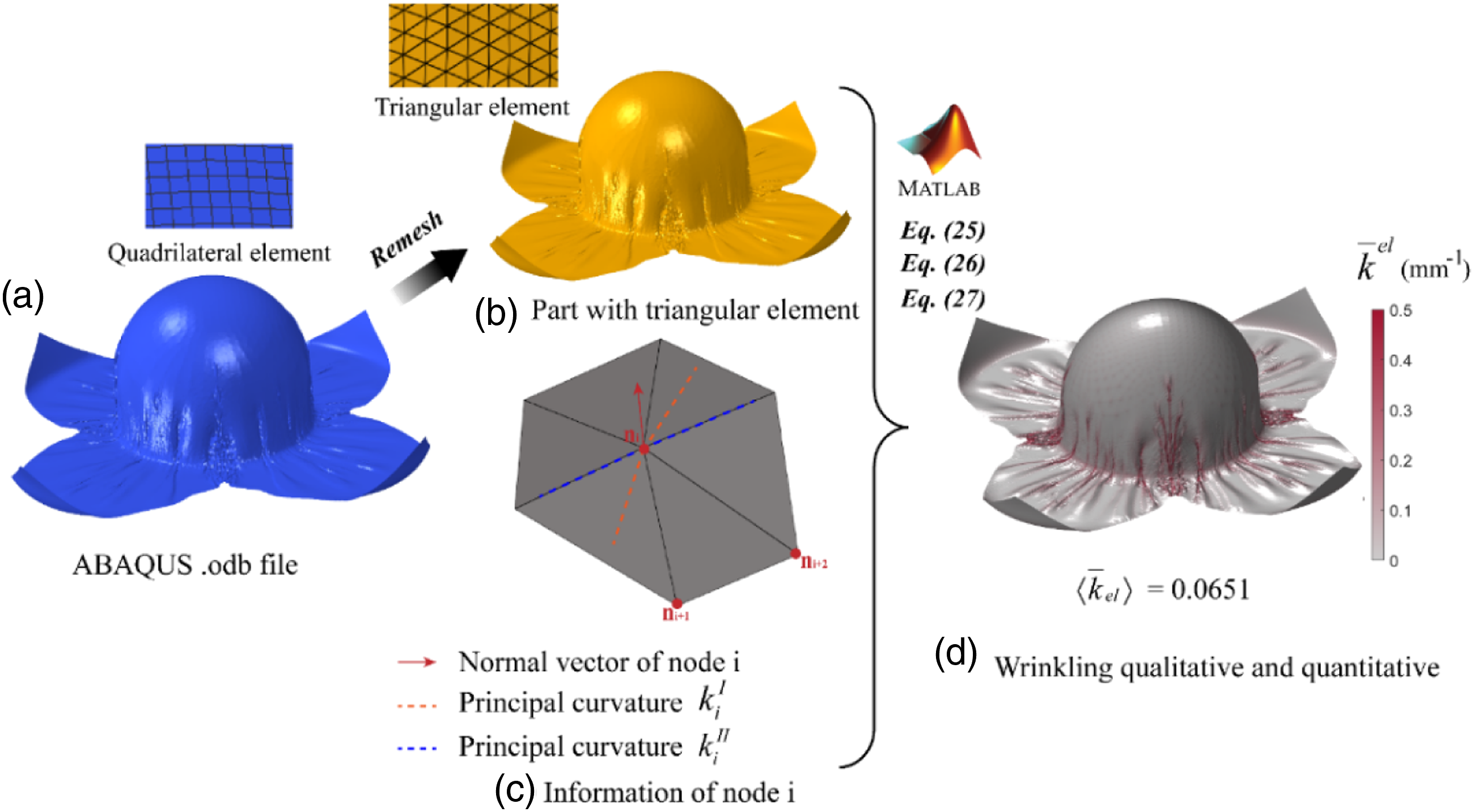
Wrinkling qualitative and quantitative assessment approaches
The wrinkling intensity is widely used as a critical factor for assessing the forming quality of the final CoFRTP part, and different qualification methods have been proposed.3,30 A favourable method for the wrinkling quantification of three-dimensional CoFRTP parts was provided by Dörr et al.,
30
which is based on the modified mean curvature estimation method using a triangular mesh surface.
3
A similar method was adopted in this study with some modifications. In this study, each 4-node element in forming result is split in half and get two 3-node elements with assist of Hypermesh software. The nodal modified mean curvature at node i ( Schematic of the qualitative and quantitative assessment of the wrinkling of the CFRTP part.

Model validation and application
Model validation
In order to verify the accuracy of the constitutive equation and the numerical method provided above, the picture frame test, cantilever bending test and the classical hemisphere-forming process are performed and compared in this section. Considering the length of the article, the picture frame test simulation results are illustrated in Figure S2 and Figure S3.
Cantilever bending simulation and validation
To validate the DMB method introduced in Section 2, simulations of vertical cantilever out-of-plane bending tests were performed at 80, 100, and 120°C. The numerical simulations were performed under identical testing conditions, and the simulation results were compared with the experimental results. For the out-of-plane bending test, as shown in Figure 9(a), the vertical cantilever test protocol followed procedures described in literature.
34
A rectangular laminate strip with a gauge length of 250 mm and a width of 20 mm was clamped vertically on the testing fixture. The transverse force is then applied to the tip of the strip with a 50 mm displacement of the tip deflection to achieve the testing objectives. The radiation provided by concentrated ceramic infrared (IR) from one side of sample could ensure that the samples had the required temperature distributions at different temperature levels. Each test is performed at constant temperature. The experimental temperature conditions and corresponding modelling conditions for the numerical simulations are listed in Table 4. For the simulations using the DMB model, the modelling conditions were identical to those used in the experiment. The Ecore and Esurf. were obtained according to equation Ex-direction= Ey-direction.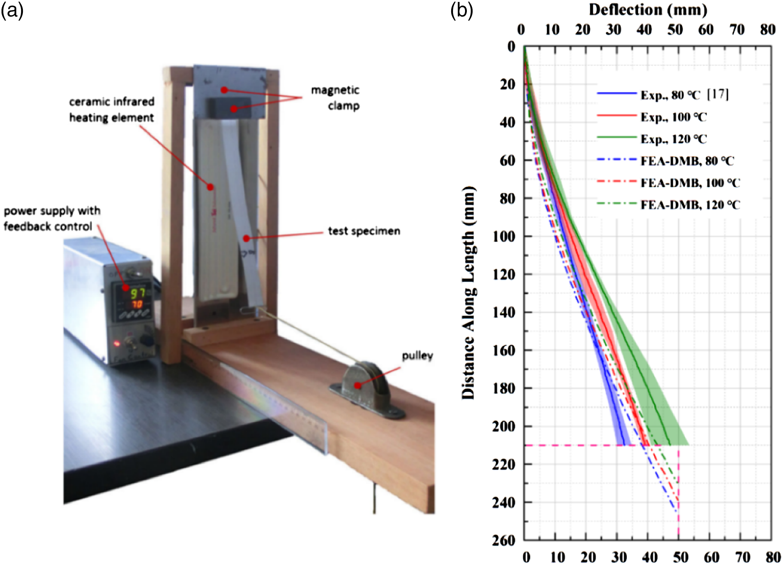
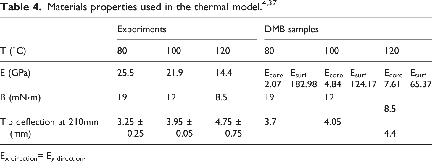
The numerical simulation results were compared with the experimental results, as shown in Figure 9(b). Corresponding experimental results are supplied by literature. 17 Compared to the experimental results, it can be found that the simulation-predicted tip deflections at a 210 mm distance along the length of the DMB samples at 100 and 120°C testing conditions were located within the corresponding error band. However, the simulation-predicted value for the sample with 80°C testing condition and experimental result is slightly different, however the difference is less than 0.45 mm. For the global edge profile of the deformed samples, the M–κ curves from the experiments and DMB method simulations agree well, even though slightly different gradients can be observed at the beginning of the curves. Accounting for the inevitable experimental error, for example, the difficulty in controlling the uniform and stable temperature distribution of the samples, the simulation results of the DMB method are considered acceptable.
Thermo-stamping forming simulation and validation
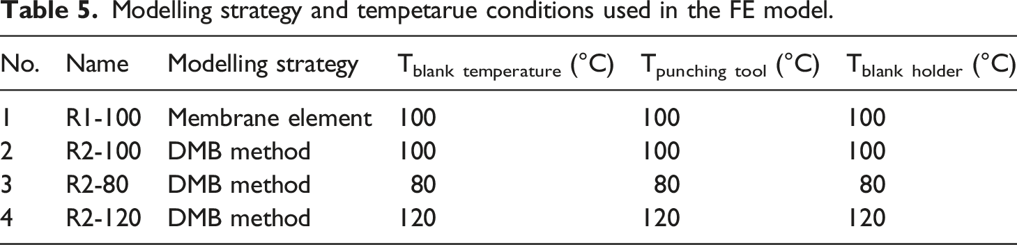
Modelling strategy and tempetarue conditions used in the FE model.
The hemisphere-forming experimental results with the same forming conditions as R2-100 are shown in Figure 10(a). The numerical simulation results with the traditional membrane-element approach, without considering the bending stiffness, are also presented in Figure 10(b) for comparison. It can be observed that there are significant differences between the simulation results of the traditional membrane element approach and the experimental results. A comparison of the numerical simulation results with the DMB method proposed in this paper and the experimental results in Figure 10(a) and (c), respectively, further confirmed the importance of the bending stiffness. It can be observed that the simulation results with the DMB method are relatively similar to the experimental results with large irregular wrinkle patterns generated on the surface around the bottom periphery of the dome, and a number of small wrinkles occurred on the dome surface near the bottom periphery of the doom. Some minor notable differences between the simulation and experimental results could be attributed to the linear relationship between the bending stiffness and blank temperature. In addition, the rate-dependency of out-of-plane bending stiffness as another possible origin for deviation.1,8 Previous work has shown that the linear relationship is less accurate than the nonlinear relationship.10,13 Comparison of the results of (a) experimental result,
17
(b), (c) forming simulation surface profile, and (d)–(f) wrinkling intensity of components.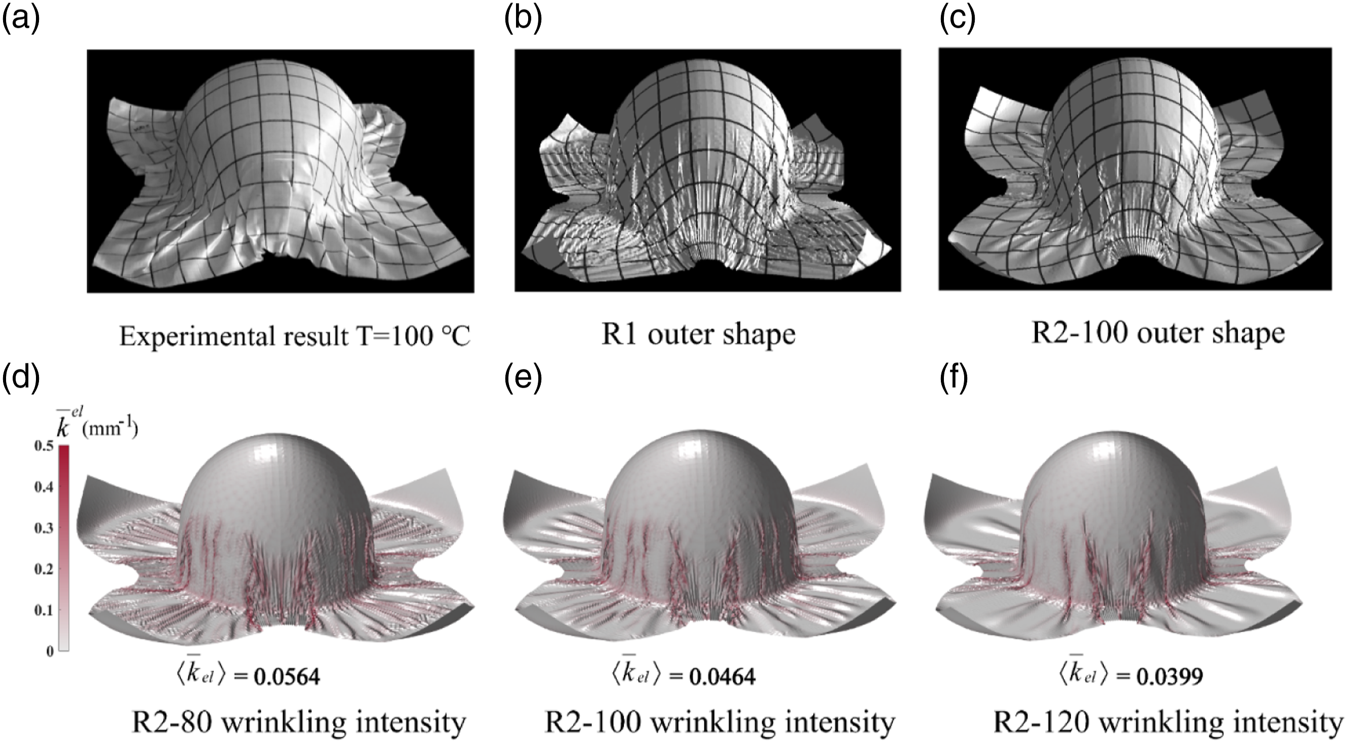
Two more forming processes with different forming temperature conditions, R2-80 and R2-100, as listed in Table 5, were carried out to validate the accuracy of the numerical model-based DMB method. The influence of the forming conditions (i.e. decreasing or increasing the forming setup temperatures) on the final quality of the CoFRTP components is also illustrated by comparing the results in Figure 10(d) to (f). It can be observed that the wrinkle intensity decreases with increasing setup forming temperature, which exhibits a similar trend reported in literature.15,35
Application of temperature-dependent forming simulation for process optimization
It was demonstrated in the previous section that the selection of the forming parameters, such as temperature, in the initial set-ups is critical for the quality of the final CoFRTP component, such as the wrinkling intensity.12,19 Owing to the high productive efficiency requirement of the thermo-stamping process in industrial applications, the initial temperatures such as the Tpunching tool and Tblank holder are usually defined as lower than Tblank. Consequently, the optimisation of these parameters is important for achieving the best balance between the quality of the component and the production efficiency.
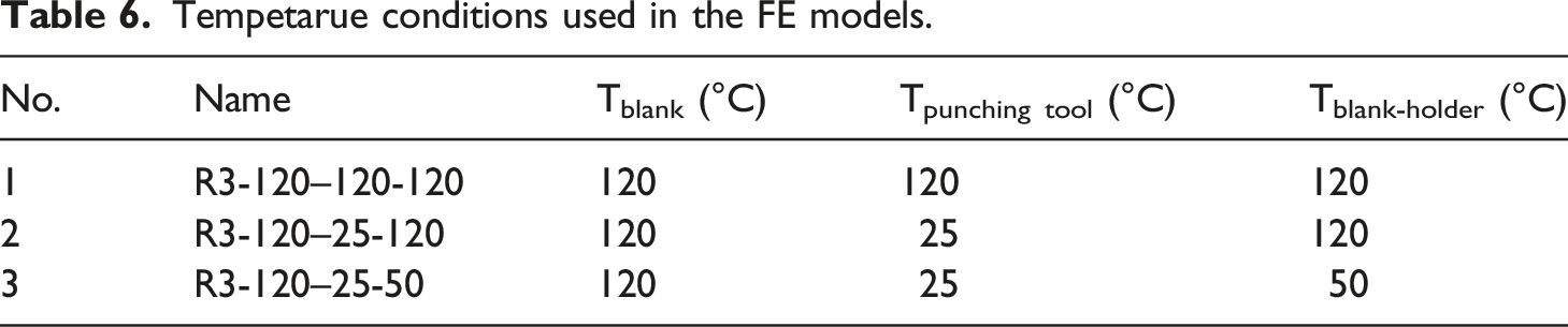
Tempetarue conditions used in the FE models.
Influence of forming parameter Tpunching tool
In the thermo-stamping forming industrial application, heating up the punching tool normally requires more energy and longer time owing to its large size. Consequently, it is desirable to understand the influence of the forming parameters of the Tpunching tool in process optimisation. The temperature-dependent forming simulation results for the thermo-stamping forming process with different Tpunching tool of 120 and 25°C and identical process parameters, for example, R3-120–120-120 and R3-120–25-120, are presented in Figure 11(a) and (b), respectively. It is observed that the overall deformation features, such as the outer shape, in-plane shear angle, and wrinkling intensity and distribution, are similar for the two simulations. The quality of the final CoFRTP component in terms of the quantitative assessment parameters of the in-plane shear angle and wrinkling intensity exhibited insignificant changes. Influence of Tpunching tool on the in-plane shear angle and wrinkling intensity of CFRTP parts.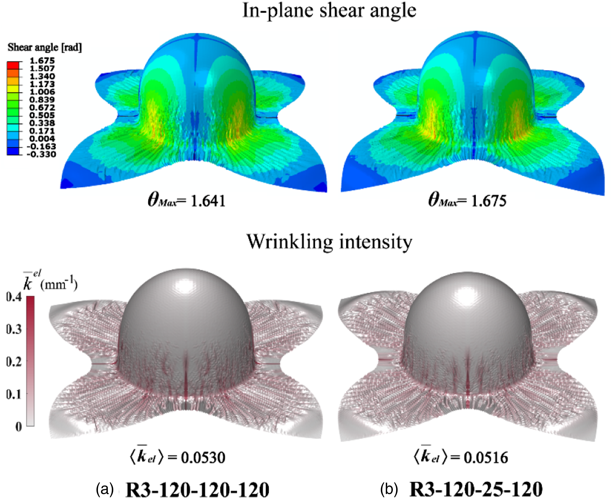
The influence of the initial forming parameter Tpunching tool on the temperature redistribution of the composite laminate blank at different forming stages is illustrated in Figure 12. It can be observed that there is a relatively larger temperature redistribution for the R3-120–25-120 forming process with a lower initial Tpunching tool of 25°C compared with the forming process with a higher initial temperature of 120°C. Because the yarns of the composite laminate blank at the top dome location are almost not subjected to shearing deformation, the temperature redistribution at the top dome location has very little influence on the final quality of the CoFRTP in terms of the in-plane shear angle and wrinkles at these locations. Furthermore, there is also no significant influence on the wrinkling generated around the bottom periphery of the dome because the composite material had already deformed before the relatively small temperature change in these areas. Influence of Tpunching tool on the blank temperature distribution during forming.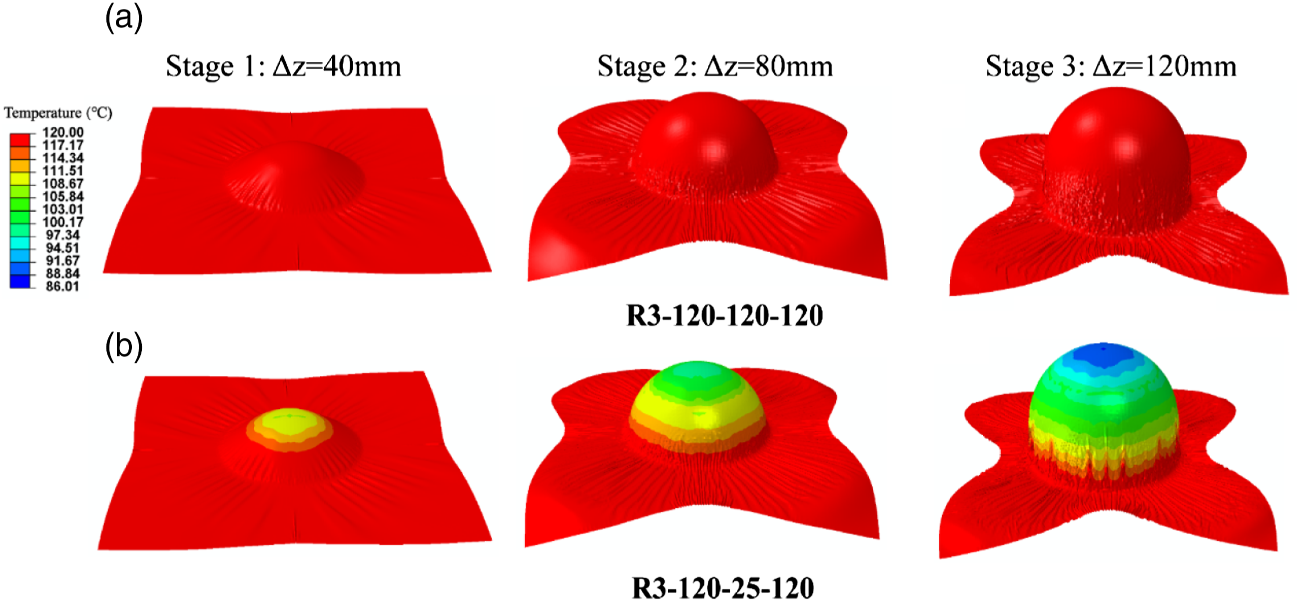
Influence of forming parameter of Tblank holder
In addition to the temperature of the Tpunching tool, the temperature of the Tblank holder in the setup of the thermo-stamping forming is also an important parameter that influences the forming process and the final quality of the CoFRTP parts. The effect of the Tblank holder is illustrated by comparing the simulation results shown in Figure 13. In the two simulations, the temperatures of Tblank (120°C) and the Tpunching tool (25°C) are the same, and the temperature of the Tblank holder is reduced from 120 to 50°C. The quality of the final CoFRTP component in terms of the quantitative assessment parameters of the in-plane shear angle and wrinkling intensity exhibited considerable differences. The θ
max
changed from 1.675 to 1.527, which was a reduction of approximately 10%. Meanwhile, the wrinkling intensity parameter Influence of Tblank holder on the in-plane shear angle and wrinkling intensity of CFRTP parts.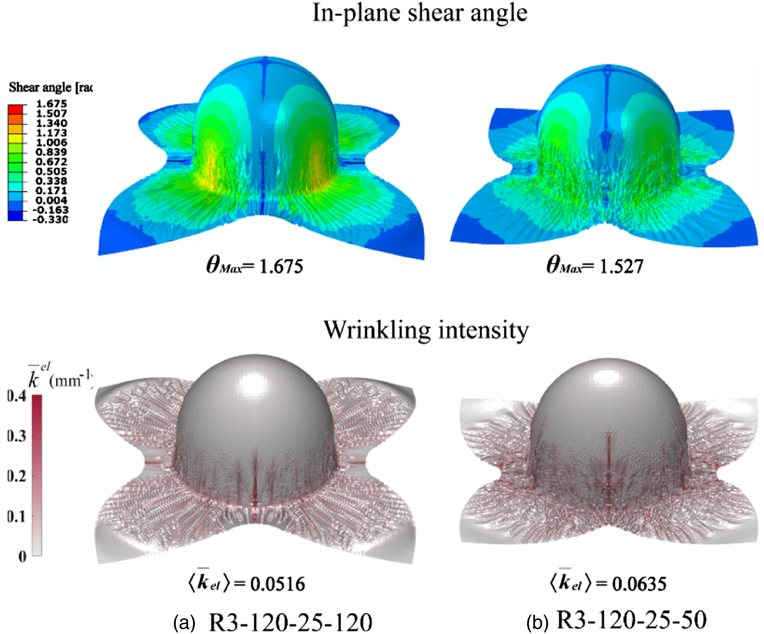
The substantial influence of the temperature Tblank holder on the quality of the final CoFRTP component can be attributed to the changes in the forming parameters, particularly the temperature redistribution within the blank and the associated temperature-dependent material deformation behaviours. The temperature redistributions during the thermo-stamping forming process with a Tblank holder at 25 and 120°C are compared in Figure 14. It can be observed that the lower temperature around the bottom of the periphery of the dome caused by the temperature redistribution of the blank holder occurred even before the punching tool contacted the blank. Consequently, the lower blank temperature led to a higher shear stiffness and smaller shear angle, as shown in Figure 13, where θ
max
reduced to 1.527 for the Tblank holder at 50°C from 1.675 for the Tblank holder at 120°C. The corresponding wrinkling intensity parameter Influence of Tblank holder on the blank temperature distribution during forming.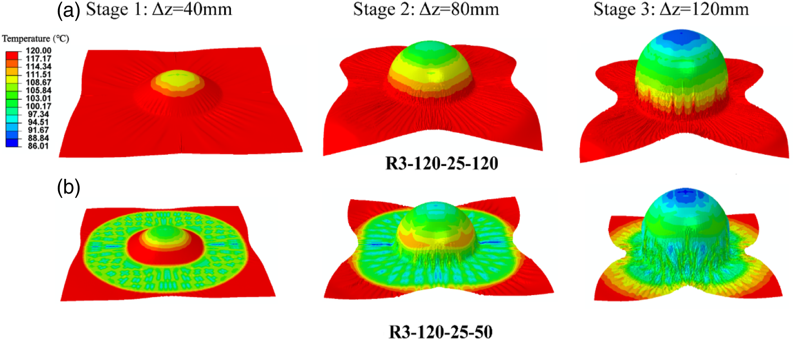
Overall influence of forming parameters Tpunching tool and Tblank holder
The forming simulation results presented in the previous sections indicate that the influence of the forming parameters Tpunching tool and Tblank holder on the quality of the final CoFRTP components is attributed to progressive changes over the entire forming process. As an example, the evolution of the critical quality assessment parameter of the wrinkling intensity Comparison of evolution of the wrinkling intensity paramters during forming.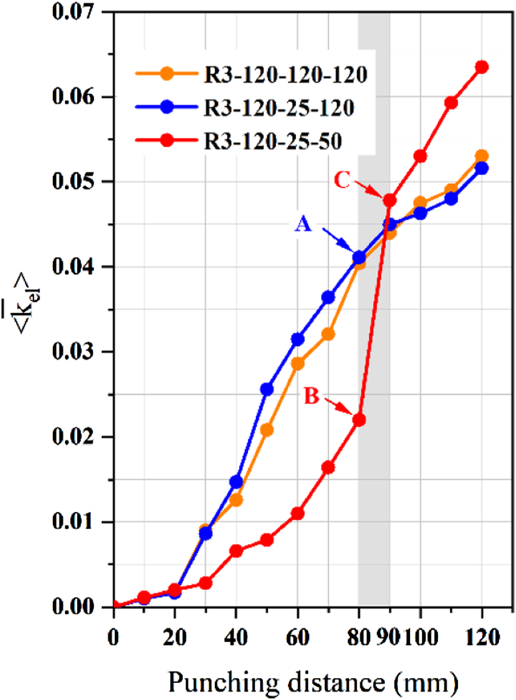
Figure 16 presents the critical forming parameters including temperature distribution, in-plane shear angle and wrinkling intensity at the key stages A, B and C during the forming process illustrated in Figure 16. Evidently, the wrinkling intensity parameter at the same stage for R3-120–25-50 is only about 50% compared with that of R3-120–25-120 shown in Figure 16(c). This could be attributed to the lower temperature at the surrounding area of the dome caused by the temperature redistribution within the high temperature composite blank contacted with the low temperature blank holder, as shown in Figure 16(a). The reduced temperature in the blank surrounding the dome and around the bottom periphery of the dome enhanced the shear stiffness and then reduced the shear angle in the blank, as shown in Figure 16(b). The lower shear angle restricted the onset of the wrinkling at the early stage of material properties changes. Furthermore, the improved local out-of-plane bending stiffness of the blank, induced by the lower temperature, could also decrease the development of wrinkles.
35
When the punching tool distance is increased from 80 to 90 mm, the wrinkling intensity parameter at stage C during the forming process R3-120–25-50 is more than double from 0.0220 to 0.0478. This is because the further reduced temperature at the contact area, the enhanced shear stiffness in the surrounding blank and the increased local out-of-plane bending stiffness in the contact area together increased the hardness of the blank material. The deformation of the harder blank material is more difficult and consequently leads to the rapid generation of the wrinkles within the CoFRTP parts. Comparison of critical forming paramters: (a) temperature distribution, (b) in-plane shear angle, and (c) wrinkling intensity.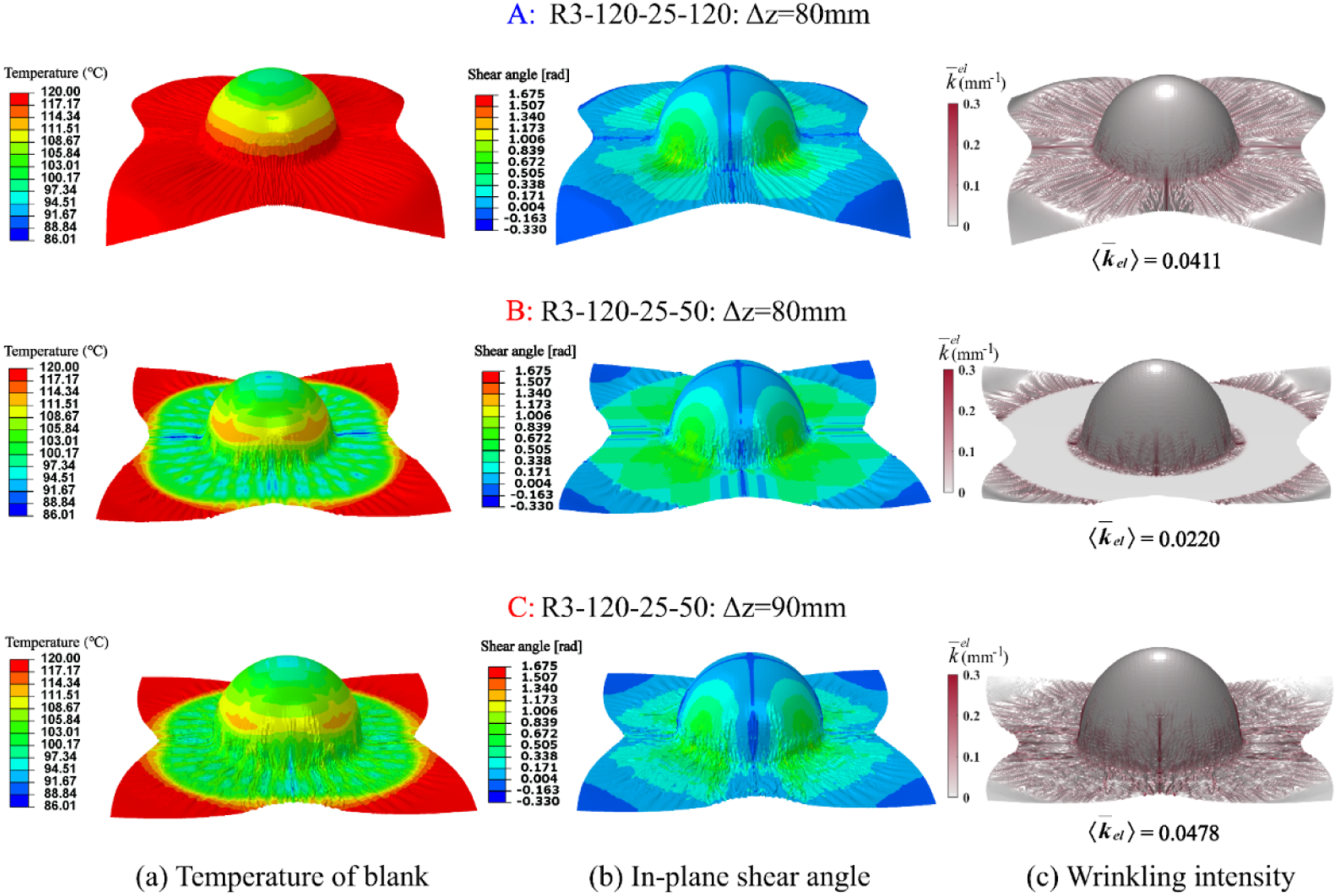
The thermally dependent responses and deformation mechanism investigations performed with numerical simulations in this work could potentially provide good guidance for setting the initial forming parameters such as the Tpunching tool and Tblank holder in actual thermo-stamping forming manufacturing. For instance, because the simulation results demonstrated that the reduction of the Tpunching tool in the setup has an insignificant influence on the final quality of the CoFRTP parts, the punching tool temperature could be reduced to reduce the heating and cooling time and improve the production efficiency. Nonetheless, other factors, such as the phase transition of the composite blank, which is not included in this work, should also be considered in the selection of the Tpunching tool. The simulation results clearly indicate that the wrinkling intensity is more sensitive to the Tblank holder, and it is suggested that this temperature should be kept as close as the Tblank in thermo-stamping manufacturing process.
Conclusion
In this study, the temperature-dependent deformation characteristics that occur during the thermo-stamping process were described by a set of constitutive models via the decoupling of the in-plane membrane and the out-of-plane bending behaviours. The in-plane tensional modulus was modelled as non-isothermal owing to the relatively low melting point of the UHMWPE fibre, whereas the in-plane shear stiffness was described nonlinearly using a hypoelastic constitutive model that accounted for both rate- and temperature-dependency. The out-of-plane bending behaviour is considered using the DMB method, with three overlapping layers of shells based on laminate theory. Moreover, a nodal modified mean curvature and an estimation method was introduced for the qualitative and quantitative assessment of the wrinkling intensity in the final formed parts to facilitate quality optimisation.
A validated numerical simulation strategy was used to investigate the influence of various temperature conditions of the forming process and the underlying mechanisms on the final quality of the formed thermoplastic parts. The simulation results indicate that increasing the blank temperature results in a reduction in the wrinkling intensity and improvement in the forming quality. Furthermore, the temperature of the blank holder affected the wrinkling intensity and forming quality more significantly than the temperature variation of the punching tool. Nonetheless, the proposed model has some limitations such as the rate-dependency of the out-of-plane bending stiffness and the phase change of TPU is not considered, since the whole stamping stage is fast and the resin remains in molten state.
Owing to the high production efficiency requirement of the thermo-stamping process in industrial applications, optimisation of the temperature parameters is crucial to achieve the best balance between component quality and production efficiency. Therefore, the current study, with further development, could potentially facilitate the optimisation of the thermo-stamping process.
Supplemental Material
Supplemental Material - Temperature-Dependent modelling of tension, in-Plane shear, and bending behaviour in non-isothermal thermo-Stamping process simulation of unidirectional UHMWPE fibre reinforced thermoplastic TPU composites
Supplemental Material for Temperature-Dependent modelling of tension, in-Plane shear, and bending behaviour in non-isothermal thermo-Stamping process simulation of unidirectional UHMWPE fibre reinforced thermoplastic TPU composites by Hongda Chen, Jihui Wang, David Colin, Shuxin Li and Klaus Drechsler in Journal of Thermoplastic Composite Materials
Footnotes
Acknowledgements
The authors acknowledge the support of LCC, TUM, Germany, and Wuhan University of Technology, China, in the development of the numerical model.
Declaration of conflicting interests
The author(s) declared no potential conflicts of interest with respect to the research, authorship, and/or publication of this article.
Funding
The author(s) received no financial support for the research, authorship, and/or publication of this article.
Supplemental Material
Supplemental material for this article is available online.
References
Supplementary Material
Please find the following supplemental material available below.
For Open Access articles published under a Creative Commons License, all supplemental material carries the same license as the article it is associated with.
For non-Open Access articles published, all supplemental material carries a non-exclusive license, and permission requests for re-use of supplemental material or any part of supplemental material shall be sent directly to the copyright owner as specified in the copyright notice associated with the article.