
Abstract
The purpose of this work is to evaluate the reconsolidation of a carbon fiber composite with poly (aryl ether ketone) (PAEK)/carbon fiber laminates after suffering impacts from different energy levels (5, 10 and 30 J) and being restored by reconsolidation. For this comparison, thermal analysis, and compression after impact tests were performed to evaluate the properties of the material before and after the reconsolidation process. According to the found results, it was observed that with small damages it is possible to fully recover the material after new consolidation and for larger damages there is also a partial recovery compared to the base laminate. The material remains thermally stable in all situations, in other words, its thermal properties remain even after impact tests and reconsolidation process.
Introduction
Polymeric composites stand out for their high specific mechanical performance, the possibility of manufacturing components with complex geometries, corrosion resistance, among others.1–4 These characteristics make it attractive to both academia and industry, especially the aircraft industry. 3 Currently, two leading companies in the aircraft manufacturing sector, Boeing and Airbus, have launched the 787 and A350 aircraft, respectively, approximately composed by 50% in volume of composite materials, proving the relevance of this material to the aircraft manufacture.
Although the thermoset matrices are usually used in the composite manufacture,5–7 the thermoplastic matrix have gained prominence in the market for offering advantages such as ease of manufacture, high tolerance to damage and impact, high working temperatures, less complex processing cycles,
The PAEK matrix used in this work is characterized by high stability at high temperatures and high mechanical resistance, whose chemical structure is composed of ketone (R-C=O-R) and ether (R-O-R) groups, with the aryl group responsible for the R bond between the functional groups. This polymer presents a glass transition temperature of approximately 157°C and a melting temperature of 305°C, however, the ratio and sequence of ether and ketone groups affects the melting and glass transition temperature, heat resistance and processing temperature.13–15
Repairability is an important feature that is favored by the ability of thermoplastics to soften and flow when subjected to increases in temperature and pressure, and solidify when cooled, in a reversible physical transformation. This capacity is due to the molecular structure of the thermoplastics, which comprises chemically independent macromolecules, so that the polymer chains are mostly connected by intermolecular interactions or van der Waals forces, forming linear or branched structures.16–18
An aircraft since its manufacture, assembly and even its service life is exposed to suffer different damages caused by impact loads such as bird impact, tool drops, hail, among others. The impact loads can be distinguished in high-velocity impact (HVI), low-velocity impact (LVI) and ballistic impact (BI). All types of impact loads cause damages that negatively affect the mechanical properties of the component. The low-velocity impact, which corresponds to the drop of a weight with a mass of around 5–10 kg from a few meters, is considered one of the most dangerous as it generates imperceptible damage making it difficult to identify it in a short period of time, usually called Barely Visible Impact Damage (BVID) [18]. The impact on carbon fiber reinforced polymer laminates causes a combination of different types of damage, such as fiber breakage, matrix cracking, delamination, and debonding, resulting in complex failure mechanisms that depend on the energy level involved in the impact test.19–21
Compression after impact (CAI) is a method normally used to evaluate the structural health allowing to measure the residual compression strength of a specimen submitted to the LVI.22–24 These tests occur in two steps: first, a transverse low-velocity impact is applied to a specimen which will be capable of producing internal damage and, subsequently, the in-plane compression of this impacted laminate is evaluated to determine its residual strength. 25 Compressive strength reduces after an impact, so when the compression mechanisms interact with an induced impact the damage propagates generating the failure at significantly low load levels when compared to a laminate without impact damage. 26 Therefore, understand the energy absorption mechanism during impact event is important to design properly a structural aeronautical component. 27
Xu et al. 28 observed that CAI strength value for poly (ether ketone) with phenolphthalein group (PEK-C) carbon fiber composites was approximately 184.5 MPa and the laminate presented a damage area of 1164 mm2 with delamination being the main damage mechanism associated with fiber fractures. The incorporation of PEK-C interleaved panel improved CAI properties by 14% and reduced the damage area to 1101 mm2. The addition of 5,0 and 10,0 wt% of multiwalled carbon nanotubes (MWCNT) in PEK-C improved the compression after impact properties by about 25 and 33% compared to the base laminate and reduced the damage area of the laminates to 918 and 826 mm2, respectively.
Tuo et al. 26 evaluated epoxy/carbon fiber composites related to their impact behavior under four impact levels (4, 6, 10, and 15J). As demonstrated by the authors, delamination is one of the main damage modes, which was studied by experimental testing and numerical simulation. Damage associated with delamination was found at locations around the impact indentations as an irregular circle under low impact energy (4 and 6 J). Also, only delamination occurred in low impact energy levels with delamination area increasing from 210 to 310 mm2. As the impact energy increased, the delamination area increased, changing the damage shapes gradually from an irregular circle to an irregular ellipse. This change can be noted in the damage mechanism as well, revealing delamination and matrix crack for moderate impact energy levels (10 J), whereas severe delamination, matrix crack and fiber damage occurred for high impact energy level (15J).
CAI properties for PEEK/carbon fiber/glass fiber hybrid laminates were studied by Dubary et al. 29 in two different temperature conditions, at room temperature (20°C) and at a temperature slightly higher than glass transition temperature (150°C) of the composite. For both temperatures evaluated, the impact energy ranged from 20 J to 40 J by increments of 5 J. The authors concluded that the compressive failure strength is about 300 MPa, which was like the non-impacted laminates, and the temperature does not influence this property. The toughness of the matrix is improved close to glass transition temperature (Tg), contributing to reduce the impact-induced delamination and, consequently, slows down the spread of impact-induced damage (intra- and inter-laminar cracks). Macroscopically it is observed that the failure is mainly induced by the global buckling, resulting from a significant permanent indentation, even for high impact energies.
Over the last two decades thermoplastic polymer composites have been paid great attention as a structural component for aerospace, automotive and industrial applications. 1 As mentioned previously in this work, thermoplastic composites present some advantages in comparison to thermosets laminates related to reconsolidation, repairability, and recyclability due to their meltable nature. Even though thermoplastic composites have potential for material reconsolidation and repairability, applications for these laminates have been missing. Therefore, its urgent to study the mechanisms associated with reconsolidation process and repairability to have a better understanding of the “new” properties of the composite. Also, it is worth noting that thermoplastic composites are increasingly applied when high performance is required, so it is essential not only understand their potential for hot compression reconsolidation after being damaged by impact, but also their post-repair ability to withstand mechanical loads.30,31 The aim of this work is to investigate the thermal, impact and compression after impact properties of PAEK/carbon fiber composites. The main contribution of this work is to evaluate the influence of laminate reconsolidation on the properties mentioned and contribute to the literature, since few works study involving CAI and the influence of reconsolidation in high-performance engineering thermoplastics properties are related by the literature
Experimental procedure
Materials and sample preparation
Poly (aryl ether ketone) (PAEK)/carbon fiber semipreg (Toray Cetex® TC1225) was supplied by Toray Advanced Composites (Netherlands) with a fiber volume fraction of around 58% v/v. The laminates were consolidated by stacking 12 plies of semipreg, with a stack sequence of [(+45/-45)/(0/90)]3S. The laminates were consolidated in a hot-platen press following the processing cycle: First, the material was heated from room temperature up to 350°C under 0.2 MPa of pressure for 30 minutes to guarantee the temperature homogenization (Kapton® films were placed to bottom and upper surfaces of the plate to prevent the sticking of the composites). Subsequently, a pressure of 1 MPa was applied for 20 minutes to consolidate the laminate, and then a cooling step was performed at a rate of 5–10°C.min−1 to room temperature. Laminates with dimensions of (550 × 550 × 3.72) mm3 were prepared, impacted, and coded as PAEK/carbon fiber (PAEK/CF – material without any damage). A second plate which was also impacted was reconsolidated using the same processing cycle described above and no extra PEAK was added to the composite. The final reconsolidated laminates, coded as PAEK/CF-Re, showed dimensions of (550 × 550 × 3.10) mm3. It is worth noting that the variation in the laminate’s thickness is ascribed to the squeeze of the polymer matrix during the reconsolidation process.
In Figure 1 it is possible to observe the laminate after processing (left side) and after the impact test (right side), where it was cut into 100 mm wide strips and a total length of 550 mm - being possible to separate 3 regions for the impact, of 100 × 150 mm each. Laminate after processing (left side) and impact samples (right side).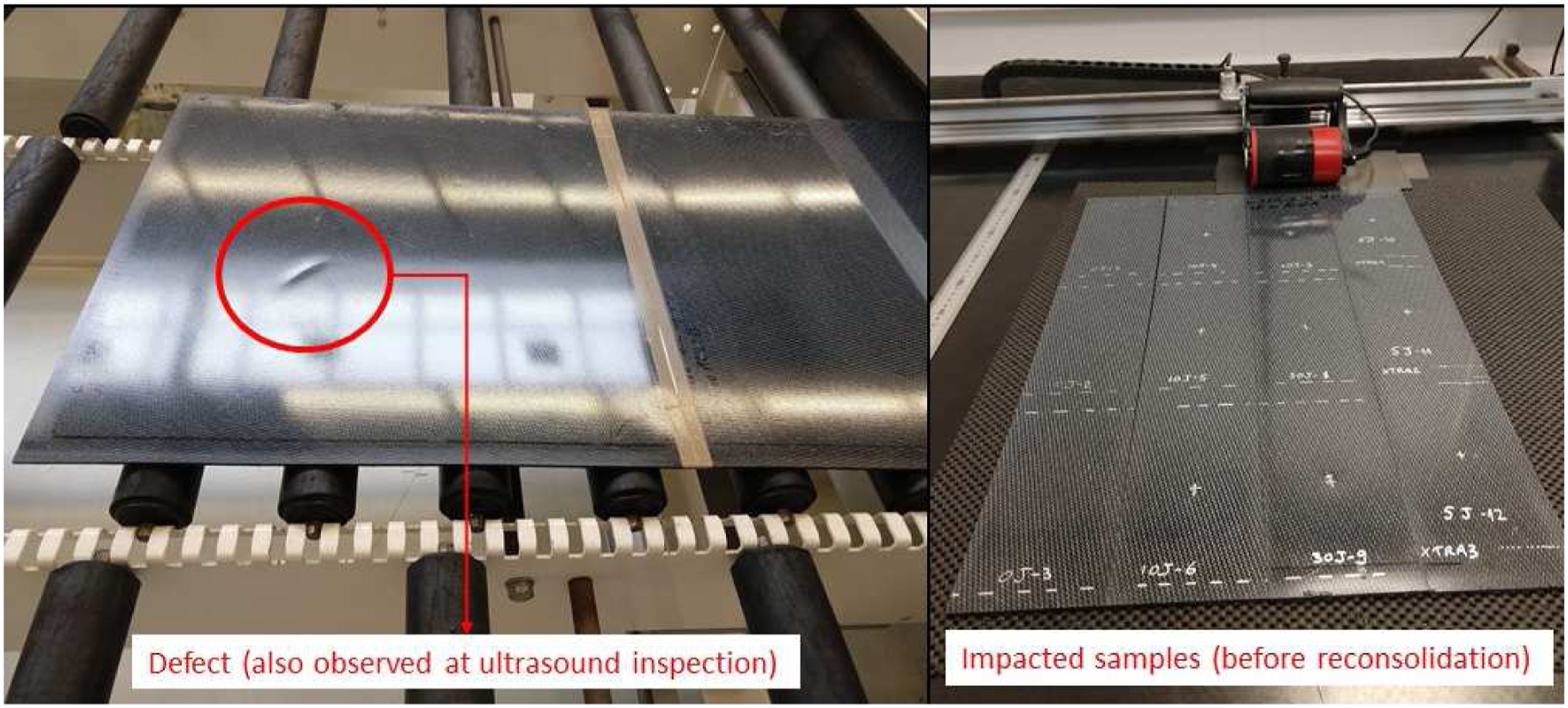
Experimental setup and procedure
Quality consolidation and damage evaluation of the laminates
C-scan analysis was performed to verify eventual defects induced during the processing step, such as internal voids, delamination, or rich resin regions, and to identify the damage after impact tests. The analysis was carried out in both laminates (PAEK/CF and PAEK/CF-Re) and for all samples submitted to the impact tests using a RapidScan 2 Automated available at Toray Advanced Composites. C-scan data were obtained using the pulse-eco method with a linear transducer of 5 MHz.
Low-velocity impact tests
Low-Velocity Impact (LVI) tests on both composites laminates (150 × 100 × 3.72 mm3 and 150 × 100 × 3.10 mm3) were performed according to ASTM D 7136.
32
The Dynatup 8250 Instrumented Falling Weight Impact Machine (IFWIM) is a component impact tester used. This machine is versatile, both in terms of capacity (low to high impact energy) as well as specimen geometry. An oscilloscope-based data acquisition system (IAF ImpactLogger) was used to monitor force and mass displacement. The mass ranges from 3 to 34 kg, the maximum speed is 13 m/s and the maximum impact energy is 600 J. For this case, 5 J, 10 J and 30 J were used, with a mass (5.9 kg) and a velocity (1.3 to 3.2 m/s) were configured to take these energies. Each test group contains three specimens to evaluate the natural dispersion of the collected data. In Figure 2 we can see the impact machine and where the sample is positioned, centralizing the region that will receive the impact. impact machine and positioned sample.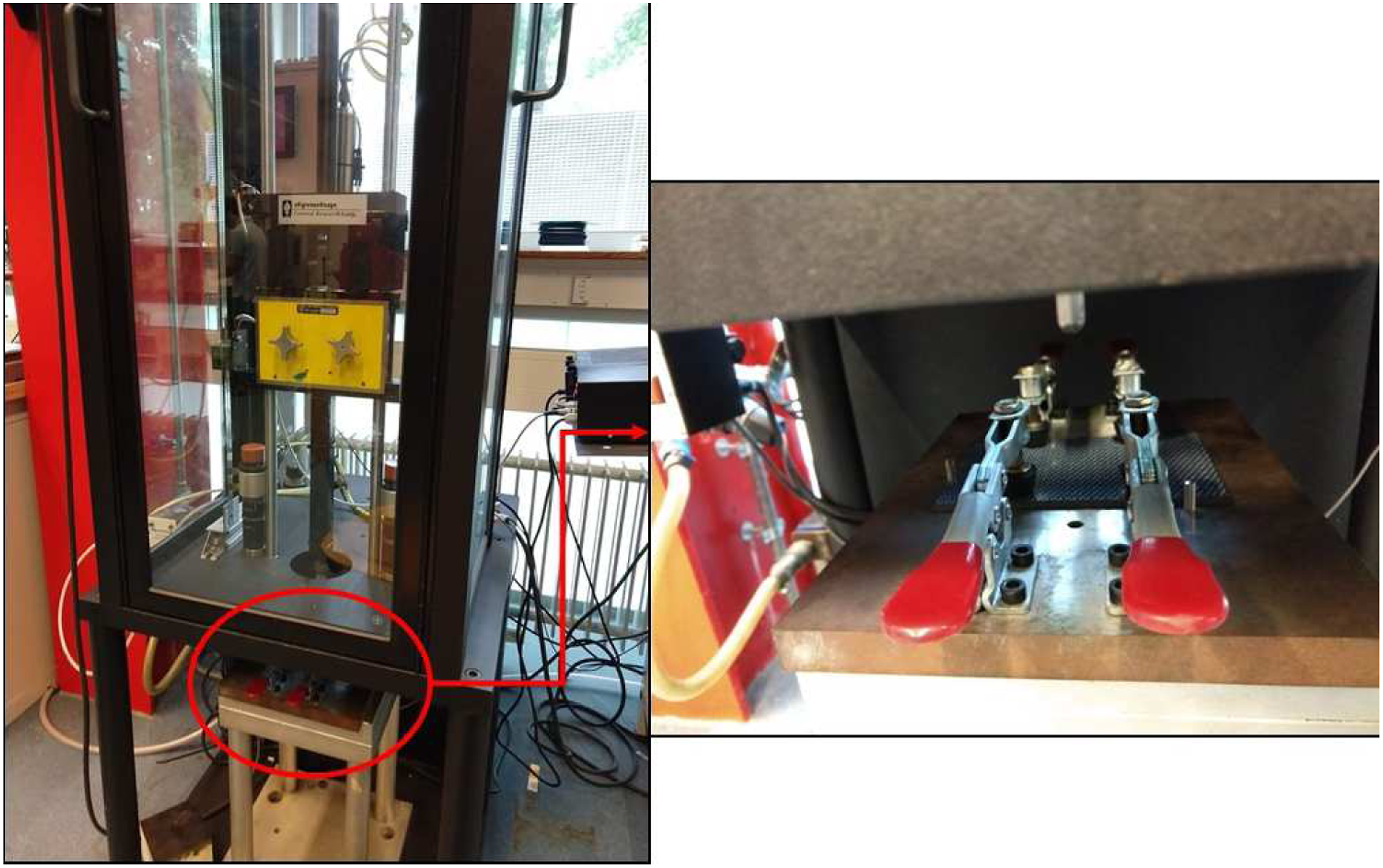
Compression after impact tests
Compression after impact (CAI) tests were carried out according to ASTM D 7137. 33 The tests were performed on Instron 5982 hydraulic machine, equipped with a load cell of 100 kN, and using a displacement rate of 1.25 mm.min−1. Three samples were used for each condition, in other words, for PAEK/CF and PAEK/CF-Re. It should be noted that the dimensions of the sample were adapted to carry out the test with the 100 kN load cell available. After the mechanical tests the fracture surface of the samples was analyzed using a stereoscope model Stem DV4 from Zeiss. No preparation was performed on the surface of the sample to avoid changes in the fracture aspects.
Thermogravimetric analysis
The thermal stability of the laminates was studied using SII Nanotechnology – Seiko TGA/DTA 6200 equipment at a heating rate of 10°C.min−1 over a temperature range of 25°C to 1000°C. The tests were performed under a nitrogen atmosphere (100 mL.min−1) on samples with a mass of approximately 10 mg in a platinum sample holder and alumina as reference material.
Differential Scanning Calorimetry
The crystallization behavior of the laminates was evaluated via Differential Scanning Calorimetry (DSC). DSC experiments were performed in TA Instruments Q20 equipment under nitrogen flow (40 mL.min−1) to prevent the oxidation of the samples. The tests were performed in dual scan mode (heat-cool-heat method), using a mass of ∼10 mg that was initially heated and cooled from 0°C to 400°C. Then, the sample was heated once more at a heating rate of 10°C.min−1 up to 400°C. Based on the data obtained from DSC, the crystallinity level was calculated according to:

X c is the degree of crystallinity of the material.
ΔH c is the melting enthalpy obtained from the peak melting area.
ΔH ° m is the melting enthalpy for 100% crystalline PEEK. This value was assumed to be 130 J/g according to Doumeng and collaborators. 34 It is worth mentioning that ΔH ° m data for PAEK was not found in the literature. For this reason, PEEK information was used in this work once both polymers show similar structure.
x is the volumetric content of fibers.
Dynamic-mechanical analysis
The viscoelastic properties were studied through dynamic-mechanical analysis (DMA) using SII Nanotechnology - Seiko DMS 6100 equipment. The analysis was performed in dual cantilever mode over a temperature range of 25°C-250°C, with a heating rate of 3°C.min−1, under a nitrogen flow of 100 mL.min−1, an oscillation amplitude of 10 µm, frequency of 1 Hz, and samples with dimensions of (55 × 10 × 3) mm3. The thermal expansion coefficient (CTE) was obtained from the thermomechanical analysis (TMA - SII Nanotechnology - SEIKO TMA/SS 6100). The temperature range was 25°C to 250°C with a heating rate of 3°C.min−1, nitrogen atmosphere (100 mL.min−1), and samples with dimensions of (10 × 10 × 3) mm3 were used.
Results and discussion
Thermal properties
TGA results before and after reconsolidation of the composites are shown in Figure 3. As can be seen, at least two stages of decomposition are observed in TGA curves. In the first stage of degradation, a rapid and significant loss of weight occurs around 500°C - 680°C, associated with random chain scission of the ether and ketone bonds. According to the literature,35,36 this is the major decomposition mechanism that results in phenol and smaller amounts of compounds, such as benzene and dibenzofuran. In the second decomposition step (700°C to 1000°C), the volatilization of the residue occurs, remaining approximately 80 wt% of it at 1000°C. In this case, the percentage of residues left after the analysis is not a reference of the volumetric fraction of fiber, because the analysis was performed in an inert atmosphere (nitrogen flow) and according to Santos and co-workers,
11
also for neat PAEK after the analysis still have around 44% of residue due to the carbon amorphous presence. TGA results for the studied laminates, where (a) shows a general view of the behavior during the TGA analysis, and (b) the magnification of the region related to the first step of decomposition.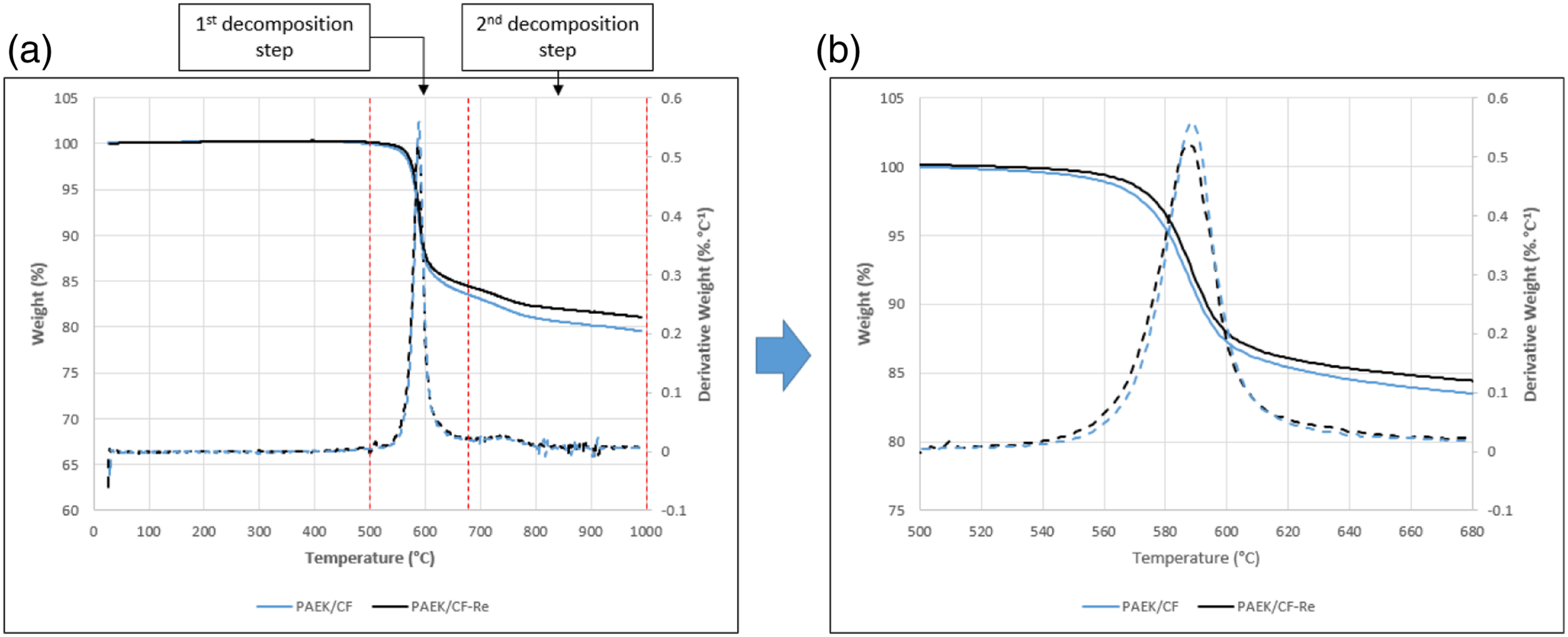
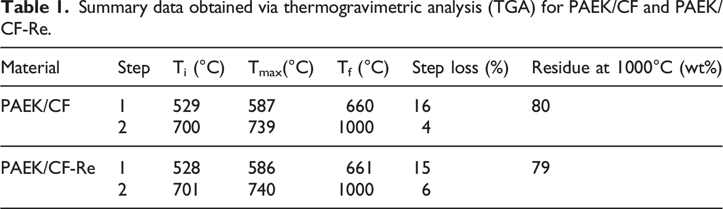
Summary data obtained via thermogravimetric analysis (TGA) for PAEK/CF and PAEK/CF-Re.
The DSC analysis can be used to assess some thermal parameters, such as melting (Tm), crystallization (Tc), glass transition (Tg) temperatures, and crystallization level. The technique is also applied to study the crystallization level of the semicrystalline polymers.
34
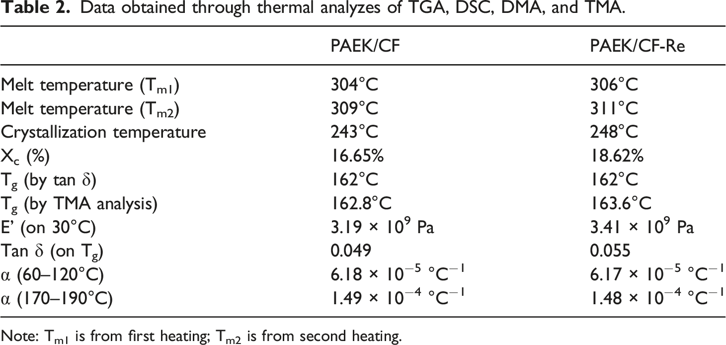
The heat flow as a function of temperature is shown in Figure 4 as well as the collected data summarized in Table 2. The melting temperatures in the first and second heating remain only with a variance of 2°C between PAEK/CF and PAEK/CF-Re laminates. However, differences between the crystallization temperatures were slightly superior, (5°C) revealing variations in the crystallinity. As can be seen, the crystallinity was around 16.65% and 18.62% for PAEK/CF and PAEK/CF-Re, respectively. This fact can be attributed to the five-Celsius disparity in crystallization temperature previously observed. The crystallization of the polymers depends on the cooling rate, having, thus, a high impact on the mechanical properties of the composites. The first stage corresponds to the primary crystallization, where the organization of the lamellae in spherulites occurs. Differently, the second crystallization occurs in the interlaminar spherulitic region.
37
Differential Scanning Calorimetry results obtained for PAEK/CF and PAEK/CF-Re with a magnification in the areas corresponded to the melting and crystallization temperatures. Data obtained through thermal analyzes of TGA, DSC, DMA, and TMA. Note: Tm1 is from first heating; Tm2 is from second heating.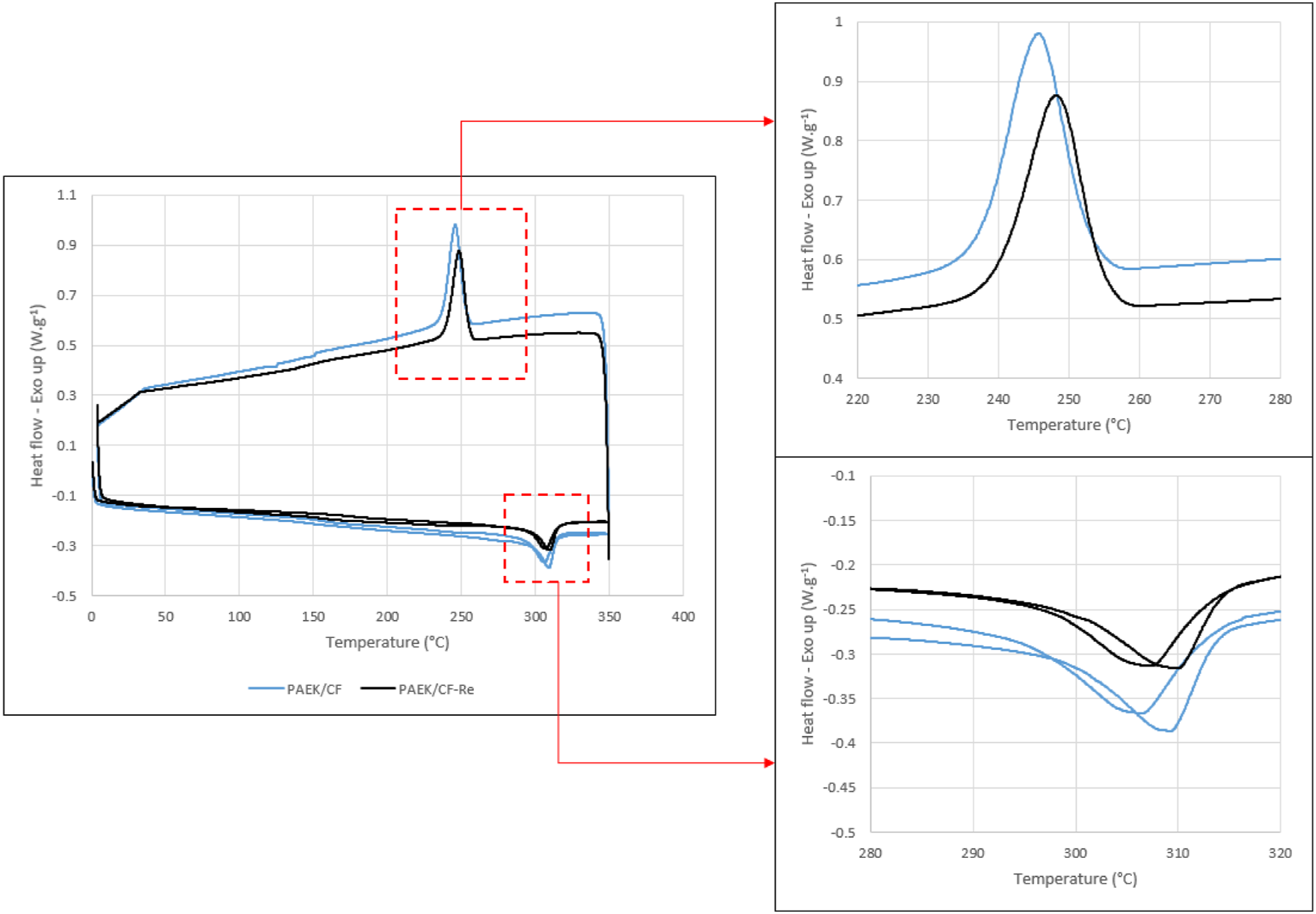
Dynamic mechanical analysis is a sensitive technique that allows the study of polymeric chain relaxation, such as the glass transition temperature and how the mechanical properties change when relaxation is observed. 35 Also, DMA provides information about stiffness and damping properties. Stiffness is dependent on the dimensions and mechanical properties whereas, damping is associated with the amount of energy that the material can store. Figure 3(a) shows the curves of the storage modulus (E') and Tan δ as a function of temperature for the studied materials. As can be seen, both laminates show similar behavior, which means the storage modulus remains practically the same with increasing the temperature. Also, the curves show a drop between 125°C and 190°C, which corresponds to the glass transition of the materials. This drop is attributed to a phenomenon of energy dissipation involving cooperative movements of the polymer chains. 38
Although both laminates have similar viscoelastic behaviors, it appears that the reconsolidation supported the increment of E' due to the increase of the storage modulus varying from 3.19 (PAEK/CF) to 3.41 (PAEK/CF-Re) GPa. Also, an increment in the damping capacity was observed, suggesting an increase in the capacity of the material to store energy, as verified by the boost in Tan δ from 0.049 (PAEK/CF) to 0.055 (PAEK/CF-Re). The increase in E’ and Tan δ may be associated with an optimization of the fiber/matrix interface promoted by the reconsolidation process added to the change in crystallinity.
Thermomechanical analysis, besides providing the glass transition temperature also commits the coefficient of thermal expansion (CTE). This parameter is a criterion for obtaining the dimensional stability of the material. The curve of dimensional change versus temperature obtained through TMA analysis is shown in Figure 5. The Tg values for both materials are practically the same, with only a 0.8°C variation. Also, the results are close to the values obtained by DMA, as visualized in Table 2. (a) Viscoelastic behavior through dynamic-mechanical analysis and (b) thermomechanical behavior through TMA analysis for PAEK/CF and PAEK/CF-Re.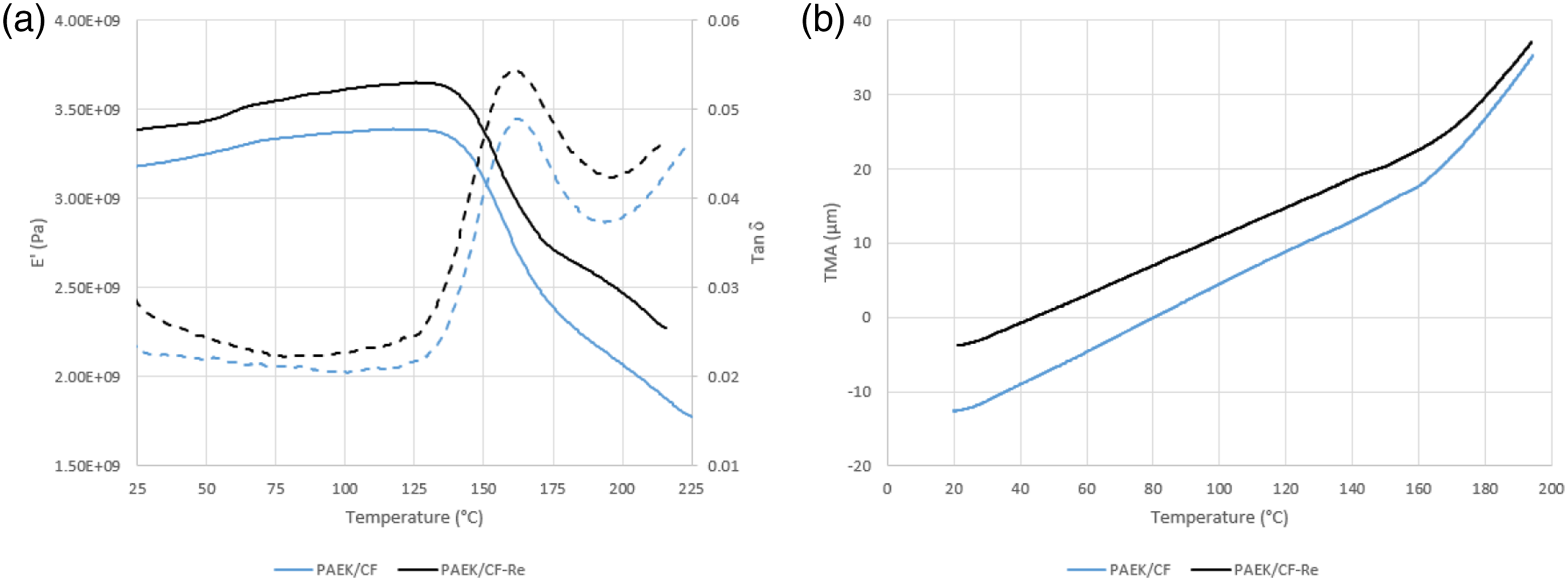
The CTE was analyzed in the glassy (before Tg) and rubbery (after Tg) region, as displayed in Table 1. For both regions, there is no variation in the CTE of the composites, even after the reconsolidation. Therefore, the reconsolidation does not change the dimensional stability of the composites under mechanical and thermal stresses. Also, the laminate shows that, even after reconsolidation, the material remains capable of maintaining its size, regardless of environmental conditions.
Mechanical properties
Figure 6 displays the global impact response under three impact energy levels (5, 10, and 30 J) through force-time, force-displacement, velocity-time, and displacement-time curves for PAEK/CF and PAEK/CF-Re laminates. The data collected from the impact curves for all laminates are summarized in Table 3. Figures 4(a) and (b), force-time curves, show the impact force keeps zero at the beginning (0–5 ms), increases sharply up to its peak (5 to 8 ms), and then returns to zero from 12 to 14 ms. It is worth mentioning that some irregular behavior (oscillation) occurs for higher energy levels close to the peak, which suggests the laminates were severely damaged at that point. According to the literature,
39
the oscillation points is associated with the existence of progressive damage whereas, a smoother curve is a sign of less severe disturbance. As can be seen, the impact curve of 5 J is more fluid than those of 10 and 30 J, in other words, lower energy levels lead to less severe damage in the laminates. Also, no sudden drop in the impact load is noted, which means no penetration occurred in the damage process. It is important to point out that both types of composites (PAEK/CF and PAEK/CF-Re) exhibit the same trend of load history. Force–time, force–displacement, and velocity–time, curves for PAEK/CF (a, c, and e) and PAEK/CF-Re (b, d, and f) composites. Impact parameters for PAEK/CF and PAEK/CF-Re composites. aReconsolidated.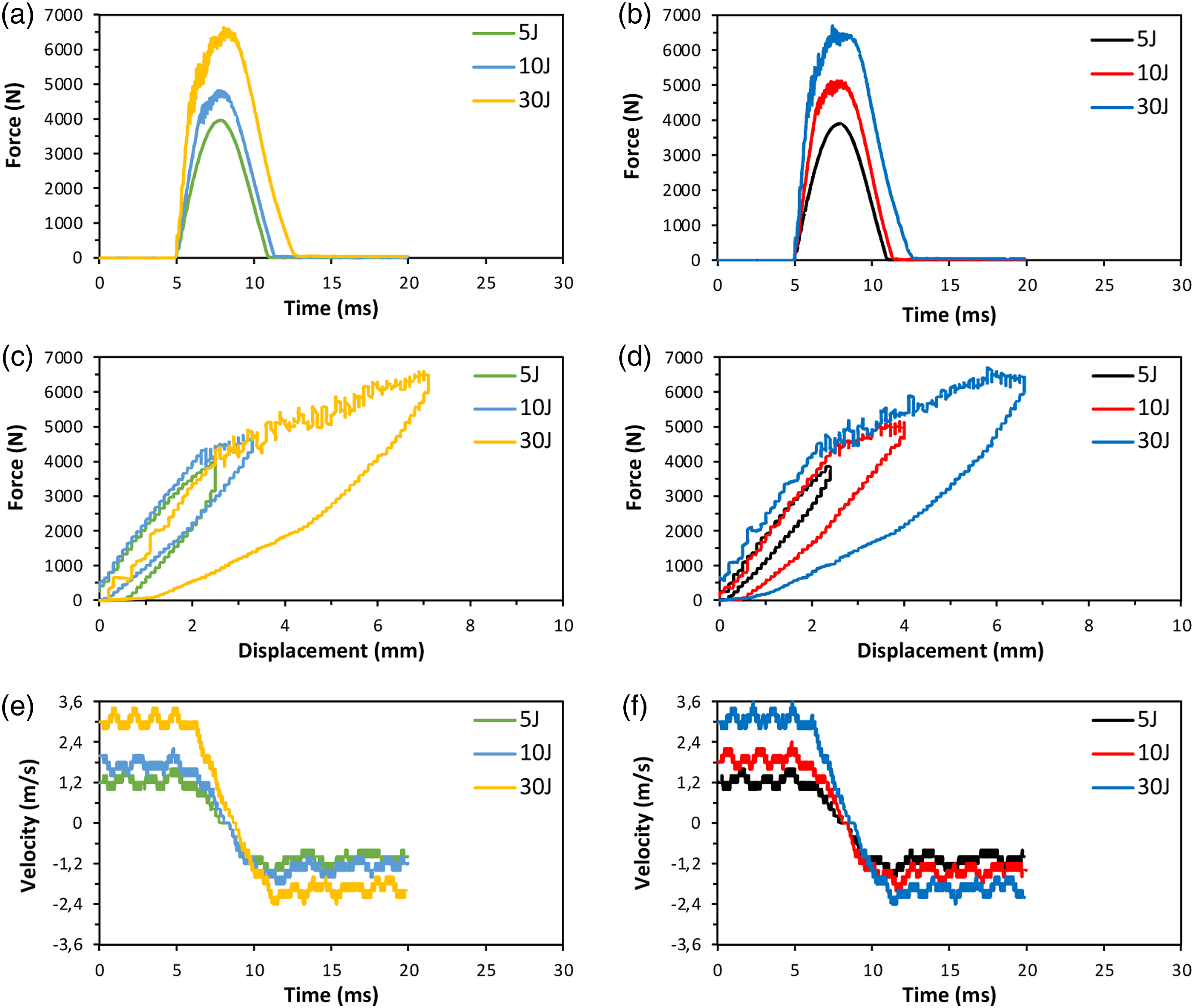
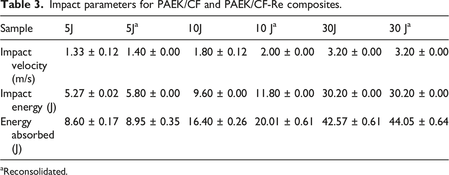
Figures 6(c) and (d) show the force-displacement response for both studied laminates under 5, 10, and 30 J. As can be noted, all curves for both composites systems display a closed-loop behavior, suggesting no evidence of penetration once the incident energy, the potential energy of the mass, was converted in kinetic energy. Also, the impact phenomenon is transferred as deformation energy to the specimen and the transfer is complete when the displacement reaches its max value. As the laminate reaches the maximum displacement, the energy restitution (spring back) phase begins. This phase is complete when the force applied by the dart becomes zero and the dart ends in contact with the specimen. 40 The increase of impact energy increases the displacement of the composites, revealing maximum displacement values of 2.5 mm (5 J), 3.3 mm (10 J), and 7.1 mm (30 J) for PAEK/CF laminates. The same trend is observed for the reconsolidated samples showing results of 2.4 mm, 4.0 mm, and 6.6 mm for impact energy levels of 5, 10, and 30 J, respectively.
The law of conservation of energy states the total energy before impact is equal to the total energy after the impact.
41
Besides, the deformation of the laminate is originated from the kinetic energy from the impactor.
42
The force-displacement curve has a loop behavior so that the upper part is the loading part, and the area corresponds to the energy transfer from the dart to the specimen. The area below the lower part is the elastic energy restituted by the specimen to the dart and the inside area is the absorbed energy, mainly due to material damage. Therefore, it is reasonable to propose the energy absorbed by the specimen is comparable to the energy that is consumed during the formation of damage so that high absorbed energy values would correspond to severe damage in the composite. The energy absorbed can be calculated by integrating under the area of the force-displacement curve as described: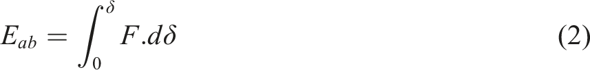
The absorbed energy values are listed in Table 3. As can be noted, the amount of absorbed energy increases as the impact energy level increases. Also, PAEK/CF-Re composites present a higher energy absorption in comparison to PAEK/CF laminates for impact energy levels of 5 and 10 J, which suggests PAEK/CF-Re samples are more vulnerable to severe damage at a low impact energy level. It is worth mentioning that for high energy levels (30 J), the absorbed energy for both composites systems studied in this work was the same.
Figures 6(e) and (f) show the velocity-time response for PAEK/CF and reconsolidated composites under impact energy levels of 5, 10, and 30 J. According to the literature, 39 the positive section of the velocity-time curve expresses the downward motion as long as the negative value exhibits the upward motion due to the striker rebound. As can be noted, both laminates show similar behavior which is complex to detect divergences in PAEK/CF and reconsolidated laminates graphs. With the assistance of Table 2, for low impact energies (e.g., 5 and 10 J), reconsolidated materials present slightly higher impact velocity values than base laminates. However, for impact energy levels of 30 J, both composites present the same impact velocity of 3.2 m/s.
The impact speed is calculated by the system software (IAF ImpactLogger) that is connected to the testing machine and uses the relationship between the energy before and after the impact to establish the speed (v) of the impact. Leaving in the relationship only the dependence of the height at which the impact mass was positioned (v = (2gh)1/2), where g is gravity and h is the height of the impact mass. Thus, the impact energy (E) is equal to: E = ½ (mv 2 ), where m is the impactor mass.
The ultrasonic analysis is a non-destructive technique that allows the identification of cracks, delamination, and general defects that occurred during the lamination of the material.
43
C-scan is used to assess the defects induced during the manufacturing process of the composites, as can be visualized in Figure 7. The consolidated area of the PAEK/CF composites (Figure 7(a)) shows a homogenous green color with only one small defect put in evidence with by a circle, which means the processing parameters employed in the preparation of the laminate were adequate. Also, the global thickness of the composite is around 3.75 mm, according to the scale color presented. Ultrasound images of the standard composites, specimens after impact testing, and after reconsolidation.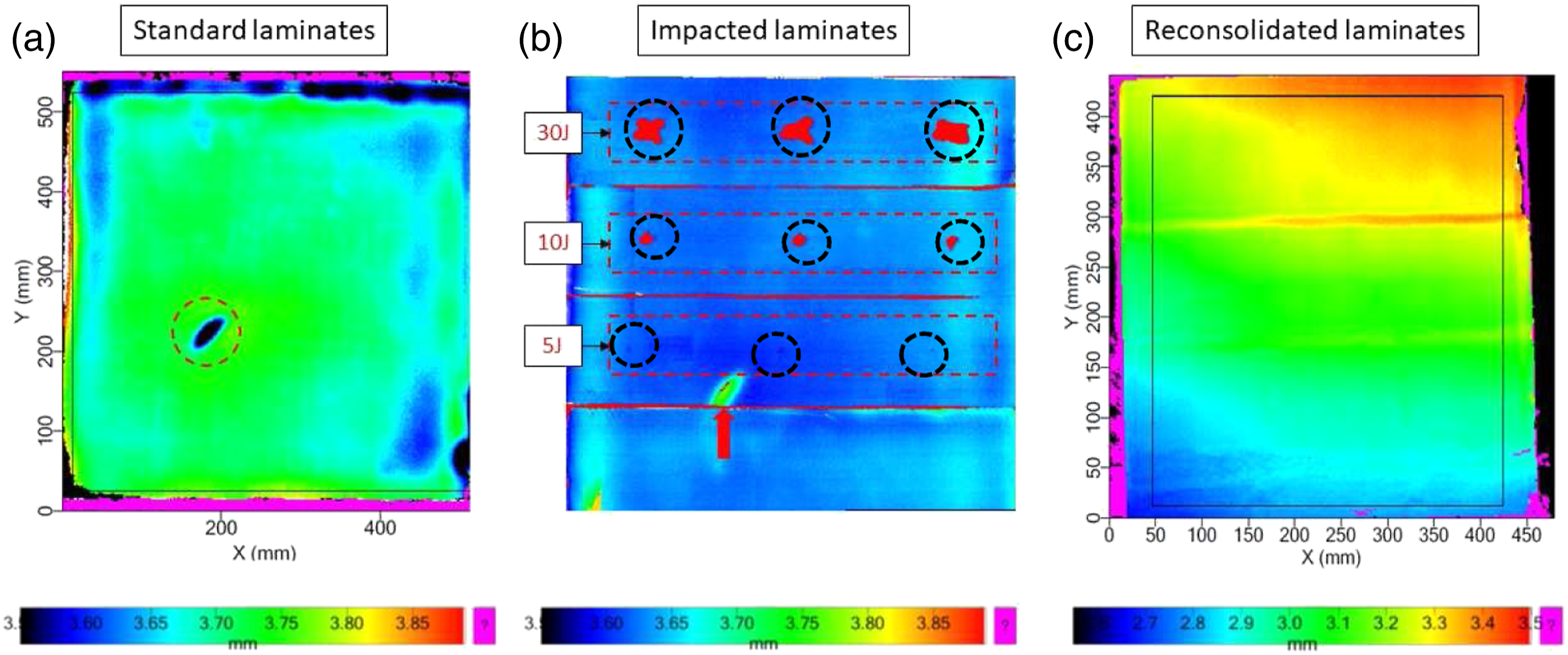
The impacted laminates with different energy levels are represented in Figure 7(b). It can be observed the laminate presents a homogeneous blue color, suggesting the thickness of the composite was slightly reduced after the impact tests. For an energy level of 5 J, the delamination area appears as a small dot, as highlighted by the dark circles. As the energy increases to 10 J, the delamination area increases as well, and the damage is mainly located in the upper and middle section of the circle. Also, no delamination occurs on the backside of the specimens. For an energy level of 30 J, the delamination contour shows an irregular shape with a larger delamination area, suggesting the damage in the material becomes serious under higher impact energy.
The C-scan image of the reconsolidated laminate is presented in Figure 7(c). As can be noted, no defects or damages in the laminate were found after the process. Also, it is worth mentioning that the thickness of the reconsolidated sample varies from 2.8 mm (lower left side) to 3.5 mm (upper right side). The central region shows a homogeneous green color, as also visualized by the base laminate, suggesting a thickness of 3.1 mm. In general, the reconsolidated sample presents smaller thickness compared to the base material and impacted composites once some amount of the polymer matrix squeezed out of the laminate during the reconsolidation process of the material.
Compression tests results for all composites studied in this work.
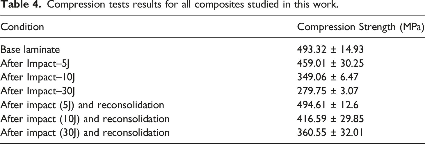
The reconsolidation process can be an alternative to improve the CAI results of the laminates, as demonstrated in Table 4. As can be seen, for all impact energies evaluated in this work, the compression strength for reconsolidated composites reached higher values compared to CAI samples. For instance, PAEK/CF-Re at 5 J shows compression results of 494.61 ± 12.6 MPa, which represents an increase of ∼ 8% compared to after impact composite at the same energy level. Also, the reconsolidated material is in the same range as the base laminate. Considering the energy levels of 10 and 30 J, the increase in compression properties for reconsolidated samples are higher, revealing gains of around 20% and 29% once compared to the after impacted laminates. Therefore, it is possible to attest that reconsolidation is a procedure to partially recover the compression after impact properties of the PAEK/carbon fiber composite.
The micrographs of CAI and CAI-Re samples at different energy levels are presented in Figure 8. All the specimens failed in the central region due to delamination along the width followed by fiber fracture. This behavior was also observed in other works available in the literature.28,45,46 The delamination also changed its plane and generated translaminar failures, as can be seen by the yellow and green arrows, respectively. By comparing CAI and CAI-Re samples, more cracks in the fracture region were observed for reconsolidated samples. This behavior suggests an increase of the delamination perpendicular to the compression direction
28
once samples submitted to the reconsolidation presented higher compression strength compared to CAI samples. In other words, higher compression strength requires more energy to fracture occurs. Only the sample impacted with 5 J and reconsolidated showed a catastrophic failure and broken in two parts (Figure 8(b)), as can be addressed to the highest compressive strength observed for this sample. Micrographs of CAI (a, c, and e) and CAI-Re (b, d, f) specimens.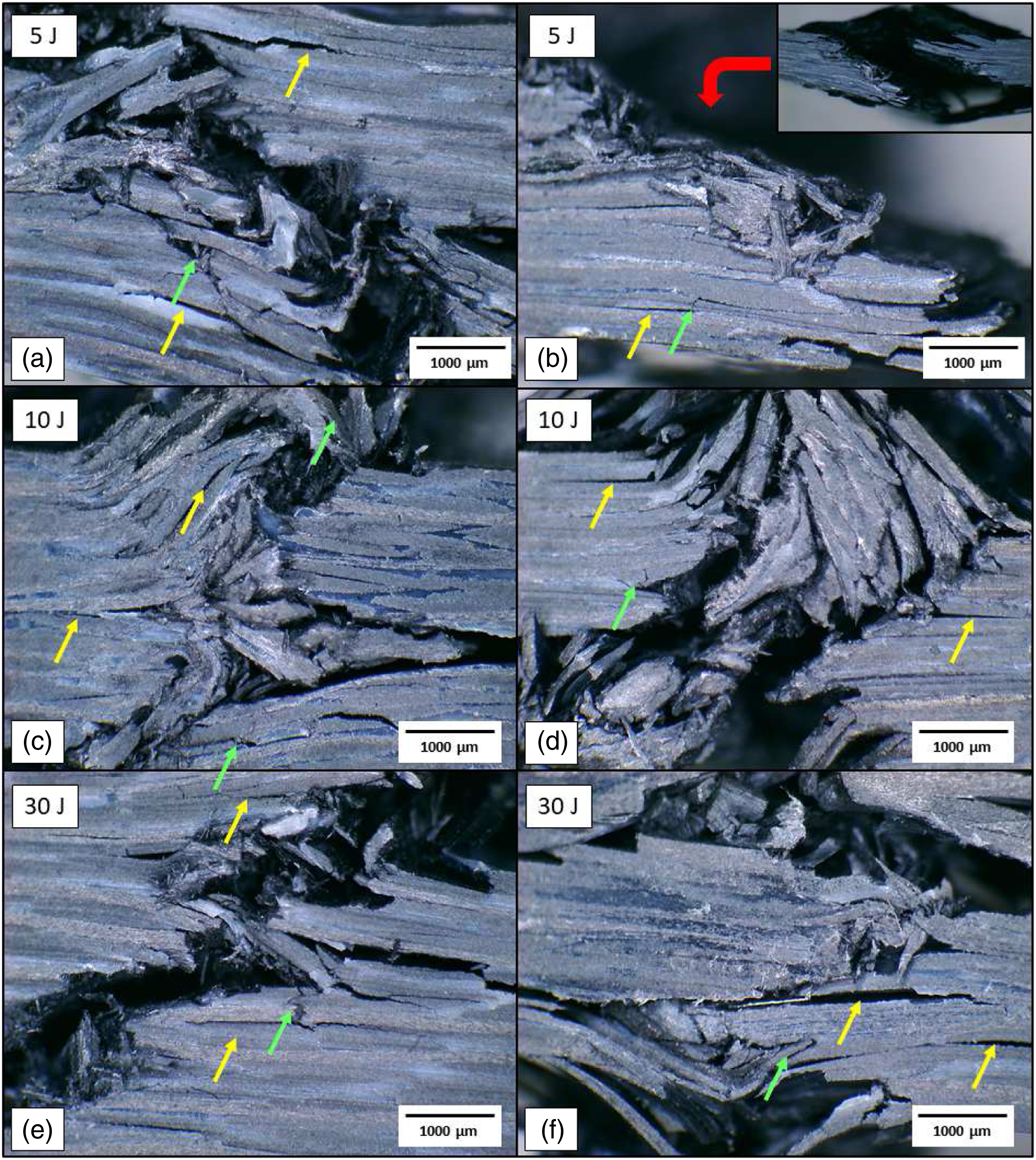
It is noteworthy that the micrographs are consistent with the data obtained, that is, the samples that was impacted with the highest energy (30 J) have more damages which resulted in a low compression strength and less damage features are observed. On the other hand, the lowest energy (5 J) resulted in a higher compression strength and more damage features are verified.
Conclusions
The reconsolidated procedure was used to evaluate the impact damage and CAI behavior of poly (aryl ether ketone) (PAEK)/carbon fiber laminates. After all the thermal and mechanical tests, it can be attested that the thermoplastic composite maintains its thermal properties regardless of the damage suffered. The impact responses of composite laminates (force-time, force-displacement, and velocity-time curves) exhibit similar variation tendencies for different impact energies evaluated. In the case of the properties analyzed by the CAI tests, it was observed that for low energies levels (5 J) the compression properties were fully recovered once compared to the base laminate whereas, for higher energies (10 and 30 J) the recovery was partial, revealing solid gains after the reconsolidation of the laminates. Thus, it can be stated that the material can be reused after impact damages using the reconsolidation methodology.
Footnotes
Declaration of Conflicting Interests
The author(s) declared no potential conflicts of interest with respect to the research, authorship, and/or publication of this article.
Funding
The author(s) disclosed receipt of the following financial support for the research, authorship, and/or publication of this article: The authors are grateful for all support given by Toray Advanced Composites (TAC), Thermoplastic Composites Research Center (TPRC) and University of Twente. The financial support given by the Brazilian Funding Institutions: São Paulo Foundation Research (FAPESP) (2017/16970-0, 2018/07867-3, and 2019/18691-6), National Council for Scientific and Technological Development (CNPq) (140852/2018-2, 306576/2020-1 and 304876/2020-8) and this study was also financed in part by the Coordenação de Aperfeiçoamento de Pessoal de Nível Superior–Brasil (CAPES)–Finance Code 001.