
Abstract
Composite materials have found widespread applications in the automotive, aerospace, and building industries. Several components are joined together for these applications, by some temporary or permanent bonding approach. The increased use of different materials and their combinations such as composites makes the whole joining process something to be thoroughly considered before continuing. Several aspects need to be studied before spending significant time and financial resources. Considering these challenges in this paper we have provided a review of the investigations that have been made on fiber-reinforced composite joints. The level of development in various types of joints and joining techniques such as mechanical bonding, adhesive bonding, and fusion bonding along with their advantages and disadvantages is given. Several parameters affecting the performance of composite joints such as joint configuration, material selection and properties, geometric parameters, dominating failure modes, and environmental factors are described briefly. To verify the performance of composite joints, guidance on joint testing is given (both destructive and non-destructive).
Introduction
Composite materials are in high demand owing to their advantages over traditional materials including flexibility of design, enhanced mechanical properties, and less susceptibility to weathering. 1 The application areas of composites include structures (buildings, bridges, etc.), aerospace, automotive, marine, etc.2,3 Among various composite materials, fiber-reinforced polymer composites (FRPC), specifically glass, carbon, and Kevlar fiber-reinforced composites are largely used in aerospace and aviation applications. Some typical examples are Boeing 757, 767, and 777 and the bigger aircraft models from Europe such as A330, A340, and super jumbo airliner A380. In vertical stabilizer total weight saving with carbon fiber reinforced composite is about 400 Kg, compared with previously used Aluminum alloy unit. 4 It has been estimated that a 1 kg weight drop saves around 2900 L of fuel per year. 5
Composite materials have been used in many structural applications and aerospace technology in the form of different components, ranging from hot-air balloons and gliders to passenger/fighter planes, space shuttles, beach starships wing assemblies,
6
helicopter rotor blades, seats, and instrument enclosure.
7
In the aerospace industry, composite materials are used in the main body structures with combinations of other materials.
8
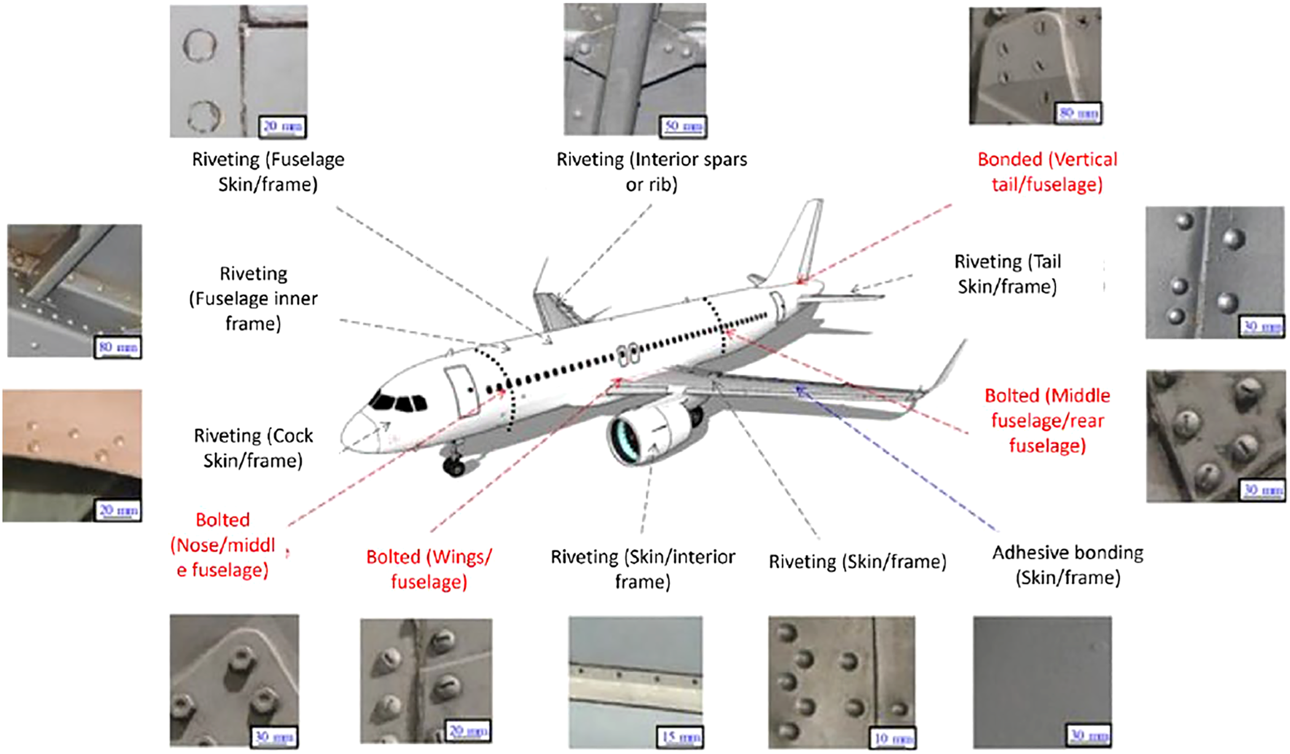
For example, Boeing 787 uses 50% composite materials, and 50% other materials like aluminum, titanium, steel, etc. When used to form a single structure, the composite materials need to be joined with other materials, either composites, metal, wood, or plastics. Figure 1 shows applications of various joining techniques in a modern aircraft structure. Joining applications and joining techniques used in an aircraft assembly.
9
Previously, thermosetting resins such as epoxies were used with reinforcement of short and continuous fibers for high-performance structural application. In the current era, the availability of thermoplastic resins has enabled the production of a wide range of weldable composite materials that fulfill the requirement of high-performance applications. 10 In thermoplastic composites, there is a specific challenge and design opportunity for high-performance continuous fibers composites comprising matrices like PEEK, PPS, and PP. These resins have much better properties in comparison with thermosetting resins, specifically, fracture toughness, damage tolerance, and resistance to severe weather conditions. A combination of thermoset and thermoplastic matrices is also being used for better impact performance.11–13
Joining structures certainly implies joining materials, and the increasing use of different materials and their combinations such as composites makes the whole joining process something to be thoroughly considered before continuing. Several aspects need to be studied before spending significant time and financial resources. Considering these challenges in this paper we have provided a review of the investigations that have been made on fiber-reinforced composite joints. Sufficient information on joining approaches enables the materials’ selection and whole design to assist the joining mechanism while retaining structural performance instead of potentially compromising the system.
Significance of joining of components
The need for structurally stable, practically solid joints is a design plan issue that extensively originated before the advancement of present-day fiber-reinforced composite materials. The utilization of such materials in complex structures perpetually creates a less intricate design that requires less discrete parts than an identical metal structure. Thus, a huge weight reduction is generally acknowledged just as a decrease in the quantity of joining tasks and essential joining methods, consequently upgrading dependability, and bringing down expense. Even though the quantity of joints is decreased, the necessity for joints is never eliminated. The performance of a structure is fundamentally dependent on the behavior of the joints it contains. Therefore, the mechanical performance of a joint is more important because the overall performance of the structure depends upon the performance of the joint. 14
The joining of metals components is already a well-known technology that includes riveting, bolting, welding, brazing, and many other techniques. On other hand, polymer composites are mostly amenable to adhesive or mechanical bonding. Exertion and consideration have been given to the localized welding of thermoplastic composites. Adhesive bonding is commonly favored over mechanical welding considering the uniform joint that can be accomplished. Drilling of holes for mechanical welding causes stress concentration points that could affect the mechanical performance of material but the need for removable parts in certain congregations and the requirement for inside access can easily be addressed with mechanical joints. 15
Applications of the thermoplastic composite are increasing very rapidly as a replacement of metals and thermosetting composites. 16 Consequently, the researchers are working to improve the existing joining methods as well as to devise new joining approaches for thermoplastic composites, that can easily bear the static and dynamic loads in aerospace vehicles. 17 In addition to joining techniques, the joint configuration also impacts the performance of the composite structure. Several joint configurations and joining methods have been used for the joining of different composite materials depending upon the application and composition of that composite part. In aircraft structure, a combination of adhesive and mechanical fastening is used to join composites, while only adhesive bonding is done for automobiles.
Joint configurations
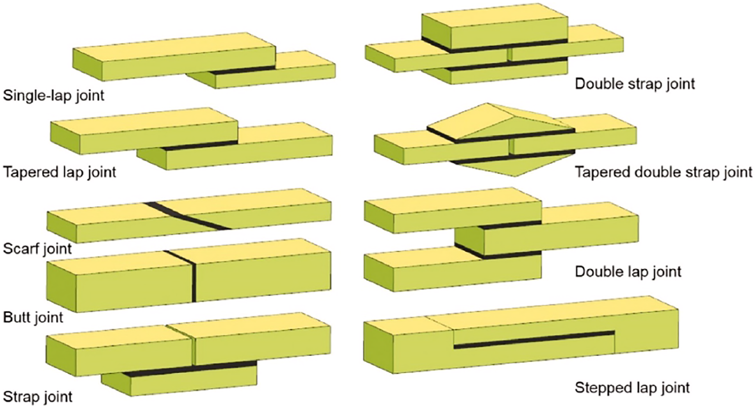
The geometrical configuration of a joint defines the overall performance of the joint. During the design phase, the effect of stresses needs to be considered that will act on the joint of a certain configuration. There are several joint designs available or can be produced according to the requirement or types of loads that the structure is designed to bear during its service life. Some commonly used joint geometries include Lap, Butt, Strap, and Scarf joints, as shown in Figure 2. Several variations of these basic configurations are possible. Schematic of different joints.
18
A single lap joint is the most common metal to the composite joint in the automotive and aircraft industry, with a simple manufacturing method. It is produced by simply overlapping both the adherends and joining them by some joining means. 19 However high interfacial stresses at the end of the lapped region and intrinsic eccentricity make it inefficient for transferring load. By non-symmetric load, the adherends can rotate, which leads to premature failure of the joint.20,21 But, with thin adherends, no significant difference is observed in the joint strength of these configurations. The fascination with the lap joint is frequently determined by its simplicity of development and ease. The scarf joint is characterized by increased complexity and cost, although performance also increases as they produce a minor alteration in the load path. A tapered lap joint is considered to be more efficient compared to the lap joint. 22
A straightforward change from a single lap joint through a ventured setup to a scarf joint and at last a butt joint. The Butt joint is formed by the end-to-end joining of two pieces without overlapping and is preferred only when the adherends have sufficient thickness. These are not used generally when composite to composite (thin skin) or composite to metal joining is required. Another limitation of this joint is the inability to withstand the bending forces that cause cleavage stresses. Additionally, it is difficult to align two adherends during their manufacturing. 23 Scarf joints developed using adherends of matching stiffness are the most efficient joints theoretically, with potential elimination of stress concentration areas. The superior performance of these joints is the result of avoiding joint eccentricities. Among these joint configurations, stepped lap and scarf joints are considered more efficient as they produce a minor alteration in the load path. Although single lap joints and double lap joints are considered less efficient due to their ease in fabrication and simplicity, these are still widely used in aircraft structures.
Joining techniques
As mentioned earlier, several methods are being used for the joining different parts of composites depending upon the application area. The joining techniques are broadly classified into mechanical, adhesive, and fusion bonding, as shown in Figure 3. Classification of joining techniques.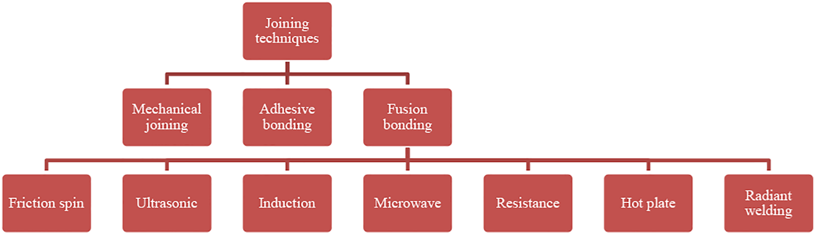
Mechanical joining
The mechanical joining method is used to produce joints by using only mechanical forces. A supplementary device such as a bolt, rivet, or screw causes interference between parts. Based on the type of supplementary device, mechanical joining is subdivided into riveting and bolting. For polymer matrix composites, in particular, mechanical joining methods have been used. 24 Joining of composite materials by mechanical means (bolts and rivets) is achieved by drilling a hole in the components, and subsequently joining using rivets or bolts.
The oldest method of joining different composite materials is riveting. Riveting is not only the oldest joining technique but also the most reliable method for joining different materials.
25
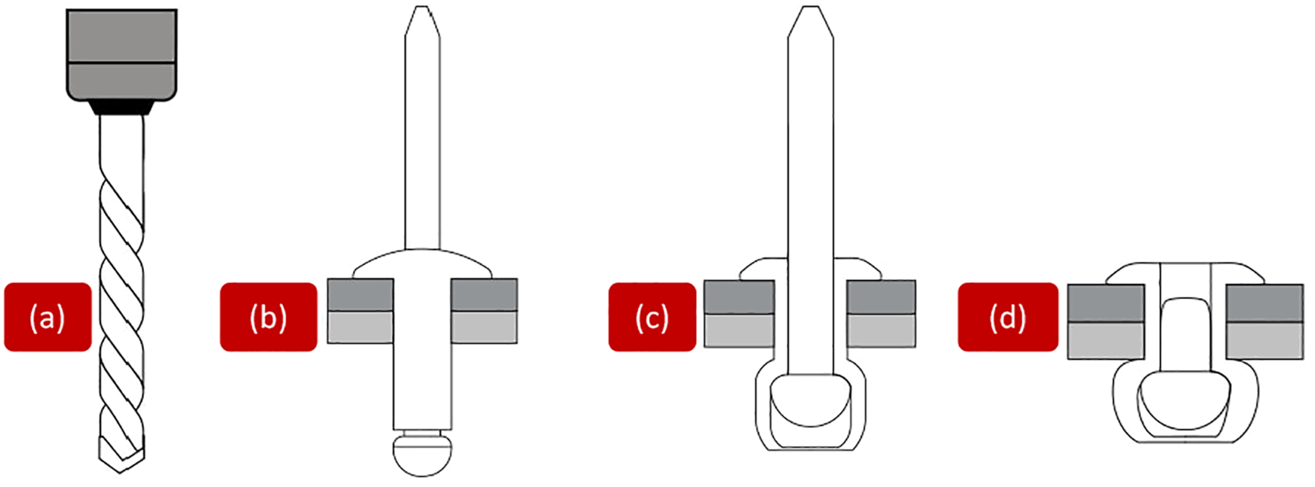
It is a preferred joining approach used in large airliners, freight aircraft, lighter fighter trainers, choppers, and cargo planes. However, a significant weight increase in the product is observed due to riveting which may reach up to a few tons, and this additional weight affects the performance and fuel efficiency of the product. Riveting is used because it is easy to apply, and compatible with every type of material like metals, composites, alloys, ceramics, etc. The riveting mechanism is shown in Figure 4. Riveting mechanism (a) drill hole in joining components; (b) positioning of joining components, and rivet insertion; (c) rivet tightening and joint consolidation through pressure; (d) a consolidated joint.
26
In the case of FRPC, drilling for mechanical fastening breaks the reinforcement fibers, and the hole may produce damage and variations in the composite parts. These damages result in the strength degradation of the composite part. 25 The drilling-induced damages can be reduced by the appropriate selection of the drill material and geometry. Jia et al. 27 investigated that by using an intermittent Sawtooth drill, the cutting direction can be reversed from downward to upward by cutting the lips of the drill, which reduces the damage that occurred due to drill exit. In another study, it was reported that adjusting the top angle of the drill to a bit less than 110° can prevent the drilling-induced delamination in carbon/epoxy composites. 28 Another approach is to insert metallic parts during composite fabrication, but it requires much precision.
Mechanical fasteners such as bolts or rivets can be removed with or without damaging parts. Thus, mechanical joining is advantageous in some ways, as parts can be disassembled on purpose such as repairing or part replacement. Another advantage is that joining can be achieved without altering the composition of the materials comprising parts. 29 When we discuss the joining method for aerospace applications, an increase in the weight of the product due to the bolts and rivets is a major concern of mechanical joining. Therefore, other methods rather than mechanical joining like fusion or adhesive joining need to be considered for aerospace applications.
Adhesive bonding
This approach uses an adhesive material, placed between adhered surfaces to form an adhesively bonded joint upon solidification. It is increasingly used as an alternative to conventional mechanical joining for engineering applications. In adhesive joints, stress distributions are even because we do not have to drill the holes for rivets and bolts as we did in mechanical joints. Some other advantages of adhesive joints include low fabrication cost, design flexibility, low structural strength to weight ratio, and high damage tolerance. The schematic of adhesive joining is shown in Figure 5. Adhesively bonded joints have various application areas ranging from traditional to high technology industries such as packaging, sports, construction, electronics, aerospace, and aeronautics.30,31 The structural configurations include various resins, fiber types, structures, and weaves.
32
Adhesive joining mechanism.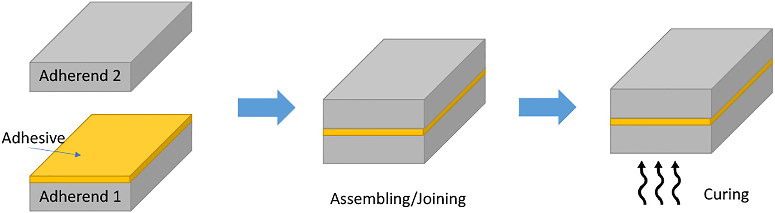
The limitation of this joining technique is that disassembling of these joints is not possible without damage, and these joints are also sensitive to environmental conditions such as temperature and humidity. 33 Another drawback with the adhesive joining technique is that researchers are very uncertain about the performance of these joints, they are unable to predict whether the joint fails instantaneously or progressively. Even if a joint passes laboratory testing the design engineers are unable to predict whether the joint will withstand the estimated loads during its lifespan. Due to these reasons some designers suggest developing hybrid joints, using both mechanical and adhesive joining techniques. It is a relatively less explored area and to date, limited data is available on the failure behavior and joint strength of the hybrid joints. 34
Fusion bonding
Thermoplastic composite materials are preferred over thermoset materials because they can be melted and reshaped. According to the literature, the thermoplastic material can be remolded indefinitely by using adequate temperature and pressure.35,36 The schematic of the fusion joining process is shown in Figure 6. Several variants of fusion bonding are available and are explained in the subsequent sections. The long molecular chains in thermoplastic polymers allow the heating and remelting of resulting composites. This phenomenon enables the joining of thermoplastics using a wide variety of fusion bonding techniques.37,38 Schematic of fusion joining mechanism.
26
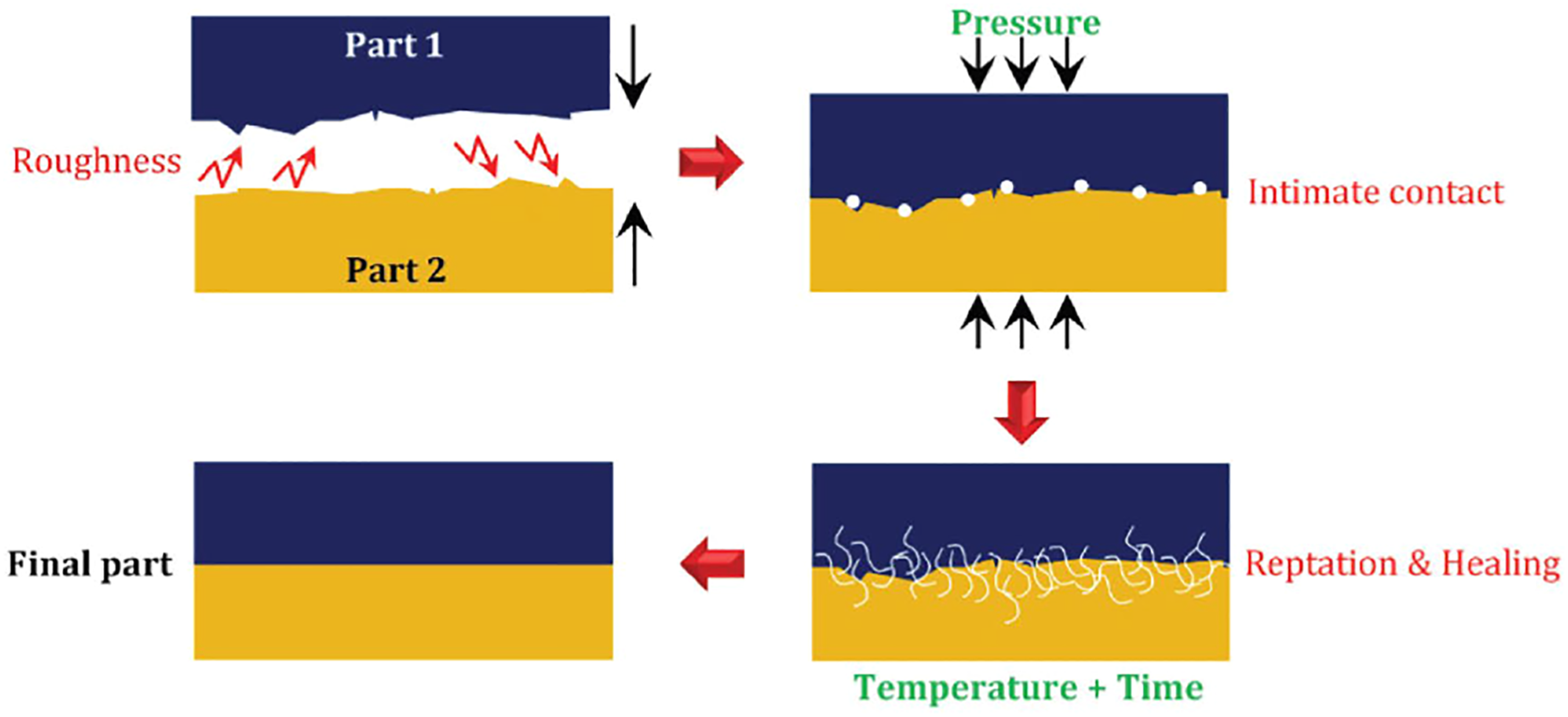
Butler et al. 39 reported that during fusion bonding, healing, and intimate contact are the key parameters that govern the strength development at the interface. The term healing is used to describe the migration of polymeric chains across the polymer interface, while intimate contact refers to the surface area physically contacted at the interface. They also proposed a theoretical model based on coupled bonding that considers the change in healing time due to growth in the intimate contact area.
Friction spin welding
The friction spin welding technique involves heat generation by the mechanical friction between a moving and a stationary component. A lateral force is applied to the parts at the same time, to plastically displace and fuse the material. The two parts to be joined are clamped together, one part is held stationary and the other is vibrated against it. Heat is generated due to friction along with the common interface that joins the two components. The schematic of this arrangement is given in Figure 7. Machines utilized for friction spin welding resemble a motor machines. They require a high axle speed (12,000 r/min) to turn one section at a fast rate and methods for applying a hub pressure (∼ 50 kN/cm2) between the pivoting and the non-turning parts. Other variants of frictional welding include friction stir and friction linear welding.
40
A schematic of the friction spin welding mechanism.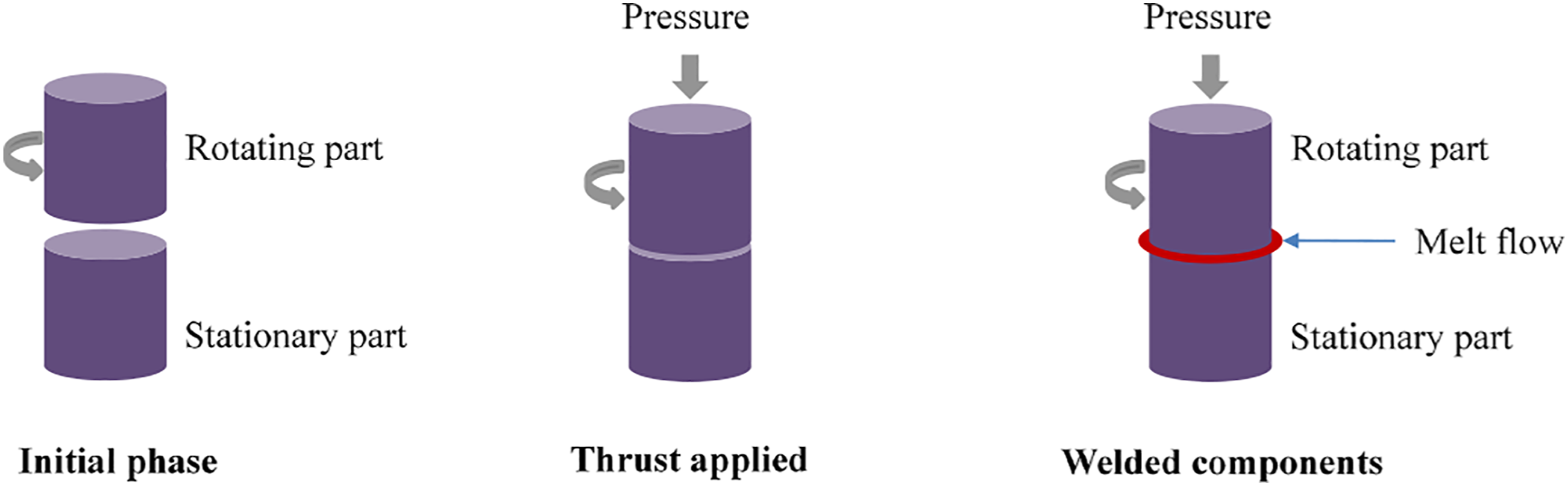
Friction spin welding can deliver top-notch welds in a short process duration; accordingly, it is appropriate for programmed large-scale manufacturing. The procedure is fit for welding carbon, alloys, stainless steels, aluminum, copper, and nickel alloys, and is equally suitable for thermoplastics and their corresponding composites.41,42
Ultrasonic welding
The ultrasonic welding technique joins the plastics using high-frequency longitudinal vibrations while holding together the workpieces under a certain pressure between the anvil and horn. The capacity to weld at least two segments utilizing ultrasonic welding relies upon material physical properties, recurrence, and amplitude of the ultrasonic wave and joint structure. This joining procedure can be applied indistinguishably to non-crystalline (welding temperature between the Tg and Tm) and semi-crystalline polymers (welding happens at the melting temperature).43–46 Figure 8 shows the schematic of an ultrasonic welding machine utilizing a piezoelectric transducer, which produces motions by applying electrical force at a high frequency. Schematic of an ultrasonic welding machine.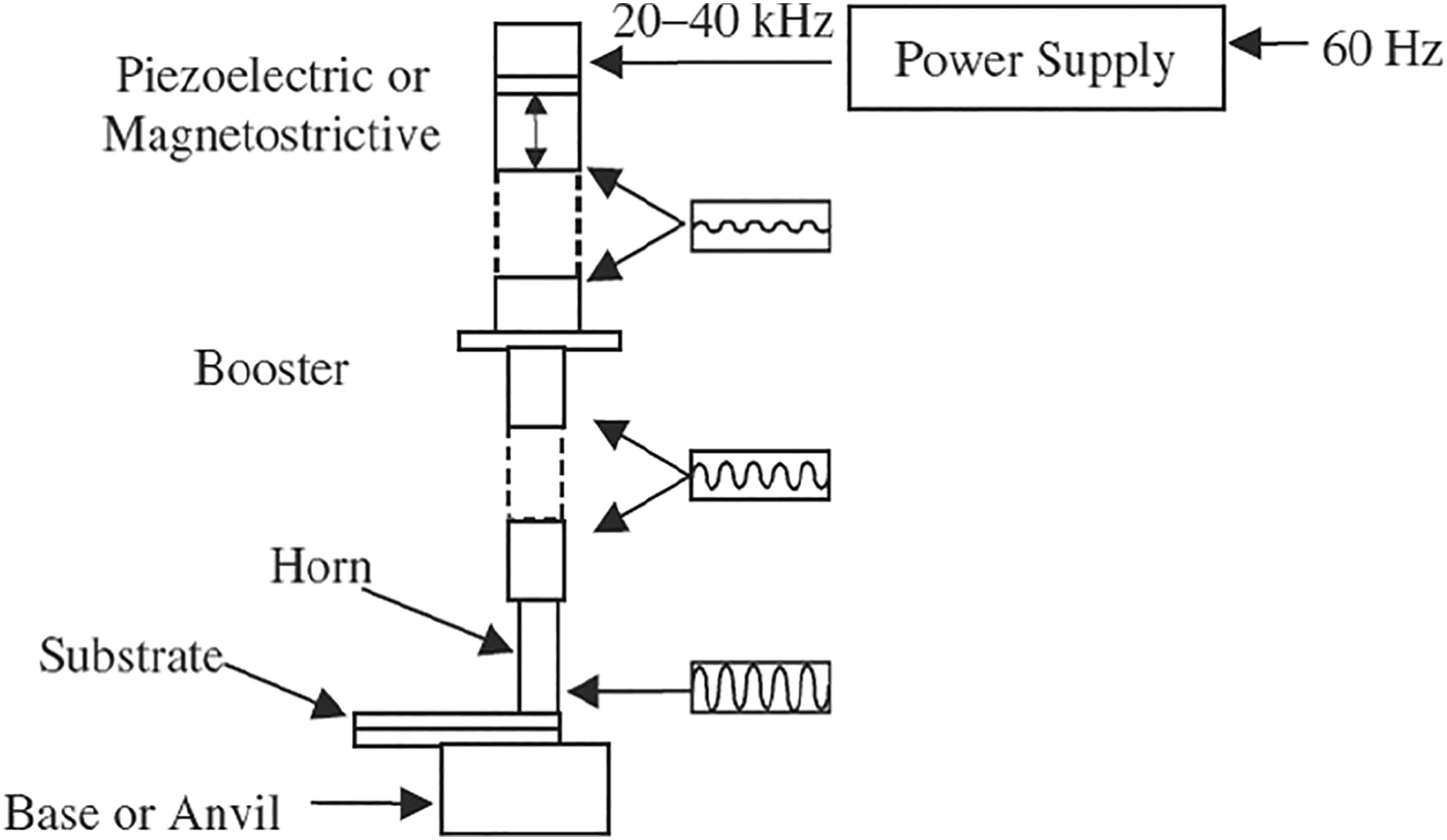
The use of ultrasonic welding is very broad in numerous modern branches including electrical, automotive, aviation, vitality, clinical, and bundling. Specifically, the aviation business utilizes this strategy to joint lightweight thermoplastic matrix composite materials, and various characterizations have been directed to discover ideal boundaries and procedure windows to create top-notch welds. 47 This technique was likewise utilized by Lockheed-Georgia to weld thermoplastic/graphite tape materials together for the C-130 Hercules airplane. Villegas and Palardy 48 investigated the role of integrated triangular energy directors (ED) on the weld strength of ultrasonically joined Carbon Fiber/PPS composites. The EDs are resin protrusions present on the surface to be joined by ultrasonic welding. Single lap shear joints were developed, and lap shear strength was determined as a function of the vibration time, and stage in the welding process. The lap shear strength (LSS) determined within stage 4 was 34.2 ± 1.5 MPa with triangular Eds, which is somewhat lower than the LSS of 37.1 ± 1.3 MPa obtained for joints with flat EDs.
Induction welding
Inductive heating is used in welding zones to melt the polymer matrix for producing joints by induction welding. The segments to be joined are subjected to an exchanging electromagnetic field. When there are electrically conductive loops in the part, for example, carbon fibers used as reinforcement, eddy currents are initiated that cause efficient localized heating. But in the case of glass fiber reinforced composites, we need to use some extrinsic electromagnetic susceptors, because the glass fibers are electrically non-conductive. These inserted susceptors convert the magnetic energy into thermal energy. Because of ferromagnetic materials, heat is generated by hysteresis effects. There are two major mechanisms of heating, i.e. energy dissipation due to hysteresis and due to Joule heating. The heat produced (Q) is determined by equation (1). Schematic of induction welding showing current induced by an electromagnetic coil.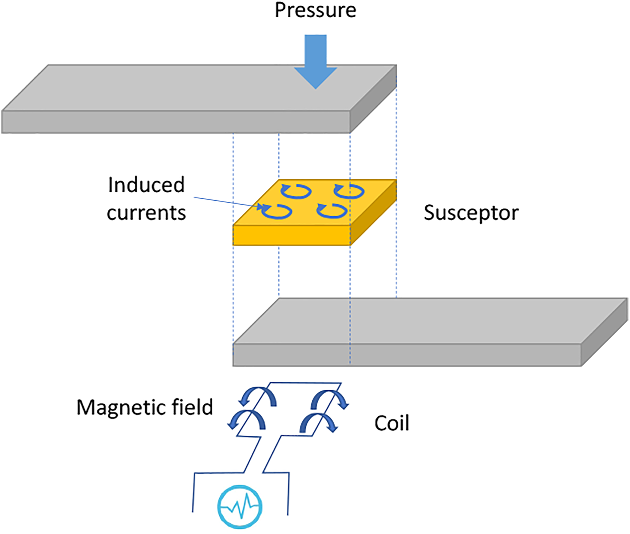

There are three different heating mechanisms during induction welding of thermoplastics, as reported by Yarlagadda et al.
50
and Kagan and Nichols.
51
(a) Fiber heating: results from Joule losses due to intrinsic resistance heating of fibers
52
; (b) Dielectric hysteresis heating: the matrix layer separates the fibers in a laminate. Dielectric heating occurs due to the movement and line up of molecules between the fibers
53
; (c) Contact resistance heating: it occurs on high fiber-fiber contact points
Kim et al. 54 presented a numerical model based on a unified approach to defining the in-plane heat generation during induction heating of carbon fiber composites. The model considers all three different heating mechanisms during induction welding, as discussed earlier. three possible heating mechanisms: Yarlagadda et al. 50 studied the induction heating of conductive composites and presented a unified approach to identify dominant heating mechanisms. Fink et al. 55 experimentally validated the theoretical models used for heat generation in the induction processing of carbon composites. They also proposed a theory of heat generation by magnetic induction in cross-ply carbon composites. 56
A unique approach to induction welding is the EMA weld bonding. This approach uses thermoplastic implants between the parts to be welded. This implant is composed of thermoplastics with ferromagnetic particles (e.g. iron). The heating is generated in these ferromagnetic particles, leading to the joining of both components. The EMA weld bonding is quick in contrast to ordinary induction welding. But, small cracks due to the ferromagnetic particles in the welding region, may affect the mechanical performance of the joint.57–59 Xiaolin et al. 60 developed a FEM model for ultrasonic welding of CF/PEEK laminates, based on the viscoelastic dissipation theory. They considered the effect of energy director size and apex angle on the heating process during ultrasonic welding.
Studies showed that under the equivalent heating parameters the joints produced by induction welding exhibit higher shear strength than resistant welded joints. Induction heating is not only suitable for the construction of carbon fiber reinforced composite joints but can also be used in repairing of F-111A aircraft horizontal stabilizer leading edge demonstration component, using the graphite fiber for conducting element. Structural element manufactured by using induction welding is better than those produced by autoclave co-consolidation. 51
Yarlagadda, Fink, and Gillespie 61 introduced a novel concept of using metal mesh susceptors to achieve uniform in-plane temperature. The cut pattern in the mesh can be optimized to reduce temperature gradients in the susceptor. Results for mesh with cut pattern show significant variations in heating compared to the uncut mesh. Suwanwatana et al. 62 investigated the bonding of thermoplastic composites by magnetic particulate susceptor materials for hysteresis induction heating. The bond strength of so-bonded materials was found comparable to that of autoclave-welded composites. The macroscopic failure modes in these bonded specimens included adhesive composite/film, cohesive composite, and cohesive film. Tay et al. 63 explored the possibility of accelerated adhesive curing in bonded joints by using magnetic susceptors during induction heating, specifically for repairing applications. This approach is suitable for localized heating of adhesive bondline, providing rapid curing if suitable susceptors are selected. The test results showed no significant reduction in the strength of bonded joints (single lap shear and double notched shear) with embedded susceptors.
Microwave welding
The chance of utilizing microwaves to weld parts has existed since the improvement of the magnetron. Its utilization in the frequency from 1 to 100 GHz has been accounted for in the previous studies to weld thermoplastic composites. 64 The temperature of mostly thermoplastic materials will not rise by placing them into the microwave. Therefore, some microwave susceptible materials are added around the line of the joint that allows localized heating. Plastic melts during simultaneous heating of microwave and applied pressure, and results in the welding. Suitable microwave susceptible materials include carbon, metals, or other conducting polymers. 65
The specific advantage of microwave welding over other welding techniques is its ability to illuminate the whole part and therefore produce complex three-dimensional joints. The whole process of welding is usually completed in less than 1 min. One disadvantage of microwave vitality is that homogeneous material heating is just conceivable with straightforward geometries or through the intricate adjustment of the radiation gear to a job that needs to be done. This method, in any case, is completely reasonable for what are typically straight-line heating assignments in the welding of plates and sheeting. 66
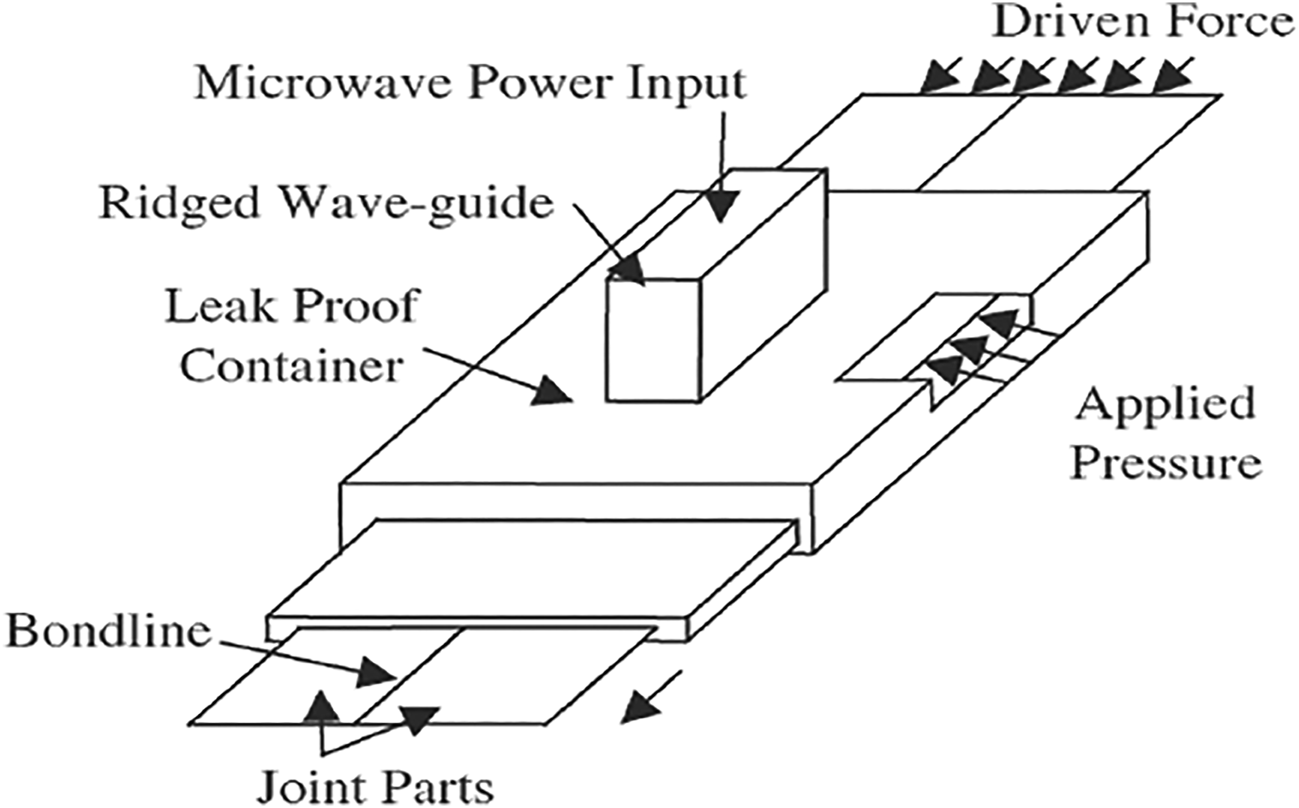
The microwave welding technique is still in the development stages and currently, there is no industrial application known in this regard but in the near future microwave, the weld may prove to be useful for joining automotive under-body components and aerospace parts. The schematic is shown in Figure 10. Microwave welding diagram.
69
Resistance welding
The resistance welding technique utilizes a conductive element, placed at the interface of components to be joined. This conductive element is usually a carbon fiber or a steel mesh and is connected to a power source. When electric current flows through this conductive element, heat is generated at the interface to melt the plastic and create a bond line.67,68 The schematic of resistance welding is illustrated in Figure 11. The most critical process parameter of resistance welding is the electrical connection between the heating element and power source. A proper connection between the two helps in introducing adequate current into the system to melt the plastic and form a bond line. Some commonly used approaches include clamping on the bare fibers, direct clamping on prepreg, dipping prepreg in liquid metal bath, clamping bare fibers painted with a silver-filled epoxy, etc. Schematic of the resistance welding process.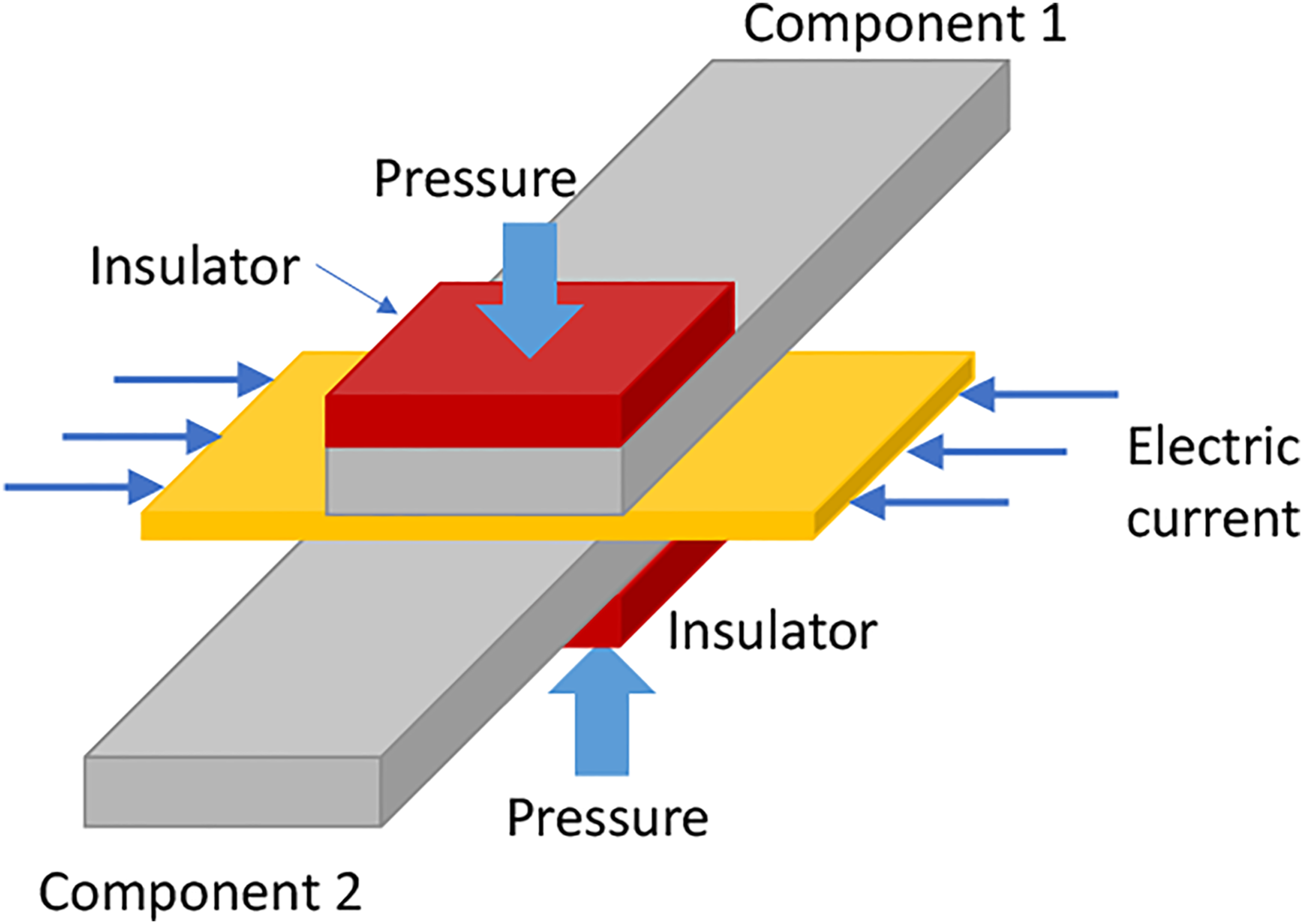
The welding can be carried out under either constant load or displacement control. A variant of this technique, called impulsive resistance welding supplies power in the form of intense pulses, instead of continuous power. It is a more energy-efficient approach, requiring lesser energy to melt the matrix due to fewer heat losses. Resistance welding is a promising technique for aerospace applications. The process is relatively quick (takes 1–4 min), requires a little amount of material, and can be easily used for large structures. Good thermal insulation and an accurate amount of input energy may reduce the welding time and enhance the joint quality.70–72
Howie et al. 73 determined the optimum parameters of resistance welding using a statistical approach. They prepared lap shear coupons using a dual-polymer material system and concluded that maximum joint strength was obtained for composites welded at temperatures above glass transition temperatures (Tg) of the polymer. A sequential resistance welding process is employed to join the large thermoplastic composite parts. It involves the division of the large weld into smaller segments which are then welded in sequence. In such a case, the critical issue is the process parameters required to achieve the desired thermal history. A 3D thermal analysis is done to find suitable process parameters, identify local overheating regions, and determine the factors influencing temperature uniformity at the welding interface.
Holmes, et al. 74 established a methodology to develop thermal models of the resistance welding process. They developed a one-dimensional model to get weld interface thermal history and thermal gradients data in the through-thickness direction. A two-dimensional model was used to generate thermal gradients along with the interface of the weld. Both these models provide a basis to investigate the three-dimensional thermal behavior of large components during sequential resistance welding. Jakobsen et al. 75 presented a transient thermal model for two-dimensional thermal analysis of thermoplastic composites joined by resistance welding. The localized heating and melt-through explained by this model were in agreement with experimental observations. Similarly, time to melt was also successfully predicted by the model and is successfully compared to experimental observations.
Don, Gillespie, and Lambing 76 studied the relationship between processing and performance of resistance welded graphite/PEEK composites. The processing parameters investigated included process time, initial pressure for consolidation, and rate of heat generation. The Mode I interlaminar fracture toughness and lap shear joints were developed under a constant displacement. They concluded that initial consolidation pressure has little influence on the lap shear strength of joints. The bond strength was found to increase with time in the melt for a given power level. The “time to melt” and “time in the melt” to achieve the desired strength, decrease with an increase in power level.
Hot plate welding
Hot plate welding is a thermal welding technique to join thermoplastic composites. This approach involves heating the polymer matrix composite pieces at their interface causing a decrease in viscosity. It results in the interdiffusion of polymer chains, as both surfaces are held together tightly (Figure 12). Slow cooling of the setup results in joint consolidation. The process is divided into three steps namely heating, joining, and cooling. The surfaces to be joined are brought into intimate contact (sometimes in quasi-contact) with a heating element (generally Teflon coated hot plate) to melt its interface. Adequate pressure is applied to ensure contact between the hot tool and the laminate (Figure 13). Excessive pressure will result in an insufficient amount of molten material on the surface, leading to poor joint strength. Macromolecular interdiffusion between two contacting parts.
77
Schematic of the hot plate welding process.
69
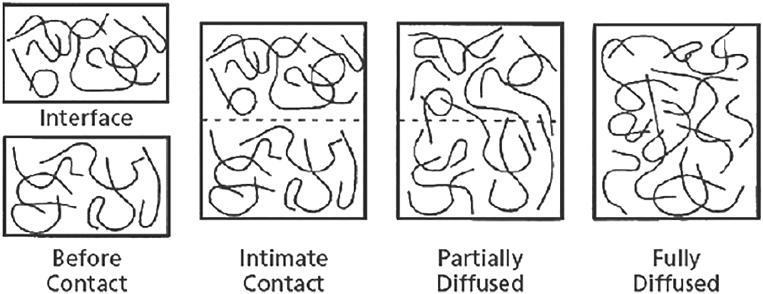
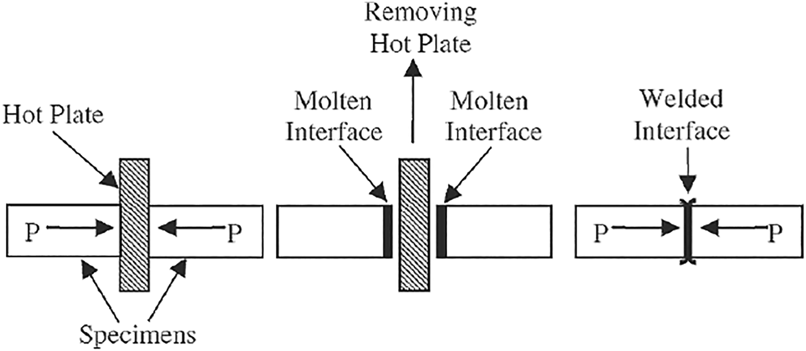
Mechanical stops are employed to prevent the squeezing out of the entire melt from the bond line, which leads to a “cold weld”. The pressure should be maintained until the thermoplastic matrix begins to soften and flow. Afterward, the hot element is removed, molten surfaces are pressed against each other, and allowed to cool until consolidation occurs. The welding of small parts is completed in 5–60 s approximately, while large parts may take up to 30 min. It is one of the most popular techniques to join thermoplastics because it is simple, reliable, and economical. However, there are chances of surface contamination and this is considered the main drawback of this technique.77,78
Radiant welding
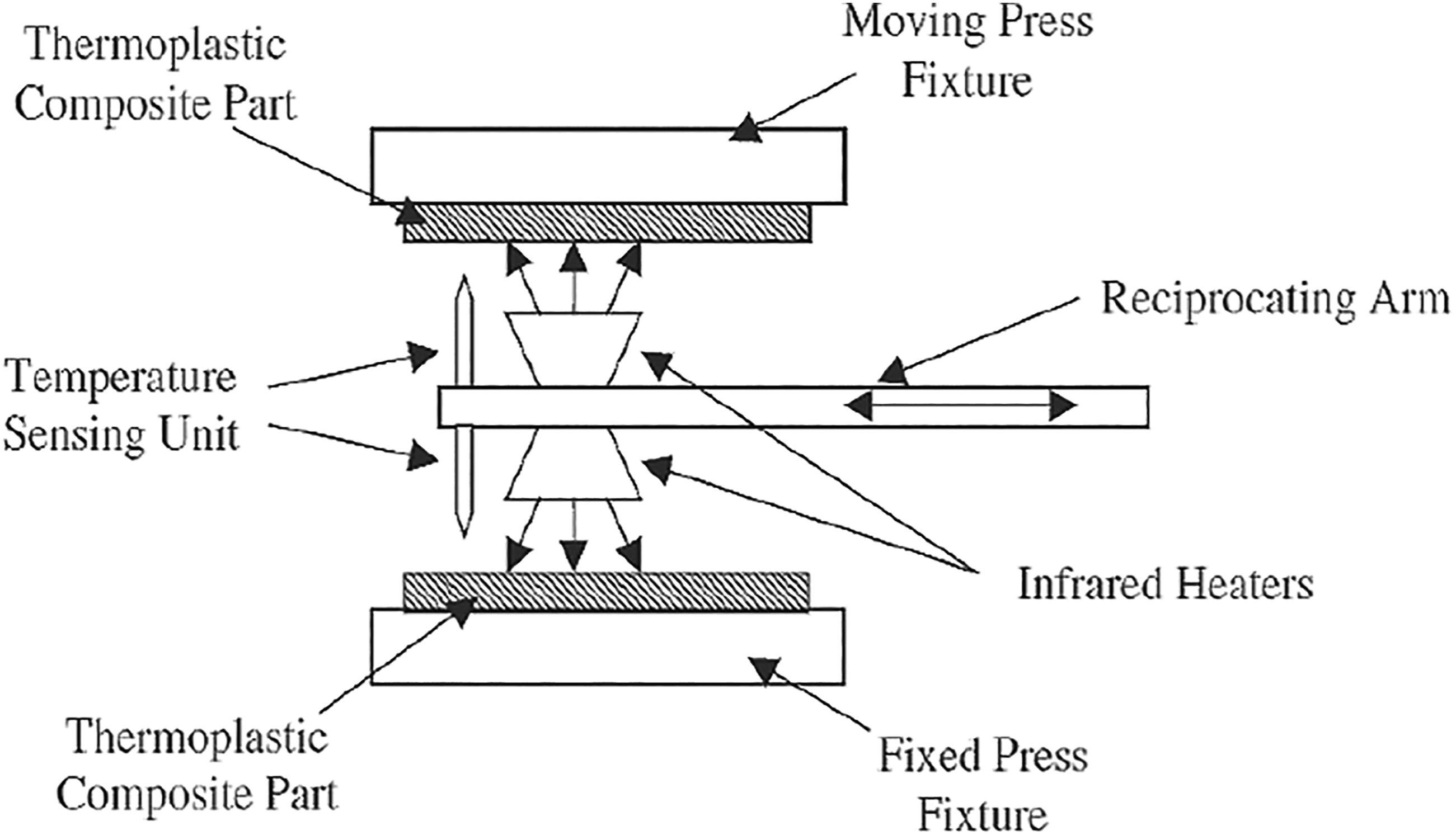
There are two variants of radiant welding, namely infrared welding, and laser welding. Infrared welding (IR) is a non-contact technique used for joining fiber-reinforced thermoplastic composites (Figure 14). The main advantages of IR sources are their ability to fast heating (typically 5 s) and reduced contamination risks. Therefore, this approach allows the processing of strong joints with high productivity and reproducibility. For instance, retention of 84% of polymer bulk strength has been reported for 20% in the volume of short glass fiber in the PES matrix.
79
A more consistent join with low scatters in mechanical properties results in high structural reliability as required in the aeronautical industry. The approach has high flexibility and the capability to join large flat and curved areas.79,80 The major limitation of this technique is the detrimental effect of pigments in changing polymer absorption properties thus reducing the product quality. The low energy transfer rate in darker polymers renders them more prone to surface degradation. Nevertheless, the deep heat penetration may be a concern due to possible laminate deconsolidation and warping during the heating stage, as well as the cooling stage.
81
Schematic of infrared welding system.
80
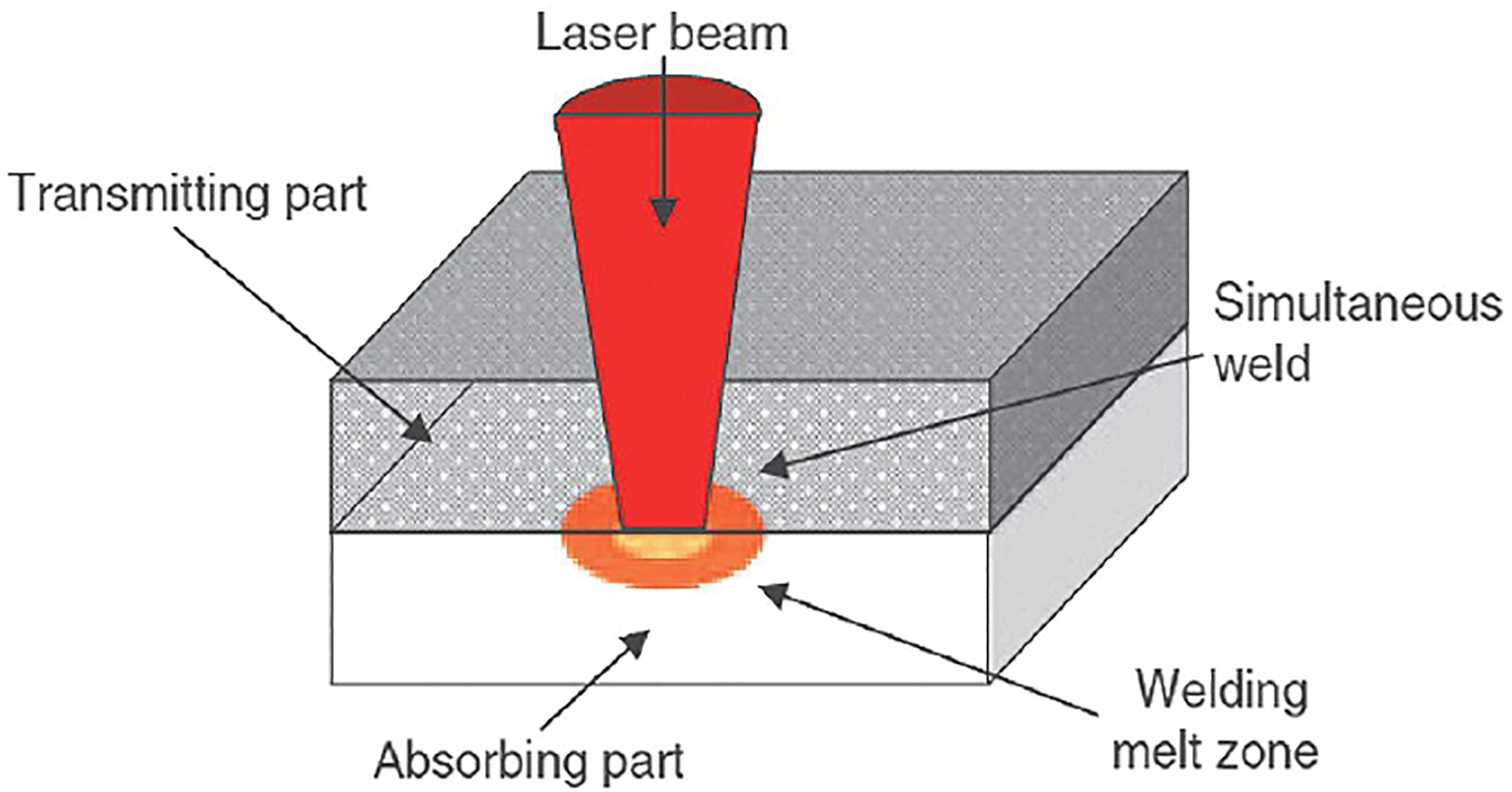
Laser beam welding (LBW) is a useful technique to join thermoplastic polymers-based components. It is considered an appropriate approach to joining thin, as well as medium to thick parts. Moreover, the size, geometrical requirements, and aeronautical parts specifications are more easily fulfilled by using LBW rather than other approaches.
82
A limiting factor in the practical application of this approach is that it allows the joining of thermoplastics if the top material is transmitting laser radiations and the bottom material is absorbing these radiations (Figure 15). Upon melting of both at the interface, fusion occurs, and both the components get welded. The LBW technology offers the flexibility of joining smaller components into a big part, ensuring full continuity. This approach is economical, helps in weight reduction, reduces the cycle time, and the bond strength is within the acceptable limit as well. But only a few studies reported the use of the LBW technique for structural applications. Therefore, the application of this technology for aeronautic parts still requires significant development and investigations.
82
Schematic of the laser beam welding (LBW) process.
82
Testing of composite joints
The properties of joints vary from the bulk material, due to confinement of strain and type of interaction with the substrate, either physical or chemical. Hence, it is necessary to carry out necessary tests to ensure joint safety. Both destructive and nondestructive test methods have been used to investigate the performance of composite joints. Visual inspection is commonly carried out before any nondestructive testing. It can recognize noticeable faults accessible to surfaces such as fiber breakages, edge delamination, and resin starvation. A very simple and oldest method of inspecting composite joints is the tap test. 83 For detection of debonding, the joints are lightly tapped with a tap hammer. 84
Ultrasonic testing (UT) is the non-destructive test most commonly carried out for composite joints. 85 It is very common in industries dealing with alloys and metals. With conventional systems, it was difficult to undertake ultrasonic testing in composites due to the higher attenuation caused by resin/reinforcement boundaries and anisotropic fiber/fabric which varies the speed of sound. The recent developments in the UT systems such as phased array and full matrix capture make it useful for composites inspection. Pulsed thermography is also a non-destructive test method that has been used for the identification of impact damage to adhesive joints. 86
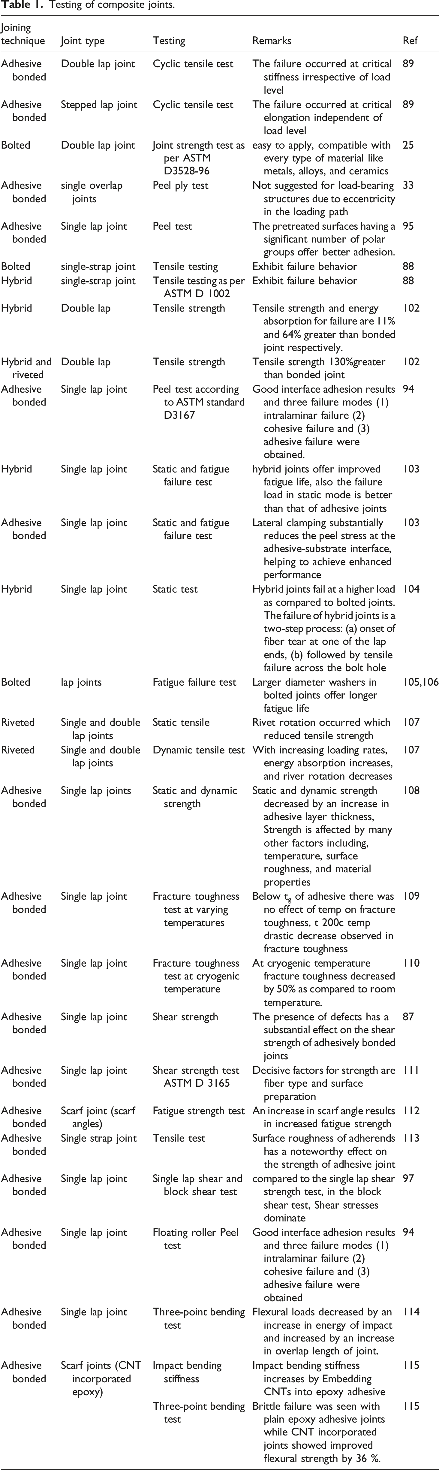
Testing of composite joints.
Strength characterization of adhesive joints is specifically performed by lap shear test and resistance to solvents is measured by wedge test.
90
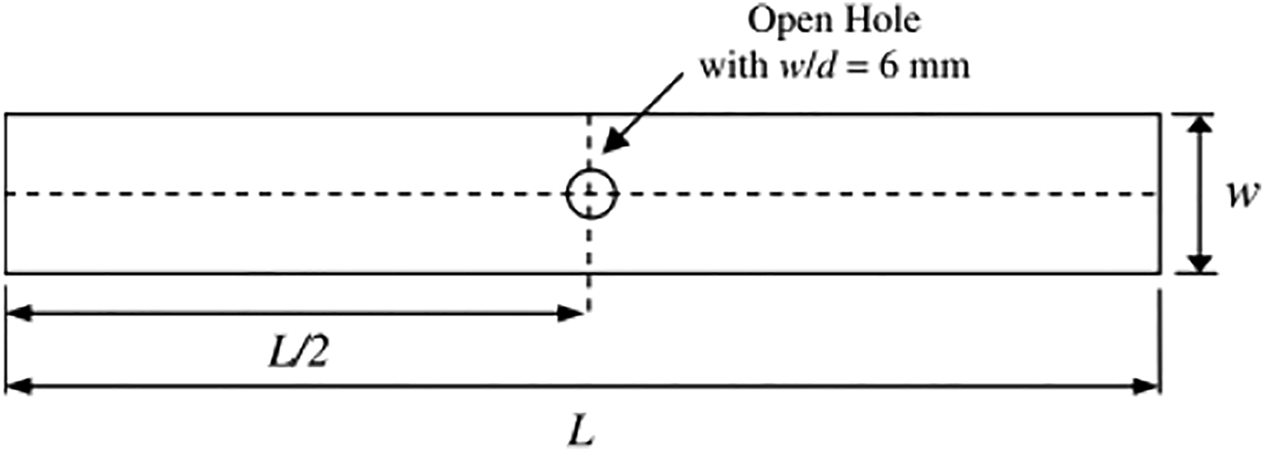
The notched tensile strength or open-hole tensile strength of bolted or riveted joints in polymer matrix composites can be determined by ASTM standard test method D 5766/5766M-02a whereas the compressive strength can be determined by following ASTM D 6484/6484M-04. Various factors such as specimen configuration, bolt hole preparation, and thickness scaling affect the ultimate tensile strength results. Thus, the following test specimen geometry is suggested (Figure 16); bolt hole diameter to thickness ratio range 1.5–3, width to bolt hole diameter ratio of 6, and edge distance to bolt hole diameter ratio of 3. Specimen geometry for open-hole tensile test of polymer matrix mechanical joints.
29
Voast 91 and Flinn 92 assessed the interface adhesion of composite bonded parts by a rapid test method. However, its limitation is the requirement of the hybrid bonded joint specimen. Riul et al. 93 compared the interlaminar strength of laminated composite joints by peel test. Sofia et al. 94 used the composite peel test (modification of floating roller peel test) to compare the interface adhesion of composites bonded with nine different adhesives at two different temperatures. This test method is used to investigate surface preparations and the strength of adhesives. Nick et al. 95 carried out a peel test on carbon fiber reinforced bonded composite joints, with four different adhesives at various temperatures. The Maximum adhesion strength was reported at the glass transition temperature. Adhesion strength was found to have a direct relationship with the no. of polar groups of adhesives at the bonded surface.
In literature single lap shear is among the most commonly used tests to study adhesion properties. It produces significant normal stresses (peeling forces) due to eccentricity in the load path. Delamination in composites bonded structures occurs due to normal stresses before adhesive bond failure.96,97 An alternate to this is the block shear test, which removes the eccentricity problem. The sample geometry of the block shear test is the same as the single lap shear test but shorter in length and contains thick adherends. 98 The typical test for fracture toughness characterization is the double cantilever beam (DCB) test. 90
Goglio et al. 99 determined the failure stress of a single lap joint under high-speed tensile loading of the adhesive assembly on the Charpy test machine. Yokoyama and his con author 100 conducted a test on butt joint hat-shaped specimens under dynamic loading using the Hopkinson pressure bar apparatus. They reported an increase in tensile strength and a decrease in energy dissipation of the adhesive joint at an increased strain rate. Adam et al. 101 conducted an impact bloc test to assess the fracture energy of the adhesive joint. He reported that fracture energy depends on test parameters and sample geometry. 14 Bisagni et al. 116 investigated the static and fatigue behavior of a single Lap shear joint on an MTS testing system under tensile loading.
Jen 113 carried out an experimental study to investigate the fatigue strength of scarf-bonded joints with various scarf angles. His results depicted a significant increase in fatigue life of bonded joints by increasing scarf angle. He also reported changes in the mode of failure by changing scarf angles such as at smaller scarf angle adhesive failure while a cohesive failure at large scarf angle. Stickler et al. 117 performed a bending test on stitched T-joint. Aymerich 118 investigated the static and fatigue performance of stitched single lap joints. Kwon JS. 119 followed ASTM D 638 to study tensile strength, modulus, and elongation properties of double lap adhesive joints. He also assessed the adhesive properties of double lap adhesive joints such as elasticity and plasticity and shear strength by following the standard method ASTM D 5656. Beams et al. 120 conducted static tensile and fatigue tests on bolted, adhesives, and hybrid joints and found that hybrid joints give the best performance as compared to adhesive and bolted joints. Franco et al. 121 also reported that compared to simple joints hybrid joints offer higher static strength and damage tolerance.
Comparison of different joining techniques
Mechanical joints are found to be advantageous to adhesive joints by various means such as, it offers ease in the procedures of assembling/disassembling parts, replacement, repairing of parts, airworthiness certification, inspection, and tolerance to environmental effects and higher joint strength.29,122–125 Adhesive joining requires proper surface treatment as well as the selection of adhesive material that can work with both metal and composites is a quite challenging task.126–128 Hence, despite the several drawbacks of the bolted joints, these are still used for composites. Following are the limitations of bolted joints.
In bolted joints, the fastener hole act as a weak spot promoting stress concentration, 129 breakage of the fiber’s continuity during the drilling operation, and crack initiation near drilled hole consequently reducing the load-carrying capacity of composite.127,130,131 Moreover, drilling holes induce undesirable damages (fiber pull out, micro-buckling and delamination) which reduces the fatigue resistance drastically, thus impairing the performance of the composite. 132 The fastener itself acts as a source of substantial weight increment. In the manufacturing ship and aircraft structure, the weight reduction strategy specifically focuses on the decrease of the number of fasteners.
Adhesive joints are advantageous in terms of weight reduction and cost-saving by using low gauge materials. 31 In the manufacture of the Dreamliner airplane Boeing 787, 50 % of composite materials were used in its structure using the adhesive joining technique. Many mechanical processes such as drilling, milling, and forming are eliminated or reduced. It requires a small binding force to prepare large bonding areas. Adhesive bonding joints offer improved visual appearance, smoothness, and electric and thermal insulation as compared to riveted or bolted joints. Adhesive joints offer corrosion resistance and better fatigue resistance as compared to bolted joints with identical elements. 133
Failure modes
Herein we can see a comparison between failure modes of adhesive and mechanical (bolted) joints. Bolted joints in composites undergo the following failure modes as29,124,134; shear out failure, net tension failure due to tension failure of fiber, and matrix failure at hole edge when width to diameter ratio becomes small, bearing failure due to compression failure of matrix and fiber, axial separation (shearing of fiber/matrix) and delamination around the hole edges (Figure 17). Delamination occurs by drilling composites by the following mechanisms: (a) peel up at the drill entrance and (b) push at the drill exit.135–137 Out of plain loading of composite structures also results in partial or full pull out of bolt.
29
From all these failure modes only bearing damage results in progressive failure, indicated by the non-linear behavior of the joint.124,131 According to Lim et al.,
138
failure modes depend on the stacking sequence of the composite joint. Turvey and Wang carried out an experimental study on single bolt tension joints and reported that failure modes depend on water immersion period and temperature, as specimens failed due to bearing failure by increasing temperature. Shaker et al.
139
showed that failure modes of composites are changed by the addition of fillers. Failure modes in mechanical joints.
23
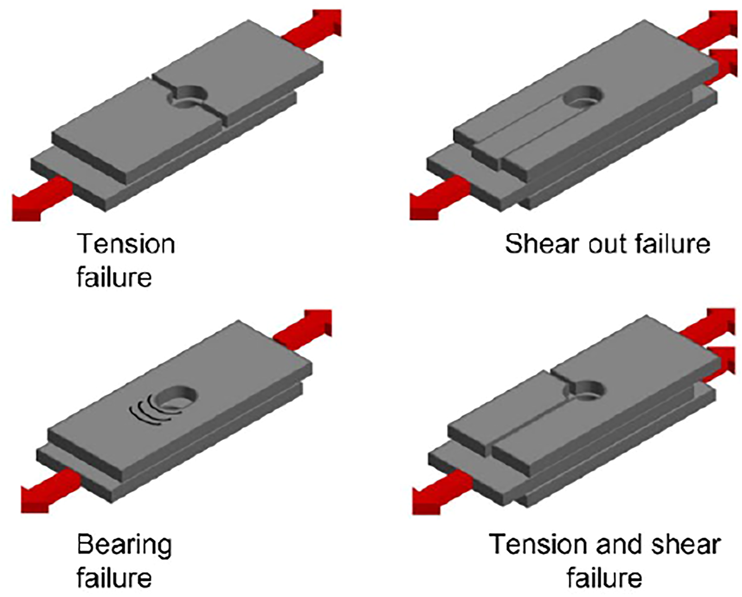
Shear out failure dominates in laminates with ample width compared to net tension mode but insufficient free edge distance at shear out the plane, due to which it cannot diminish the higher shear stresses. 134 Failures in bearing mode include fibers micro buckling, matrix cracking, and delamination.140,141 Soykok et al. 142 investigated the impact of aging by water on strength of glass/epoxy single lap shear joint at temperatures 50, 70, and 90°C. They reported that aging carried out at higher temperatures exhibited abrupt failure of the joint in net tension failure mode whereas, samples aged at a lower temperature of 50°C showed safe bearing failure mode. Sohon 143 investigated the failure modes of bolted composite joints subjected to fatigue loading.
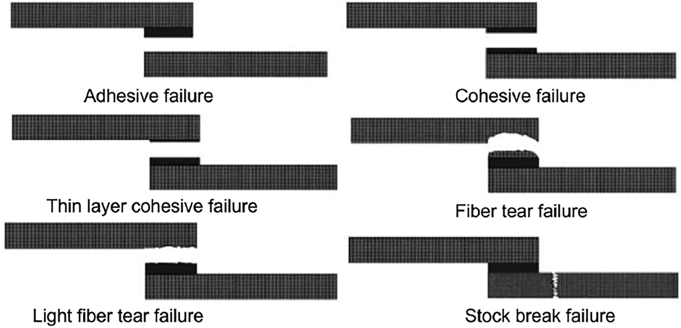
Many experimental studies described the effect of several parameters on failure modes of adhesively bonded joints in composites.144–151 Among those, the parameters dominating in their effect on failure behaviors are stacking sequence, surface conditions (pretreatment, abrasion, contamination), surface ply angle, bond-line thickness, fillet, and environmental conditions. According to ASTM D5573, the typical failure modes in fiber-reinforced polymer composites adhesive joints include stock break failure, light fiber tear failure, fiber tear failure, cohesive failure, adhesive failure, or mixed failure as shown in Figure 18.
151
The commencement of the several failure modes depends on the type of loading, geometric dimensions, and properties of the constituent materials (core, adhesive, and facing). Local delamination is a common failure mode of adhesively bonded joints for all types of loading conditions, which leads to the disastrous failure of composites bonded structures. Turaga and sun
152
investigated the failure mechanisms of T joints in composite sandwich structures. They figure out the corresponding failure modes as crack formation in the core of the sandwich and debonding of the sandwiched components. Failure modes in adhesively bonded joints.
31
As reported by Shenoi et al., 153 the failure modes in adhesive bonded composite T joints depend on the materials’ properties and geometric configuration. Another research group 154 identified shear failure of the core and interfacial debonding as the main failure modes of t joints under pull-out loading conditions.
Effect of environmental conditions
The performance of bolted joint structures is based on the consideration that these are operating under constant environmental conditions. But the fact is different as due to excellent stiffness to weight ratio composites are used as a primary structural material in the marine, transportation, defense, and modern aviation industries, where they experience various environmental conditions.
These applications involve diverse and sometimes adverse working environments. Parida et al. carried out an experimental investigation to study the effect of environmental conditions on the bearing strength of single lap and shear bolted double lap composite joints. The carbon fiber prepreg composites made of uni-directional and bi-directional satin weave and epoxy were subjected to hot and wet (relative humidity 85% and temperatures 70°C) environmental test conditions. At the ultimate failure point, a reduction of less than 20 % bearing strength was reported for woven fabric laminates whereas this value increases to 25–30 % for angle ply laminated composites.
Among the various environmental conditions, the effects of moisture/humidity and temperature need to be specifically investigated, as these parameters substantially impact the performance of polymer matrix composites.
155
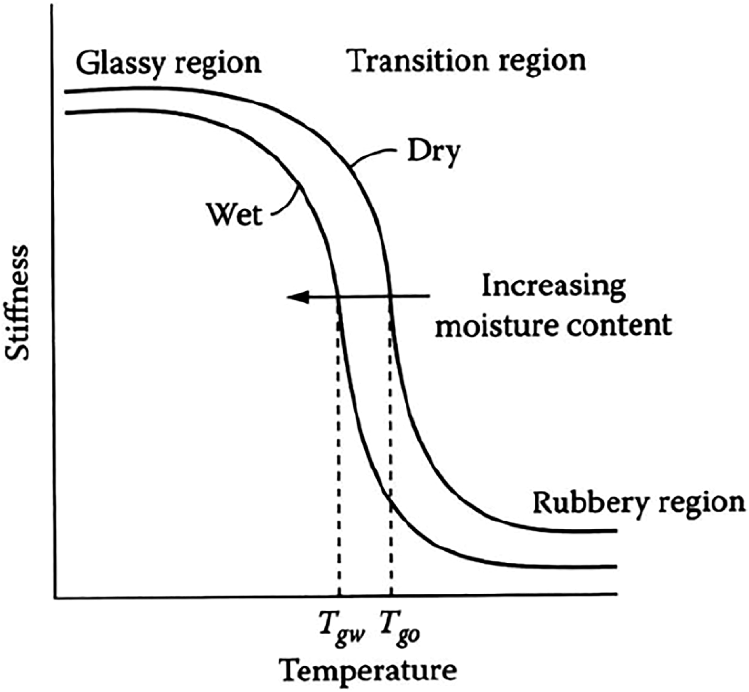
It has been found that a hot and humid environment adversely affects the strength of composite joints. The term “hygrothermal” is referred to the combined effect of temperature and humidity. The effect of the hygrothermal environment on the mechanical performance of polymer matrix composites is important from two aspects. An increase in temperature beyond the Tg of the polymer results in too softening of polymer that it can no longer be used as a structural material (Figure 19). Tgd represents the glass transition temperature of composite materials when dry, similarly, Tgw represents the glass transition temperature of the composite when it absorbs moisture. Change in moisture content and temperature results in differential shrinkage or swelling of the composite elements which consequently generates hygrothermal stresses and strains.
23
A bolted joint in a reusable launch vehicle when used in a cryogenic environment should be able to endure a low temperature of 129oC, or a very high temperature of 1290oC when used for the wing of an aircraft.
29
Stiffness of a composite material as a function of temperature.
23
During the service life of composite, they may experience various environmental conditions. As compared to bolted joints, the performance of adhesive joints is assumed to be more declined when exposed to harsh climate. Literature shows that adhesively bonded joint strength and fracture toughness with structural adhesive shows temperature dependency. This temperature-dependent behavior is mainly due to the low adhesive strength at higher temperatures, and higher brittleness and thermal stresses observed at low temperatures. Some studies also reported the Mode I,109,110 and Mode II fracture toughness 156 of adhesive bonded joints as a function of temperature. According to Melcher and Johnson’s 110 findings, at cryogenic temperature, fracture toughness decreased as compared to room temperature. Banea et al., also showed a temperature-dependent mode I fracture toughness of adhesive bonded joints over a wide range of temperatures (room temperature to 200oC). 157
Material selection
The fasteners used to join composite parts are categorized as non-metallic and metallic fasteners. The fasteners made of titanium, aluminum, steel, and stainless steel are commonly used. The selection of material for bolts, rivets, or pins depends on the following factors. (1) Fastener system weight (2) Thermal expansion coefficient of the fastener (3) Delamination (4) Galvanic corrosion of the joint by water between composite and fastener.
Apart from these, materials selection includes the type of reinforcement, geometric parameters, layup sequence, and resin matrix. Roman and Joakim have conferred the importance of some of the above-mentioned factors on bolted joints in polymer composites. 158 They concluded that an appropriate selection of materials and geometric paraments is very essential for the integrity of composite structures. The environment compatibility of the laminate material and fastener is of prime importance in the selection of metallic fasteners, to avoid galvanic corrosion. Hence, fasteners made of corrosion-resistant steel, nickel, titanium, and cobalt alloys are preferably used when joining carbon fiber reinforced composites.151,158,159 Fasteners made of low alloy steel, cadmium, magnesium, and aluminum are inappropriate with carbon fiber reinforced composites. For heavily loaded structures, metallic fasteners are the right choice however, for lightly loaded structures nonmetallic fasteners provide adequate strength. Nonmetallic fasteners made of thermoplastic or thermoset materials are also advantageous using corrosion-free nature and weight reduction.160,161
Adhesive bonded joint strength depends on the chemical and mechanical properties of adhesive and adherend materials. Thus, to achieve the maximum bond strength as required in industrial applications the choice of the adherends and adhesive material is imperative. Adhesive material properties can differ significantly, and a suitable choice is important for an appropriate joint design. So, it is essential to depict the adhesive behavior to identify its mechanical properties (modulus and stress-strain values) in a variety of adhesive joint configurations. 162 To investigate adhesive properties, a variety of specimens and test geometries are used.
The selection of the adhesive material depends on many factors including, the nature and type of the substrate to be bonded, a form of adhesive (liquid, paste, film, one-part, etc.), expected in-service environment for example temperature, mechanical performance required for adhesive joint for example shear strength, extension, the cure method, required open-time before cure, the special property required - for example, electrical, thermal, and optical, acceptable for site health and safety policies and sometimes the selection of the adhesive material depends on the cost of adhesive in a certain production condition. The selection of the adhesive material depends on many factors including,23,31,142: • Nature and type of the substrate to be bonded, • Form of adhesive (liquid, paste, film, one-part, etc.), • Expected in-service environment (temperature, humidity, etc.) • Mechanical performance required for adhesive joint (shear strength, extension, etc.) • Cure method, required open time before cure, • Any specific property requirement (electrical, thermal, optical, etc.), • Acceptability for site health and safety policies, • Cost of adhesive
For structural applications, adhesive materials include acrylics, silicones, epoxies, polyurethanes, and high-temperature adhesives such as bismaleimides, polyamides, and phenolics.23,31 Some studies in the literature 33 reported a decline in joint strength of thermoplastic composites as compared to thermosetting composites when using epoxy and acrylics as adhesives. This is the consequence of the lack of adhesion of the adhesives with thermoplastic composites.
Conclusions
The review concludes that no single joining technique is suitable for all the application areas. Each joining method has its pros and cons, and the selection of the joining technique depends upon end application and specific design requirements. Adhesive bonding is commonly favored over mechanical joining considering the load transmission capability and uniform joint that preserves structural integrity can be accomplished at a low cost with the reduced weight of the assembly. However, the design engineers and researchers still lack to predict the performance of adhesive joint even after it passes laboratory testing. Fusion bonding techniques such as ultrasonic, induction, and resistant welding shows great potential for volume-intensive application, such as wind turbine blades, automotive, aerospace fuselage, bulkhead, and surfboards, where short processing cycles are necessary. Advantages of these methods over other joining techniques are fewer surface preparation requirements, recyclability, reprocessing, and improved integrity/durability. Process integration is a basic part of the joining procedure. Specific necessities of each joining method ought to be examined in design codes, to coordinate these prerequisites at the beginning phase of the design process.
Among various joint configurations scarf joints are considered more efficient due to flat stress distribution. Although single lap joints and double lap joints are considered less efficient due to their ease in fabrication and simplicity, these are still widely used in aircraft structures. It is well known that the failure of composite structures generally occurs within joining areas of components. In naval applications, composites structures may be subjected to higher loading rates. Many studies cited above are performed on composite joints under quasi-static conditions. Few studies have been reported on the dynamic behavior of composite joints. Hence, more in-depth investigations on the dynamic response of composite joints at various strain rates are required.
Footnotes
Declaration of conflicting interests
The author(s) declared no potential conflicts of interest with respect to the research, authorship, and/or publication of this article.
Funding
The author(s) received no financial support for the research, authorship, and/or publication of this article.