
Abstract
Honey Comb Sandwich Structures (HCSS) have numerous applications in aerospace, automobile, and satellite industry because of their properties like high strength to weight ratio, stiffness and impact strength. Fused Deposition Modeling (FDM) is a process which, through its flexibility, simple processing, short manufacturing time, competitive prices and freedom of design, has an ability to enhance the functionality of HCSS. This paper investigates the mechanical behavior (i.e. flexural, edgewise compression and Interfacial bond strength) of FDM-built HCSS. The influence of face/core material was examined by manufacturing four types of specimens namely ABS core with Composite (PLA + 15% carbon fibers) face sheets, ABS core with PLA face sheets, TPU core with composite face sheets and TPU core with PLA face sheets. To measure the effect of face sheets geometry, raster layup was varied at 0°/90° and 45°/−45°. The mechanical characterization revealed that an optimum combination of materials is ABS core with composite face sheets having raster layup of 0°/90°. This study indicates that HCSS with complex lamination schemes and adequate mechanical properties could be manufactured using FDM which may widen the applications of FDM on an industrial scale.
Keywords
Introduction
3D printing or Rapid prototyping (RP) technology was invented in the 1970s and since then, it has created a revolution in the manufacturing industry. RP can be defined as the technology which can construct a 3D physical model from a computer-aided design data. The applications of 3D printing ranges from large scale like complete 3D printed car was launched in 2011 1 to a lot of micro scale applications which can be seen in Hasan et al. 2 The most commercialized RP technique today is Fused Deposition Modeling (FDM). Extraordinary applications of FDM have been achieved in the fields of tissue engineering and medicine.3–9 In 2008, a customized leg was printed by FDM, consisting of parts that do not require assembly i.e. including the knee, foot, and socket. Besides biomedical applications, FDM has found applications in jigs, fixtures, check gauges and aircraft parts using high-performance thermoplastics like ULTEM 9085. Continuous breakthroughs are still going on.
In this process, the whole model is divided into a number of layers which are later printed one by one. In FDM process, thermoplastic (filaments) are used as a starting material. Filaments are heated in the nozzle and are then dispensed on the printing plate layer-by-layer to produce the desired 3D structure.
At present, FDM is being used for building prototypes for small scale production. However, research is being done for the past few years to employ FDM in manufacturing real-world structures that are expected to bear lesser mechanical stresses, like Unmanned Air Vehicles (UAV). Brischetto et al. 10 manufactured an inexpensive multirotor UAV called PoliDrone, for which all the structural elements were fabricated with polymers using FDM technology. They also recommended that the weight of the structural elements of UAV can be further decreased by using honeycomb sandwich structures manufactured by FDM. Goh et al. 11 also suggested that using FDM-built HCSS can enhance the performance of UAV in terms of shorter take off time and longer flight endurance. Brischetto et al. 12 presented a preliminary evaluation of the flexural properties of FDM-built HCSS manufactured by varying the material of core and face sheets as PLA and ABS and employing two types of assemblies i.e. single extruder assembly and double extruder assembly. They established that the supreme mechanical properties were exhibited by the specimens having core and face sheets both of PLA and manufactured with single extruder assembly. Pollard et al. 13 fabricated honeycomb cores with FDM and evaluated the effect of printing parameters on the flatwise compressive strength of FDM-built HCSS. It was reported that the thick-walled specimens behaved more ductile than the thin-walled specimens. They also revealed that FDM honeycombs have low cost than traditionally used Nomex honeycombs. FDM-built HCSS having adequate mechanical properties, low cost and reduced weight could be employed in aerospace and automotive applications, which is the motivation of this research. However, to accomplish this task a comprehensive knowledge and detailed systematic investigation is required. Nevertheless, to the best knowledge of authors, only a basic level research is available in the literature on the FDM-built HCSS.
To begin with, it is identified that FDM-built HCSS found in literature are manufactured using only basic polymer materials such as ABS and PLA. However, a lot of new high-performance FDM filaments are available nowadays. Like, there is a trend to use composite filament in order to enhance the performance of FDM printed structures.14–22 Zhong et al. 16 added short glass fibers with ABS to overcome the deficiencies in the mechanical properties of ABS like low strength. It was observed that the strength of ABS is improved but it became difficult to print and its flexibility decreased. Hwang et al. 23 prepared composite filaments by adding copper and iron particles to ABS filament and reported that by increasing the metal content, tensile strength was reduced but thermal conductivity was enhanced. Hassan and Jwu 17 did further investigations by conducting tensile, flexural and impact tests on ABS mixed with Polycarbonate (PC). It was found that tensile, flexural and impact strength increased by increasing PC content but creep resistance decreased. Hence, it was revealed from these studies that the properties of FDM parts are considerably improved if they are fabricated with filaments incorporated with either carbon/glass fibers or metallic particles. Correspondingly, it is expected that the mechanical properties of FDM-built HCSS may also enhance if composite filament (i.e., PLA with carbon fibers) is used as the printing material, which is not examined to date.
The printing parameters of FDM process (i.e. Wall thicknesses, Air gap, Built orientation, Printing temperature, manufacturing speeds, Raster angle, Fill density and Nozzle diameter) have a significant effect on the mechanical properties of printed parts.16,23–30 Among which, particularly for the case of FDM-built HCSS, the effect of only two printing parameters (i.e., manufacturing speeds, wall thicknesses) has been studied till now.12,13 Therefore, to deepen the knowledge on FDM-built HCSS, the effect of the raster angle on their mechanical properties is essential to be studied. Since, raster angle (the angle between the path of the nozzle and the X-axis of the printing platform) was found to be a key parameter to affect the mechanical properties of FDM parts.23,31
The mechanical properties of FDM-built HCSS have been evaluated just under flexural 12 and flatwise compressive loads. 13 Yet, there are several other properties, like, edgewise compressive strength and interfacial bond strength which are very crucial to be considered. It was reported that the edgewise compressive strength of sandwich structures provides the basis for the assessment of the load-carrying capacity, 32 and interfacial bond strength is a dominating factor in determining the mechanical strength of FDM components. 33
The present study addresses the above mentioned gaps in the literature and was carried out by considering the following points. The fabrication of FDM-built HCSS was carried out by varying the material type and raster angle. Materials used were Acrylonitrile butadiene styrene (ABS), Thermoplastic polyurethane (TPU), Polylactic acid (PLA) and Composite (PLA + 15% carbon fibers). Four types of specimens were manufactured namely ABS core with composite face sheets (ABS-C), ABS core with PLA face sheets (ABS-P), TPU core with composite face sheets (TPU-C) and TPU core with PLA face sheets (TPU-P). The mechanical performance was examined by performing flexural, edgewise compression and interfacial bond strength tests. The failure modes of all three characterization tests were evaluated, followed by conclusions and further work.
Methodology
Honeycomb design
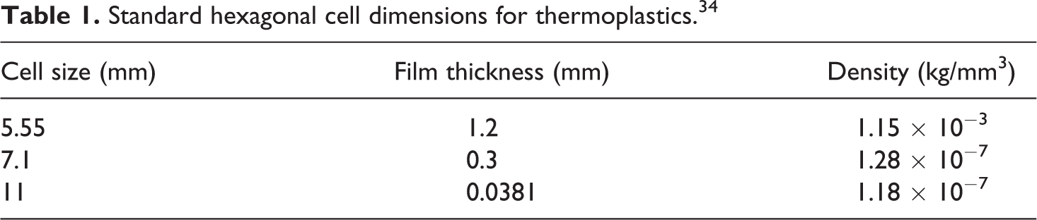
The nomenclature for hexagonal cell i.e. cell size, cell wall thickness, and cell height etc. are presented in the Figure 1, and their standard dimensions are given in the Table 1. Since, too thin cell wall thickness can cause difficulties in printing and can distort the part, therefore, the cell wall thickness should be such that it is easily printable by the FDM machine. Hence, from Table 1, the smallest cell size was selected so that the cell wall thickness was thick enough to be printed easily. The selected dimensions were: Cell Size = 5.50 mm, Cell wall thickness = 1.2 mm, Density = 115.3 kg/m3.
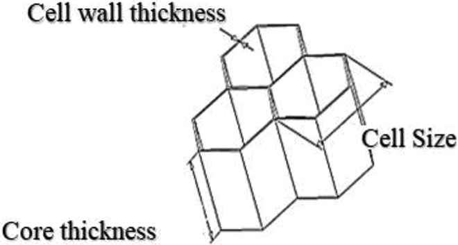
Nomenclature of honeycomb cell.
Standard hexagonal cell dimensions for thermoplastics. 34
Experimental plan
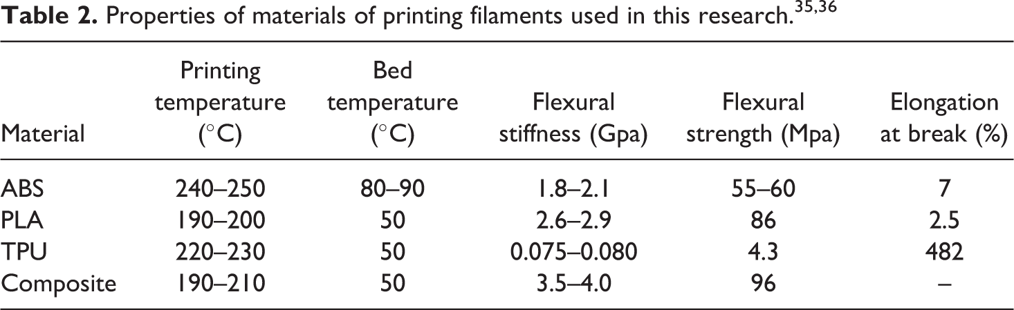
The main aim of this research was to fabricate HCSS through FDM and analyze the influence of varying the face sheets geometry (i.e. Raster Angle) and the materials of face/core on their mechanical properties like flexural, edgewise compression and interfacial bond strength between core and face sheets. The printing filaments of four different material were selected, namely ABS, PLA, TPU and Composite (PLA + 15% carbon fibers). The physical and mechanical properties of these filaments are listed in the Table 2. These materials offer a range of properties to incorporate in the HCSS. PLA (a biodegradable material) and ABS are easily printable materials with good mechanical properties. TPU, regarded as flexible material, can endure very high plastic deformation before failure as compared to what PLA and ABS can withstand. It possess excellent vibration damping and impact resistance properties which are basic requirement of sandwich structures. The composite filament was chosen because it has carbon fibers embedded in PLA thus providing strength to the plastic matrix and making it stiff, to be used as a face sheet in the honeycomb structure. The diameter of all the filaments was 1.75 mm.
For the fabrication of sandwich, the two materials with higher flexural modulus were chosen for the face sheet (i.e., PLA & Composite) and the other two were selected as the core materials (i.e., TPU & ABS). This resulted in following four combinations of HCSS: (1) ABS core with composite face sheets (ABS-C), (2) ABS core with PLA face sheets (ABS-P), (3) TPU core with composite face sheets (TPU-C), and (4) TPU core with PLA face sheets (TPU-P).
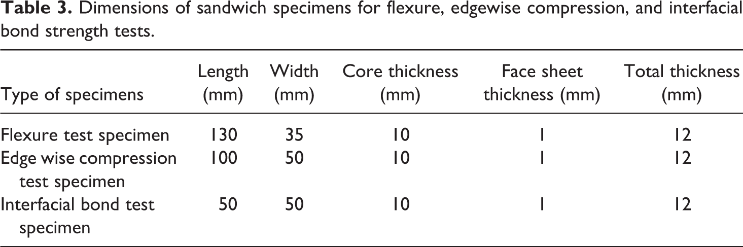
In most of the instances, HCSSs experience bending and compressive loads. Interfacial bond strength also plays an important factor in the evaluation of their strength, durability and damage tolerance. Therefore, three-point bending test, edgewise compression test and bond strength test were used to evaluate these properties as shown in the flow chart of the experimental plan in Figure 2. In view of this, three kinds of specimens were made against each combination of materials mentioned above, (1) Flexural specimens, (2) Edge wise compression specimens, and (3) Bond strength test specimens. The dimensions of all three types of specimens are given in Table 3.
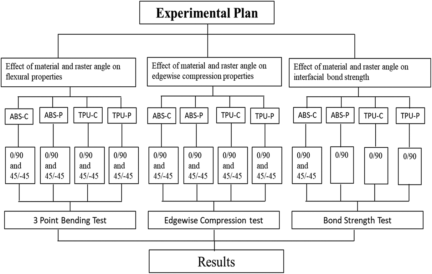
Flow chart of the experimental plan.
Dimensions of sandwich specimens for flexure, edgewise compression, and interfacial bond strength tests.
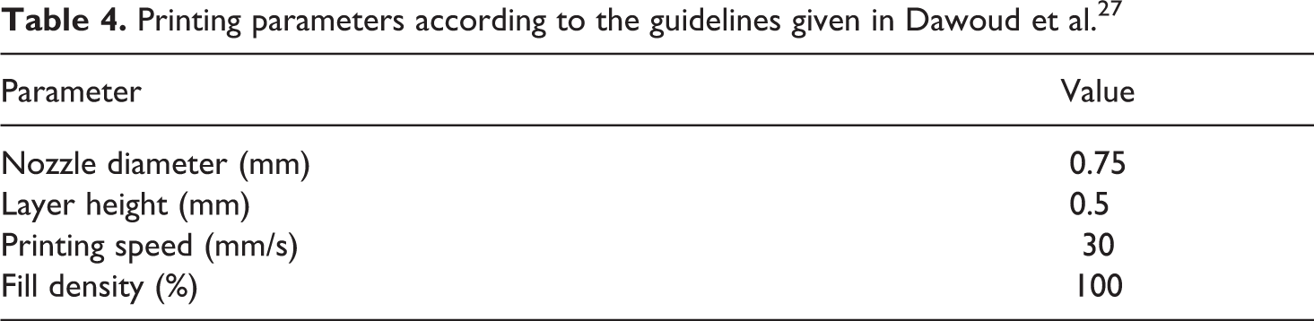
To explore the effect of raster angle, all the above mentioned four combinations were fabricated using crisscross raster layups of 45°/−45° and 0°/90°. Only these two raster angle combinations were considered because they have been found to show better performance than other possible unidirectional and crisscross raster angles (i.e., 30°/60°, 15°/75°, 0°, 90° etc.). 27 However, it was forecasted that the specimens printed with raster angles of 45°/−45° and 0°/90° would give the same interfacial bond strength as the specimens are going to be pulled apart in this test as shown in Figure 4(c), and the force perpendicular to the surface will have the same effect on 45°/−45° and 0°/90° raster angle specimens. Therefore, to validate this supposition, the raster angle was varied only for one type of combination i.e. ABS-C and was kept fixed to 0°/90° for all other combinations. Layer thickness and shell thickness were not investigated because they have been reported to not have a very significant effect on flexural properties. 24 Infill density was dropped from the investigation because of limited material and resources. The other parameters were kept fixed as listed in Table 4, which were chosen as best practice in FDM. 27
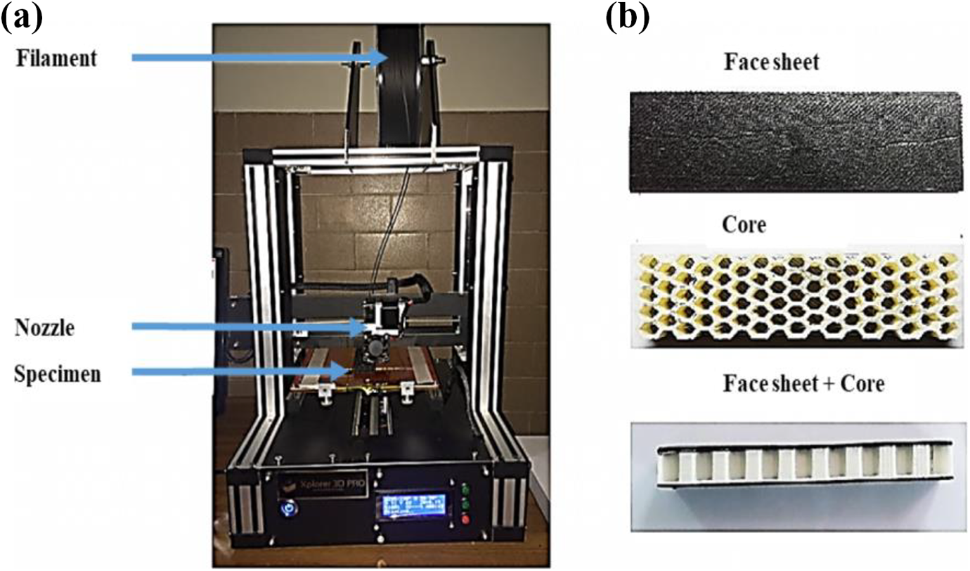
(a) X-Pro 3D printer and (b) exploded view of the sandwich panel.
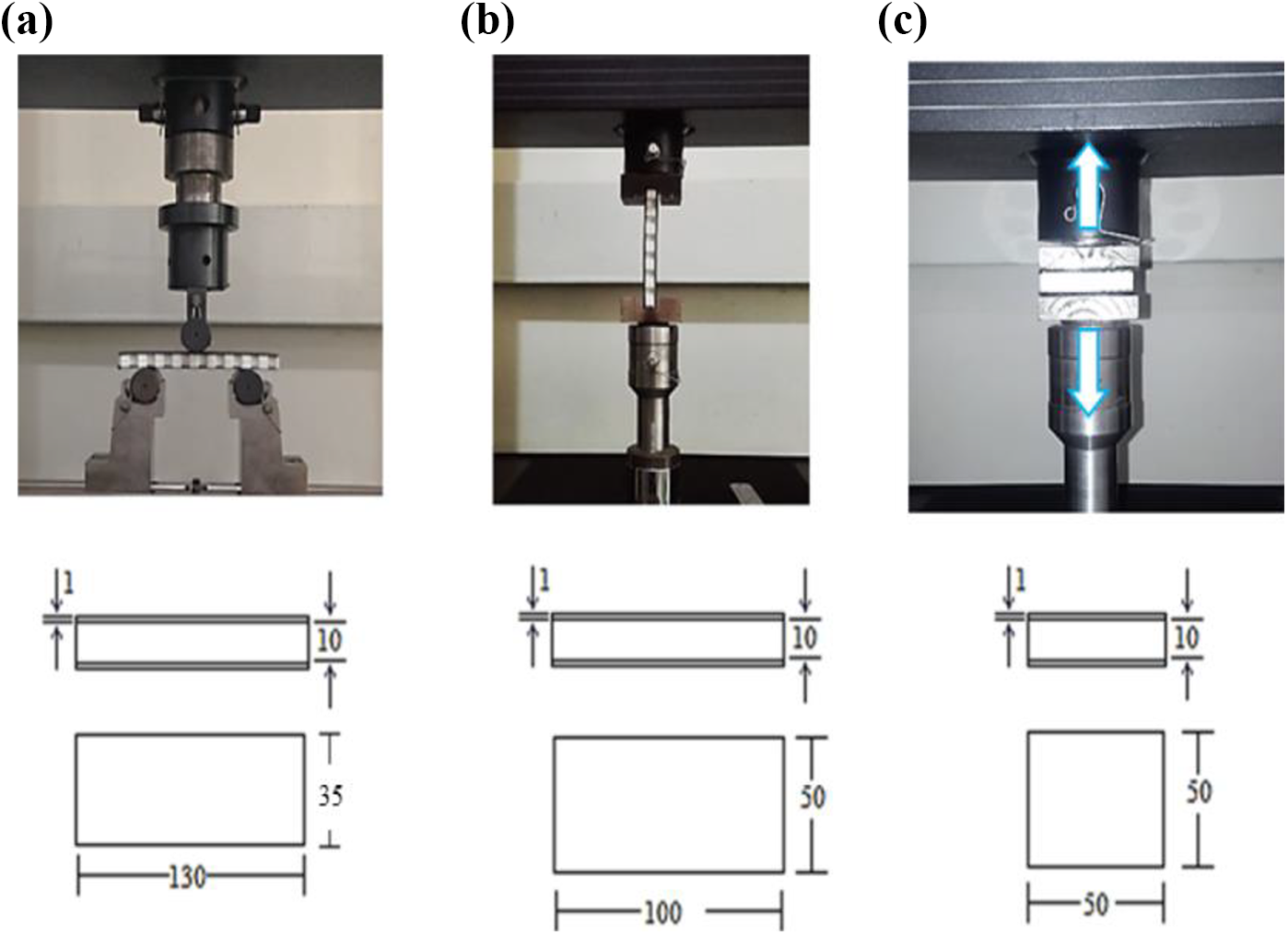
(a) 3-point bending test, (b) edgewise compression test, and (c) bond strength test.
Printing parameters according to the guidelines given in Dawoud et al. 27
Printing of specimens
In this study, specimens were made from a 3D printer in a continuous manufacturing manner. The “3D X pro” printer made by XPlorer 3D, Inc. was employed for the fabrication as shown in Figure 3. The printer operates like a robotic hot glue gun, in which filament is heated and pushed through a nozzle in a thin stream, and subsequently accumulated in layers as the platform descends. The model of the specimen was made on CREO software and STL file was loaded on a 3D printer. STL is a file format that combines 3D systems to describe face geometry, periphery and internal structures of a three-dimensional object without color or texture, it is extensively used in additive manufacturing and 3D printing systems. Figure 3 shows the exploded view of a representative honeycomb sandwich panel manufactured using FDM 3D printer. To consider the noise effect, two specimens were produced against each printing condition. Total of 48 specimens was printed in this research.
Test methods
After fabricating the required number of specimens, three types of mechanical tests were conducted i.e. three-point bending test for determining the flexural properties of honeycomb structure, edgewise compression test for determining compression strength along edges and bond strength test for determining interfacial bond strength between core and face sheets, according to ASTM C393-00, C297-16, and C364-99 standards, respectively. Overall, three types of geometries corresponding to three types of tests were employed in this work as shown in Figure 4. Each specimen was positioned in an Instron UTM 5567 tensile test machine and load was applied at a rate of 0.5 mm/min. Loading was continued until the failure of specimens and load-displacement data was recorded using which stress strain curves were drawn. All tests were conducted at room temperature (approximately 23°C). Each test was repeated twice in order to account for variations, if any. More than two were not possible because of limited resources.
Flexural properties i.e. core shear ultimate stress τ (Mpa), face sheet bending stress σ (Mpa), sandwich beam deflection Δ (mm) and flexural stiffness Ef (N/mm) were calculated from three-point bending test and using equations (1) to (4), respectively. Peak stress endured by specimens in the bond strength test was considered as interfacial bond strength between the core and face sheets.
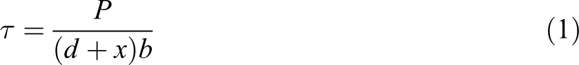
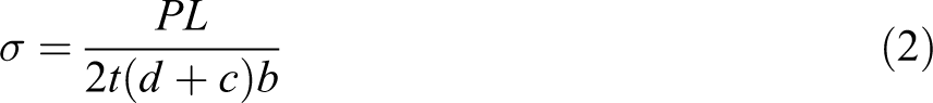


where d = sandwich thickness (mm), c = core thickness (mm), b = sandwich width (mm), t = face sheet thickness (mm) as shown in Figure 5.
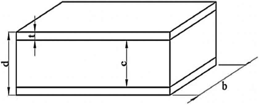
Sandwich panel dimensions.
While, P = peak load (N), L = span length (mm) in three-point bending test = 80 mm, G = core shear modulus (Mpa), D = panel bending stiffness, and U = panel shear rigidity
Results
Mechanical behavior of printed structures under bending load
Figure 6 depicts the stress-strain behavior of FDM-built HCSS under three-point bending load. Analyzing the curves, it was found that regardless of the fabrication conditions (i.e., material type and raster angle), all the specimens exhibited initially a linear trend and after approaching the peak value of stress, a downfall in the curves was observed which dictated beginning of delamination of face sheets as shown in Figure 7. The downfall was abrupt for the case of ABS-C and TPU-C specimens having composite material (PLA + Carbon fiber) face sheets and gradual for ABS-P and TPU-P specimens having PLA face sheets. This behavior can be associated to the brittle nature of composite face sheets, since carbon fibers are embedded in it.
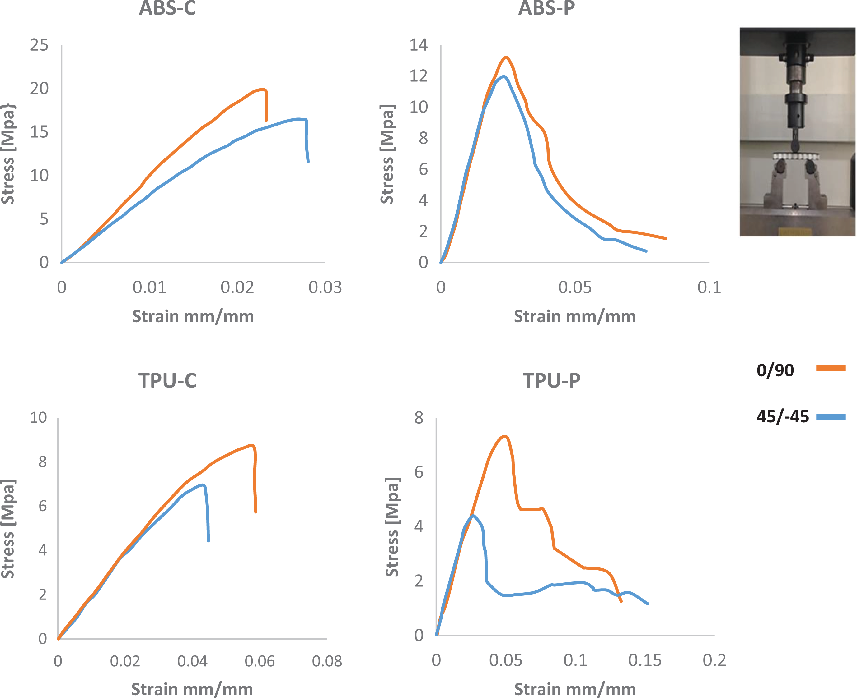
Stress–strain behavior of printed structures under bending load.
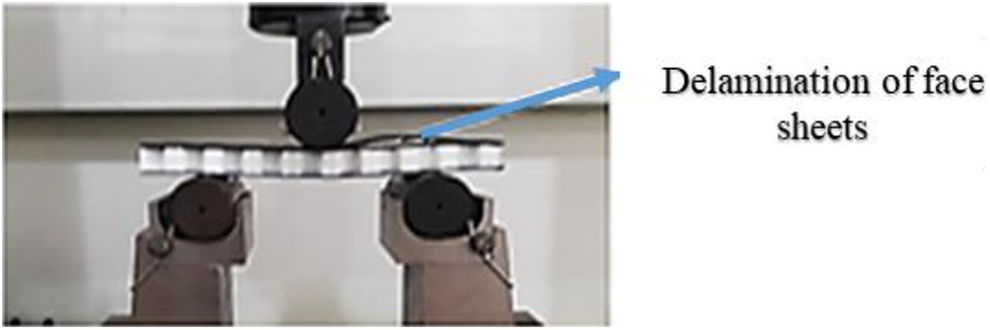
Failure during flexural testing.
The effect of the material on maximum stress sustained by the structure can be seen from Figure 8. It becomes evident that sandwich specimens built using ABS core with composite face sheets (ABS-C) exhibit the maximum capability to withstand the bending loads. While the structure with TPU core and PLA face sheets (TPU-P) experience the minimum flexural loads before failure. This trend might be due to varying bond strength between different laminates. This point will be further explained and ascertained in section 3.3. Moreover, comparing the peak stresses of FDM samples printed at 0°/90° and 45°/−45° raster angles, it was found that the specimens printed with 0°/90° raster angle withstood higher stresses than 45°/−45° raster specimens which is in agreement with. 24
Comparison of maximum stress endured by FDM-built HCSS under three points bending load.
Further, if the specimens having the same core materials are compared in Figure 8, it is found that specimens having composite face sheets (i.e. CPLA) endure higher stresses before failure than those specimens having PLA face sheets. In order to clarify this point, the SEM image of the fractured surface of the CPLA printed specimens are presented in the Figure 9. It was observed from Figure 9 as well as ascertained from the literature 37 that in the microstructure of the FDM printed CPLA samples, the short carbon fibers, stay highly oriented with the material deposition direction (i.e. raster layups). Therefore, it can be believed that the carbon fibers being exactly aligned with the raster layups is working as a major element in making the FDM specimens with the CPLA face sheets (i.e. ABS-C and TPU-C) significantly stronger than the specimens with the PLA face sheets (i.e. ABS-P and TPU-P).
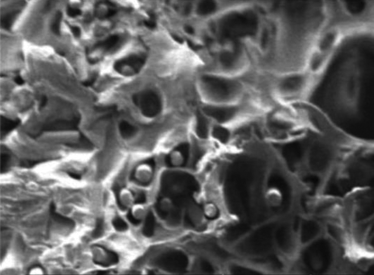
SEM image of CPLA fractured surfaces.
Further, it is also established that the material and raster angle have combined (or interactive) effect on the flexural strength of the HCSS. Hence, the mechanical properties of FDM-built HCSS could be controlled by selecting the suitable fabrication conditions (i.e. Material type and Raster angle).
In order to know the stresses endured by the core and face corresponding to delamination failure of structures, estimations were made using the respective peaks loads (i.e., load at which delamination failure observed in the HCSS) and above list equations (1) and (2). The results are shown in Figure 10. According to the results, ABS-C specimens sustained the highest core shear stress before failure, while TPU-P experienced the lowest. Similar results were observed for the face sheet bending stress. These results endorse the above finding that ABS-C specimens having the raster layups of 0°/90° exhibit the best performance under the bending loads.
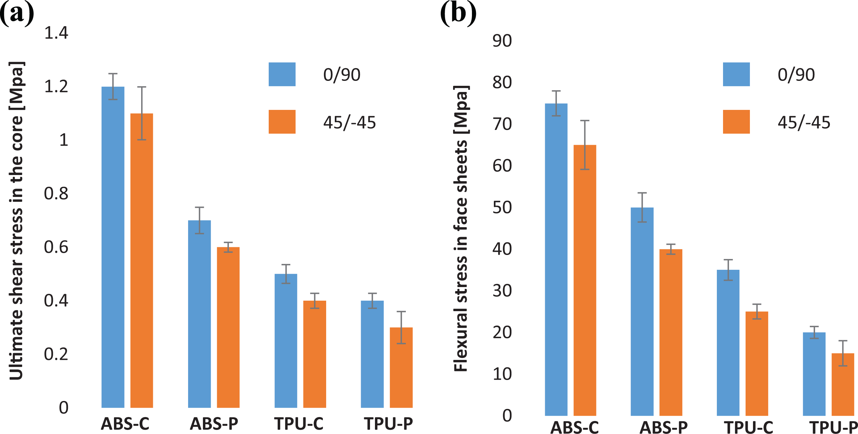
Effect of material and raster angle on (a) shear stress in the core and (b) bending stress in face sheets.
This is to note that Figure 10 report the stresses that the face and core endured at the loads that caused delamination failure in the structure. To estimate their respective ultimate values (i.e., core shear strength and face bending strength), one needs to change the span size to generate the required failure. However, the authors have examined that delamination was the main failure mode in the presently printed structures. Therefore, it seems that changing span might not much affect the type of failure. Therefore, work in this direction was not performed herein study. However, to further ascertain this point, testing is proposed in future.
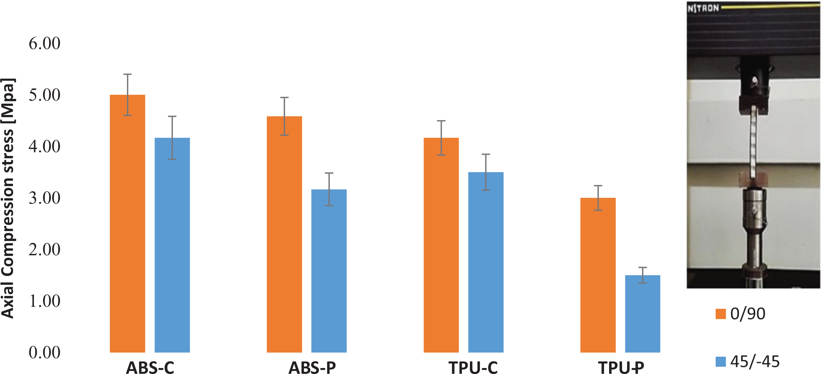
As structures were built layer by layer in FDM, this manner might affect the bulk properties of the material. Therefore, in order to examine if the FDM printing had completely translated the constituent material properties into structure, flexural stiffness was determined experimentally (from Figure 6) and analytically following the procedure reported in the literature. 38 The calculations were performed for two representative structures (best ones) namely ABS-C and ABS-P. As presented in Table 5, experimental stiffness is lesser than analytical stiffness (36–46%) thereby signifying that the printing technology could not completely translate the properties. This may be improved by post-heating. 4 However, this work is beyond scope of the present study.
Comparison of analytical and experimental flexural stiffness of HCSS.
Mechanical behavior of printed structures under bending load
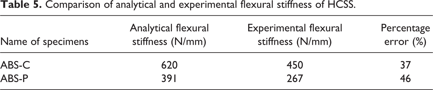
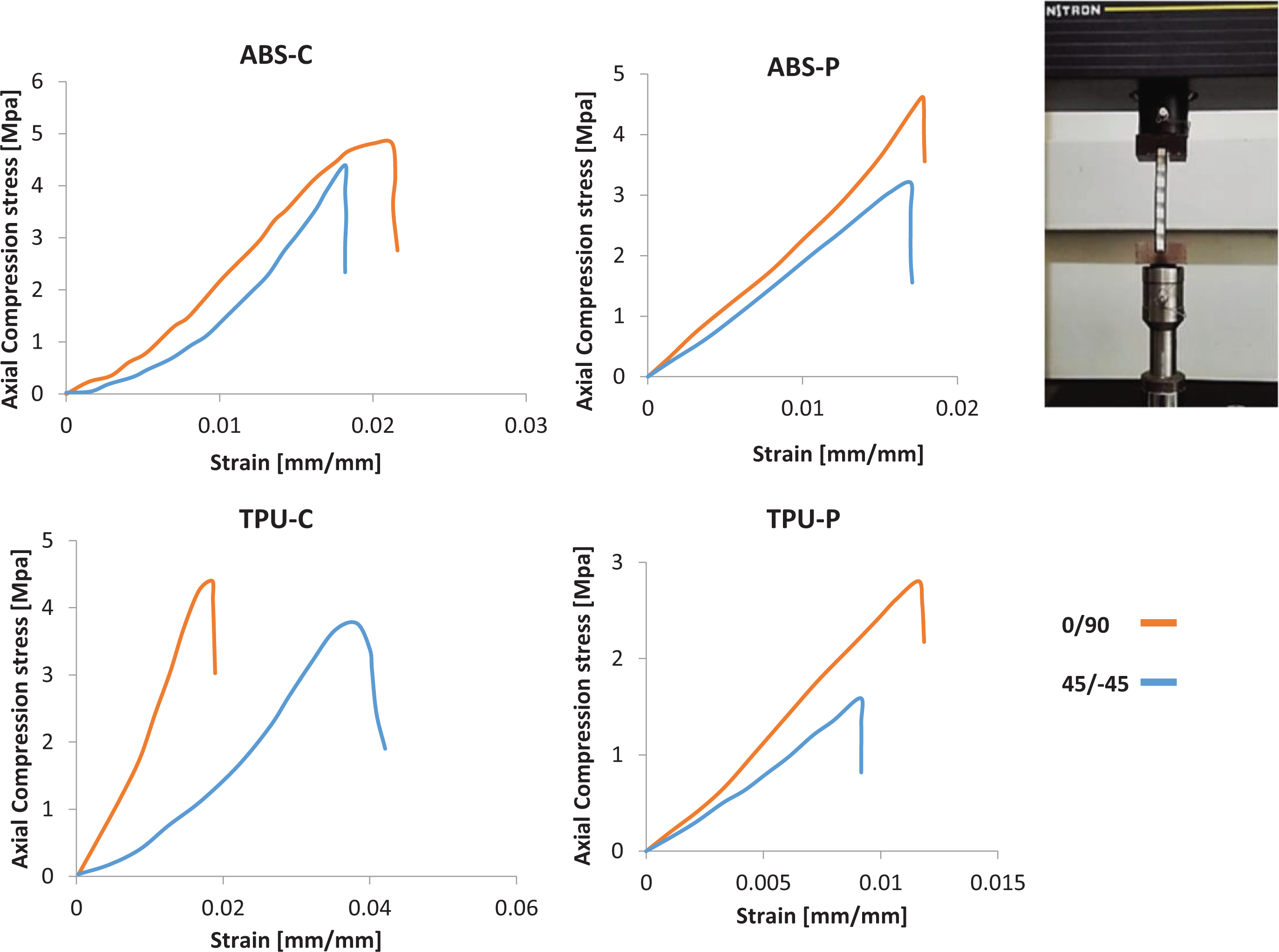
It is evident from Figure 11 that for all type of material combinations and raster angles, the stress increases likewise the strain increases. It was noticed that for most of the cases, the stress did not fall gradually after the maximum stress was reached, which indicates the brittle nature of specimens under compressive loading. Hence, strong monitoring of structures is required to avoid the major accident. The failure mechanism of edgewise/axial compression test is shown in the Figure 12. It was observed that after reaching a certain value of stress, the face sheets started to delaminate from the core, followed by wrinkling of face sheets and bending of the core.
Stress–strain behavior of printed structures under bending axial compression loads.
Modes of failure during axial compression loads.
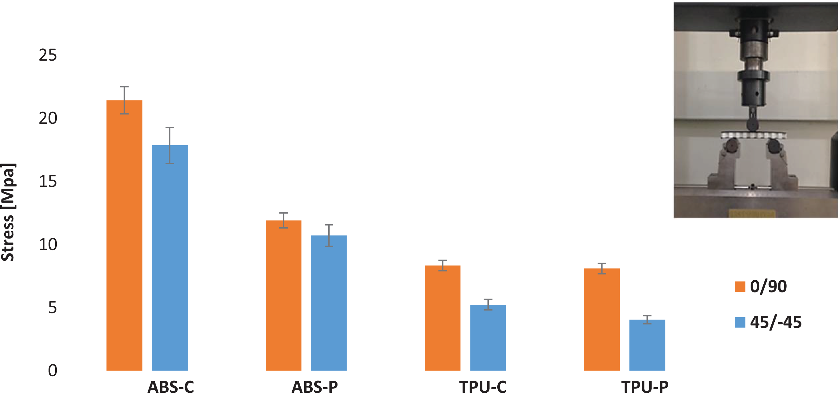
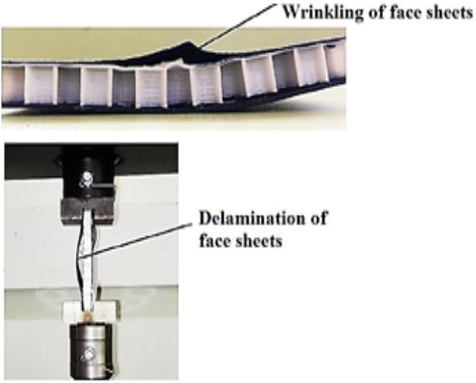
Figure 13 shows the combined effect of material and raster angle on the compressive properties of structure. As observable, there was a variability of compressive strength for different specimens, which reveals that material type has a strong influence on axial compressive properties of FDM-built HCSS. Comparing the peak stresses in Figure 13, it can be seen that ABS-C sandwich structures endured maximum axial compressive stresses. Whereas, TPU-P sandwich structures sustained the minimum stresses. This trend was same as seen before in the case of flexural testing. Thus, the possible reason could be same i.e. Interfacial bond strength between the core and face-sheets which will be explained in section 3.3.
Comparison of maximum axial compression stress endured by FDM-built HCSS.
Furthermore, the specimens fabricated with 45°/−45° raster angle exhibited lower stresses than 0°/90° raster angle specimens. This can be attributed to the fact that the specimens are stronger and stiffer in the filament direction. 24 It can be analyzed easily that if the specimens are printed at 0°/90° raster angle then, in axial compression, forces applied will be along the filament direction but in 45°/−45° the forces will be at some angle to the filament direction which results in the early failure of specimens.
Interfacial bond strength and its relationship with bending and compressive properties of structures
As discussed previously in section 3.1 and 3.2, the core and face sheet interfacial bond strength could have an influence on the mechanical properties of HCSS. Results of the bond strength testing for FDM-built HCSS are shown in the Figure 14 for the various materials under consideration. Figure 14(a) shows that ABS-C specimens withstood the normal stress than ABS-P specimens and TPU-C specimens endured the higher normal stress than TPU-P specimens. This implies that composite material face sheets are more compatible with the core of ABS and TPU than PLA material face sheets. This is because of the reason that C-PLA face sheets have rougher surface than PLA material face sheets hence they provide very good mechanical interlocking to bond with ABS and TPU core. Considering the effect of raster angle on the interfacial bond strength, it is noticeable from Figure 14(b) that the specimens printed with raster angle of 45°/−45° and 0°/90° happened to give almost the same interfacial bond strength.
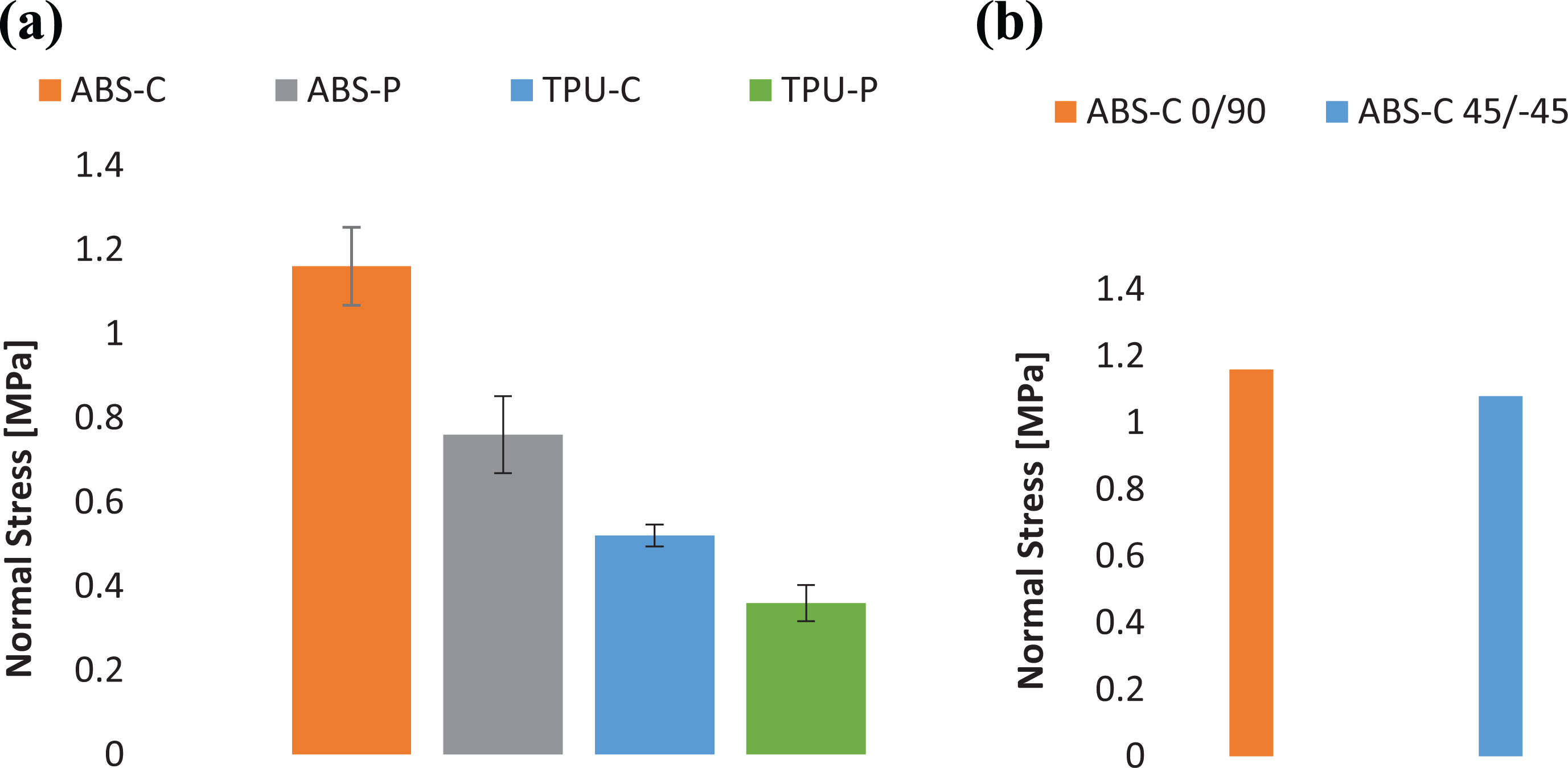
(a) Effect of variation in the material on interfacial bond strength. (b) Effect of variation in the raster angle on interfacial bond strength.
The failure mechanism of bond strength test is shown in Figure 15. From the pictures of the delaminated face sheets it can be seen that some of the patches of core material are left on the face sheets after delamination. However, the amount of patches is so small that the overall dominant failure is found to be the core to face sheet delamination. Other possible failure modes reported in the literature are crushing of core, crushing of face sheet before the bond failure but these are not acceptable according to the related standard C364-99. In all of the presently conducted bond strength tests, none of these failure modes (i.e. crushing of core, crushing of face sheet) were witnessed so the test results are valid.
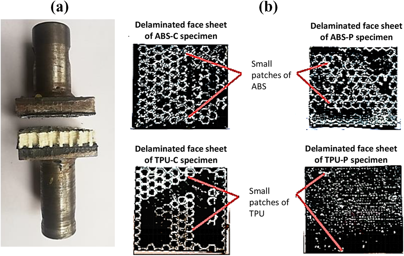
(a) Failure mode in bond strength test. (b) Delaminated face sheets of all the four types of specimens.
The comparison of interfacial bond strength with flexural and edgewise compressive strength is shown in Figure 16. It can be noticed that the specimens having highest interfacial bond strength also exhibit highest flexural and edgewise compressive properties and vice versa. So, it was found that the best mechanical performance of ABS-C specimens and worst performance of TPU-P specimens was due to their interfacial bond strength. Further, it can be stated that the bond strength between the face sheet and core have a major influence on the load-carrying capacity of FDM-built HCSS which is in accordance with the finding of Brischettoet al. 12
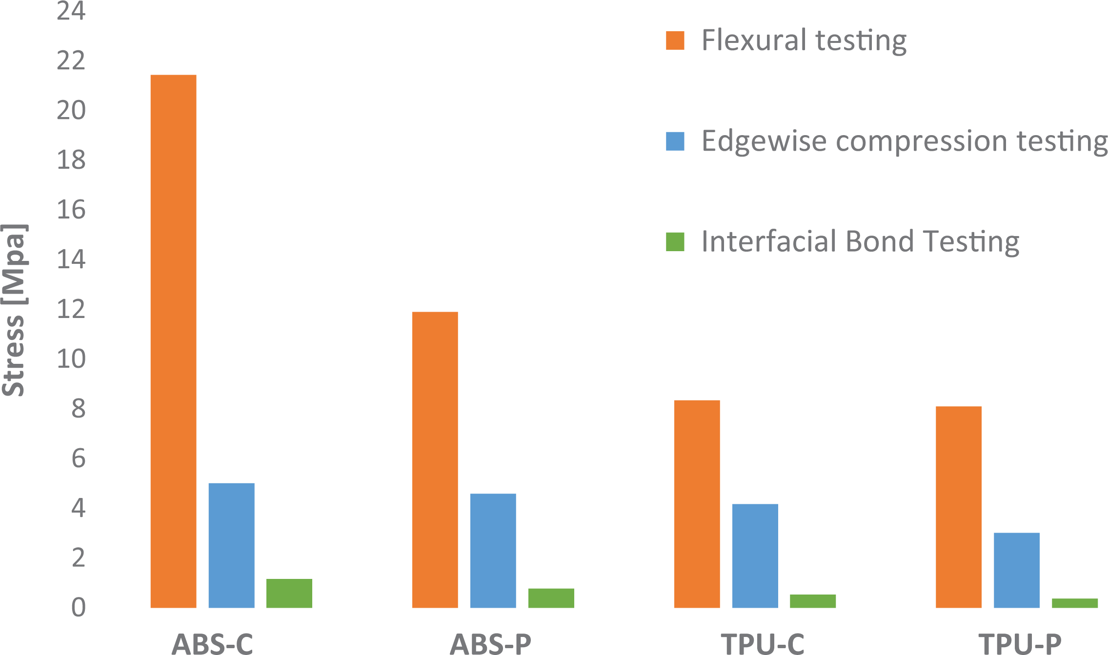
Comparison of maximum stress in flexural, edgewise compression, and interfacial bond strength tests of all the four types of specimens.
Conclusions
In the present study, the mechanical performance of honeycomb sandwich structures fabricated through FDM was investigated. A number of samples were produced by varying the material and raster angle and were subjected to different type of mechanical tests. The results demonstrated that the material and raster angle have combined (or interactive) effect on the load carrying capacity of the HCSS. Hence, the mechanical properties of FDM-built HCSS could be controlled by selecting suitable fabrication conditions (i.e. material type and raster angle). In flexural and edgewise compressive testing, ABS-C with raster layup of 0°/90° endured the maximum stresses before failure and TPU-C with raster layup of 45°/−45° withstood the minimum stresses.
However, in the interfacial bond strength testing, raster layup was found to have no significant effect on load bearing capacity. Therefore, the prime factor in deciding the superlative mechanical performance under this type of test is only material combination. Results of the bond strength testing for the various materials under consideration revealed that ABS-C specimens withstood the greater normal stress than ABS-P specimens and TPU-C specimens endured the higher normal stress than TPU-P specimens. This indicates that composite material face sheets are more compatible with the core of ABS and TPU than PLA material face sheets.
The failure in three types of tests namely flexure, compressive and bond strength tests commenced due to face/core delamination. This means that the dominant failure mode in FDM-built HCSS is delamination. It was found that the bond strength between the face sheet and core have a major influence on the load carrying capacity of FDM-built HCSS. In summary, it is recommended that ABS core with composite material face sheets and 0°/90° raster layups may be utilized to produce FDM-built HCSS with high mechanical performance.