
Abstract
This study presents an experimental investigation on thermoplastic carbon fiber composite based on PMMA resin interleaved with Polyamide electrospun nanofiber veils. In particular, the effect of improving the interfacial adhesion of the resin to nanofiber and carbon fiber on the fracture behavior of the laminates and the corresponding fracture mechanism was studied by using different molar concentrations of functional monomer hydroxyethyl acrylamide (HEAA) for copolymerization with methyl methacrylate. The effectiveness of the nanoreinforce has been addressed by Mode-Ⅰ and Mode-Ⅱ tests. The results showed that the fracture toughness of Mode-Ⅰ decreased firstly and then increased with an increase in HEAA feed with 0–5 mol% due to the change of crack tip path accompanied by the bridging mechanism shifting, the best performance was founded in 5 mol% HEAA-copolymerized thermoplastic carbon fiber composites (CFRTP) samples (17.6% for initiation and 28% for propagation); whereas a characteristic of increasing firstly and then decreasing performed under Mode-Ⅱ loading due to the formation of multilayer microcrack in nano-toughing matrix layer, the 3 mol% HEAA-copolymerized CFRTP samples exhibited good improvement (137% for initiation and 147% for propagation).
Keywords
Introduction
In facing the issue of increasingly profound climate change, governments around the world have also launched stricter carbon emission regulations. Existing data show that 100 kg weight saving in each automotive leads to a reduction in CO2 emission of 20 g/m. Using carbon fiber reinforced plastics to make automotive parts is the primary method to achieve automobile light-weighting. 1 Although thermosetting carbon fiber composites (CFRPs) based on High pressure resin transfer molding (HP-RTM) molding technology have been widely used in some luxury cars, the technical defects of low-production efficiency and non-recyclability limit the application of CFRPs in medium-end and low-end models. Thus, thermoplastic carbon fiber composites (CFRTPs) provide alternative options to remedy some defects of CFRPs.2,3 Generally, laminate composite materials are prone to inter-ply delamination due to their layup structure.4,5 In the last 20 years, the electrospun nanofiber veils had been proven the ideal reinforcement to be interleaved between two piles of CFRPs because of the following main aspects: thinness and light which make their impact on weight and thickness of the final manufactured negligible; porosity which makes resin flow easily through them without causing non-uniform dispersion of nanofiller; tiny volume which means the actual volume of the nanofiber interleaves shrinks when pressure is applied during the curing process; super well mechanical property due to nanofibers’ mechanical properties is significantly higher than those of the same material in bulk state.6,7 From the research of various aspects of electrospun nanofiber reinforced thermoplastic resin, electrospun nanofiber can potentially enhance the damage resistance of CFRTPs laminate system,8–11 and the mechanical toughening effect of nanoreinforce in CFRTPs laminate system is an issue to be characterized.
There are many excellent reviews in the literature dealing with the influencing factors on the enhancement performance of thermoplastic nanofiber veils, center on the polymer type of nanofiber,12,13 the areal density of nanofiber,12,14,15 the thickness of a nanofibrous interlayer,16,17 and physical properties of nanofibers. 18 Although the influences of these factors are essential, it is noteworthy that the nanofiber fracture mechanism consistently exhibits pull-out mode without causing apparent damage to the nanofibers and the interface separation between nanofiber and resin from most observations of the fracture surface.14,18–21 These observations suffice to illustrate that the compatibility between most thermoplastic veils and resin is typically poor. Moreover, due to the traditional active methods such as corona discharge, plasma treatment, acid etches, and oxidizing flame treatment could create severe damage to the nanofiber. There is no denying that one of the significant challenges for adhesion improvement is surface treatment methods for thermoplastic nanofiber veils. Recently, Dong et al. 19 proposed to employ a UV-irradiation technique to activate the surface of the nanofiber veils to improve their adhesion with epoxies. It was found that the application of the UV-irradiation to Polyphenylene sulfide (PPS) veils significantly improved the toughness performance of the laminate manufactured by resin transfer molding of non-crimp fabrics by introducing significant carbon delamination and PPS fiber damage during the fracture process. On the other hand, the semi-cured epoxy resin in the Unidirectional (UD) prepreg has a small number of reactive groups to covalently bond to the functional groups of UV-treated PPS surface, which could negatively affect the compatibility between the nanofibers and epoxy, leading to the deterioration of the fracture behavior of UD prepregs laminates. This suggests that the thermoplastic nanofiber surface treatment has great differences in the interlayer toughing of laminates with different resin systems.
Thus, the utilizing of functional monomer hydroxyethyl acrylamide (HEAA) for copolymerization with methyl methacrylate (MMA) as the modified thermoplastic resin was proposed to improve nanofiber/resin interfacial adhesion while optimizing carbon fiber (CF)/resin interfacial adhesion based on the knowledge of previous research. 22 Subsequently, the double-cantilever beam (DCB) experiments and end notched flexure (ENF) experiments were employed to investigate the effect of modified resin copolymerized with different molar concentrations of HEAA on the interlayer toughing effect of Polyamide (PA) nanofiber veils. In addition, the scanning electron microscope (SEM) photos taken from the fracture surface were available for analyzing the fracture mechanism. The results were compared with those of pure polymethyl methacrylate (PMMA) CFRTP to fully understand the effect of interfacial adhesion improvement of CF/matrix and nanofiber/matrix on the nanofiber interlayer toughness enhancement.
Experimental
Prepreg sheet preparation
Properties of copolymer.
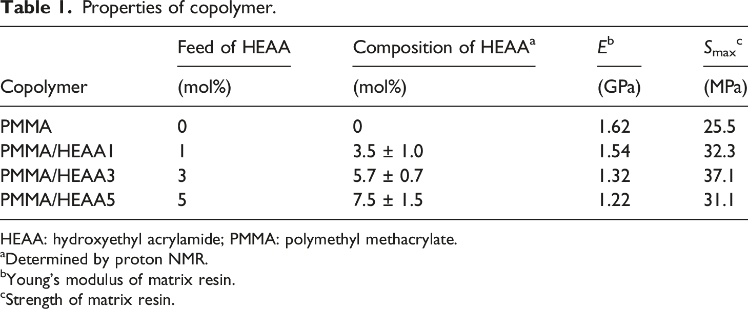
HEAA: hydroxyethyl acrylamide; PMMA: polymethyl methacrylate.
aDetermined by proton NMR.
bYoung’s modulus of matrix resin.
cStrength of matrix resin.
In addition, the tensile tests were performed to examine the mechanical properties of copolymers as the matrix with the form of a 40 mm × 10 mm × 0.3–0.5 mm (length × width × thickness) rectangular strip shape, gage length is 20 mm. The samples were extended at 0.2 mm/min, and the typical stress-strain curve was extracted from the load-displacement data obtained from the tool. Young’s modulus was obtained from the initial slope of the stress-strain curve. The tensile test results were summarized in Table 1. Figure 1 shows that the nonlinear fracture behavior of copolymers gradually changed from brittle fracture to yield plastic fracture, and the linear behavior also gradually exhibited softening characteristics with the increase of the HEAA component. Typical tensile stress-strain curves for copolymers use as matrix for carbon fiber reinforced plastics composite.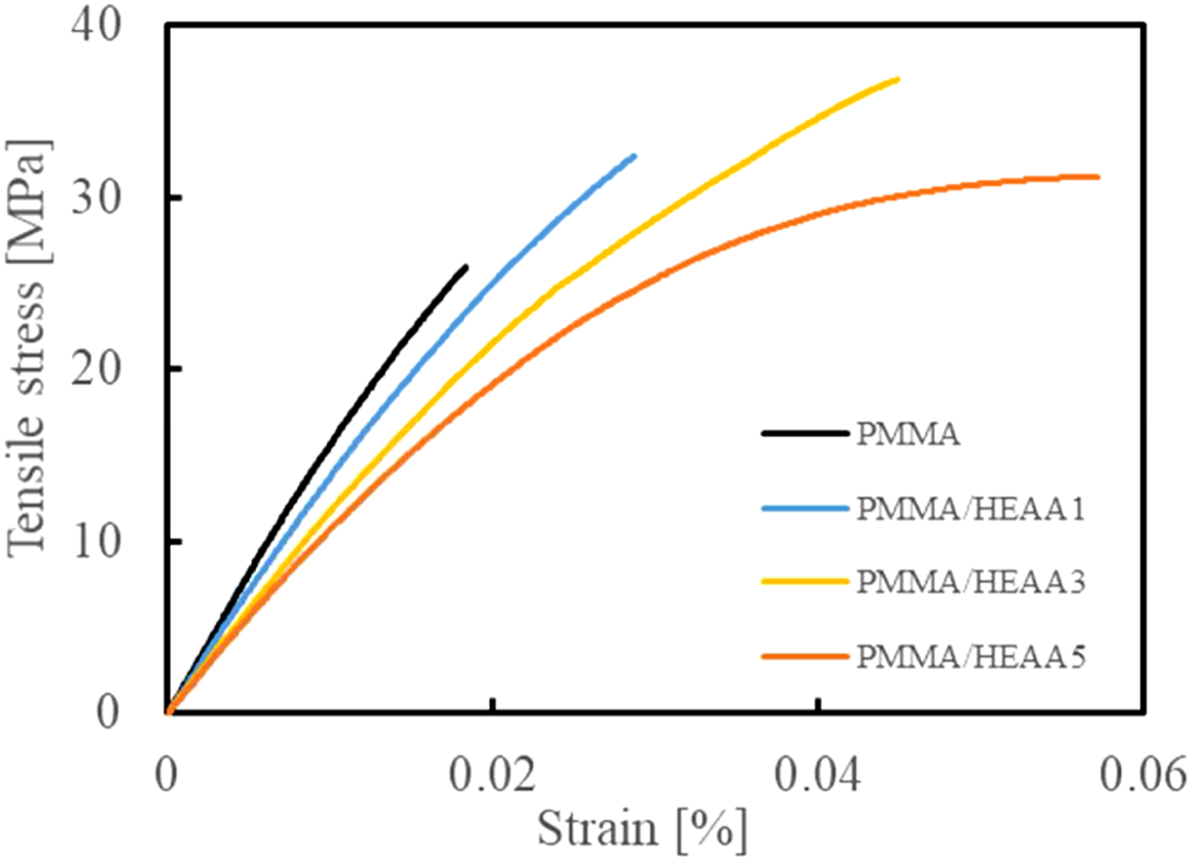
Fabrication of thermoplastic carbon fiber composites laminate
The nanofiber reinforced composite panels and virgin with four piles of prepreg sheet in a 0° orientation were prepared following the method described in the JIS K 7086 standard.
23
A stainless film (0.015 mm thick) was inserted in the middle-plane at the tip of the panel to form a 40 mm initial artificial crack. Besides, the nanofiber veils were needed to be placed at the end of the release film at the same time to form a nano-modified interlayer for the nanofiber reinforced composite. The prepreg layup was transferred into a thermo-compressor at 185°C and 0.4 MPa to melt the matrix. After 20 min, the pressure was then increased to 4 MPa and kept for 20 min. Afterward, the pressure was removed, and the mold cooled down to ambient temperature. Figure 2 shows that the cross-sectional micrograph of specimens with nanofiber and without nanofiber, it can be found that the influence of nanofiber veils as the nanoreinforce inserted into the interlayer on the thickness of the final manufactured can be negligible due to their ultra thin-film characteristics (sample with nanofiber: 3.3 mm, sample without nanofiber: 3.2 mm). And the Vf of nanomodifed sample and controls is 50.3% and 51.5%, respectively. Here, Electrospun nanofiber veils, called Xantu.Layr XLB, were supplied by Revolution Fibres Ltd, which had an areal density of 4 g/m2. The composition of nanofibers is PA-XD10 produced by Mitsubishi Gas Chemical Inc. Photograph of double-cantilever beam and end notched flexure sample (a) and micrograph of specimens with nanofiber (c) without nanofiber (b) in cross-section.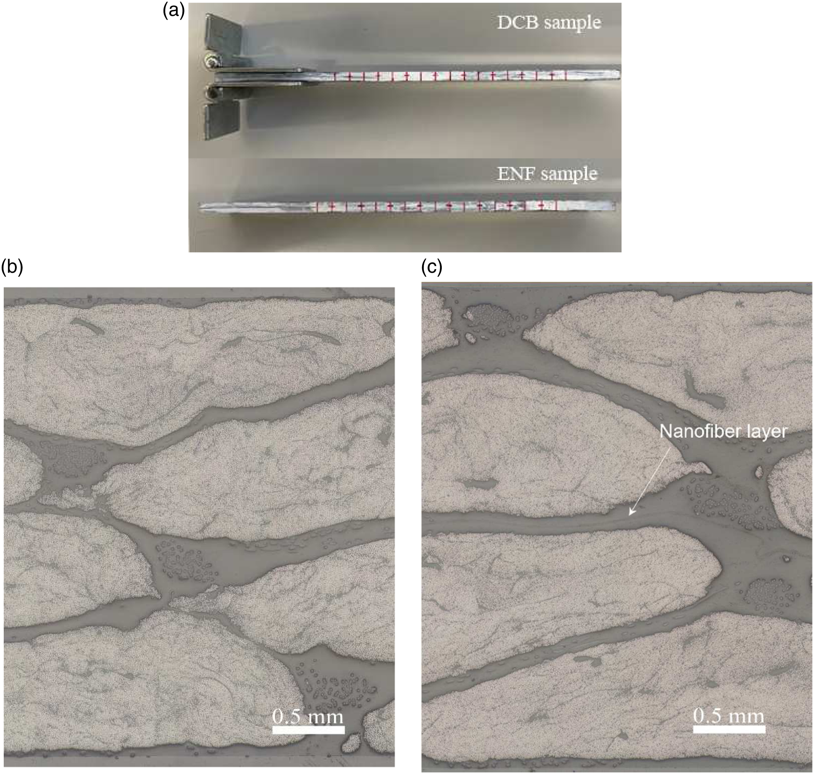
Fracture mechanics tests
The DCB test was performed to investigate the delamination of material in an opening mode of failure (Mode-Ⅰ) according to standard JIS K 7086 for carbon fiber reinforced plastics
23
using a universal test machine equipped with a 50 kN load cell in 1% load range. The geometry of the specimens was L = 140 mm in length and b = 20 mm in width. Piano hinges were bonded to the outer surface of the specimens to apply the opening forces. The tests were carried out at a constant crosshead speed of 0.5 mm/min. During the test, the load-displacement data was recorded by computer, and a traveling microscope which equipped with displacement recorder was employed to measure the progressive crack length by focusing on the edge of the DCB specimen. The fracture energy release rate of DCB tests was calculated using a modified beam theory (MBT), as follow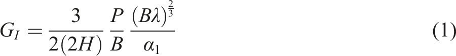
The ENF tests were performed to investigate the delamination of material in an in-plane shear mode of failure (Mode-Ⅱ). And the tests were conducted on a universal test machine fitted with a 5 kN load cell in 100% load range at a constant displacement rate of 0.5 mm/min, as recommended in standard JIS K 7086.
23
The geometry of the ENF specimen was same as DCB tests, and the span width was 100 mm. The levels of critical energy release rate (G
ⅡC
), which determined by the 5% offset approach, and propagation energy release rate (G
ⅡR
), which determined at the maximum flexural load, have been calculated, as given by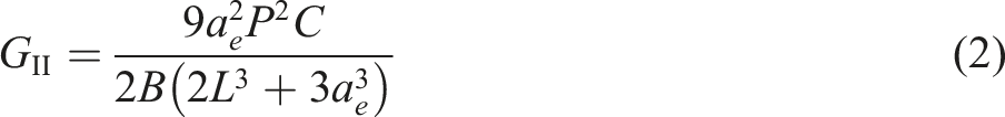
Nomenclature of thermoplastic carbon fiber composites specimens used for mechanical tests.
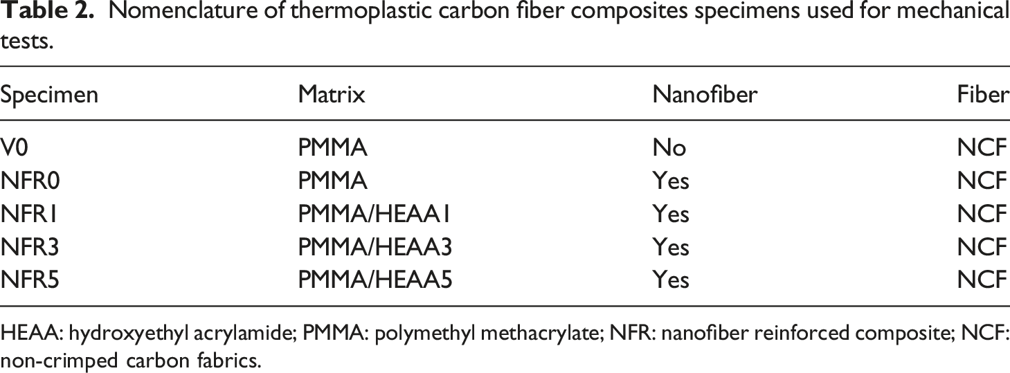
HEAA: hydroxyethyl acrylamide; PMMA: polymethyl methacrylate; NFR: nanofiber reinforced composite; NCF: non-crimped carbon fabrics.
Fracture surface observation
Hitachi S-4700 field emission SEM was employed to inspect and image the fractured surface of the sample. The samples were plasma-coated with osmium for 10 s.
Result and discussion
Mode-Ⅰ fracture toughness behavior
The DCB tests were carried out on each configuration, and the typical load-displacement curves are shown in Figure 3. All configurations performed linear elastic behavior for the initial loading phase, then the curves exhibited nonlinear behavior with a jagged shape until the end of load, linked to unstable crack propagation through the specimen. Even the maximum load value of NFR1 and NFR3 had a negligible difference with V0 configuration and the considerable high values of maximum load were found in the curves of NFR0 and NFR5. Those preliminary findings supposed that the nanofiber modified interlayer had a positive effect on delaying crack initiation, leading to an increase in the maximum load in laminate. Typical Mode-Ⅰ load-displacement curves for thermoplastic carbon fiber composites specimens.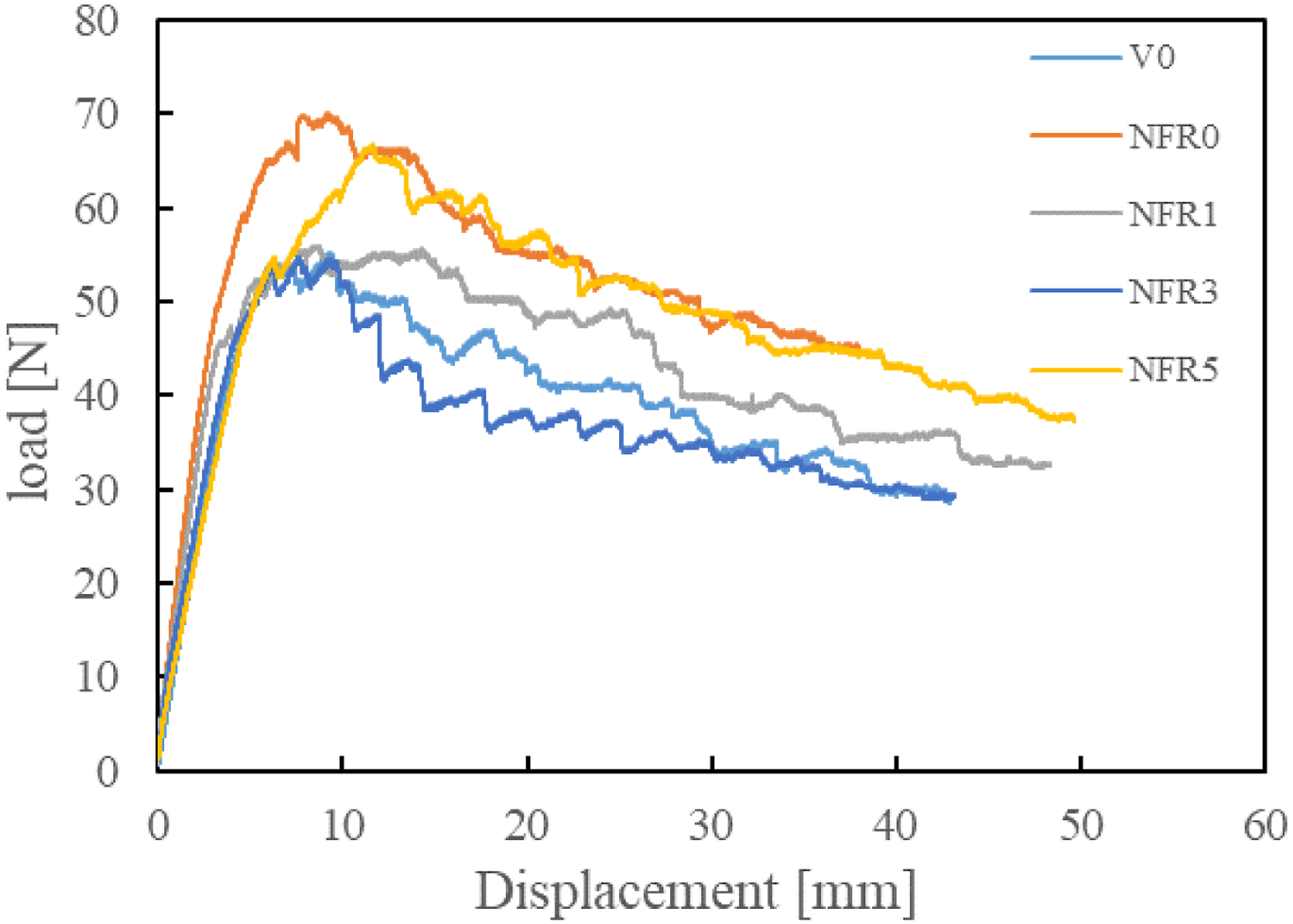
According to the MBT method, the G
I
has been calculated from the load-displacement data and the incremental crack length. The typical Mode-I R curves plot can be seen in Figure 4, and the corresponding GIC and GIR are summarized in Table 3. The overall trend for NFR configurations was almost the same as for virgin configuration in the sense that G
I
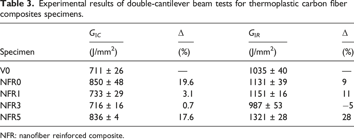
increase with the crack length growth (Figure 4). The GIC and GIR of NFR0 configuration were 19.6% and 9% higher than those of the V0 configuration, respectively, as shown in Table 3, indicating that the PA nanofiber interleaving positively affects Mode-I fracture toughness for CFRTPs laminate system. Nevertheless, the modified resin of copolymerization with HEAA exhibited a “decreasing firstly and then increasing” trend on the interlayer toughing effect of PA veils. As the molar concentration of copolymerization with HEAA increased to 3 mol%, the GⅠC and GIR of nanofiber interleaved composite dropped from 19.6%, 9% to 0.7%, −5% compared to V0, respectively. The molar concentration of copolymerization with HEAA increased to 5%, both values of GⅠC and GIR improved again into 17.6%, 28% in relation to V0, respectively, see Table 3. Thus, it is revealed that the fracture mechanism for the nanofiber interleaved layer is varied with the modification of matrix resin. Typical Mode-Ⅰ R curves for thermoplastic carbon fiber composites specimens. Experimental results of double-cantilever beam tests for thermoplastic carbon fiber composites specimens. NFR: nanofiber reinforced composite.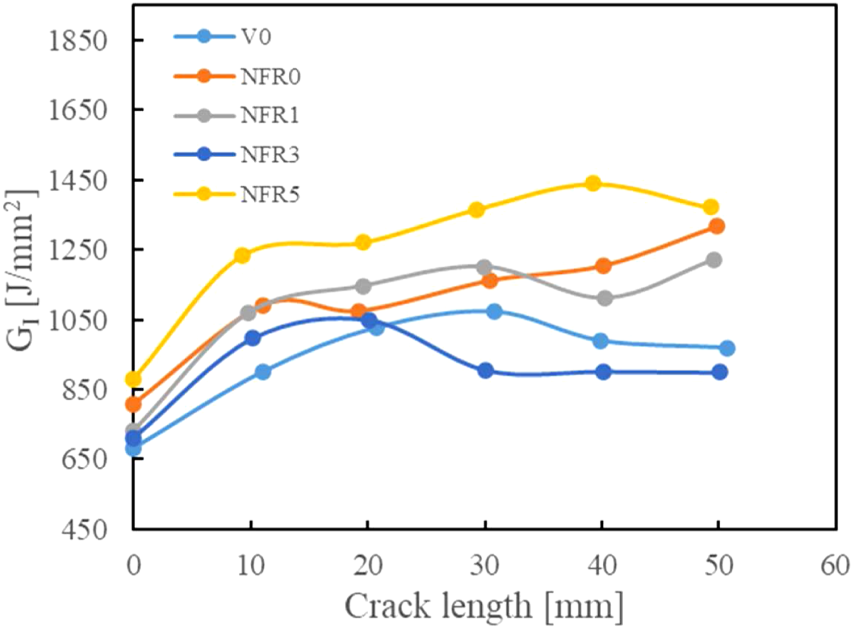
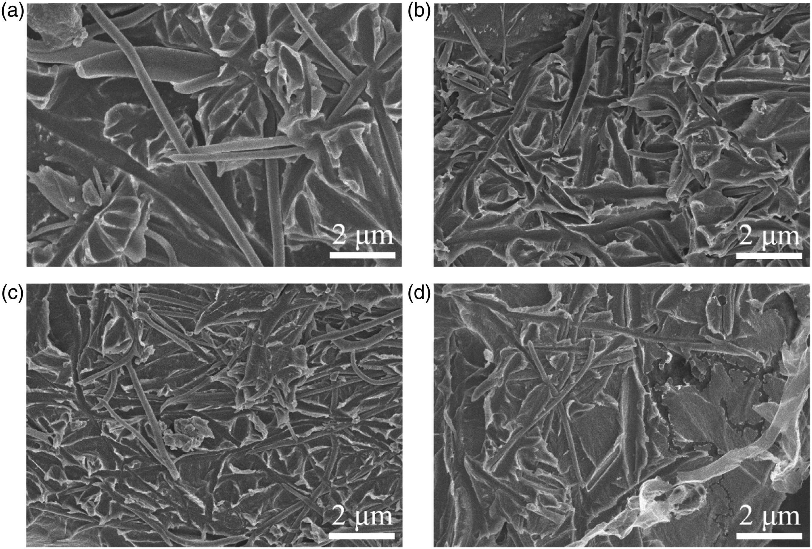
To further explore the fracture mechanism of DCB specimens, the SEM images of a fracture surface and schematic views of the crack path for each configuration are showed in Figure 5. Some industrial research institutes report that the surface of commercially available CFs is typically designed for interaction with epoxy polymers and not for acrylic polymers such as PMMA.24,25 Thus, the fracture surfaces of V0 samples appeared to be rough. Brittle fractures of resin debris and breakages of CF fibers could be observed, indicating that the opening load caused the tensile fracture on the interlayer resin in the thickness direction, and the CFs were also pulled out from the matrix leading to the fiber bridging when the fractured resin debris peeled off the fiber layer (Figure 5(a)). For NFR0 samples, the uneven fracture surface of CFs covered with the local nanofiber rich zone, and pull-out CFs can be noted (Figure 5(b)). A nanoscale microphotograph exhibited that the local nanofiber zones contain the plastically deformed PMMA and pull-out nanofibers, as shown in (Figure 10(a)). It is suggested that a crack alternatingly propagates above and below the nanofiber toughened interlayer when a nanofiber veil interleaved. The presence of additional nanofiber bridging led to the higher fracture toughness of the NFR0 samples compared to the V0. However, as the molar concentration of copolymerization with HEAA increased to 3mol%, the nanofiber rich zones almost occupied the fracture surface, which was eventually with fewer pull-out CFs and fractured matrix (Figure 5(c) and (d)), revealed that cracks propagate directly through the nanofiber toughed layer. This phenomenon indicated a conversion of bridging mechanism from the Hybrid bridging of CF and nanofiber to the single bridging of nanofibers, resulting in Mode-I fracture toughness decreased. For the NFR5 specimen, the Hybrid bridging of CF and nanofiber relating to the appearance of an uneven fracture surface with local nanofiber covering reappeared, see in Figure 5(e). Moreover, the surface of deboned CFs covered with the resin matrix, indicating the resins deformed before fracture. Consequently, the Mode-I fracture toughness increased again. Based on our finding above, it can be concluded that the change of crack tip path accompanied by the shifting of the bridging mechanism determines the level of Mode-I fracture toughness. Typical scanning electron microscope images of Mode-Ⅰ fracture surface and schematic views of delamination path for specimen (a) V0, (b) NFR0, (c) NFR1, (d) NFR3, and (e) NFR5. NFR: nanofiber reinforced composite.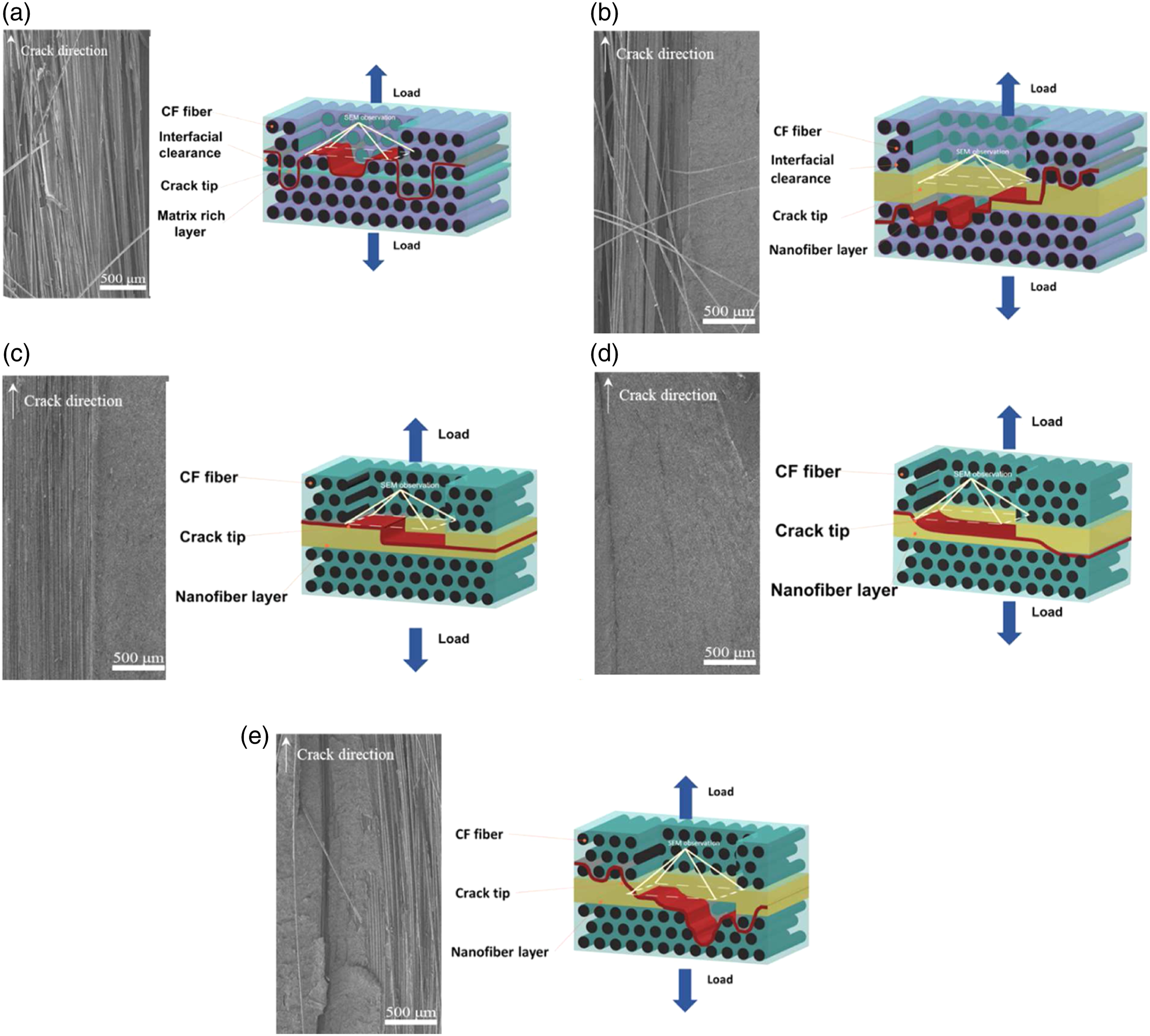
Mode-II fracture toughness behavior
In the case of Mode-II loading, the tests were realized by normal flexural experiment, and the typical load-displacement curves can be seen in Figure 6. A similar smooth non-linear behavior can be identified from the critical point of initial linear behavior to the maximum load of specimen failure, corresponding to crack propagation with a relatively stable stick-slip behavior. Typical Mode-Ⅱ load-displacement curves for thermoplastic carbon fiber composites specimens.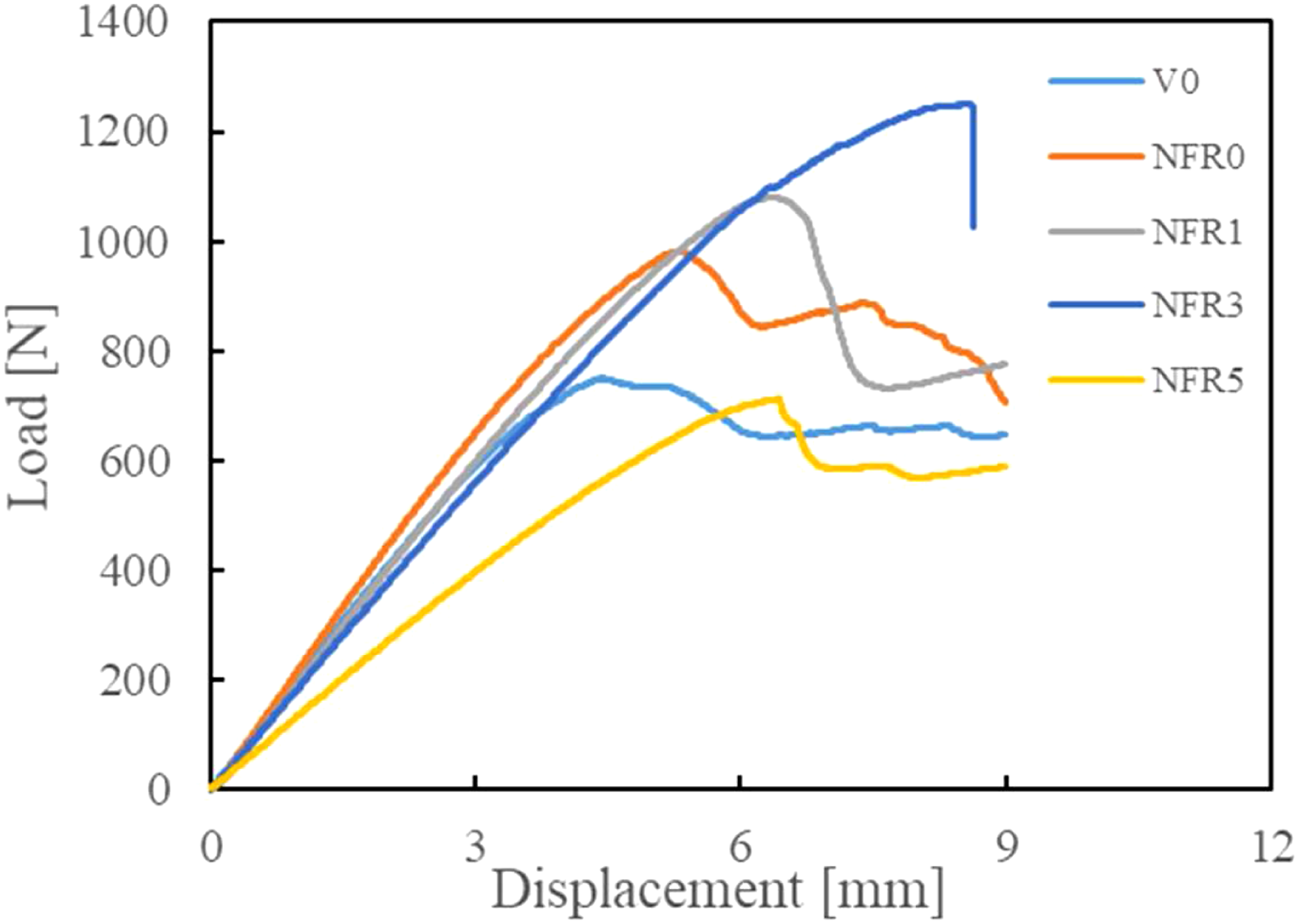
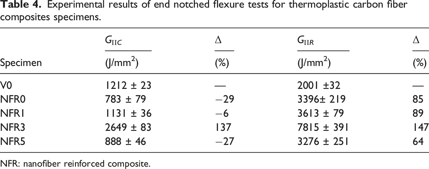
From the ENF tests, the G
II
has been calculated several times during the tests, the typical Mode-II R curve has been plotted in Figure 7, and the corresponding fracture energies are summarized in Table 4. All of the configurations exhibited a rising trend, see in Figure 7. It was found that for the NFR0 configuration, the nanofiber veil interleaving had a negative effect on the GII C about −29%, on the contrary, which brought with it a massive improvement in GII R about 85% as a consequence of the nanofiber bridge effect compared to V0, see in Table 4. Concerning the effectiveness of modified resin copolymerized with the different molar concentration of HEAA on the interlayer toughing effect of PA veils, the copolymerization with HEAA had a positive and significant relationship with GII C and GII R from −29%, 85% for NFR0 to 137%, 147% for NFR3 in relation to V0, respectively; however, the GII C and GII R of NFR5 return to a low value, see in Table 4, it was attributed to the elastic modulus of the NFR5 samples dropped sharply with the high molar concentration of copolymerization with HEAA which can be confirmed from the initial elastic region in Figure 6. It is revealed that modified resin has a positive effect on the interlayer toughing by PA veils under Mode-Ⅱ loading; However, it is inevitable that the interlaminar toughening effect of PA veils decreases with the weakening of resin properties due to the excessive content of HEAA (Table 1). Typical Mode-Ⅱ R curves for thermoplastic carbon fiber composites specimens. Experimental results of end notched flexure tests for thermoplastic carbon fiber composites specimens. NFR: nanofiber reinforced composite.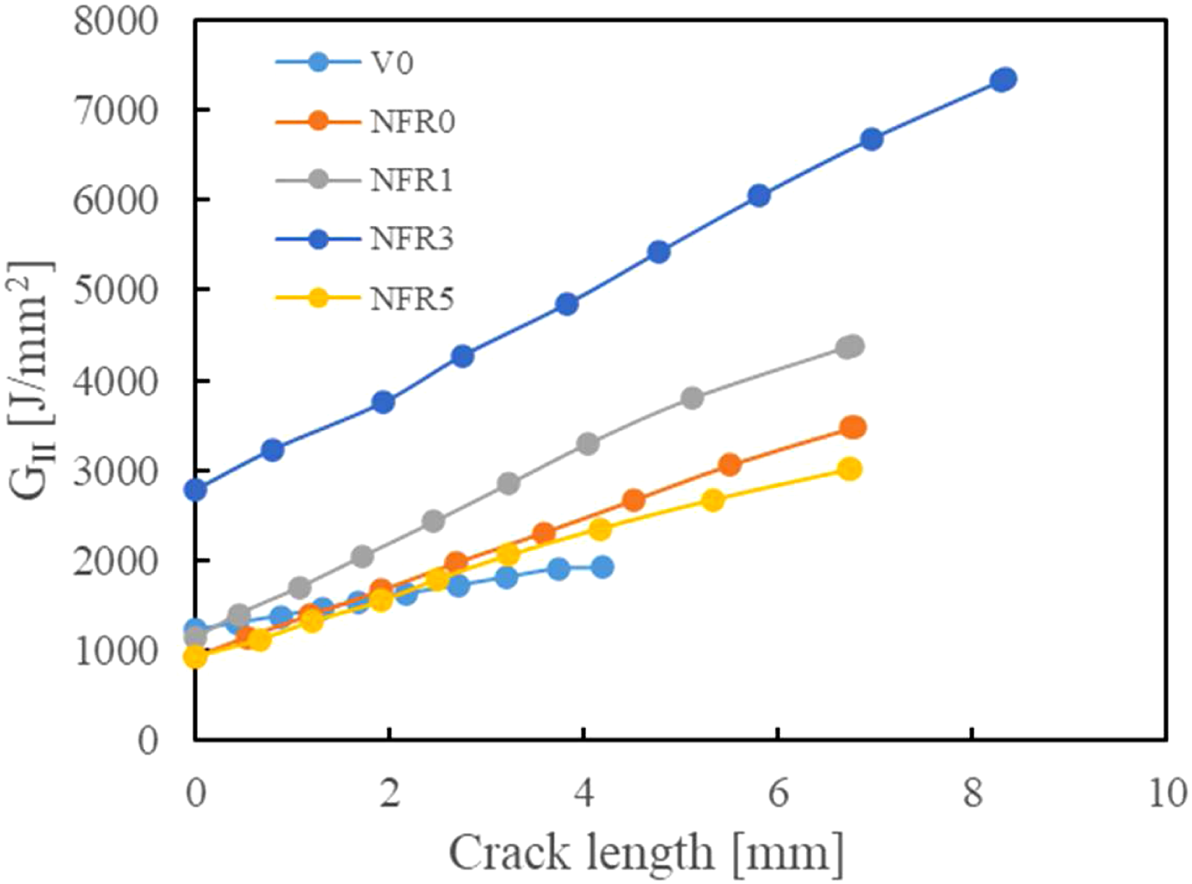
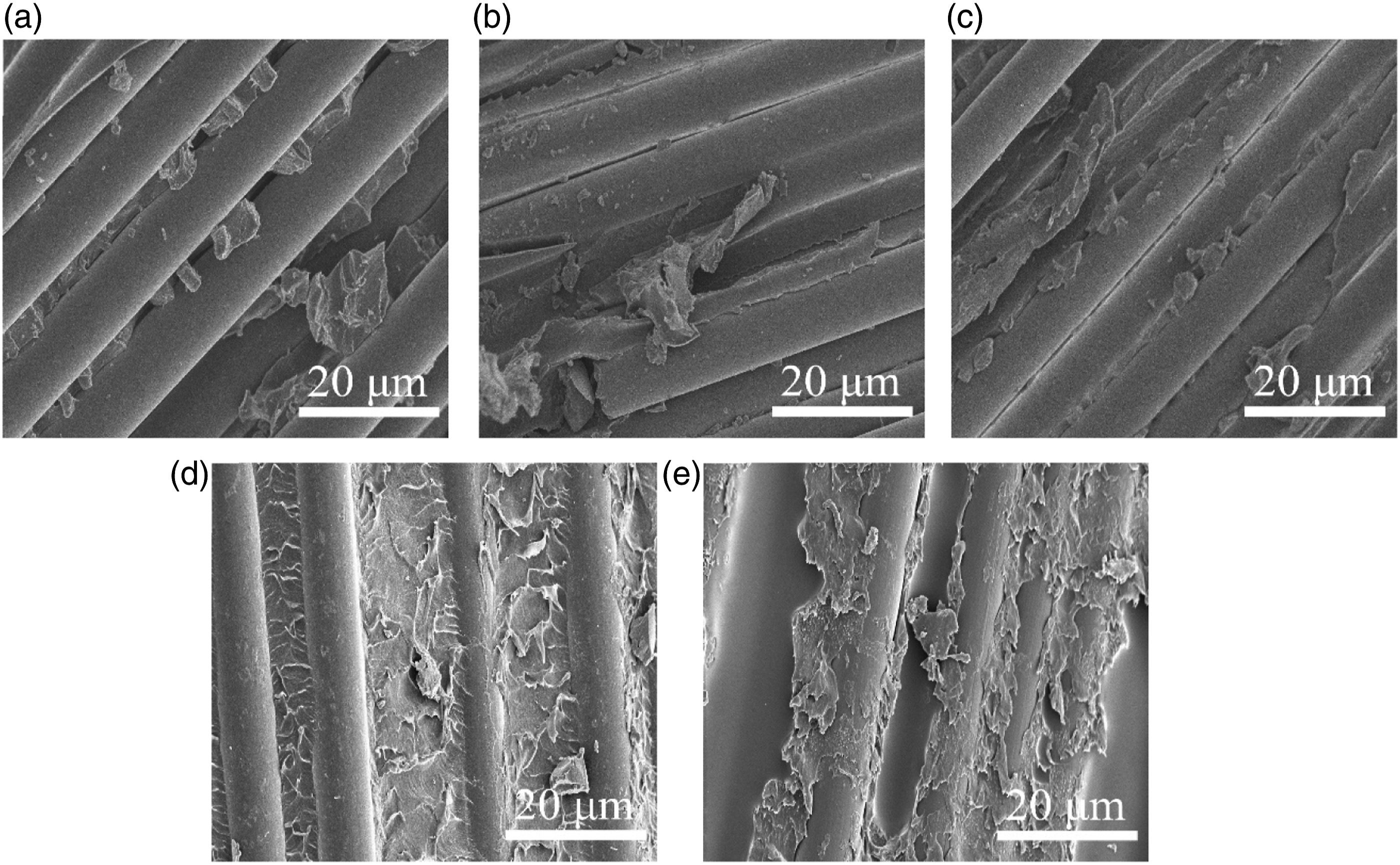
The fracture surfaces of ENF samples after Mode-Ⅱ loading are shown in Figure 8. Smooth and continuous CFs were found from the V0 interface (Figure 8(a)). The crack is mainly located at the interlayer matrix. A combination of hackle formation in the matrix and interfacial failure at CF/matrix suggested the failure mechanism of V0 samples, similar to previous works.26,27 With a nanofiber interleaved into the laminate, a distinguishable interlaminar region of the nanofiber toughed layer with a near right-angle edge is present in the NFR0 laminate (Figure 8(b)), which means the crack front passes from one side of interlayer to the other. The nanofiber bridging in the fractured region of the interlayer provides more resistance to the Mode-Ⅱ crack propagation(GⅡR) due to the higher ductility of the PA compared with the resin. But it must be pointed out that the right-angle edge of nanofiber toughed layer and regular CFs surface indicated the microcrack initiation alternated from a cohesive matrix failure to interfacial failure between nanofiber interlayer and CFs. That is the reason why the GⅡC decreased. Furthermore, the multilayer shape of deformed nanofiber toughened resin is visible for the fracture surface of NFR1 samples and NFR3 samples (Figure 8(c) and (d)), indicating a large amount of nanofiber bridging acted in the thickness direction of the toughened matrix layer. Because under Mode-II load, the two parts of the specimen slide only a few millimeters so that the nanofibers can bear longer load after crack propagation, and the enhancement is much higher than that of the DCB process at each instant.13,28 Therefore, the Mode-Ⅱ fracture energy increases greatly. But for the NFR5 samples, the partial crack deviation from toughened interlayer region to interface of CFs and the matrix elastic modulus weakening caused a reduction of fracture energy absorbing (Figure 8(e)). Therefore, taking the above observations into account, the appearance of a multilayer microcrack in the nanotoughed layer plays a vital role in the improvement of Mode-II toughness. Typical scanning electron microscope images of Mode-Ⅱ fracture surface and schematic views of delamination path for specimen (a) V0, (b) NFR0, (c) NFR1, (d) NFR3, and (e) NFR5. NFR: nanofiber reinforced composite.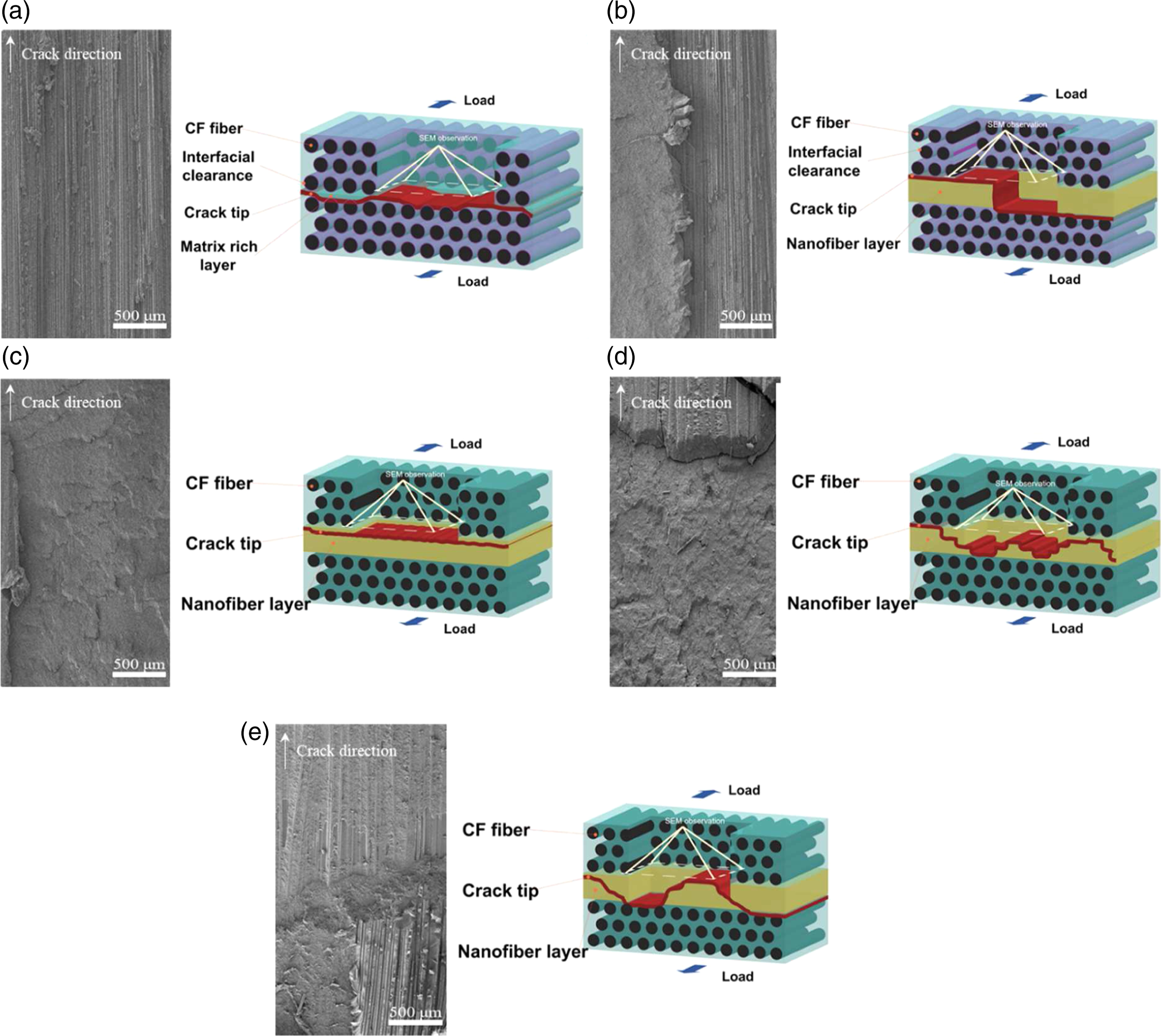
Interfacial adhesion and toughing mechanism
As the observations mentioned above, the variation of HEAA copolymerization has a crucial influence on the change of crack tip path under opening load and the multilayer microcrack formation in nanofiber toughed interlayer layer under shearing load. Thus, the fracture surface of the nanofiber toughened layer and the interface of the CFs were investigated, shown in Figures 9–12, to fully understand the influence of fiber/matrix adhesion, nanofiber/matrix adhesion, and property of modified matrix on the toughing mechanism. Typical scanning electron microscope images of Mode-Ⅰ fracture interphase of carbon fiber layer in specimen (a) V0, (b) NFR0, (c) NFR1, (d) NFR3, and (e) NFR5. NFR: nanofiber reinforced composite. Typical scanning electron microscope images of Mode-Ⅰ fracture surface of nanofiber-toughened layer in specimen (a) NFR0, (b) NFR1, (c) NFR3, (d) NFR5. NFR: nanofiber reinforced composite. Typical scanning electron microscope images of Mode-Ⅱ fracture interphase of carbon fiber layer in specimen (a) V0, (b) NFR0, (c) NFR1, (d) NFR3, and (e) NFR5. NFR: nanofiber reinforced composite. Typical scanning electron microscope image of Mode-Ⅱ fracture surface of nanofiber-toughened layer in specimen (a) NFR0, (b) NFR1, (c) NFR3, (d) NFR5. NFR: nanofiber reinforced composite.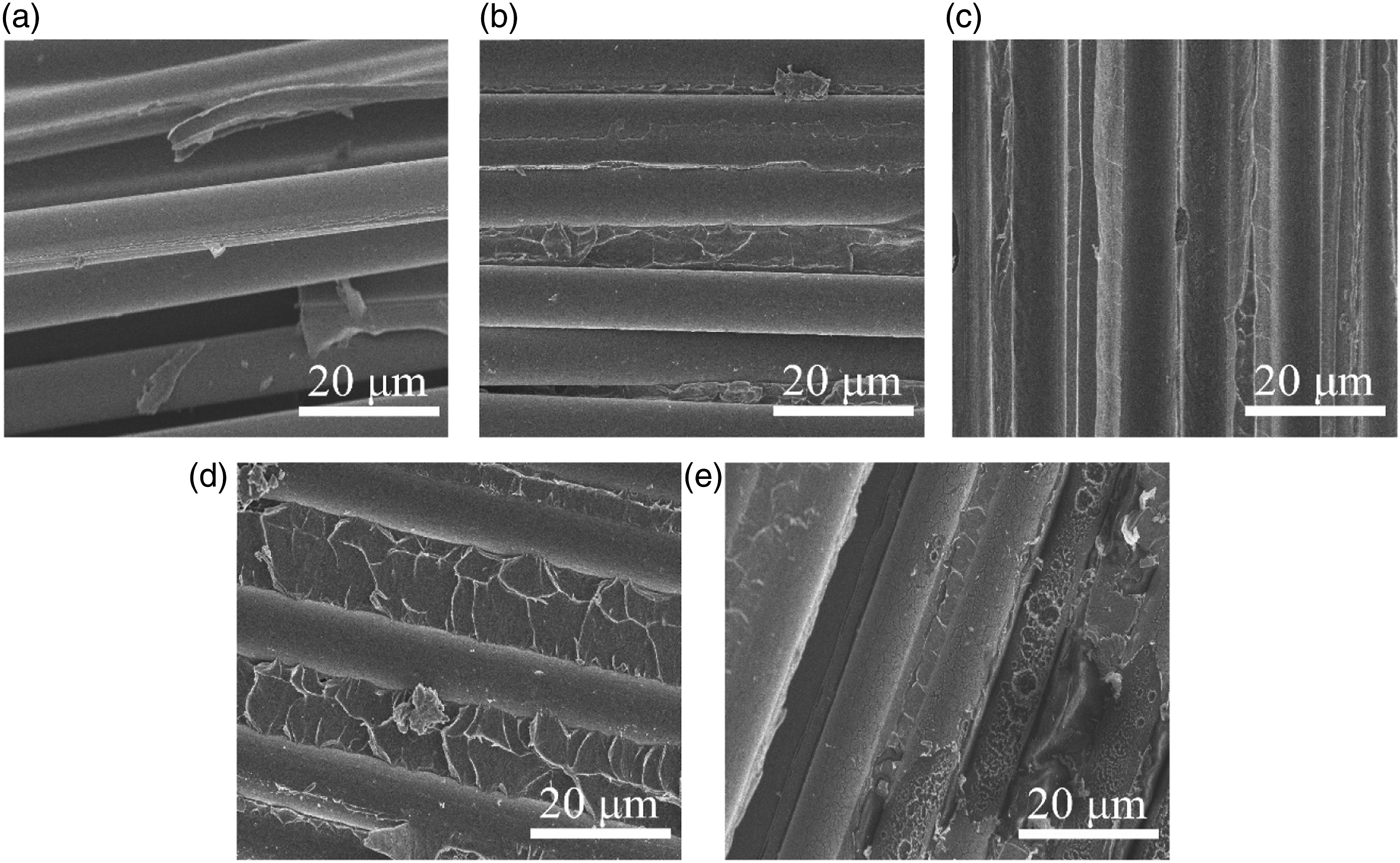
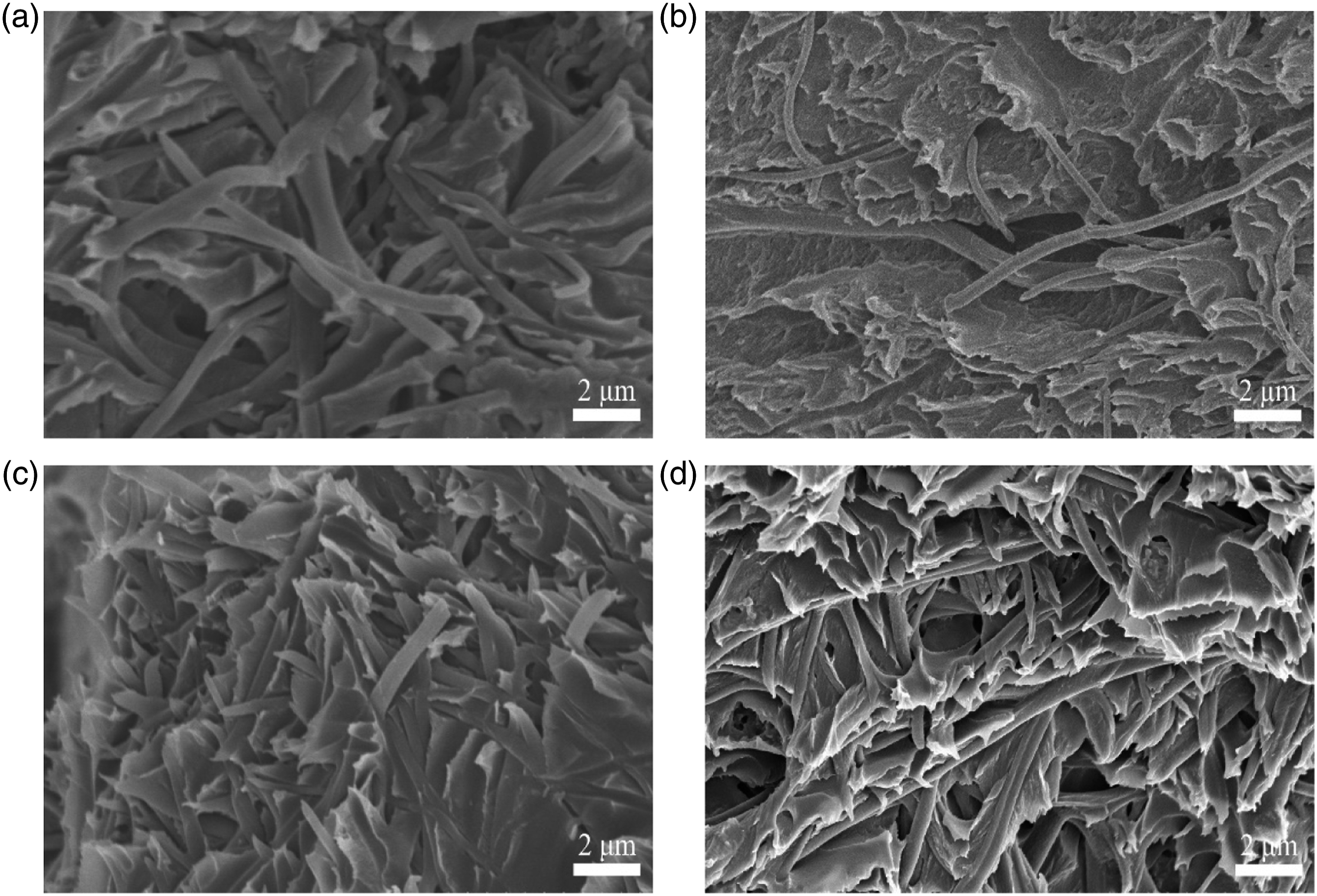
For DCB samples, the carbon fiber with smoothness surface was exposed on the fracture surface of the pure PMMA samples (Figure 9(a) and (b)). On the contrary, with the increase of HEAA content, the carbon fibers gradually deposited into the matrix (Figure 9(c) and (d)). It is suggested that a better adhesion of the resin to the fiber surface in case the resin-modified by copolymerization with HEAA is the reason for the crack propagating above the CF ply, as such, the fewer pull-out CFs is observed (Figure 5(c) and (d)), indicating the CFs bridging reduced. Hence, only marginal improvement of G ⅠC and negative effect of G IR compared to the virgin sample. Additionally, Figure 10(a) shows that pull-out nanofibers in long and continuous form remain in the fracture surface of the pure PMMA samples. Since the high displacement of the two interfaces of halves during the DCB experiment results in a higher elongation of the nanofiber, the pull-out of nanofibers ensures that more nanofibers are elongated and break in the sites were far from the crack tip, resulting in absorption of more energy. By contrast, fewer pull-out nanofibers on the fracture surface of HEAA copolymerized samples possessed sharp damaged tips, with the main section of nanofibers embedded in the matrix (Figure 10(b) and (c)). This phenomenon demonstrated that the improvement of nanofiber/matrix adhesion causes the nanofibers to be broken in a limited elongation range, thereby enabling the small amounts of nanofibers bridging to occur only at the tip of the crack, which agrees with Ref. 29. Thus, the fewer CFs bridging, together with a reduction in amount nanofiber bridging upon matrix modification, could negatively affect the Mode-Ⅰ fracture behavior of laminate. As for the NFR5 sample, although the completely embedding of broken nanofibers in the resin demonstrated less nanofiber bridging (Figure.10(d)). Still, a more fractured matrix is attached to deboned CF bundles (Figure 9(e)), indicating that the bonded CF bundles pull out from the CF layer to form a bridging effect due to the low strength and softening of the matrix (Table 1). This explained why G Ⅰ of NFR5 rises again compared to V0 samples.
For the ENF samples, Figure 11(c) and (d) show that CFs gradually buried with resin, and the plastic deformed resin debris remained on the fiber surface with the molar concentration of HEAA rising compared to pure PMMA samples (Figure 11(a) and (b)). These phenomena indicated that the path of crack propagation is shifted from interfacial failure between CF and resin to the nanofiber toughed interlayer due to the adhesion enhancement of resin to CFs. Besides, the previous studies show that the amount of nanofibers involved in the loading process is much higher during the ENF test than during a DCB since in-plane shear forces only result in a limited displacement of crack halves in a specimen.30–32 Therefore, the bridging quality of nanofibers, which depends on whether the nanofibers can be effectively strained until fracture as well as the energy absorption in limited displacement, dramatically affects the interlaminar toughening effect.
33
These breaking styles are schematized schematically illustrated in Figure 13. Where, nanofibers are subject to a limited amount of straining and do not break due to the nanofiber debone from resin and do not deform in the NFR0 samples and NFR1 samples (Figure 12(a) and (b)), results in absorption of a small amount of energy; However, highly irregular and plastically deformed nanofibers protruding from the resin could be identified in NFR3 samples (Figure 12(c)), indicating that it is difficult for the nanofibers to deboned from the matrix, leading to a sufficient fracture strain on the nanofibers and will be able to absorb more energy. Finally, it must be noted that the insufficient polymeric HEAA component led to an excessive plasticization of the matrix for NFR5 samples, resulting in resin destruction with a state of high deformation, low tensile strength, and inhibition of nanofiber rupture work. Here, as is well known, bulk polymerization is easy to generate unreacted monomer components, such as the HEAA component above. Therefore, this can be proved by the macroscale deformation of covering resin on the fiber surface (Figure 11(e)) and the deep embedding of broken nanofibers into the matrix resin (Figure 12(d)). Simplified representation of the rupture work of the Polyamide-fiber composite under tensile loading.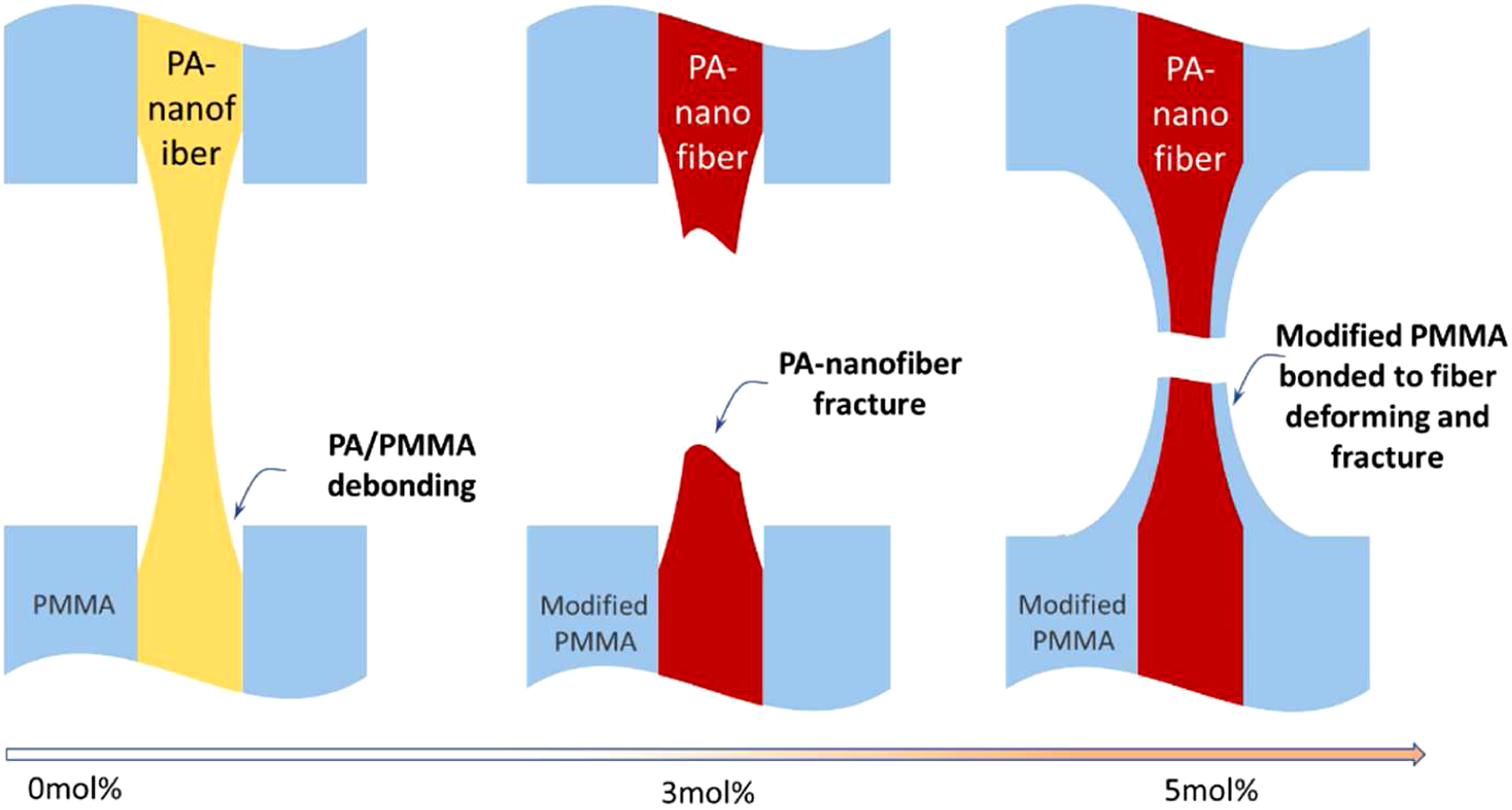
Conclusion
A new attempt has been carried out to apply the electrospun nanofiber to enhance the interlayer toughness of the CFRTP. And based on previous research experience, the different molar concentration of HEAA was copolymerized with MMA, aiming to improve the interfacial adhesion of CF/matrix and nanofiber/matrix in CFRTPs interleaved by PA veils. The data of GⅠ and GⅡ demonstrated that the interleaved PA veils have a considerable improvement in interlaminar fracture toughness of the CFRTPs laminate system. But with the increase of HEAA polymerization from 0 mol% to 5 mol%, the interlayer toughing effect of PA veils exhibited a characteristic of decreasing firstly and then increasing under the Mode-Ⅰ loading, which is related to the change of crack tip path accompanied by the shifting of bridging mechanism. Whereas Mode-Ⅱ loading exhibited a characteristic of increasing firstly and then decreasing, which is related to forming multilayer microcrack in nanotoughing matrix layer.
To further understand the effect of interfacial adhesion on fracture mechanism, we observed the fracture surface of the fiber layer and nanotoughing matrix layer in detail. The result showed the improvement of resin adhesion to carbon fiber and PA nanofiber. For the DCB samples, it enhanced the interfacial strength between nanotoughing matrix layer and carbon fiber layer and also greatly inhibited the CFs and nanofiber pull out from the matrix, thereby reducing the bridging effect; for the ENF samples, it effectively enhanced shear stress transmission between nanofiber and matrix, and makes the nanofibers have more effective fracture work without debonding, thereby improving the bridging quality of nanofibers. But it must be pointed out that the insufficient polymeric HEAA component also made the resin too elastic when the high content of HEAA feed in bulk polymerization, resulting in insufficient deformation strength. In summary, applying the electrospun nanofiber to enhance the interlayer toughness of the CFRTP is a feasible scheme. At the same time, the improvement of resin/fiber interfacial adhesion has different effects on fracture mechanism of CFRTP laminate under different loading modes and then affects the fracture behavior of the CFRTPs system.
Footnotes
Declaration of conflicting interests
The author(s) declared no potential conflicts of interest with respect to the research, authorship, and/or publication of this article.
Funding
The author(s) received no financial support for the research, authorship, and/or publication of this article.