
Abstract
Polyphenylene sulfide (PPS) is commonly used in automobile industry, aeronautics and space electrical–electronic components, and mechanical applications. Mussel shell wastes could be an economical reinforcement alternative for polymer-based composites. Which also gets out the environmental trouble of mussel shell wastes. To examine the effect of mussel shell wastes as reinforcing material, particulate mussel shell wastes were incorporated into the PPS matrix in different mass ratios (0, 1, 3, 5, and 10 wt%). Materials were characterized with ball on disc, scratch, solid particle erosion, hardness, and tensile tests. According to tensile test results, mussel shell reinforcement has a positive effect on elastic modulus and tensile strength of PPS. Moreover, mussel shell filling increased the adhesive wear resistance of PPS. According to scratch test results, scratch hardness value was increased, and residual penetration depth was decreased by mussel shell reinforcement. Furthermore, adding mussel shells in PPS increased the cutting volume value and the scratch behavior of PPS turn from ductile to brittle. Mussel shell waste supplementation increased solid particle erosion resistance at low particle impact angles but decreased it at right angles and those close to right angles. The erosive wear resistance of the PPS samples increased at 30° impingement angle by mussel shell reinforcement. The plastic deformation ability of PPS was decreased by adding mussel cell. As a result of this study, it is seen that usage of mussel shell wastes could be possible in the PPS matrix as a reinforcement material.
Keywords
Introduction
Thermoplastic polymers find increased usage areas for numerous industrial applications because of their recyclability, low density, high stiffness, and high strength properties. Moreover, they provide easy production of complex geometry products with various production methods.1,2 Polyphenylene sulfide (PPS) is a thermoplastic polymer which has semicrystalline structure. Sulfur atoms and phenyl rings form the macromolecule structure of its backbone.3–13 PPS shows appreciable chemical, physical, and outstanding mechanical properties such as low water absorption, flame resistance, high temperature and dimensional stability, high friction properties, high decomposition temperature, chemical and corrosion resistance, and so on.3–6,8,9,12,14–16 Due to its ascendant properties, it is used in many applications increasingly as telephone optical-fiber cable, electric and electronic, machinery, automotive, aerospace, battery industries, and so on.3,13,15,17–19 The weakness of its toughness and having high prices shortens its usage volume in industrial applications. Therefore, using cheap particle fillers to reduce final product cost and to enhance the weak specification of the polymers is a common application.3,8,14,19–24
Due to the worldwide increasing consumption of seafood and shellfish cultivation, shellfish shells wastes have become an environmental trouble. This problem brings two situations, the first is the decomposition of the organic components. Incidental to decomposition, noxious hydrocarbon gases NH3 and H2S are produced. These gases have remarkable toxicity and stink, and they are really noxious to human health. The second is the storage yard of the shellfish shells wastes which go to the propagation place of insects, flies, and mice due to the presence of moisture and dirty water. Mussel shells are by-products that are obligatory for companies to dispose of. In addition, as the volume increases, the disposal fees paid by the firm increase gradually. On the other hand, mussel shells involve a vast scale biominerals mainly of calcium carbonate (CaCO3). The mussel shell consists of 95% CaCO3 and 5% organic materials, and CaCO3 is the most common inorganic filler for polymer-based composites.
In recent years, ecofriendly, biodegradable fibers, and/or particles have been increasingly used as a filler for composite production. Thus, using of these bio-based fillers brings many advantages such as eco friendliness, low density, low cost, and so on. Bio-based fillers substitute the universal fillers.25–29
The main aim of this study is to improve the tribological and mechanical properties of the PPS and to reduce the cost of the material using mussel shell (none-commercial and must be disposed of) particle. Using mussel shell as a reinforcing agent, it is aimed to reduce both environmental pollution and production costs. To understand the effectiveness of the mussel shell particles as a reinforcement into PPS matrix, the mechanical and tribological properties of the composite samples were investigated.
Materials and method
Materials
Granular PPS was supplied from Ticona Company, Sulzbach, Germany, and the brand name of PPS matrix is Fortron®PPS 1200L. Mussel shells wastes were supplied from Varollar Company, İstanbul, Turkey.
Manufacturing of composites
At the first step, mussel shells were washed by pure water then dried in oven at 80°C for separating organic tissues from shells. Dried shells were crushed by Retsch®K200 crusher and pulverized by Retsch® PM100 grinder. Pulverized mussel shell particles with the dimensions of 25–106 µm and PPS matrix were melt mixed at various weight ratios (1, 3, 5, and 10 wt/wt%) using a twin-screw extruder which is produced by DSM XPLORE Company (the Netherlands). The size distribution of mussel shell particles according to sieve analysis is shown in Figure 1. Prepared mixtures were molded by DSM XPLORE injection machine. The melting temperature was 305°C, and rotational speed of twin screws was 100 r/min during the mixing process. The 305°C melt mixtures were injected into the mold at 80°C under the 10-bar pressure.
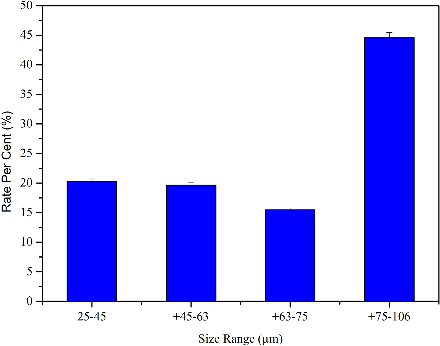
The size distribution of mussel shell particles.
Experimental methods
Shimadzu AG-X Universal Tensile Testing Machine was used to investigate the mechanical properties of samples under 5 mm/min cross head speed at ambient moisture and temperature.
Scratch tests were applied with 30 mm/min scratch speed, under 5-N loading force and along the 5-mm scratch line on micro scratch tester produced by CSM Instruments from USA. Scratch hardness, residual penetration depth, and relative cutting volume (RCV) values were determined by scratch test.
Scratch hardness values were calculated according to equation (1). This value refers to the load that the material can carry to the unit area
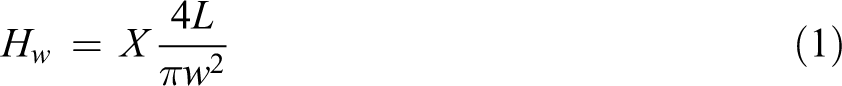
Here, “Hw” represents the “scratch hardness,” “X” is a constant number and this value is taken as 1 for viscoelastic materials, “L” represents the normal load, and “w” is the width of scratch track.30–32
RCV was calculated by equation (2). This value expresses whether the damage occurred in the form of ploughing or plastic deformation. Schematic of scratch track is shown in Figure 233,34
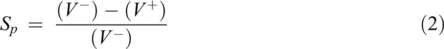
The schematic illustration of a cross section of the scratch track.
Here, “Sp” represents the RCV. It is possible to find extensive information about this calculation in the relevant references. “V−” represents the volume of the removed material during scratching by stylus. “V+” represents the volume of material that accumulates on both sides of the scratch trace as a result of plastic deformation. The RCV (Sp) could vary between “0” and “1.” Sp value of “0” corresponds to the ideal micro-plowing mechanism that shows the highest amount of plastic deformation during scratching. The Sp value of 1 corresponds to the ideal micro-chipping mechanism, which indicates that there is no plastic deformation during scratching.35,36
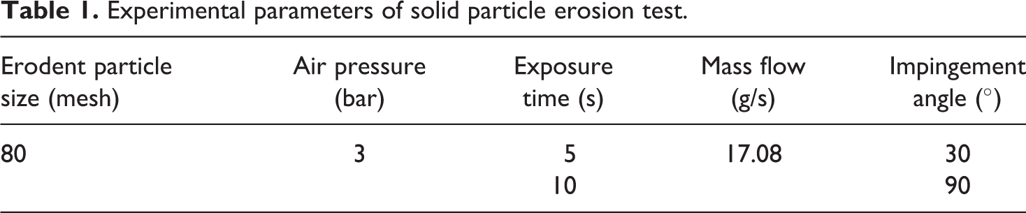
Particle erosion test rig was used for examination of solid particle erosion behaviors of the samples. Table 1 presents the experimental parameters of the solid particle erosion test. Two impingement angles were investigated, which were 90° and 30°. It is known that 90° and 30° are the impingement angles, which give the minimum and maximum erosion rates for PPS composites, respectively.37–39
Experimental parameters of solid particle erosion test.
During the evaluation of the experimental results, the method of erosion rate, which is widely used in literature and based on mass loss, is used. The method of erosion rate is calculated by the following equation
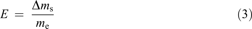
Here, “E” represents the erosion rate, “Δms” represents the mass loss of eroded sample, and “me” represents the cumulative mass of the erodent particles hit the target material during the erosion test.39,40
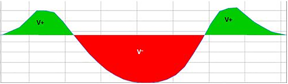
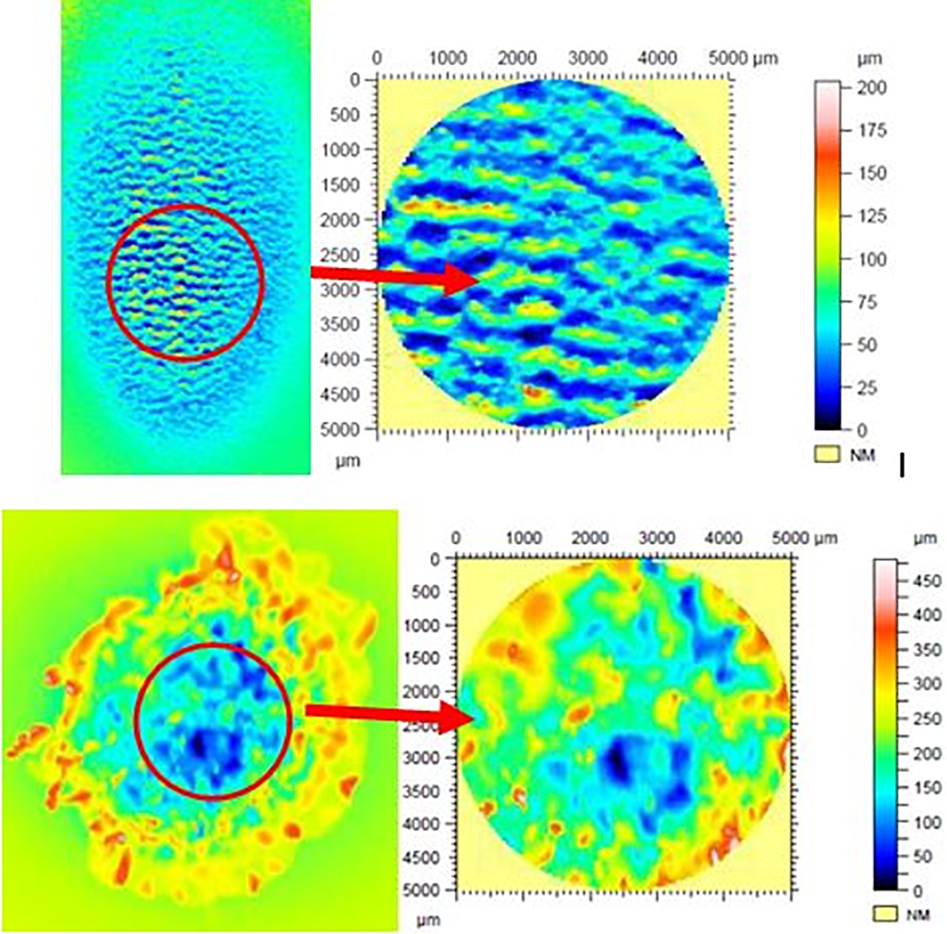
It is not always recommended to consider and to measure the wear rate as a mass loss in polymeric materials.41,42 It has been observed that the wear mechanism is not only caused by material rupture but also caused by permanent plastic deformations on the material surface. The displaced and deformed material could remain on the surface of the worn samples. In Figure 3, it is possible to see the surface topography, which is exposed to erosive wear. The surface topography consists of craters and plastically deformed peaks. The “plastic deformation rate” (PDR) of the eroded sample surface was expressed by formula (4). As seen in Figures 3 and 4, there is a crater and many peak formations (plastically deformed materials) at the sample surface after particle erosion. The PDR can be calculated by the following equation
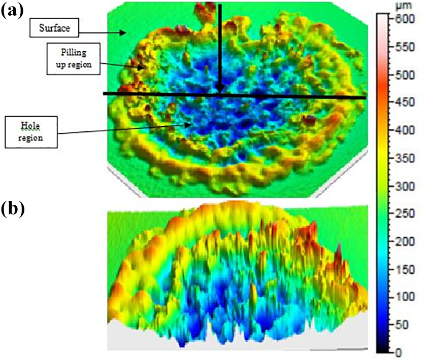
(a) Three-dimensional surface topography formed by an optical profilometer of sample surface after particle erosion and (b) three-dimensional image of the same image sectioned from the middle region.
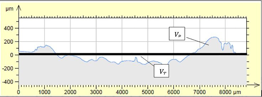
Cross section of the eroded sample.
Here, “Ep” represents the PDR, “VP” represents the total volume of the peaks formed during the particle erosion, and “VT” represents the crater volume formed on to sample surface after particle erosion (Figure 4).
As it is seen in Figure 5, average roughness values were calculated according to ISO 25178 standards to determine the roughness value of the eroded sample surfaces.
Typical wear scar after particle erosion under oblique and obtuse angle.
A ball on-disc tester (Nanovea T100 Advanced Compact Tribometer) was used for the investigation of adhesive wear tests of produced samples. The tests were performed in open air at ambient moisture and temperature. The samples were attached to the rotating disc, and an alumina ceramic ball (with a radius of 3 mm) was used as abradant, which is attached to the ball holder on the load arm. Tests were performed at 150-m sliding distance, 5-mm wear track radius, under 0.13-m/s sliding speed and 20-N normal load. During the test, the friction coefficient values and friction force between abradant ball and sample were measured and recorded. Measurement of wear tracks was performed using Nikon SMZ 745T microscope, produced Nikon from Tokyo, Japan, and the calculation of wear volume (equation (3)) of samples was made according to ASTM G99 test standard by assuming that there was no significant ball wear
Here, “V” represents the worn volume (mm3), “R” represents the radius of the wear track (mm), “D” represents the width of wear track (mm), and “r” represents the radius of the ceramic ball (mm).
Surface morphology of the worn samples was determined by Nanovea 3D Non-Contact Profilometer PS50 (Nanovea, Irvine, California, USA). Then, 20 × 20 µm2 area was scanned for each parameter with profilometer under 0.1 mm/s velocity. Calculation of eroded area volumes, 3D surface topographies, and profile roughness were evaluated by Mountain Software Version 6.2.7487 (Digital Surf, Besançon, France).
Scanning electron microscopy (SEM) analyses were used to investigate the surface morphologies of the wear debris and traces and to evaluate the matrix–filler adhesion after the adhesive wear tests. SEM analyses were performed by JEOL JCM-6000 model scanning electron microscope (JEOL, Tokyo, Japan). The surfaces that are investigated are sputter coated with gold before analysis to provide conductivity.
Results and discussion
Mechanical properties
As seen in Figure 6(a), the tensile strength of the 1-wt% mussel shell-reinforced material is remarkably increased. The tensile strength values of 1-wt% reinforced materials reached approximately 82 N/mm2, which correspond the 8% increase compared to neat PPS matrix. This increase shows the favorable synergistic effect of mussel shell particles on tensile strength. On the other hand, additional mussel shell reinforcement over 1 wt% results in lower tensile strength. The decrease in tensile strength value with mussel shell reinforcement continued up to 10-wt% reinforcement. The rigid particle reinforcement reduces the molecular mobility in the polymer material, and the high strength of the particle–polymer interface increases the deformation resistance of the material. However, the additional amount of particles in the compound exceeds a certain limit value, and the particles yield to agglomerate and may behave like one large particle instead of many particles, which also increase the stress concentration. In this case, instead of a plurality of interfaces, a single grip surface is formed. Note that 10% mussel shell-reinforced material has the same tensile strength value with the neat polymer.
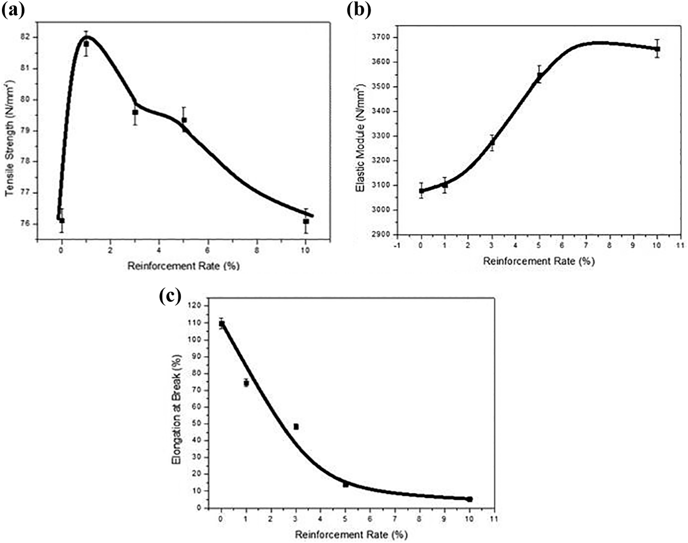
Mechanical test results: (a) tensile strength, (b) elastic modulus, and (c) elongation at break.
Elastic modulus value results are shown in Figure 6(b). As expected, an increase in the mussel shell reinforcement increased the elastic modulus of the material. The tendency to increase in the elastic module value decreases when the particle content of approximately 5% is exceeded. The 10-wt% reinforced PPS composites give 19.6% higher elastic modulus value than pure PPS. In other words, mussel shell reinforcement increases the rigidity of PPS due to its higher stiffness value at all reinforcement ratios. As a natural result of the increase in elastic modulus values in Figure 6(b), there is a remarkable reduction in elongation at break values (Figure 6(c)). As also seen in Figure 6(c), the mussel shell reinforcement makes the polymeric matrix much more brittle than the ductile pure PPS matrix, as reported in previous studies.25,26,35,43,44 During our study, the effect of higher particle weight fractions more than 10% was also investigated. However, it was observed that the material has become extremely fragile. Because of considering that the level of brittleness obtained is not industrially usable, the results of these reinforcement rates were not presented.
The effect of mussel shell reinforcement on hardness values is shown in Figure 7. Mussel shell reinforcement has a positive effect on hardness value. The increase in the mussel shell rate in composite results in an increase in the hardness values of composite samples. However, it should be highlighted that this increment is not very significant. The increase in hardness value in parallel with the increase in elastic modulus value is consistent with the other studies in the literature.45–47
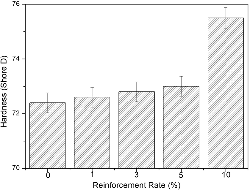
Hardness test results.
Adhesive wear results
The adhesive wear behavior of pure and mussel shell particles-reinforced PPS samples has been investigated in terms of coefficient of friction (COF) and volume loss according to ASTM G99. Worn surfaces of samples were scanned by optic profilometer. And also the surface morphology investigation and 0-s calculation of worn volumes were done by the software of the device.
The average wear volumes of five specimens are shown in Figure 8. As seen in wear volume results, there was a remarkable decrease in wear volumes. Then, 1% mussel shell particles reinforcement results in a 64% reduction in wear volume of the material. All of the composite samples exhibited a higher wear resistance than pure PPS. The wear resistance of the samples decreased with the increasing reinforcement rate. Not surprisingly, these results could be expected from the materials with a higher hardness, higher strength, and higher modulus of elasticity than pure PPS. At the 10% reinforcement rate, the adhesive wear volume of the composite shows 50% lower wear volume than neat PPS.
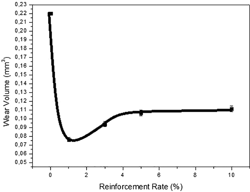
Wear volume of samples by adhesive wear.
Figure 9 shows the change in the COF values of the samples as a function of the distance. According to the graph, COF of pure PPS material reached the steady state after a very short sliding distance, and the COF shows constant value during the test period. However, the composite samples show an initial short steady stead period, and after this period, COF values reach approximately three times, because the wear mechanism changes from adhesive to abrasive wear behavior. In general, as expected, an increase in the reinforcement rate reduced the COF. On the other hand, reinforced composites’ steady-state regions during adhesive wear are very short. The authors believe that as a result of pulled out particles, wear mode tends from adhesive to three body abrasive wear.
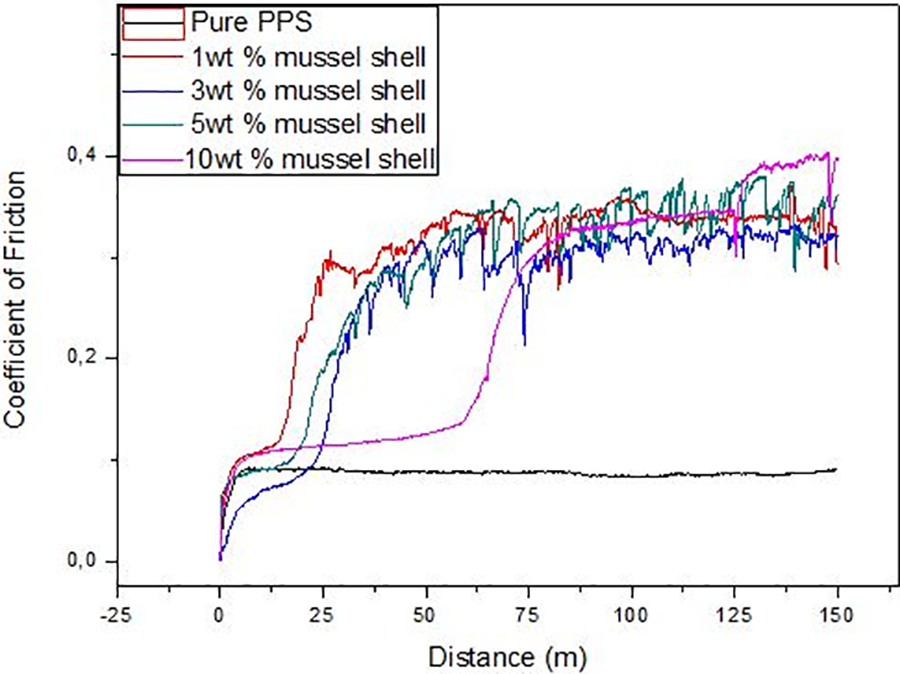
Coefficient of friction values during adhesive wear process.
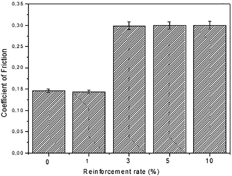
The COF values at the steady-state stage are more important for designers. Figure 10(a) represents the COF values of the samples at steady-state region. At reinforced composites after a short steady-state region, friction coefficient values are remarkably increased approximately 3.5 times. As a result of these analyzes, it is possible to say that the adhesive wear behavior and wear resistance of the composites is closely related to the particle ratio. Matrix material loss, mussel shell wear, and mussel shell debonding at the interface are the three major mechanisms that expand the energy during wear. It is well-known that whereas a weak interface provides energy absorbing modes of failure, making the material more energy absorptive, a strong interface results in a more rigid but brittle composite structure.48,49 For this reason, after debonding of mussel shell particles, wear mechanism returns from adhesive to three-body abrasive wear mechanism. This situation could explain the main mechanism of the increase in the wear rate and COF with increasing particle reinforcement rate.
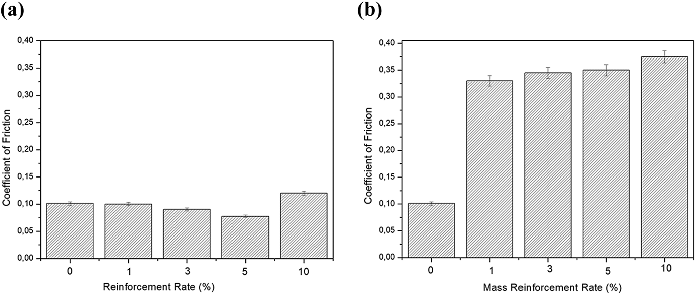
Average coefficient of friction values (a) at steady-state stage and (b) after abrasive wear start.
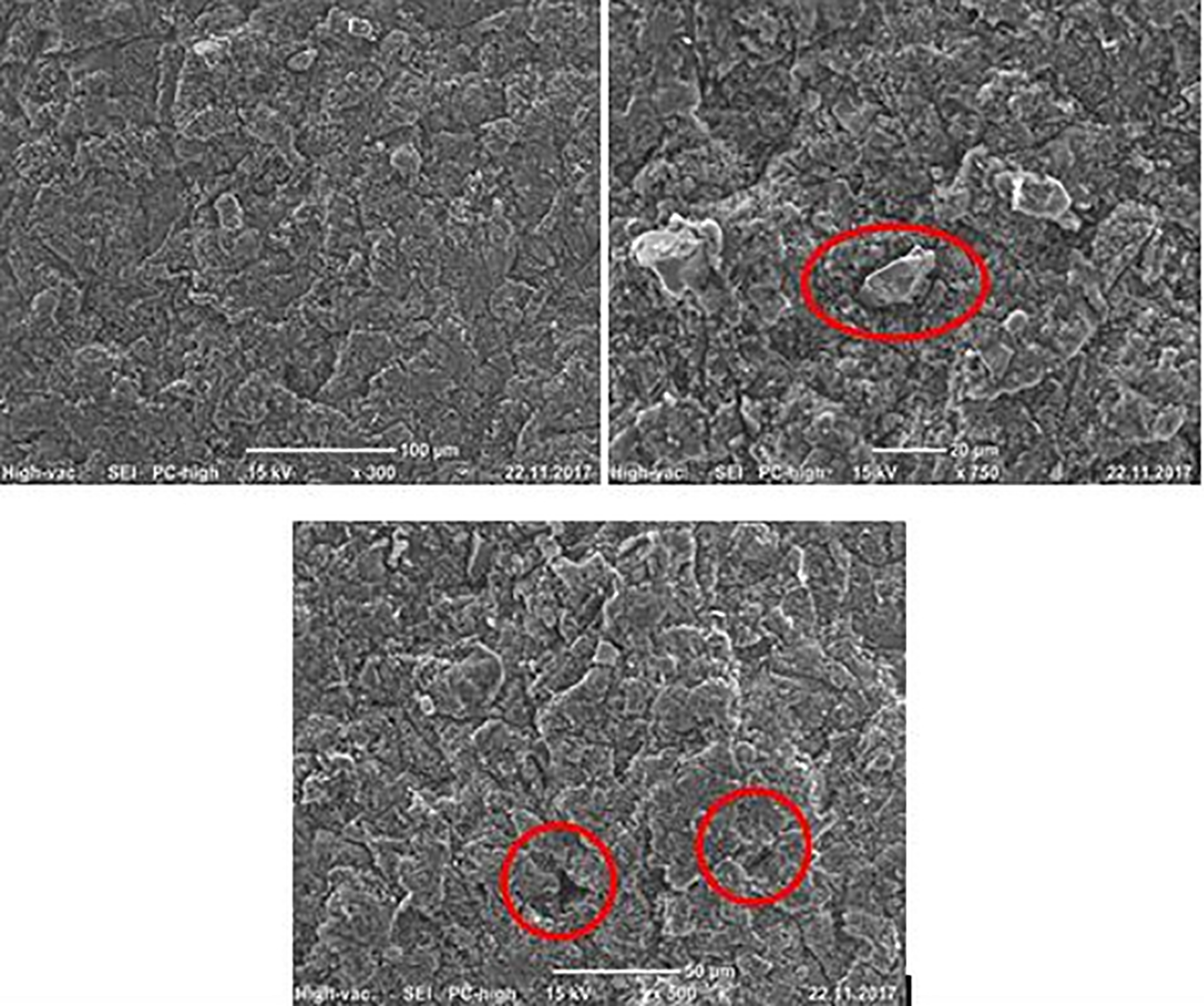
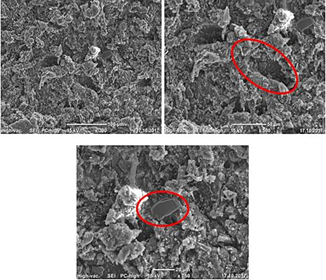
SEM studies of worn surfaces after adhesive wear test of pure PPS and 10-wt% mussel shell filled with PPS composites are shown in Figures 11 and 12, respectively. Typical adhesively worn-unreinforced polymer morphology is investigated at the surface of the samples. Typical counterpart (ball) traces can be seen which could be formed by micro-cutting and micro-ploughing mechanisms. There is no cavity, and debris formation is investigated on the surface of the samples despite the higher magnification in Figure 11. On the other hand, as mentioned above, at higher reinforcement rates, the COF of the materials get higher and it is possible to investigate the surface morphology of the three-body abrasion mechanisms (Figure 12). As a result of particle pullout mechanisms, pulled out particles behave as a third rigid part which results in abrasive wear mechanisms (Figure 12). It is possible to see deboned particles, ploughed traces, tears, and debris formations, especially at higher magnification on Figure 12.
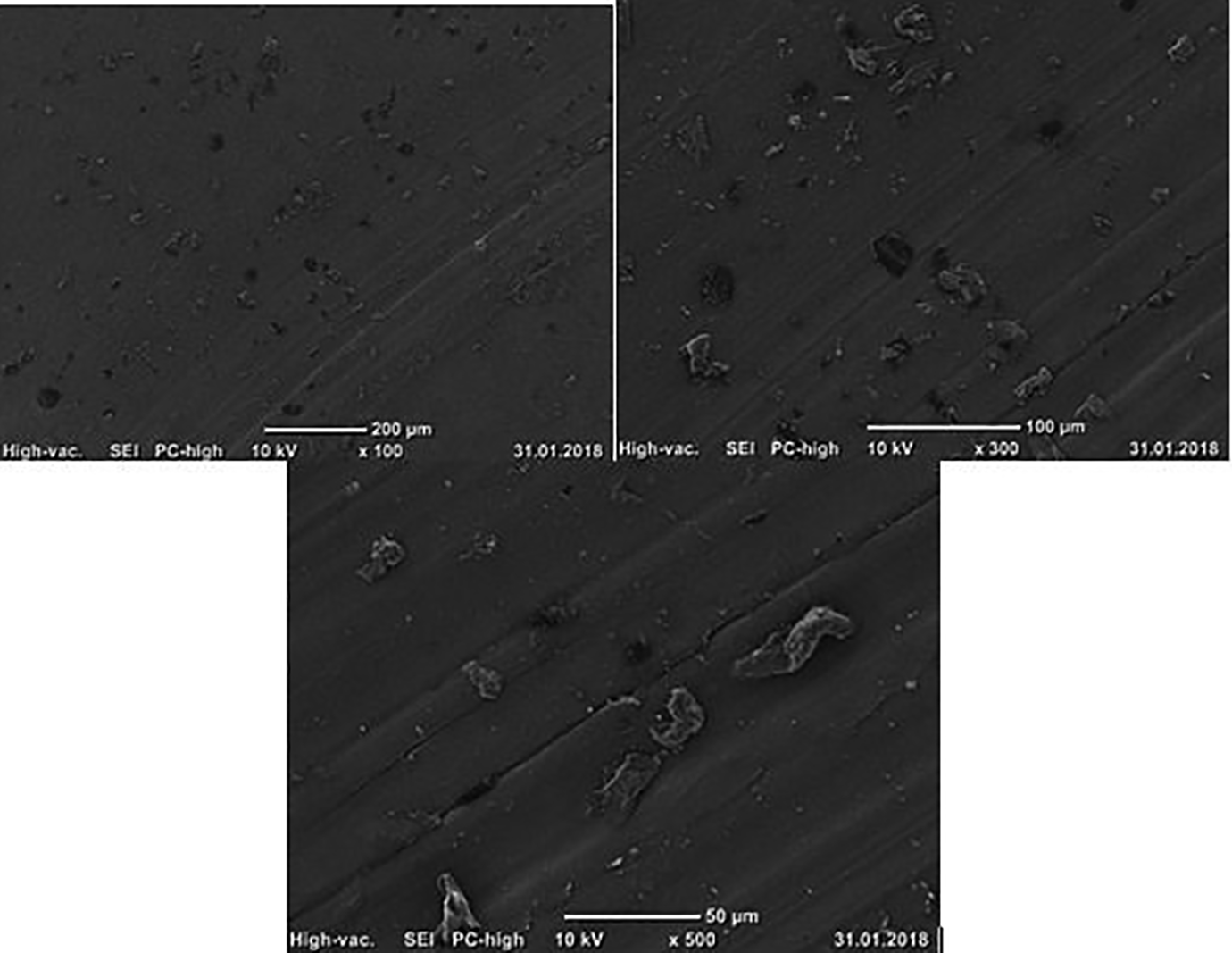
Scanning electron microscopic photos of worn surface of pure PPS.
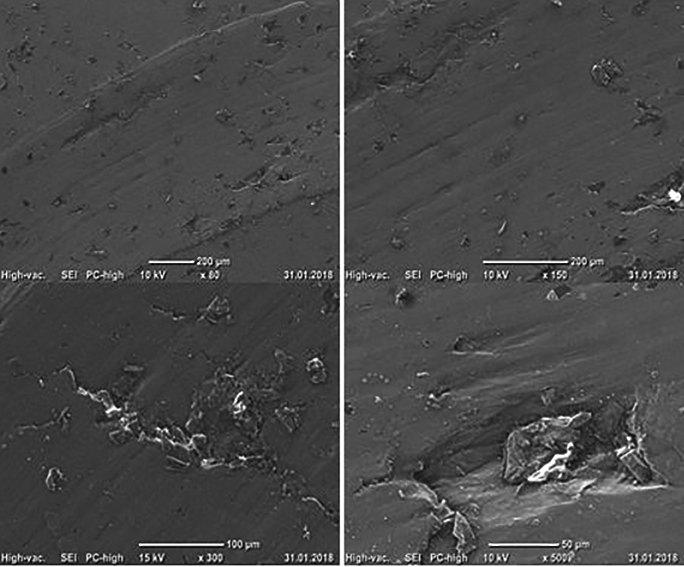
Scanning electron microscopic photos of worn surface of 10-wt% mussel shell-reinforced PPS.
Scratch test results
As mentioned in Figure 7, hardness of material of the material increases with an increase in particle rate. However, the scratch hardness values of the materials are more reliable than the hardness values in tribological characterization of the materials. Scratch hardness is generally used to define the resistance of the material against to scratch. While materials with a higher scratch hardness are expected to be greater resistance to scratch and abrasion damage. According to Figure 13, an increase in the mussel shell rate in composites increases the scratch hardness value of the composites. Because of the hard nature of mussel shell, an increase in mussel shell rate in polymer matrix increases the rigidity and resistance to penetration of counterpart of the composites. This situation results in an increase in scratch resistance. The Young’s modulus is a serious indicant of the scratch process, particularly for indentation process. Thus, reinforced polymer shows higher resistance against scratching. Figures 10(b) and 9 show that scratch resistance has a direct relationship with modulus values. An increase in modulus values results in improved scratch hardness values. Figure 14 also shows that there is a direct relationship between scratch hardness and residual penetration depth. An increase in the mussel shell reinforcement rate results in a decrease in the residual depth values.50–53
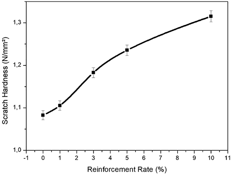
Scratch hardness of the samples.
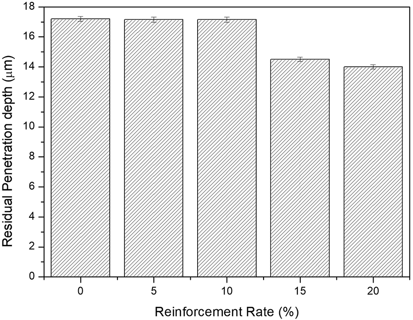
Residual depth of the samples.
The RCV results are shown in Figure 15. RCV is one of the important parameter formation mechanism of the scratch damage. Considering that the scratched material is polymeric, a scratch could be formed with micro-cutting, micro-ploughing, and plastic deformation. As shown in Figure 15, the increasing reinforcement rate of the mussel shell in PPS results in the RCV value from 0.34 to 0.63. The RCV value of 0.34 means that the unreinforced polymer matrix is highly ductile, because it is measured that the volume of accumulated material as a result of plastic deformation (V+) is considerably higher than reinforced materials. On the other hand, an increase in the particle reinforcement rate in the material results in high RCV values, which indicates that the material becomes more rigid. At higher reinforcement rates, there is an increase in the removed material below the original sample surface line (V+) and a decrease in the volume of accumulated material as a result of plastic deformation (V+). The RCV value increases with increasing particle rate and reaches an asymptotic value around 0.64. It means that the plastic deformation ability of the samples decreases and samples become much brittle. 53
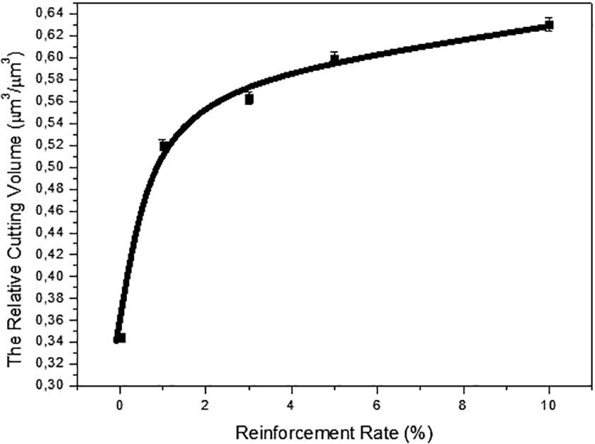
The relative cutting volume results.
The average COF measured as a result of scratch test is shown in Figure 16. The average COF value of the samples is increased by reinforcement rate approximately two times. It was determined that the surface roughness of the scratch grooves worsened with the mussel shell reinforcement. To understand the main source of the increment in friction coefficient during the scratch testing, friction force/COF graphs and result of optic profilometer scans of the pure PPS and 10% mussel shell-reinforced composite are examined in Figures 17 and 18.
Average coefficients of friction values of scratch tests.
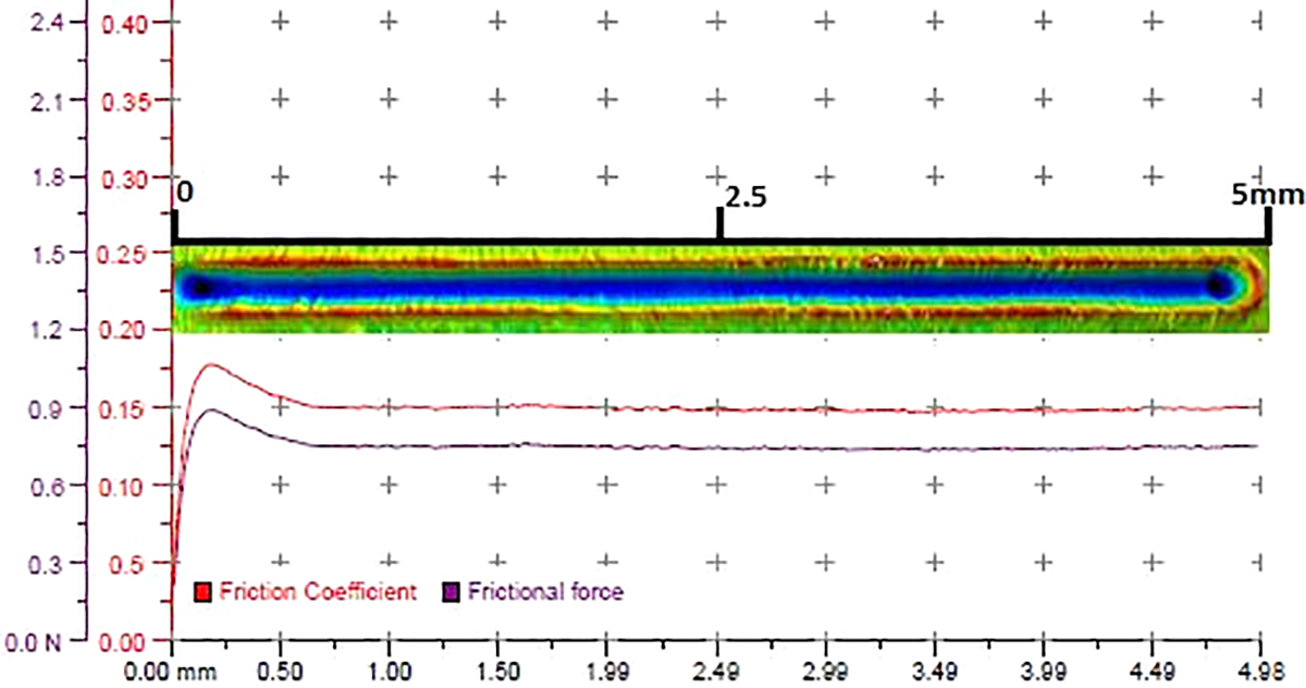
Optic profilometer scan and friction force of pure PPS during scratch testing.
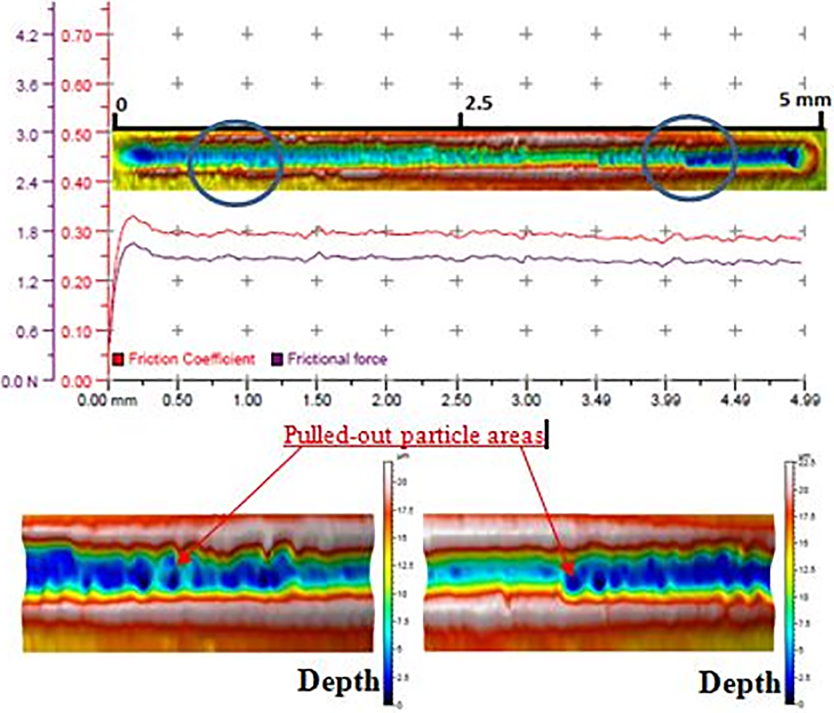
Optic profilometer scan and friction force of 10-wt% mussel shell-reinforced composite during scratch testing.
As it is seen in Figures 16 and 17, pure PPS has a lower COF (around 0.15) during the scratch testing, which gives smooth and slippy surface morphology. On the other hand, 10-wt% mussel shell-reinforced sample has a higher COF (around 0.3) during the scratch which gives higher rough and dimpled surface morphology during the scratching (Figure 18). This rough and dimpled surface morphology can be explained with a displacement of reinforcement particles. The increase in friction coefficient indicates the scratch tip–sample interaction. The friction coefficient increases when the scratch tip forced the particles to remove from the polymer matrix. Increase in the number and the strength of interface between particle and matrix results in an increase in the friction coefficient. At higher particle reinforcement rate, because of the dislocation (pullout) of the particles from polymer matrix results in high friction coefficient and rough surface morphology at the scratch surface. Displaced particle behaves as abrasive particles, which results in higher wear and rough surface morphology.
Figures 17 and 18 show the synchronized friction coefficient and scanned surface morphology . As it is seen clearly, there are lots of peaks in the COF curves. Figure 17 shows a very smooth force–displacement curve. Also the scanned scratched track is illustrated. When we compare two of them, it is possible to say that there is smooth scratched surface without particle pullout. In Figure 18, it is possible to see peaks on the force–displacement curve. It is clearly shown that force peaks occur as a result of the stylus interaction with particle. Pulled out particle areas are match up with force peaks on the force–displacement curve.
Solid particle erosion results
Particle erosion resistance of the materials is generally represented in terms of erosion rate. The term erosion rate is based on weight loss of eroded samples. Figure 19 shows the erosion rate value of samples. According to Figure 19, at an impingement angle of 30°, 1-wt % mussel shell reinforcement rate in PPS matrix gives minimum erosion rate. Increase in reinforcement rate in PPS matrix gives the higher erosion rate. There is no weight loss at the eroded sample at an impingement angle of 90°, but on the contrary, there is an increase in the weight of target material.
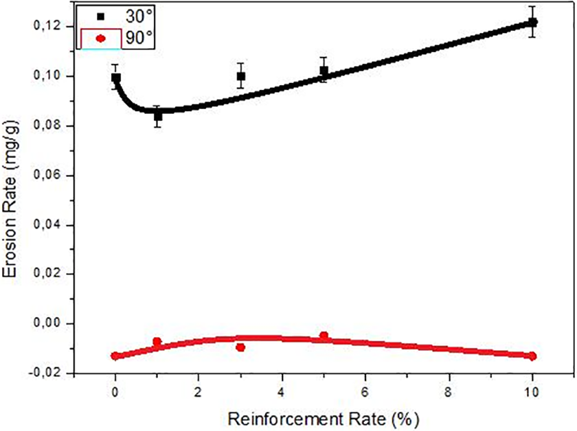
Erosion rate results of samples.
It is known that erosion rate is one of the important parameters, which indicates the material characteristics against the particle erosion. But some results, which similar to Figure 19, are unable to explain the erosion behavior of the materials. Because, embedded erodent particles are ignored in erosion rate calculations. Especially at an impingement angle of 90° and the angles closer to these angles, erosion rate values couldn’t give the quantitative real particle erosion/material interaction.
On the other hand, eroded and deformed material surface could be explained also with volumetric loss or volume of crater formations. To understand the result of erosion rate, eroded material surfaces were scanned by optical profilometer and the wear volumes on the target surface were determined. Then, using formula (2), the amount of plastically deformed material on the surface was calculated. Wear volume results after particle erosion are shown in Figure 20. According to Figure 20, the wear volume decreases with increase in the mussel shell rate in PPS at an impingement angle of 30°. In other words, erosive wear resistance of the PPS samples is linearly increased at 30° impingement angle by mussel shell reinforcement. Volumetric erosion loss (mm3) 50% decreased by 10-wt% mussel shell reinforcement compared to pure PPS. In contrast, the wear volume increases with the increase in the mussel shell rate in PPS at an impingement angle of 90°. In other words, erosive wear resistance of the PPS samples is affected negatively, at an impingement angle of 90° by mussel shell reinforcement. Furthermore, samples have higher volumetric loss at an impingement angle of 30° than at an impingement angle of 90° for all filler loading rates. The increment in reinforcement rate increases the eroded volume at an impingement angle of 90°, while decreasing the particle impingement angle of 30°. It is possible to say that the samples are getting more rigid with particle reinforcement, and at an impingement angle of 90°, samples with a higher rigidity give higher volume loss. On the other hand, particle reinforcement makes the material with higher strength result in higher particle erosion resistance. And as a result of this situation lower volumetric loss values were achieved with an increase in the particle erosion rate.
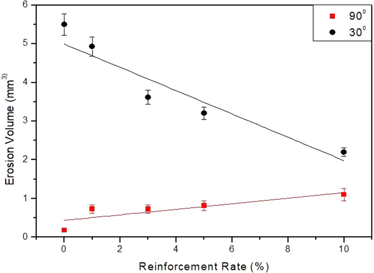
Erosion volume of eroded samples.
PDR results are shown in Figure 21. PDR of the samples at 90° impingement angle is remarkably higher than 30° impingement angle. When the results are examined, mussel shell reinforcement takes the composite material into a brittle structure, which remarkably restricted the plastic deformation ability of the samples. This characteristic situation is supported by tensile and scratch test results.
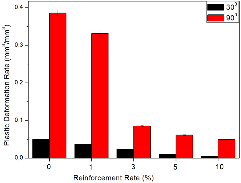
Plastic deformation rate.
Figure 22 shows the average roughness values of eroded samples. According to roughness results, while surface roughness of pure PPS is independent from the particle impingement angle, surface roughness of composite samples has higher value at an impingement angle of 30° than at an impingement angle of 90°.
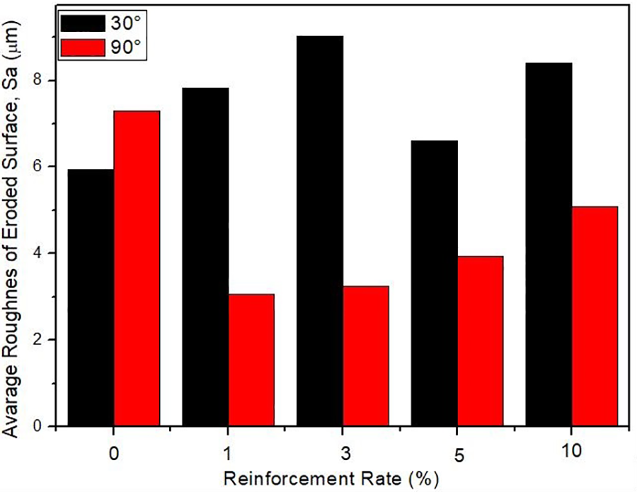
Average roughness value of eroded surface samples.
Figures 23 and 24 show the SEM photos of the surface after particle erosion for 10-wt% mussel shell-reinforced composite samples which were eroded at 30° and 90° impingement angles. Embedded erodent particles, pounding traces, and regional holes can be clearly seen in Figure 23. In Figure 24, micro-cutting, tears, and micro-ploughing traces on the surface are seen clearly. In addition, some filler particles could be seen on the surface owing to sweeping of the matrix around the particle.
Scanning electron microscopic photos of 10-wt% mussel shell-reinforced samples eroded at 90°impact angle.
Scanning electron microscopic photos of 10-wt% mussel shell-reinforced samples eroded at 30°impact angle.
Conclusion
The tensile strength values of 1-wt% reinforced materials reached approximately 82 N/mm2, which corresponds the 8% increase compared to neat PPS matrix. On the other hand, the 10-wt% reinforced PPS composites give 19.6% higher elastic modulus value than pure PPS. In other words, mussel shell reinforcement increases the rigidity of PPS due to its higher stiffness value at all reinforcement ratios. Particle reinforcement makes the material very brittle. The elongation at break value of neat polymer is approximately 11 times higher than 10% particle-reinforced composites.
The 1% mussel shell particles reinforcement results in a 64% reduction in wear volume of the material. All of the composite samples exhibited a higher wear resistance than pure PPS.
Mussel shell reinforcement has a positive effect on scratch resistance of PPS. Scratch hardness value was increased 28.6%, while penetration depth was decreased 18.6% by adding 10-wt% mussel shell. The RCV results ascended from 0.34 to 0.63. It means that the samples become much brittle and the plastic deformation ability decreases with increasing mussel shell reinforcement rate in PPS.
According to the erosion rate method, the increase in the rate of mussel shell in PPS decreases the erosion resistance of PPS. However, the failure of that result is obtained by optical profilometer analysis. The erosion rate method has ignored density differences between matrix and filler and the occurrence of plastic deformation. These factors were determined in optic profilometer photos, and calculation of worn volumes was made by optic profilometer. These results show that solid particle erosion resistance of PPS increases by mussel shell reinforcement. Worn volume of 10-wt% mussel shell-reinforced samples was decreased by 50% compared to pure PPS at 30° impingement angle. Pure PPS and all composite samples were less eroded at 90° impingement angle than 30° impingement angle, and wear behavior of PPS changes from ductile to brittle by mussel shell reinforcement. When the SEM photos are investigated, peeled reinforcing particles and tear traces are seen at 30° impingement angle. Moreover, embedded and beaten erodent particles on surface are seen at the 90° impingement angle.
According to this study, it is found that usage of mussel shell wastes as a filler material to produce low cost/high-performance PPS-based products could be possible. In this way, environmental pollution caused by the waste mussel shell will be prevented.