
Abstract
The heat generated within thermoplastic carbon composite laminates during induction welding can be attributed to one, or a combination of the three heating mechanisms discussed in the literature: (i) Joule heating of fibers; (ii) Joule and/or dielectric heating of polymer; and (iii) fiber-to-fiber contact resistance heating. The answer to the question, which of the three heating mechanisms is most dominant, remains open. This research aims to provide an answer to this question through finite element simulations using both an in-house developed numerical Whitney-elements based toolbox for induction welding simulations (WelDone), and the commercially available software, ANSYS Maxwell. The simulations are done at two levels; first, using WelDone laminate-level simulations are performed to see in which direction: fiber-, transverse to the fiber-, or thickness direction, most of the heat was generated; and second, ANSYS Maxwell was used to simulate the solid loss on a microscopic, inside fiber and resin, level with and without the presence of resin. In the latter series of simulations, contact between fibers in different layers was explicitly modeled. The numerical simulations revealed that on the laminate-level most heat is generated in the fiber- and thickness directions. The former coincides with Joule heating of fibers, while the latter can be attributed to either Joule heating of polymer and fiber-to-fiber contact resistance heating, or both. The fiber level simulations, however, revealed that both fiber-to-fiber contact and no-fiber-to-fiber contact conditions have a significantly small effect on the solid loss compared to presence of resin. Based on the latter, the heat generation in the thickness direction was attributed to a second heating mechanism; Joule heating of polymer. It must be noted that the dielectric heating of polymer was ignored due to the relatively low operating frequency at which induction welding takes place.
Introduction
Carbon fiber reinforced thermoplastic polymers (CFRTP) can play a significant role in the next generation of structure in both the automotive and aerospace industry. Compared to thermoset composites, (i) thermoplastic polymer resin systems offer better damage tolerance, and (ii), thermoplastics composites can benefit from the ability to locally heat, melt, and re-solidify components to create fusion bonded, fastener-free assemblies. 1 The selected method to fusion bond the thermoplastic composites in this research is induction welding as it has multiple benefits when compared to resistance and ultrasonic welding: (i) no contact between the heating element and part is required; and (ii) no need for susceptors when using CFRTP with plies in different orientation. 2
The principle behind induction welding is explained by various researchers and groups in literature,1–18 however, a brief explanation is given here for the reader’s convenience. To induction weld, an alternating-current (AC) flows through a coil, this produces an alternating electromagnetic (EM) field in and around the coil (as discussed by Faraday’s law) including the CFRTP parts. The EM field results in closed loop currents (eddy currents) and fields in both the fiber and polymer of the CFRTP parts. Compared to isotropic materials, the eddy currents generated in a composite material are more complex, however it is the eddy currents which cause energy losses and, therefore, heating in the composite laminate. The generated heat will locally melt thermoplastic polymer allowing a cohesive bond between two thermoplastic composite laminates. The induction welding methodology is illustrated in Figure 1.
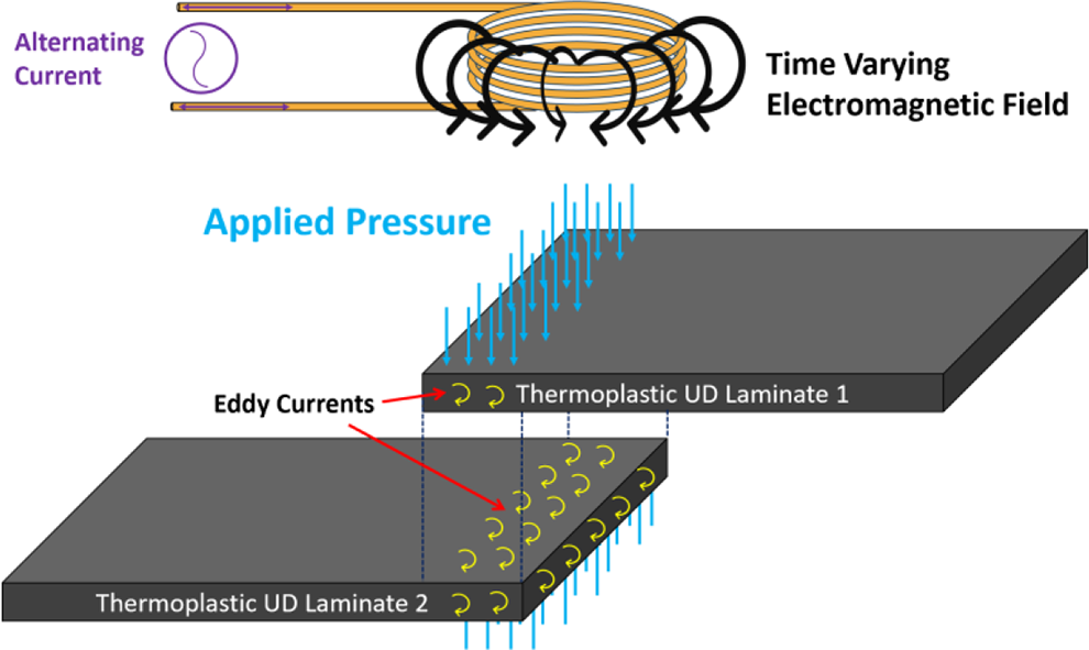
Induction welding diagram for thermoplastic unidirectional laminates.
Induction welding differs from the more “traditional” forms of welding of thermoplastics; (i) friction welding; parts are welded by generating heat by contact resistance (friction) at the interface of the components (common in pure polymers, or short fiber reinforced polymers); (ii) electrical resistance, a conductive mesh is placed at the interface between the components and heat is generated passing a current through the conductive mesh, this however, introduces a foreign material at the interface which is undesirable; (iii) ultrasonic welding, high-frequency ultrasonic acoustic vibrations are used to weld components together.
For the application of induction welding it is important to understand: (i) how eddy currents are generated in the CFRTP parts; (ii) the strength and profile of the eddy current; and (iii) the relation between the eddy currents and heat generation. Heating can occur due to (a) Joule heating of fibers, Figure 2(a); (b) Joule and/or dielectric heating of polymer (it is important to state that the dielectric effects were ignored in the research), Figure 2(b); (c) fiber-to-fiber contact resistance heating, Figure 2(c); or due to any combination of the three mechanisms. 4
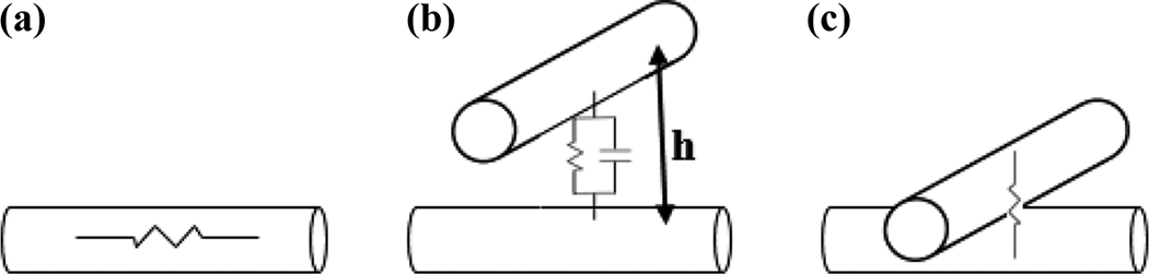
Induction heating mechanisms (a) Joule based fiber heating, (b) Joule and/or dielectric polymer heating, (c) contact resistance heating.
At the start of this research it was unclear which, or which combination of the three heating mechanisms would dominate. Literature does not provide a clear answer to this question, some literature10–12,16–18 suggest fiber-to-fiber contact heating playing a significant role while other literature4,5,7–9,13–15 indicate differently, and point toward the resistivity of the fiber and polymer. This manuscript, therefore, aims to clarify which heating mechanism or which combinations of mechanism are dominant using laminate-level and fiber level numerical simulations.
Numerical simulations on the laminate-level
A brief overview of the theory and implementation of the in-house developed toolbox WelDone is discussed here, however, the authors recommend the reader to consult8,9 for a more detailed explanation of the numerical toolbox, and for experimental validation work.
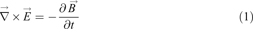
The fundamental mechanism of induction welding is heat generation in the substrate from induced eddy currents. The induction of currents is described by Faraday’s law, which implies that an alternating magnetic field
Both

where

Some aspects of the volumetric heat equation require a more detailed explanation. The electric current density

As mentioned earlier, the AC results in an alternation magnetic and electric field, therefore, the complex-valued representation is useful and frequently used in the analysis of induction welding process. The complex notation is maintained for all the calculation steps, until the volumetric heat
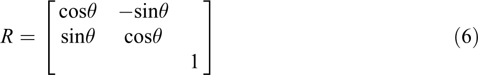
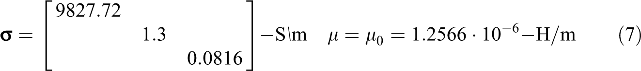
II. The 3D electrical conductivity tensor is a material property that is obtained experimentally by measuring the resistance of composite material in the principal directions; the fiber- (1-), transverse to the fiber- (2-), and thickness (3-) direction. It is assumed that the off-axes terms were equal to zero, and the diagonal terms represented the electrical conductivity in the 1-, 2-, and 3-direction, respectively. The electrical conductivity values were determined by measuring the resistivity for consolidated unidirectional (UD) laminate consisting of only 0° layers in the 1-, 2-, and 3-direction. As discussed in7–9 different ply orientations within a laminate are required to generate heat when using induction welding. For each ply, the electrical conductivity tensor was rotated by the ply orientation angle using:

where
The rotated electrical conductivity tensor is used in combination with the inner product of equation (3),
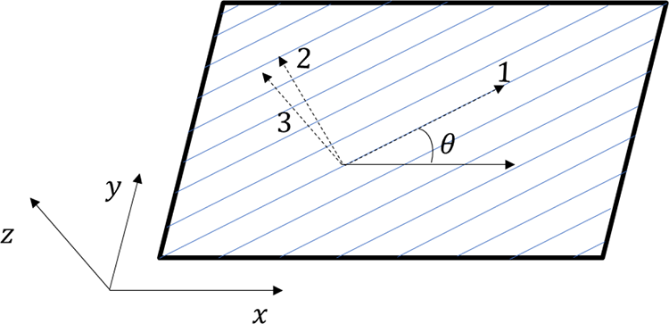
Illustration of the global (x, y, z) and local (1, 2, 3) coordinate systems.
III. As mentioned before, the 3D conductivity tensor is a material property, of which the values are based on measurements. The 3D conductivity tensor captures the different induction welding heating mechanisms. One of which, dielectric heating of the polymer is, however, not captured by the conductivity tensor though. Considering the, relative, low frequencies (below 300 kHz) used for induction welding the effects of dielectric heating are considered negligible. 1 Finally, the computational approach presented in this article models the composite material as a continuum characterized by an anisotropic, diagonal conductivity tensor, the effects of the different heating mechanisms are, therefore, captured in the numerical simulations.
WelDone simulations
The simulations were performed using an in-house developed finite element code named WelDone, which is extensively discussed in.8,9 The volumetric heat generation in the different directions was investigated based on simulations using a 10-inch (254-mm) by 10-inch (254-mm) composite laminate consisting of four layers (each 0.25-mm thick). Four different stacking sequences ((i)
Coil shape and position with respect to composite laminate.
For the first case, a
The global axes system is indicated by the x-, y-, and z-direction, see Figure 3;
The principal material axes system is indicated by the1-, 2-, and 3-direction, see Figure 3. Note, the 1-direction is always aligned with the fiber direction.
The z-axis and 3-axis are parallel; only flat laminates are considered.
From now onward only the top two layers will be given in the figures, due to symmetry the third and fourth layer are equivalent (It is important to note that the magnitude of the volumetric heat will differ between the top two layers and bottom two layer due to the different thickness distance from the coil. The volumetric heat profile, however, will be the same.) (see Figure 5) to layer one and two.
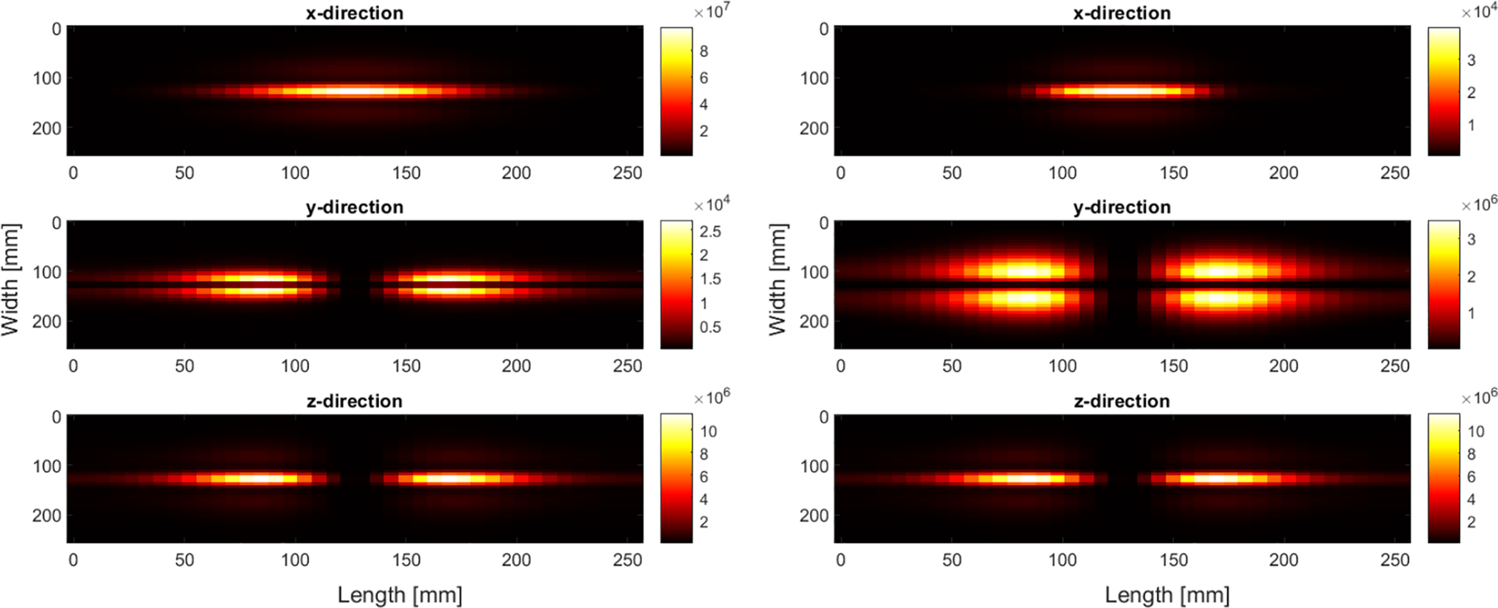
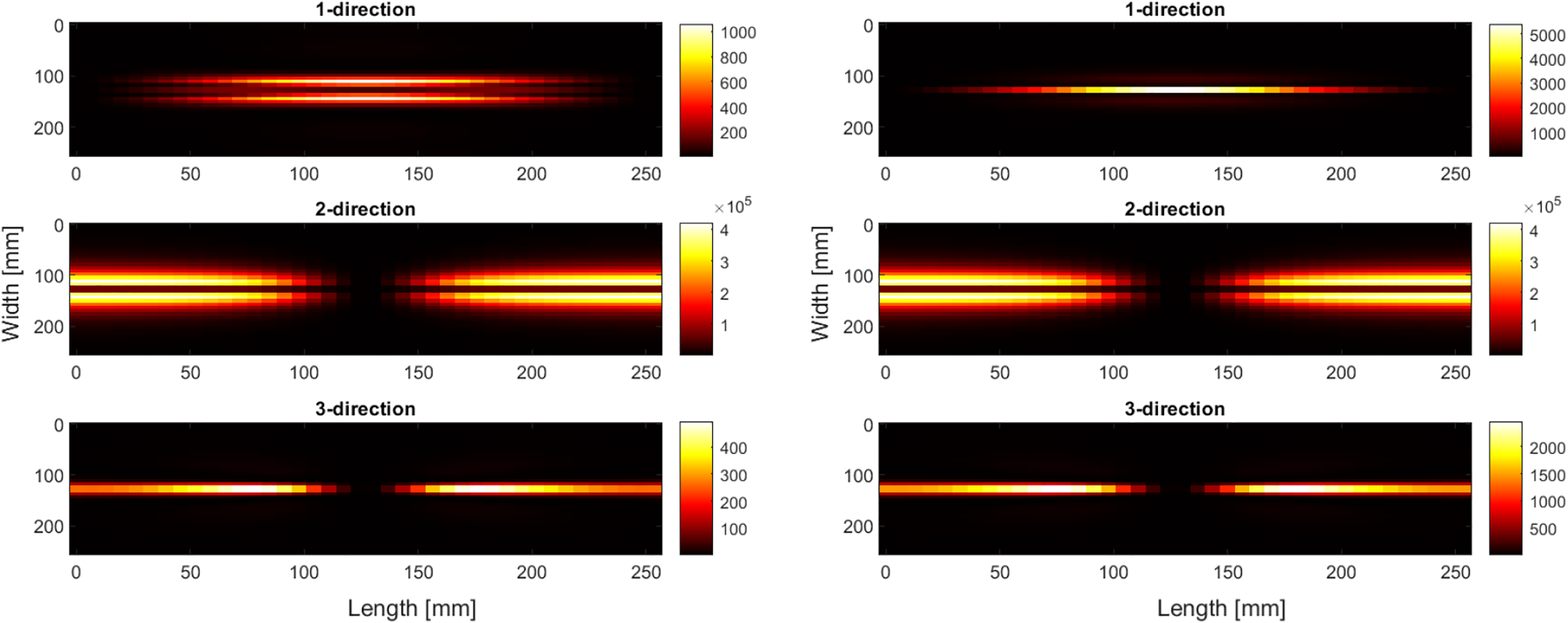
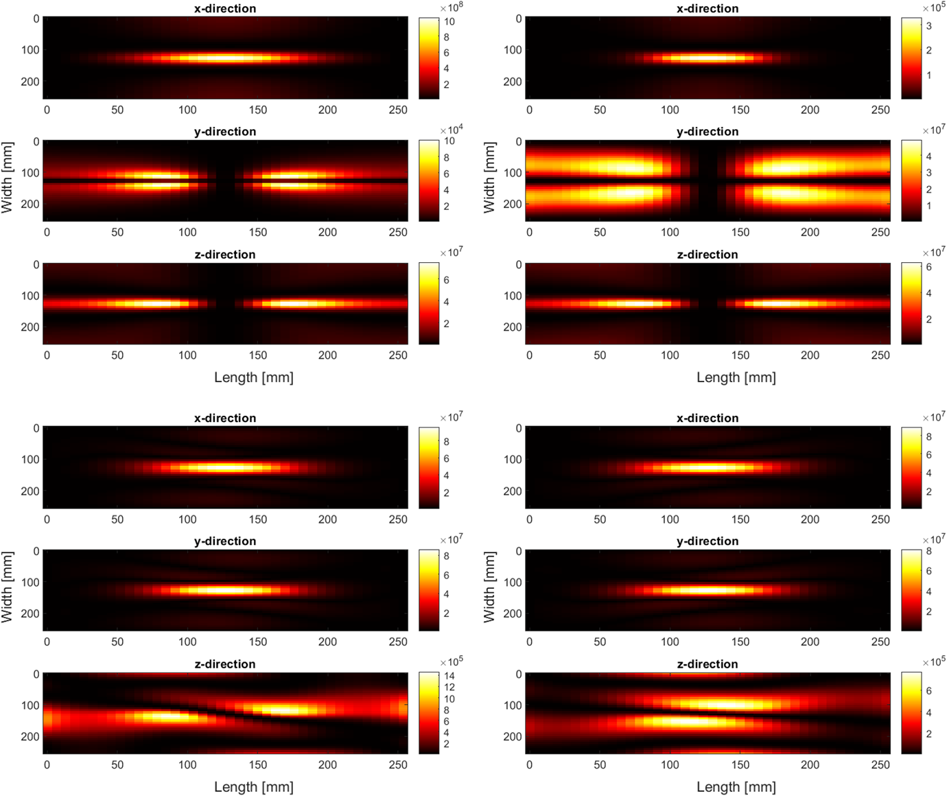
Volumetric heat generated for a
Effective heat generated for a
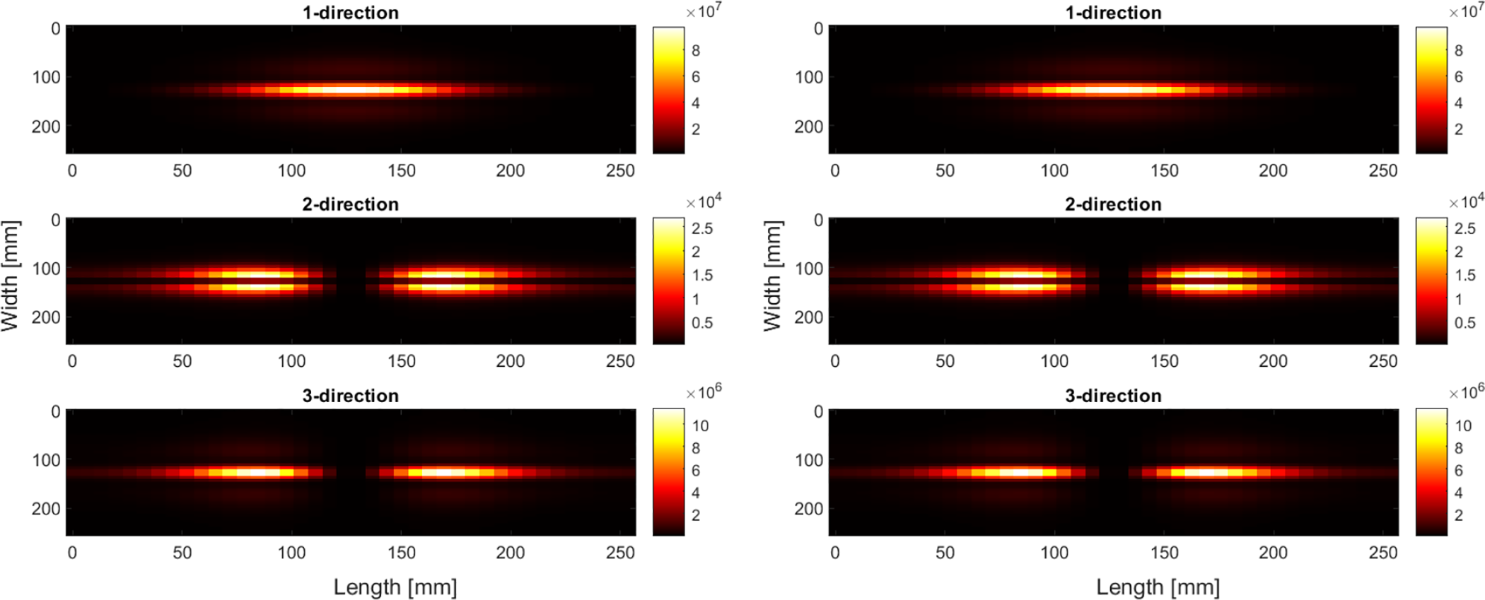
Effective heat generated a
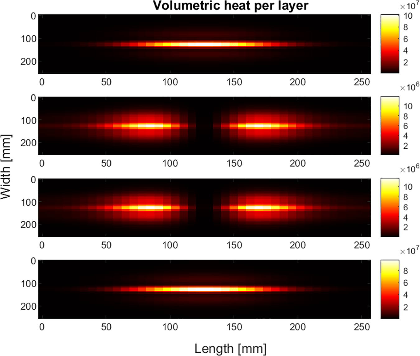
The volumetric heat shown in Figure 5 is the sum of the volumetric heat component in the x-, y-, and z-direction. To get a better understanding of which heat mechanism has a more dominant role equation (3) is expanded to include the different component of the 3D electrical conductivity tensor and the electric current density:
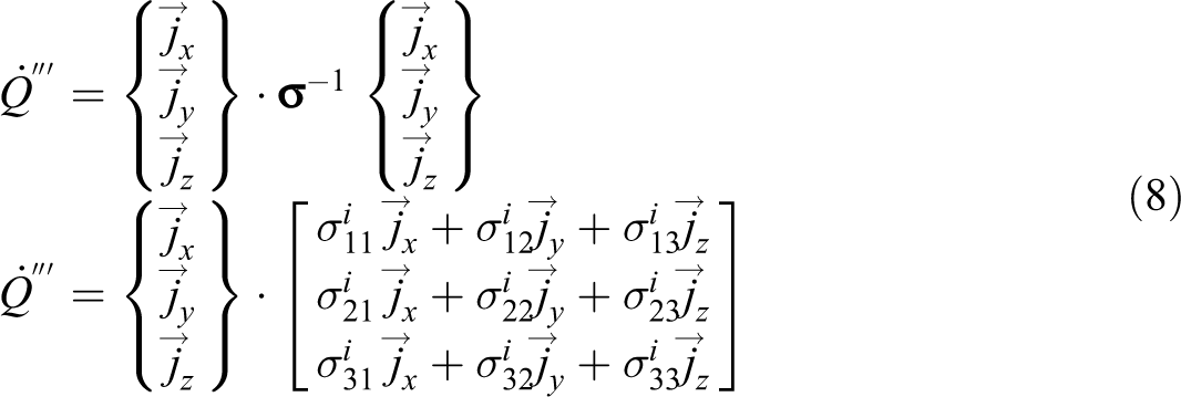
Note that indicates the dot-product, and
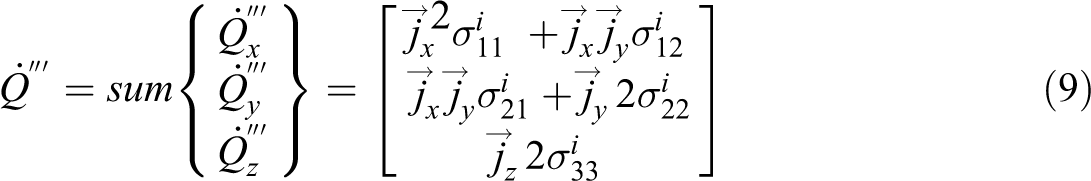
Note the volumetric heat is the sum of its components in x, y, and z; the sum of
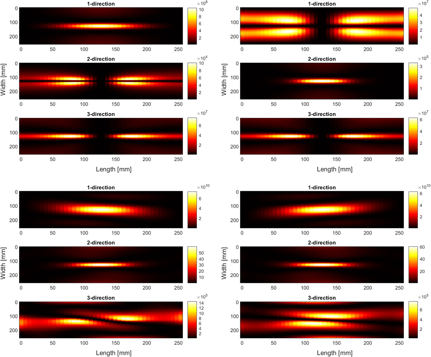
As it can be seen from Figures 6 and 7 (more clearly from Figure 7 because the heat generation is given in the material axes system), the heat generation transverse to the fiber (2-) direction is at least two order of magnitudes less than the heat generation in the fiber (1-) and thickness (3-) directions, 104 versus >106 based on Figure 7.
Based on the results in Figure 7 it is clear that heating in fiber direction is the most dominant, this can correspond to the Joule based fiber heating mechanism shown in Figure 2(a); however, there is also resin in the fiber direction, therefore, it cannot solely be attributed to Joule based fiber heating mechanism at this moment of time. The second significant contribution to the total volumetric heat generated is heat generation in the thickness direction, which could be attributed to the Joule and/or dielectric polymer heating mechanism and contact resistance heating mechanism shown in Figure 2(b) and (c), or a combination of the two heating mechanisms. At this point, no distinction to which mechanism was most dominant could be made. However, it has been reported in the literature 5 that contact between the fibers is not required to generated heat in a composite laminate. In fact, both the difference in stacking sequence and the presence of a polymer had a larger contribution to the heat generation than the contact between fibers. 5 The former, difference in stacking sequence, was investigated and the results for two four-layer laminate with all 0°- and 90°-fibers are given in Figures 8 and 9, respectively. It is important that the results given in Figures 8 and 9 represent the effective heat in the local material axes system.
Effective heat generated in layer 1 (left) and layer 2 (right), local material axes system all 0° layers.
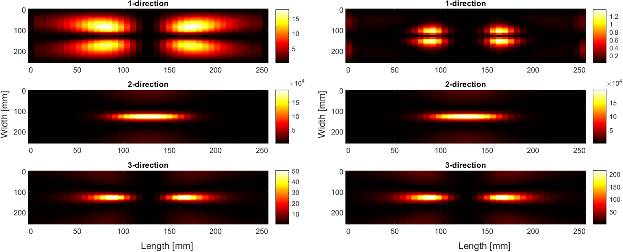
Effective heat generated in layer 1 (left) and layer 2 (right), local material axes system all 90° layers.
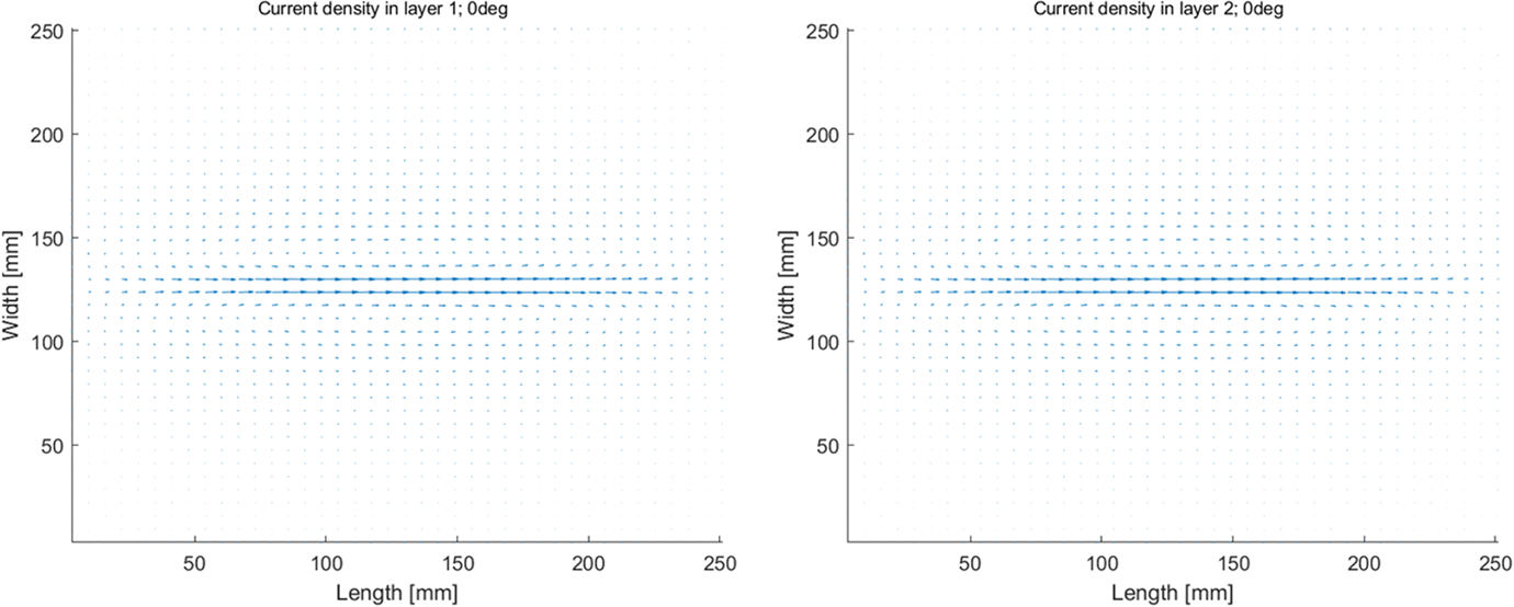
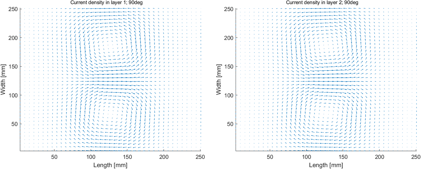
Frist, comparing Figure 7 to Figures 8 and 9 it is clear that the volumetric heat generated is significantly larger when the stacking sequence includes a change in fiber direction. Second, with all the fiber aligned in one direction (0° or 90° as shown in Figures 8 and 9, respectively), the heating is most dominant transverse to the fiber direction (the two-direction). To explain this behavior more clearly, the current density plot, which indicates how the current will flow through the layer is given for the top layer for an all 0°- and 90°-laminate in Figure 12. In addition to the results in Figure 12, the following points are important: If there is no change in fiber orientation between layers, the current density pattern is the same for all layers, the magnitude, however, will be lower for plies further from the coil. Within a layer the current will try to flow in a closed loop form, and to do so the current must flow in both the fiber direction and transverse to fiber direction. Conductivity is higher in the fiber direction, than in the transverse to the fiber direction. Conductivity,
With the points listed above, and results in Figures 10 and 11, it was concluded that for the current density to form a closed loop, it must flow in both the fiber- and transverse to the fiber direction within each layer. Because the resistivity is higher in the transverse to the fiber direction more heat is generated in this direction when the current density tries to form a closed loop. For a composite laminate with different ply orientations heat contribution due the current flow within the layer is at least two order of magnitude smaller than the heat generated by the other heating mechanisms (revisit Figures 7, 8 and 9). Note, if there is a change in fiber direction in the laminate then the current density is in line with fiber direction of the corresponding layer, comparing Figures 10 and 11 to Figure 12 visualizes this.
Current density plot for a
Current density plot for a
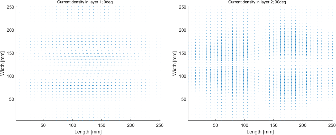
Current density plot for a
At last, the volumetric heat for an eight-layer quasi-isotropic laminate with
Effective heat for a quasi-isotropic laminate in the global axes system; 0°, 90°, 45°, −45° [top right to bottom left].
Effective heat for a quasi-isotropic laminate in the local material axes system; 0°, 90°, 45°, −45° [top right to bottom left].
ANSYS Maxwell simulations
The simulations reported in Fink et al.
5
were repeated and expanded to investigate the heating mechanisms in the thickness direction. The simulations performed using ANSYS Maxwell differed from the simulations done using WelDone in multiple, important, manners Two arrays of fibers with either The Maxwell simulations were done on the fiber level, micrometer level, not the laminate scale used in WelDone. In the Maxwell simulations the fibers were individually modeled and meshed. A layer was modeled as a set of parallel fibers, a single fiber array. In the Maxwell simulations the presence of a resin system was either deliberately omitted or added to investigate the effect of the presence of a resin system. In the Maxwell simulations the contact between fibers of different layers was deliberately modeled, or deliberately kept apart to investigate the effect of the fiber-to-fiber contact. To determine the solid loss the bounding box of fiber and resin was used in all calculations. The total volume was the same regardless the presence of resin or not.
With the points mentioned above in mind, the following investigation was performed; a
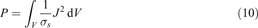
It is important to state that the variables in equation 10 have a different representation than earlier. P is the net magnitude of solid loss throughout the entire volumetric element, J represents the magnitude of eddy currents at each nodal point which in turn are a function of the magnetic field, and
The ANSYS Maxwell simulations were conducted on significantly smaller scale than the WelDone simulations: (i) to investigate which heating mechanism played a bigger role in heat generation in the thickness direction the individual fibers had to be modeled (presence of resin, or fiber-to-fiber contact between layers, or a combination of the two); and (ii) to keep the computational time acceptable, the number of fibers that could be modeled had to be minimized.
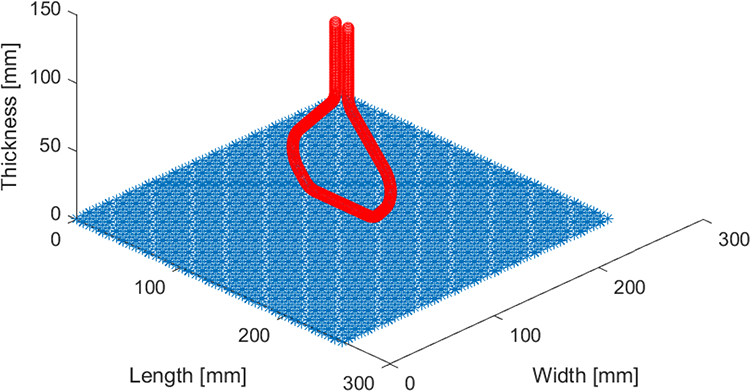
The model consisted of two arrays of carbon fibers are placed on top of one another (small gap) with a given orientation angle. The fibers are modeled as polyhedrons with 12 sides of diameter 7 µm and length 250 µm. A toroidal shaped coil made of copper is placed at 600 microns away from the center of the fiber intersection. Conduction cross sectional planes were created in the coil, which in turn acts as terminals for current flow. An excitation current of 500-Amps at 275-kHz was applied. The carbon fibers were attributed a bulk conductivity of 3000 Siemens/m. The conductivity value for the resin was negligible, however, ANSYS Maxwell requires a non-zero value entry, hence we used 1.0 Siemens/m. ANSYS Maxwell did not consider a material to be conductive unless its conductivity is greater than or equal to 1. The simulations were conducted with and without presence of resin, and the solid loss was investigated for a
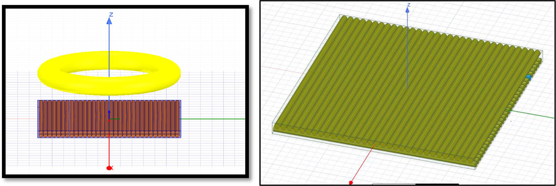
Representation of the ANSYS Maxwell model, (left)
It is important to state to investigate the heating mechanism on the fiber level the dimension of the “plate” and “coil” had to be reduced significantly. Otherwise, the number of elements required will to high for the software to solve the problem. In addition, if the coil was not reduced in size accordingly, then the heat generated due to coil size with respect to the plate size would make the investigation meaningless.
In addition, in the models used, the fibers in the layers were separated by a distance f of each other, and the layers were separated by c, see Figure 16. The distance f (7.7-
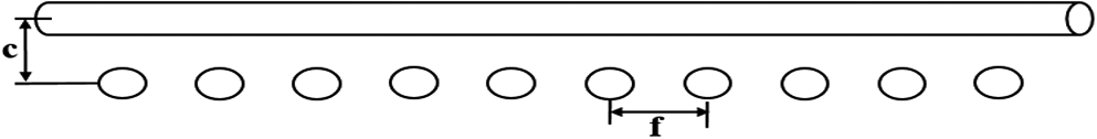
Two layers with 0’s and 90’s fiber orientation (front view).
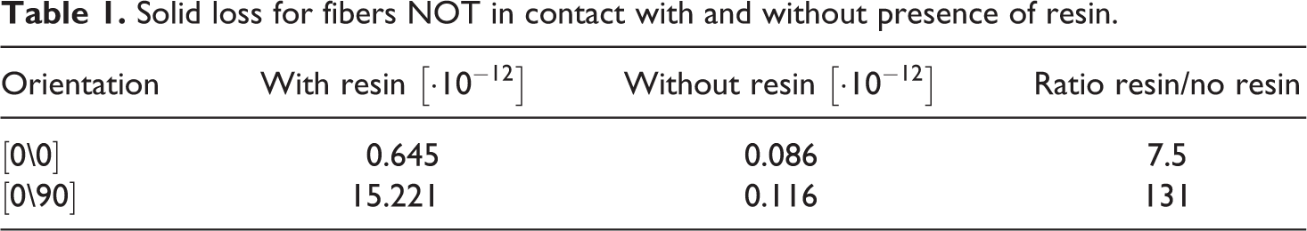
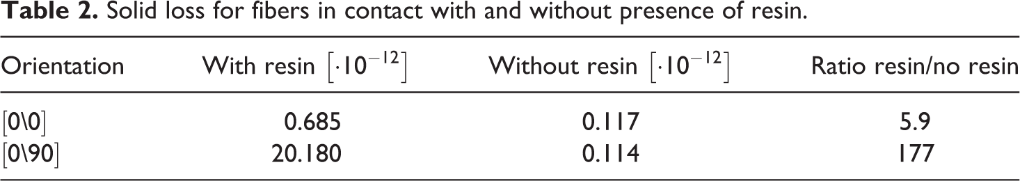
The results of the simulations, expressed as solid loss, are given in Tables 1 and 2 for the two laminate case (
Solid loss for fibers NOT in contact with and without presence of resin.
Solid loss for fibers in contact with and without presence of resin.
Conclusion
Using an in-house developed electromagnetic induction finite element package, WelDone, and the commercially available software package ANSYS Maxwell the heating mechanism involved with induction welding was investigated. Based on the results obtained from WelDone, it can be concluded that the heating in the fiber direction is most dominant when a laminate has multiple fiber orientations. If the all the layers of a laminate have the same orientation (e.g. all 0° or all 90° laminate), then the heating transverse to the fiber direction is most dominant. However, magnitude of heating is significantly larger for a laminate with orientation changes than one without. In addition, the results from the ANSYS Maxwell simulations showed that the presence of a resin has a larger contribution to the generated heat than fiber-to-fiber contact.
Therefore, Joule heating of fibers and Joule heating of polymer are the most dominant heating mechanisms in induction welding of thermoplastic composites. The contribution due to fiber-to-fiber contact resistance heating between layer are significantly lower, and therefore can be considered non-dominant.
Footnotes
Funding
The author(s) disclosed receipt of the following financial support for the research, authorship and/or publication of this article: The authors would like to acknowledge the ongoing support of the SmartStateTM Center for Multifunctional Materials and Structures (MFMS).