
Abstract
A novel recycling solution for thermoplastic composites (TPCs) was recently implemented. The processing steps comprise shredding of TPC offcuts to flakes of a few centimetres, melting and blending of the flakes in a low-shear mixer, extrusion of a molten mixed dough and subsequent compression moulding in a press. This material and process are similar to the compression moulding of long-fibre thermoplastics (LFTs) that have been in the market for decades, such as glass mat thermoplastics (GMT) or direct-LFT. However, the input material in this recycling route consists of multi-layered woven flakes, which is very different from the pellets or chopped rovings of other LFTs. Process- and material-induced heterogeneities such as fibre orientation, percolation, variation of fibre fraction, or fibre attrition may be different for this new material. The development of this recycling technology and future industrial applications require more confidence in the material and process. The objective of this study is to characterise these heterogeneities for this recycling solution, and compare them to those generated in regular LFTs. It was found that the process- and material-induced heterogeneities of the recycled TPCs are similar to other LFTs, for the aspects listed here: fibre orientation, percolation, variation of fibre fraction and fibre attrition. In comparison to GMT, the effect of the mixing step is particularly noticeable on the local variation of fibre fraction within the panels. Industrial applications of this recycling route will benefit from this similarity, as it improves the confidence in the material and process combination.
Keywords
Introduction
The use of continuous-fibre-reinforced thermoplastic composites (TPCs) has increased in the past decades in various industrial sectors, with a large focus in aerospace. 1 The ever-increasing TPC applications also leads to increasing amounts of production scrap, generated during various manufacturing steps. The combination of economic value of the TPC scrap and legislative incentives is pushing the industry to reuse or recycle this material more and more.2,3 As a consequence, several companies and research institutes involved in TPCs have developed recycling solutions specific to TPCs in recent years.4–12 In all of the implemented recycling routes, scrap material is first sorted and comminuted to the desired size, ranging from particles of a few millimetres to a few centimetres. The recycling solutions then proceed with a remanufacturing step that turns the composite particles into an end- or semi-product.
De Bruijn et al. 4 recently introduced a novel recycling solution involving shredding of scrap to produce flakes of a few centimetres, melting and blending of the flakes in a low-shear mixer, and extrusion of a dough that is directly transferred to a press for compression moulding (Figure 1). The low-shear mixing step was chosen for its ability to retain long fibres during mixing, while disentangling the flake structure. Additional polymer granules are added to the flakes in the mixing phase to lower the fibre fraction. Details on the mixing process used in this study are available in Vincent. 13
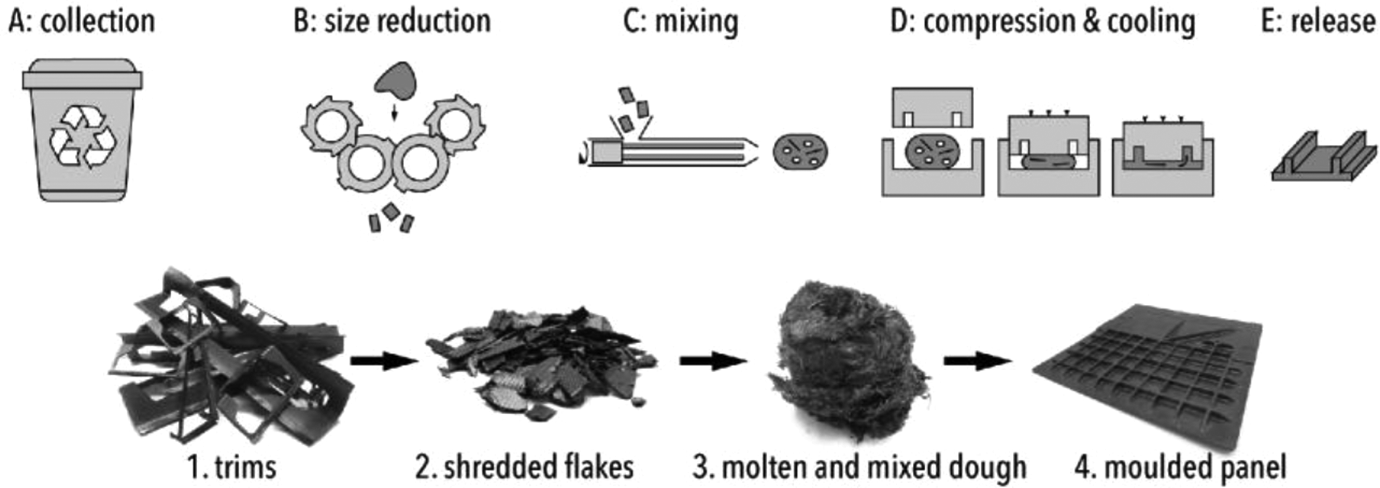
Schematic flow chart of the chosen recycling solution. The top row illustrates the various processing steps while the bottom row shows the material state between each step.
The mixing process provides the opportunity to process long fibres, known to exhibit high stiffness, strength and impact properties.14,15 After the extrusion, the molten dough, having a typical dimension of 200 × 150 × 150 mm, is a concentrated suspension of poly-dispersed bundles with a distribution of fibre length. The pressing phase is carried out in an isothermal mould, at a temperature lower than the polymer’s melting point, enabling fast pressing and a de-moulding step that only takes minutes. 16 The different doughs were all placed in the mould with a similar position and orientation.
The process and materials used by De Bruijn et al. are similar to the compression moulding of glass mat thermoplastics (GMT), carbon mat thermoplastics (CMT) or direct-long-fibre thermoplastics (DLFT), which have been developed over the past decades.17–20 In those processes, a molten material, which can be a dough or a stack of sheets, is placed in a mould with partial coverage, and subsequently pressed to flow the material into all of the intricate features of the cavity. The molten material described here is a highly concentrated suspension of fibres in a thermoplastic matrix at the moment of pressing, with the fibre length ranging from 3 mm to 100 mm. The fibres may be bundled together into clusters of various sizes. These highly concentrated fibre suspensions of long fibres (henceforth, long fibres are defined as those longer than 10 mm) feature some microstructural heterogeneities, which are inherent to this type of material and their evolution is often flow-induced. 21
From literature on LFT, several microstructural properties are known to be affected by the process, in turn affecting mechanical properties, and leading to heterogeneities in LFTs: Porosity and cracks: the compression moulding of LFTs does not completely eliminate all void pockets. These were mostly found in regions with limited consolidation pressure. On the one hand, this can occur on the edges of panels. On the other hand, jammed regions can lead to resin-rich regions that also lack pressure.
22
The location, percentage and type of porosity can affect the part performance. Cracks can occur during the cooling phase of the moulded part, due to the stress induced by the fibre bed and polymer shrinkage on the polymer. Fibre-matrix segregation and variations of fibre volume fraction (FVF): the flow of polymer and fibres of a concentrated suspension can lead to restriction of fibre movement, fibre bridging or jamming.20,23,24 This can contribute to a decrease in fibre fraction along the flow or in some intricate features such as ribs.
20
Besides, the material itself may have local variations of fibre fraction that do not average out during the flow phase.
19
Moreover, the mixing step studied in this article was found to result in uneven distribution of the fibres.
13
The pressing of these doughs may lead to variations in fibre fraction in the moulded component. Overall, the FVF is a major parameter influencing material properties. Its variation within a part does affect mechanical performance. Fibre length reduction, or attrition: several studies on LFTs confirmed that the compression moulding step can result in fibre damage and breakage.19,20,25,26 Although the mixing step in the recycling solution of De Bruijn et al. was chosen for its ability to limit fibre breakage, the forces in the moulding step may induce fibre damage that leads to fibre attrition. Decreases in fibre length is known to affect the mechanical properties.14,27 Fibre orientation distribution (FOD): during compression moulding of doughs, the flow of polymer and fibres is coupled. The fibres orient themselves due to interactions with the flow field and contact amongst themselves. In the case of highly concentrated suspensions with long fibres, the interactions between the fibres are accentuated. This is known to result in an FOD with systematic deviations compared to results of suspensions assumed to behave as single-phase flow, largely used for commercial numerical simulations.20,21 Fibre orientation has a major effect on the mechanical properties of fibre-reinforced composites. As such, its characterisation is crucial. Sink marks: the polymer crystallisation and cooling during the compression moulding phase leads to shrinkage. This can eventually create sink marks at thick regions or local thickness variations. This is known to occur in LFTs when large resin-rich regions exist.
5
Contrary to GMT, CMT or DLFT, the input material in the recycling solution of De Bruijn et al. consists of multi-layered woven flakes that disentangle in the mixing process. This may lead to differences in the type of heterogeneities as well as differences in their relation to the process conditions. Nonetheless, the development of industrial applications for this recycling solution is in progress, 16 and revealed a scattering in the mechanical properties. 4 The further development and use of this recycling solution requires improved confidence in the material-process combination, and therefore a better understanding of these microstructural heterogeneities. Hence, the objective of this article is to characterise the material heterogeneity and its link to the process. Comparisons to similar LFT processes and materials is included when relevant. This article focuses on the aspects listed above. Besides, this article will not look at the mechanical performance of the aforementioned recycled materials, which was the scope of a thesis by De Bruijn et al. 28 The reader may refer to it for more details.
The experimental characterisation of these properties will be studied using various methods: cross-sectional microscopy, C-scanning and X-ray radiography, density measurements, fibre attrition and orientation measurements. A description of the materials is presented first, and then the methods used in this study are described. A subsequent section will present the results before concluding the article.
Materials and process
Two materials were used for this study, carbon/polyphenylene sulphide (C/PPS) and glass/polypropylene (G/PP). C/PPS scrap material has been collected at various manufacturing sites and consists of the trimming edges of stamp-formed components. It was made of 3–4-millimetre thick laminated Cetex TC1100 5 harness satin (5HS) C/PPS at 50% FVF. The trims were shredded in-house using a two-shaft shredder, an S20 from Untha GmbH (Kuchl, Austria). The fibre length distribution (FLD) of the resulting shredded flakes was previously characterised 29 and is shown in Figure 2. It is characterised by a peak at 20 mm and a long tail for longer fibres. The C/PPS flakes (see Figure 3a) were then processed in a low-shear mixer with PPS granules added in to lower the FVF from the initial 50% to 35%, 26% or 19%. The material was mixed for 20 min at 10 rotations per minute (rpm) and moulded at 200 bar and 20 mm/s with a mould at 180°C, if not stated otherwise.
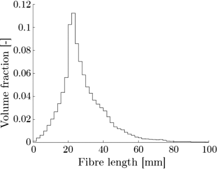
FLD of the shredded flakes used in this article, analysed in Vincent et al. 29
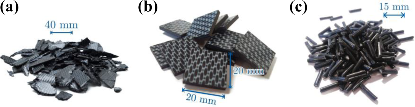
(a) Shredded C/PPS flakes, (b) square C/PPS flakes of 20 mm × 20 mm, (c) G/PP pellets of 15 mm.
Two types of panels were manufactured in this study: a flat panel and a ribbed panel both measuring 305 × 305 mm. The ribbed panel was designed to test the manufacturability of several geometrical features, following the guidelines in use for GMT.
18
The panel is shown in Figure 4 with a few highlights, and includes the following features (see also drawing in Supplemental material): An increase in thickness along the edges, to simulate component landing.
16
Such an increase is usually required for the assembly of LFT components using rivets. Ribs with various height-to-width ratios, from 2:1 to 4.5:1. Two quarters of the panel include various types of ribs to test the effect of the rib type at different flow distances on the filling behaviour. Various types of rib crossings: normal intersection, knockout at and coring at intersection.
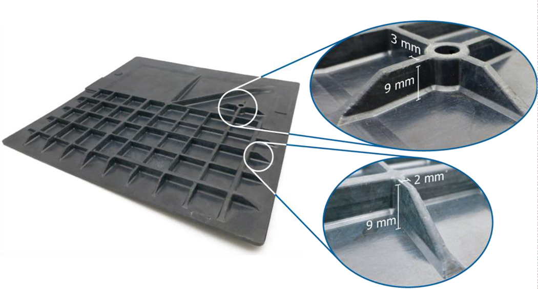
Photograph of a C/PPS ribbed panel. The two close-ups on the right show details on ribs and rib crossings.
The FLD measured on the flakes was assumed to remain the same during mixing because the deformation rates involved during this process are low. 13 Yet fibre attrition was expected in the moulding phase. From a statistical point of view, it is difficult to reliably measure the FLD after attrition when the input FLD is spread. Therefore, characterisation of the fibre attrition was performed with different flakes. Cross-ply 5HS C/PPS laminates were consolidated and then cut into squares of 20 × 20 mm (see Figure 3b). This way, the square flakes resemble the shredded flakes in terms of their laminated and woven structure, but the constant fibre length of the square flakes makes the measurement of fibre attrition statistically more reliable. These flakes were diluted to 20% FVF in the mixing step and then processed with the default settings.
Next to the C/PPS, several panels were moulded with readily available virgin LFT glass/PP (G/PP) pellets, with fibres of 15 mm, as shown in Figure 3c. The pellets were added at 40% and 60% fibre weight fraction, or approximately 19% and 35% FVF, respectively.
The G/PP panels were mixed for 15 min at 5 rpm, and moulded at 45 bar and 200 bar for the flat and ribbed panels respectively. The moulds were pre-heated to 80°C and were closed at 20 mm/s.
The different shape and structure of the input materials, consolidated woven carbon fibres and glass LFT pellets, clearly have an influence on the mixing process. Thus process parameters must be different to obtain a similar quality since mixing consolidated woven fibres feels and is a more difficult process. As a result of the tailored process parameters for both materials, the weave pattern of the carbon fibres is unseen and only loose fibres and fibre bundles can be found in mixed doughs.
Measurement methods
Visual inspection and cross-sectional microscopy
Visual inspection was first carried out on all panels to scrutinise the part quality. Surface defects such as improper filling or insufficiently mixed regions were searched for. Cross-sectional microscopy was extensively used on C/PPS at and ribbed panels. Cross-sections were cut at various locations, embedded, polished and inspected with an optical microscope.
Fibre orientation distribution and fibre attrition
The measurements of fibre attrition and FOD were performed on burnt-off specimens.
The FOD was characterised on one quarter panel of G/PP, as shown in Figure 5, which also highlights the location of the dough prior to pressing. The quarter panel was cut into nine pieces of approximately 50 × 50 mm. Each piece was placed in an oven at 550°C in an air environment for 3 hours in order to have complete matrix burn-off. The resulting fibrous structure was then placed under a camera mounted vertically. The fibre bundles were picked up with tweezers continuously while the camera took photographs of the fibre bed every 10 seconds. A square caul sheet was placed under the fibre bed and served as a reference to correct for geometrical distortion. A schematic of the set-up is visualised in Figure 6. The map of the fibre bundle locations and orientations was obtained from manual identification of each unique fibre bundle in the images recorded by the camera.
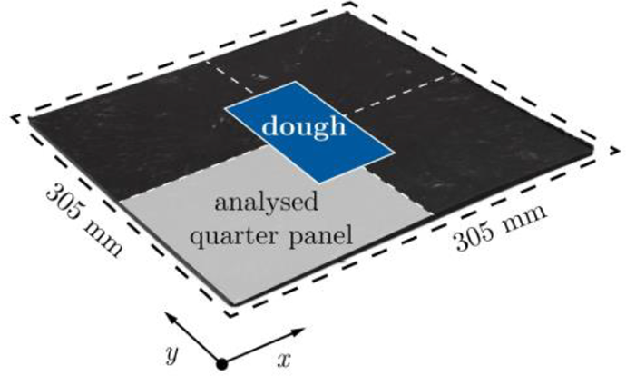
Photograph of a G/PP at panel, highlighting the locations of the dough prior to the moulding phase, and of the quarter panel analysed for the FOD measurements.
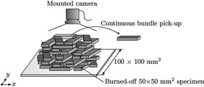
Schematic of a stack of fibre bundles framed by a caul sheet, showing the method used to record the locations of the bundles to measure the FOD.
The calculation of the local orientation tensors results in the FOD on the quarter panel. Approximately 2,000 bundles were picked up and identified in the process. It is possible to estimate the FOD in the panels with this method. Yet, the scatter in the dispersion of the fibre bundles during the mixing and moulding phase makes the identification of bundles complex and therefore makes very accurate measurements difficult.
The fibre attrition was measured for both a G/PP and a C/PPS panel. A flat panel was moulded for each of the two cases, from which a square specimen of four times the input fibre length in width was cut off (see Figure 7, left). The glass fibres all measured 15 mm in the input pellet, while the carbon fibres were all 20 mm long before mixing. As in the previous analysis, the square specimens were placed in an oven at 550°C until complete matrix burn-off. Burn-off of carbon fibre composites can be challenging as the fibres start degrading at these temperatures. Experimental tests were performed with the same material and fibres of known lengths prior to burning-off the C/PPS specimens in order to determine whether the procedure shortens the carbon fibres. No fibre length reduction was found with this burning-off method. As shown in the left diagram of Figure 7, the fibres located on the edges of the cut specimens may be cut, and must be removed from the analysis. Therefore, all fibres located in a border of one fibre length in width around the specimen were removed after matrix burn-off. The reclaimed fibres, in the centre square (Figure 7, right), were spread on a flat surface and photographed. The FLD of the reclaimed fibres was determined by manual identification of the fibres in the pictures.
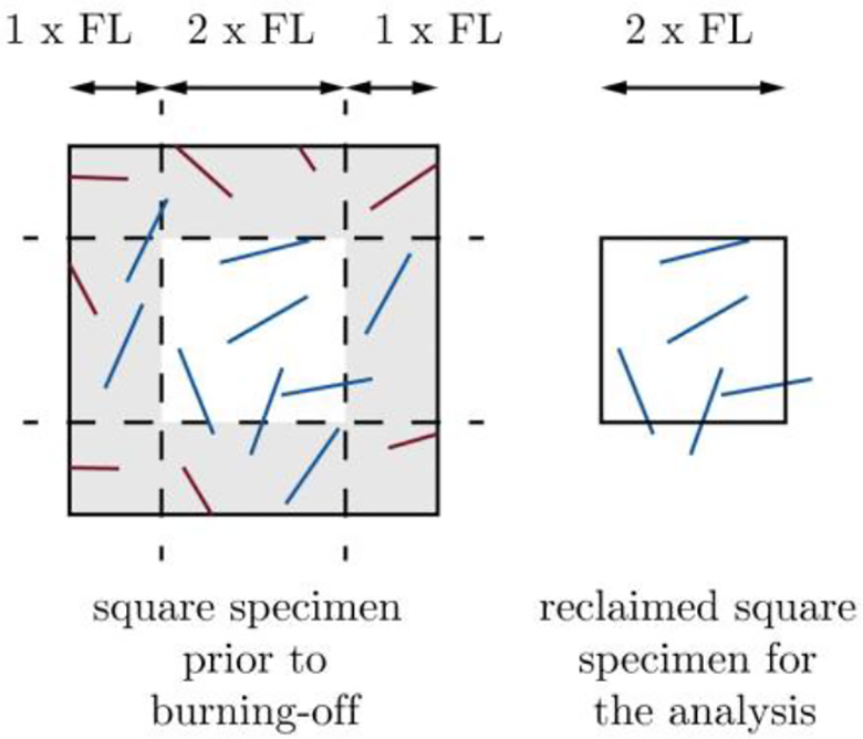
Schematic of the selection of fibres for the fibre attrition method. A square of four times the fibre length is cut from a panel. The matrix of this specimen is burnt-off in an oven. Fibres located in a perimeter of one fibre length in width may be cut, thus must be removed from the analysis. Therefore, only the central square of two fibre length is kept for the fibre length analysis.
Density measurements
The local variations in FVF of several C/PPS panels were determined via density measurements. For the ribbed panels, each rib and at section of several quarter panels was analysed (see Figure 8). The individual specimens weighed between 0.5 g and 1 g for the ribs, and around 1.5–2 g for the flat sections. Regarding the analysis of the FVFs for the flat panels, 32 pieces were cut from each half-panel, with each piece weighting between 4 g and 6 g. Each cut specimen was weighed while immersed in air and in ethanol at a measured temperature. The density and FVF of each specimen was then calculated according to Archimedes’ principle based on the two measurements assuming no porosity, following the operating guidelines with the Mettler Toledo balance used.
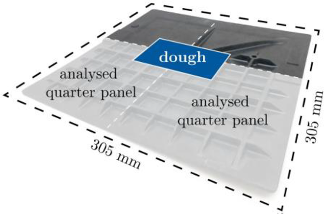
Photograph of a C/PPS ribbed panel, highlighting the locations of the quarter panels analysed for the density and FVF measurements.
C-scan inspection and X-ray photography
A few non-destructive inspection techniques were also investigated to determine whether they are applicable for such a material. Several C/PPS panels, flat and ribbed, were C-scanned by GKN Fokker (Papendrecht, the Netherlands). Additionally, several G/PP and C/PPS panels, both at and ribbed, were analysed via X-ray radiography by X-RIS (Liège, Belgium). The X-ray generator was set to a voltage ranging between 80 kV and 140 kV, and an amperage between 100 µA and 300 µA.
Results
Visual inspection
The C/PPS and G/PP ribbed panels were visually inspected to detect filling defects, resin-rich regions, regions of poorly mixed fibres and weld lines. The panels were visually homogeneous when looking at the patterns on the surface for both C/PPS and G/PP panels. However, some regions in a few C/PPS panels were whiter, presumably because of lower fibre content locally. These resin-rich regions form up to one cluster per panel and do not seem flow-dependent. On the contrary, they likely originate in the mixed doughs: a layer of molten polymer was sometimes detected on the piston during the extrusion of the doughs, which was then partially transferred to the rear of the doughs.
Complete filling of the ribbed panels was found to be successful for an FVF below 26% for C/PPS and up to 35% for G/PP. Similarly, the C/PPS doughs at 35% could not fill at panels completely. The cooling of the polymer during moulding increases the macroscopic viscosity, i.e. that of the dough, until the viscosity is too high to flow further with the available 200 bar pressure and 20 mm/s. The flow problems at high FVF are attributed to the increased number of fibre–fibre interactions in the high FVF doughs. Moulding G/PP was easier due to reduced fibre interactions compared to C/PPS, i.e. the average bundle aspect ratio is different. The C/PPS panels that were fully filled included some filling defects smaller than 1 mm3 in a few ribs, most likely resulting from the solidification and related shrinkage of the matrix during moulding. Weld lines were sometimes detected near a panel edge, for all types of panels: at or ribbed, G/PP or C/PPS.
Porosity and cracks
The presence of porosity was further inspected via cross-sectional microscopy images. The micrographs revealed nearly void-free sections in most locations of the examined C/PPS panels. Figure 9 shows a micrograph typical for this material with fibre bundles oriented in-plane close to the wall boundaries but with an out-of-plane component in thick regions. In these micrographs, clusters of void pockets were only observed at steep thickness increases and on the edges of the panels, as in the right-hand side of Figure 9.
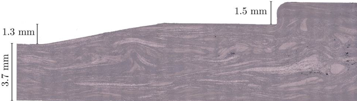
Cross-sectional micrograph of a thickness increase, taken on one of the C/PPS panel’s edge.
Figure 10 shows a cross-sectional microscopy highlighting the typical clusters of void pockets found in these locations. The size of these pockets ranges from 50 µm to 150 µm and their morphology is irregular. 30 The presence of void pockets in these regions may be the result of a decrease in pressure during cooling, which is expected for these regions. Similar results were also found by Wakeman et al. 31 during the moulding of GMT.
The presence of porosity was also investigated via C-scanning and X-ray radiography for C/PPS panels.
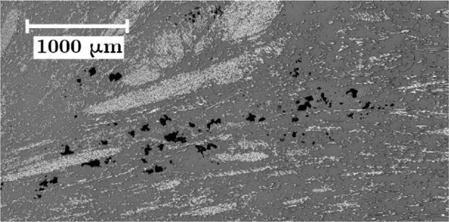
Cross-sectional micrograph highlighting a region with the typical void pockets found around the edges and at thickness increases.
The examination of the C-scans of the C/PPS panels was found to corroborate the limited fraction of porosity observed from cross-sectional micrographs. Conversely, X-ray radiography by absorption seems to hardly distinguish regions with porosity from regions with local variations of the material structure. Yet, high magnification X-ray photographs were able to spot cracks at weld lines, which can be seen in Figure 11, for instance, where a crack was observed due to the thermal shrinkage of the two sides of the line. Aside from the crack on the weld line, no other cracks, possibly originating from matrix shrinkage, were observed by microscopy, contrary to some findings of Rasheed 5 on the non-mixed compression moulding of C/PPS flakes at high FVF.
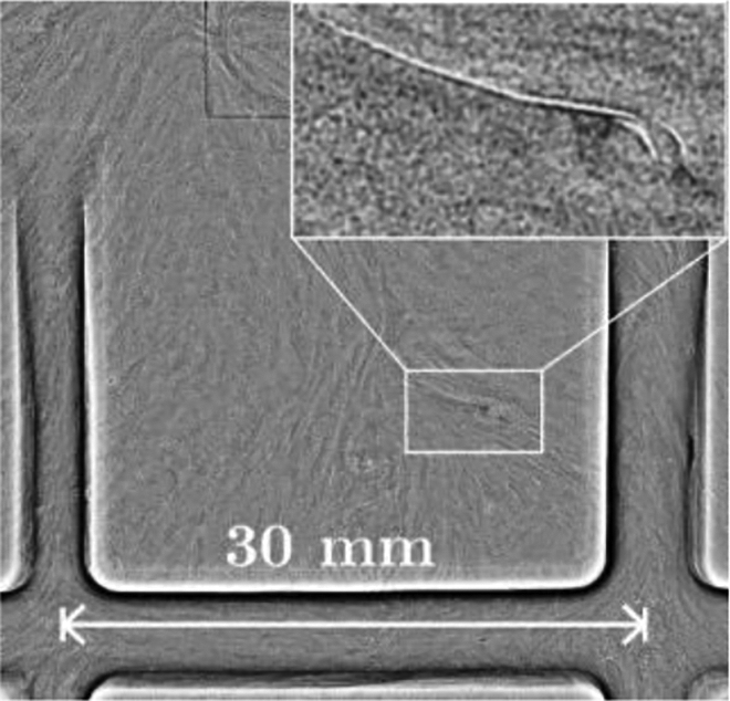
Close-up of an X-ray photography (positive mode) on a weld line. A small crack is visible at this weld line in white (top-right corner).
This very limited porosity fraction, while difficult to measure accurately, confirms the assumption of 0% porosity used for the density measurements, detailed in Section Materials and process.
Variations of fibre fraction and fibre-matrix separation
Density measurements were performed on four at C/PPS panels at various qualities of mixing. The local variations of FVF were obtained from the density measurements, assuming no porosity. The variations of FVF were also measured in the doughs manufactured with the same mixing settings and input flakes as in a previous study by Vincent. 13 Table 1 summarises the results and qualitatively classifies the mixing quality of the panels and doughs as poor or good, based on the findings of Vincent. 13 The results reveal a correlation between the standard deviations of the doughs and panels: improving the quality of mixing of the doughs increases the homogeneity of the panels. The difference between the standard deviations of doughs and panels may be due to the different measurement methods and sample sizes.
Summary of measurements of the variations of FVF for C/PPS at panels and doughs.
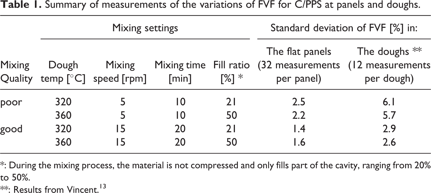
*: During the mixing process, the material is not compressed and only fills part of the cavity, ranging from 20% to 50%.
**: Results from Vincent. 13
For all four panels, the variations in FVF were found to be grouped in large clusters, with a few clusters of higher and lower FVF per panel. However, no reduction in FVF was observed along the flow length, indicating an absence of flow-induced percolation for this material. As a consequence, it is suggested that the variations of FVF in the flat panels are only a result of the mixing technology, or the random distribution of fibres as in GMT and CMT. 19 The low-shear mixing technology was chosen for its ability to not break fibres, with the drawback of a limited shear rate and mixing efficiency in comparison to screw extruders.
Density measurements were also performed on C/PPS ribbed panels at nominal FVFs of 26%. The local FVF was determined for all flat and all rib sections in the selected panels based on the Archimedes principle. Figure 12 shows the results for quarter panels, where all coloured cells represent a measurement of FVF, for either a rib or a flat section, and where the dough flowed from the centre of the panels towards the edges (Figure 12a). Errors in weight measurements in air and ethanol were found to account for variations up to 1% of FVF. Table 2 summarises some statistics for these three quarter panels.
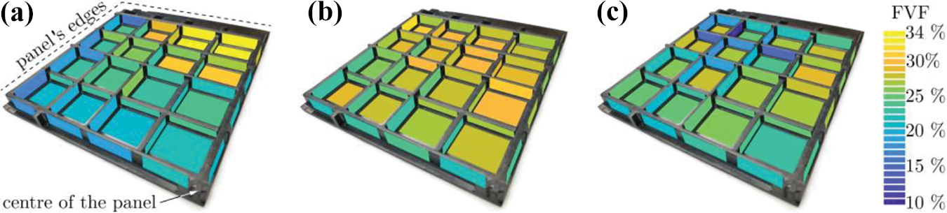
Measurements of the FVFs in all ribbed and flat sections for three C/PPS quarter panels. The quarter panels (b) and (c) belong to the same ribbed panel (bottom-right and bottom-left quarters from Figure 8 respectively), while (a) is from a different panel. For all quarter panels, the centre of the panel is located at the bottom-right position. The selected panels are not especially well-mixed, in order to study the limits of the material and process, but were both processed with the same settings.
Several statistics calculated from the distribution of FVFs of the quarter panels in Figure 12.
It was found that the variations of FVF are grouped in clusters and not affected by the flow, similar to the results of the flat panels. For instance, Figures 12a and 12c show regions with high and low FVF respectively in two corners instead of a decrease from the centre to the edges. Most notably, the region of low FVF in Figure 12c is located exactly on the region with a resin layer on the surface, mentioned earlier. This confirms that whiter regions, i.e. with higher resin content on the surface, have a low through-thickness FVF on average. The ribs were found to have a reduction of FVF of 2% 4% on average compared to their surrounding at sections, independently from the rib height-to-width ratio. Still, a few ribs were found to have an FVF higher than the flat sections around them.
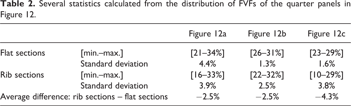
Fibre-matrix separation was not found to be more severe for tall or thin ribs. Similarly, no difference was found between ribs parallel and perpendicular to the flow direction. The reduction in FVF in ribs has been studied in details for GMT,20,23,24 both experimentally and numerically and this reduction was also found to occur in multiple situations: ribs parallel or perpendicular to the flow direction, and ribs located close or far from the initial position of the dough. Kuhn 20 analysed the causes for the fibre-matrix segregation phenomenon in the ribs. They observed bundle locking at multiple locations in the ribs via X-ray tomography. However, it is unclear whether Kuhn used stitched or non-stitched GMT, which can alter the interpretation of the results. Similar bundle locking was observed by Wakeman et al. 31 in flat regions along the flow length. Such phenomena were also observed in the ribbed panels made from C/PPS and G/PP in this study. Figure 13 presents a cross-sectional micrograph highlighting this locking in a C/PPS rib. The bundle that is circled in Figure 13 is perpendicular to the cut plane, while the bundle following the curve is mostly in plane.
(a) Shows a cross-sectional micrograph in a C/PPS rib, focusing on two bundles being locked. The distinction between the two bundles is determined by their orientation and is highlighted with the solid and dashed lines. (b) Shows the location of the locked bundles in the rib.
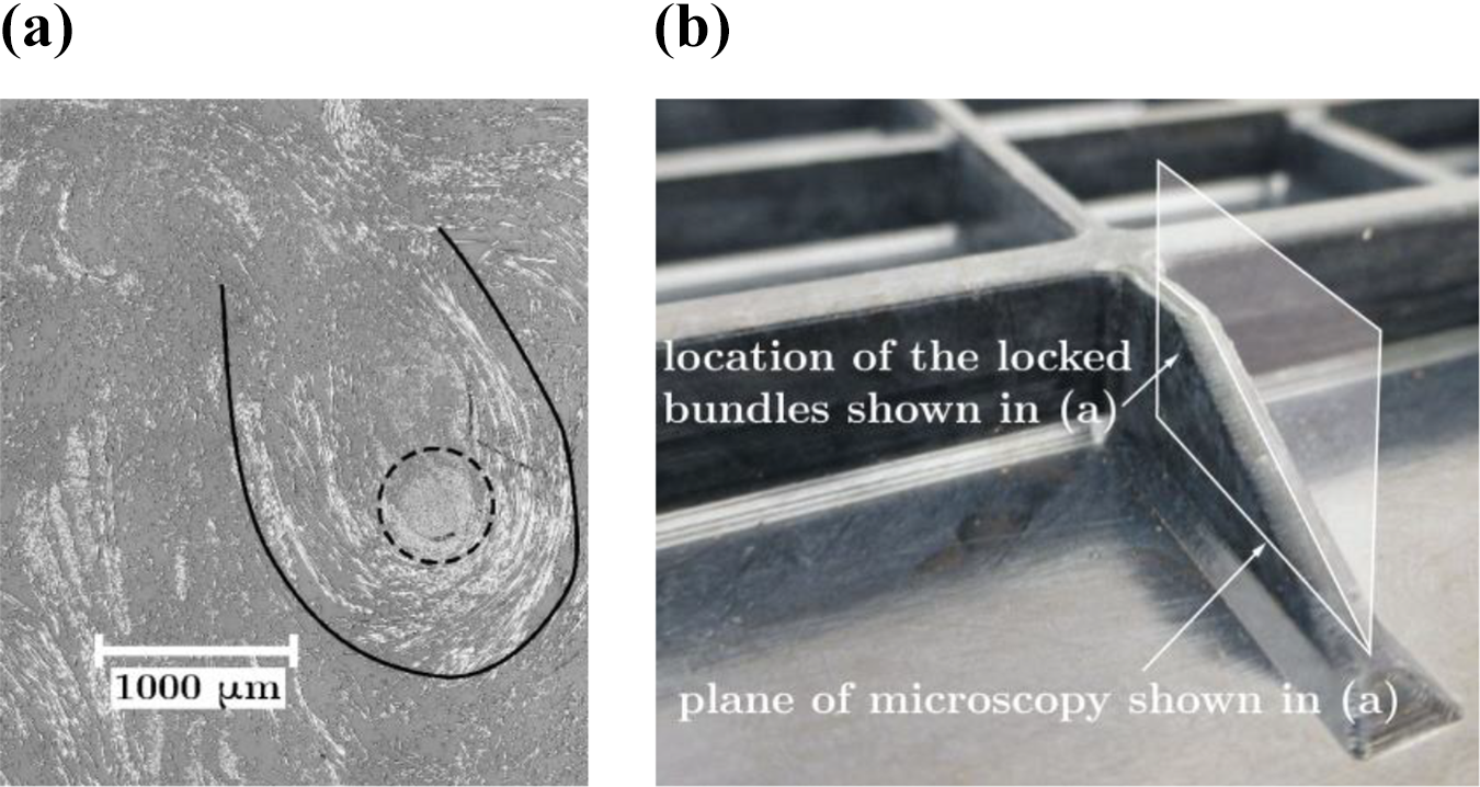
Figure 14 shows an X-ray photograph of a G/PP ribbed panel where several locked bundles were observed close to the edges of the panel.
Top view X-ray photograph of a G/PP ribbed panel highlighting bundle locking (white arrows).
Fibre attrition
Carbon and glass fibre bundles were assumed to not break during the mixing phase, which was selected for its low-shear forces. The moulding phase, on the contrary, can result in fibre attrition, as observed in a previous study. 32 Fibre attrition of G/PP and C/PPS was measured following the method described in Section Measurement methods. The glass fibres after burn-off were found not to be reduced in length. On the other hand, the length of the carbon fibres was reduced as shown in Figure 15. About 50% of the fibre bundles remained at 20 mm, their original length, while the rest were reduced to lengths varying from 2 mm to 20 mm. The difference in fibre attrition between G/PP and C/PPS can be attributed to multiple factors: the different matrix viscosity under the processing conditions, and the bundle aspect ratios. Contrary to the findings of Caba et al. 32 for a C/PP mat, the percentage of short fibres, i.e. smaller than 1 mm, is very limited. It is yet unclear why such a discrepancy exists between the results of G/PP and C/PPS on the one hand, and C/PP on the other hand, considering that the moulding conditions in all cases are very similar.
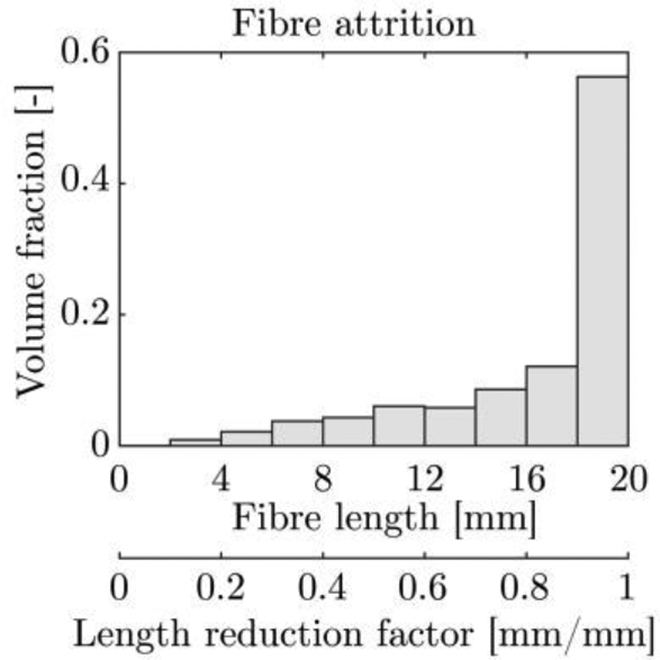
FLD after moulding of a C/PPS dough, highlighting the fibre attrition happening during the moulding of a C/PPS dough. All fibres measured 20 mm before the mixing and moulding phase.
Estimate of the fibre length reduction in the moulding phase for an input FLD measured in shredded C/PPS flakes. The fibre length reduction factor in Figure 15 is used for the calculation.
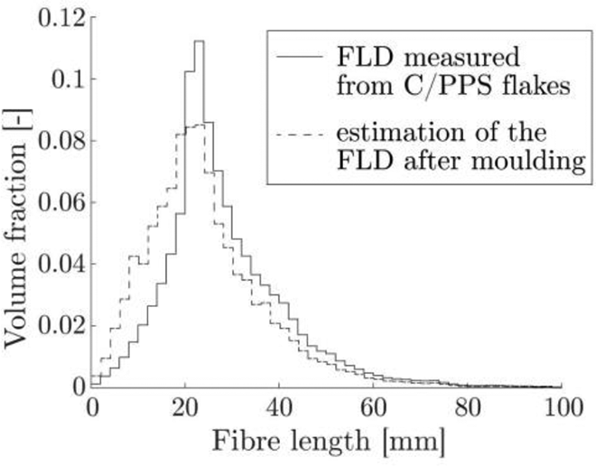
The findings on fibre attrition in the moulding phase are substantial for micro-modelling of the mechanical properties of the panels. 4 For the current purposes, however, the experimental measurements were performed using flakes of a constant fibre length of 20 mm. In order to extend these results to the case of shredded flakes, experimental measurements could be performed for these flakes. However, the FLD of these flakes is broad, ranging from 2 mm to 80 mm, and subject to variation. Accurate measurement of the fibre length reduction is hardly possible in this case, because a large number of experiments would be required to obtain a statistically reliable measure of the attrited FLD. Instead, an estimated fibre length reduction in the case of shredded flakes was calculated. The FLD prior to processing was measured from the flakes 29 and is shown in Figure 16 as a solid line. Based on that, each fibre length was assumed to be attrited similarly to the measured 20 mm long fibres (Figure 15), i.e. each fibre length experiences the same ‘length reduction factor’, shown in the second X-axis of Figure 15. The estimated reduced FLDs were calculated for all fibre lengths of the solid line distribution (Figure 16), and then combined to form the dashed FLD in the same figure. There is a visible, but small, reduction of the fibre lengths, which could result in a very limited impact on the overall mechanical performance of the material. This estimation may be conservative, as longer fibres tend to break more, and fibres shorter than 10 mm tend to break less, leading to a narrower distribution. The effect on mechanical performance is expected to be limited as bundles with fibres longer than the average of about 20 mm, which are more prone to break, exceed the critical bundle length.
Fibre orientation
The fibre orientation of moulded panels was characterised in-plane for a quarter G/PP at panel using the method described in Section Measurement methods. The out-of-plane component of the fibre bundles was inspected via cross-sectional microscopy for the C/PPS ribbed panels. It is clear that the G/PP pellets and C/PPS flakes have different mesostructures, which leads to differences in fibre-fibre interactions and FODs in the doughs. Even so, the C/PPS flake structure loosens well in the mixing process, leading to entangled bundles similar to the microstructure in G/PP doughs. The characterisation of the in-plane FOD for the case of G/PP provides indications regarding the FOD of panels moulded with this recycling solution.
Figure 17 shows the results of the G/PP quarter panel after burn-off. The identified fibre bundles from image analysis are displayed on the left side. The dough was placed in the centre of the panel, which is shown in the upper right corner of the images, and then flowed towards the edges. Figure 5 in the previous section illustrates the location of the analysed quarter panel. The right side shows a representation of the FOD using the local second-order orientation tensors that were computed from the distribution of bundle orientations and locations. The ellipses’ axes and orientations translate into the diagonal terms of the diagonalised second-order orientation tensors and the direction of its eigenvectors respectively.20,33
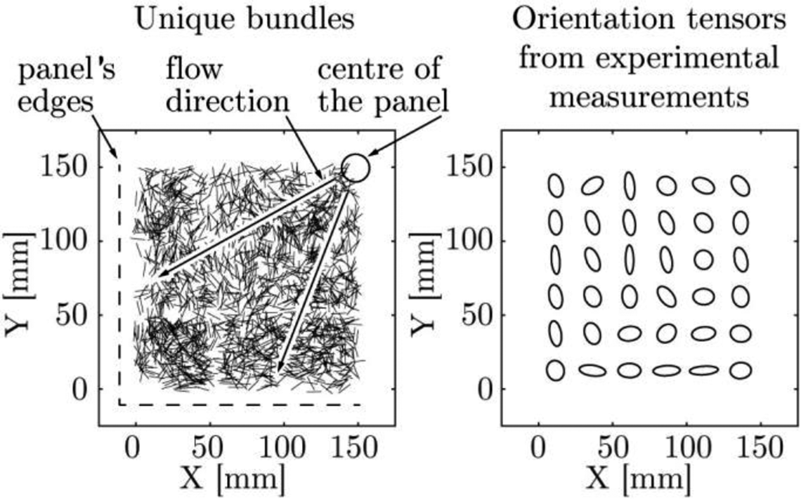
Location and orientation of the identified bundles from a quarter G/PP panel (on the left) and its the local FOD represented by orientation tensors (on the right).
The ellipse’s orientations and eccentricities show that most fibres are oriented perpendicular to the flow direction. This result was expected from previous work on the rheology of SFT and LFT,20,21 from Jeffery’s equation,34,35 and considering the moulding conditions in this study: a no-slip condition on the (cold) walls of the mould is assumed and the material exhibits fountain-flow behaviour. Notably, the ellipses in Figure 17 present large local variations of fibre orientation. These originate from the bundle interactions, and when bundles orient themselves in the flow, this creates local jamming, which is highly dependent on the initial conditions.
Most modelling approaches to compute fibre orientation treat the fibre suspensions as a single-phase fluid, with the fibre orientation taken into account with models derived from the Folgar-Tucker equation.21,35 The flow of highly concentrated long-fibre suspensions was proven to deviate from these single-phase flows, 21 which was also found in GMT.20,21
A comparison between the FOD calculated with these single-phase models and the FOD measured experimentally was made, to determine the extent of the deviation. Regarding the single-phase flow, a numerical simulation of the compression moulding of a molten LFT dough was performed using MoldFlow using material properties very similar to the experimentally used G/PP LFT pellets. The calculation of the fibre orientation in MoldFlow is based on developments of the Folgar-Tucker equation,35,36 which includes a diffusion coefficient that takes into account the interactions between fibres during the flow to a varying level of accuracy. The material for this simulation was G/PP LFT pellets with a set length of 10 mm, and an initial in-plane 2D random FOD. The orientation tensors of the bottom-left quarter panel at the last time step were exported and are shown in Figure 18. Similar to the experimental measurements, the fibres orient themselves mainly perpendicular to the flow direction in the MoldFlow simulation. As expected, the single-phase flow results in a homogeneous FOD, which does not present any local variation. Simulations of LFTs using single-phase flow, especially for the present recycling solution, can still provide an estimate of the FOD of moulded components. In turn, they can help predicting mechanical performance or warpage in the moulded panels.
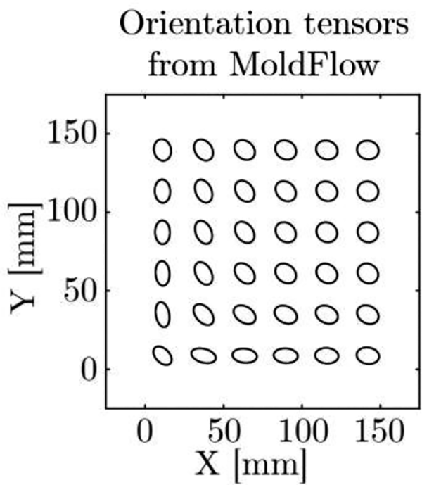
Fibre orientation tensors exported from MoldFlow for a simulation of compression moulding of a G/PP dough.
Apart from the in-plane FOD of moulded panels, fibre orientations may have an out-of-plane component. A strong out-of-plane component definitely leads to variations in mechanical performance compared to a solely in-plane FOD. Therefore, the out-of-plane component of the moulded at and ribbed panels was investigated, from cross-sectional micrographs. It was found that all at regions have primarily in-plane fibre orientation as long as the thickness does not exceed 3.5 mm. Otherwise, the FOD contains a large out-of-plane component in the core regions, as in Figure 9. This phenomenon also appears for thick ribs, compared to thin ribs, with their core regions containing bundles that are not parallel to the mould walls. The orientation of the ribs, perpendicular or parallel to the flow direction, was found to barely influence this phenomenon.
Conclusion
A novel recycling solution for TPCs, recently introduced by De Bruijn et al. 4 consists of the following steps: shredding, low-shear mixing and compression moulding. This recycling solution shares similarities with the compression moulding of GMT, CMT or DLFT, both in terms of processing and material properties. However, several features make this material-and-process combination specific for this approach, with the input material, consisting of multi-layered woven flakes of a few centimetres combined with the low-shear mixing step, minimising fibre fracture but having possible limited mixing efficiency. 13
Such highly concentrated LFT suspensions have inherent heterogeneities induced by the process or by their stochastic structure, which are known to affect the mechanical properties of moulded components. These heterogeneities include, not exhaustively, fibre orientation, fibre attrition, fibre-matrix separation, variations of fibre fraction, and fibre microstructure.
Previous research work has characterised such heterogeneities for GMT, CMT and DLFT. The objective of the current study was to determine whether the new recycling solution and TPC scrap have such heterogeneities for C/PPS and G/PP, and if so, to compare them to the already existing LFTs described above.
The results showed that the heterogeneities in the recycled TPCs are similar to those in other LFTs: Little to no porosity was observed in compression-moulded C/PPS and G/PP panels from quality inspection. Cracks may exist at weld lines, but should be prevented, as detailed in GMT guidelines. Some variations of FVF within the moulded flat and ribbed panels seem to originate from the input mixed dough. Large improvements of the quality of mixings seem to be possible and are expected to lead to reduced variations of FVF.
13
Flow-induced fibre-matrix separation was limited and only observed in intricate features such as ribs, but not along the flow length, which is in accordance with results on GMT.
20
Fibre attrition during the moulding phase only occurred for C/PPS, at a limited extent compared to former findings on CMT.
32
The fibre orientation was found to deviate from the FOD results of single-phase flow simulations, as expected from such a material. Yet, the fibres mostly orient perpendicularly to the flow direction. These results are completely in agreement with general findings on the FOD in highly concentrated suspensions of long fibres.
21
The out-of-plane component of the fibre orientations was also investigated and found to be limited for sections thinner than 3.5 mm.
The similarity between the recycled TPCs and GMT or CMT is positive with respect to the understanding of this material. It improves confidence in this novel recycling solution and helps the further development of industrial applications.
Regarding the studied non-destructive inspection, several conclusions can be drawn. C-scans of C/PPS panels were successful in detecting material homogeneity in terms of porosity, yet limited conclusions can be made with this technique when it comes to small cracks, fibre orientation, fibre fraction or weld lines. X-ray radiography was better capable of detecting fibre orientation (for G/PP) and weld lines (for C/PPS). The measurement of fibre orientations from the radiographs seems challenging, and proper crack detection requires multiple, possibly laborious, radiographs. Moreover, porosities are much harder or even impossible to detect with X-ray. Other potential inspection techniques could be thermography or CT-scanning, but these have not yet been investigated in this project.
Supplemental material
Supplementary_Figure_and_Table - Process- and material-induced heterogeneities in recycled thermoplastic composites
Supplementary_Figure_and_Table for Process- and material-induced heterogeneities in recycled thermoplastic composites by Guillaume A Vincent, Thomas A de Bruijn, Sebastiaan Wijskamp, Martin van Drongelen and Remko Akkerman in Journal of Thermoplastic Composite Materials
Footnotes
Acknowledgements
The authors are grateful to the project partners: Toray Advanced Composites, GKN Fokker, Cato Composite Innovations, Dutch Thermoplastic Components and Nido Recycling Techniek. The authors are also thankful to X-RIS (Liège, Belgium) and GKN Fokker for performing X-ray photography and C-scans respectively.
Funding
The author(s) disclosed receipt of the following financial support for the research, authorship, and/or publication of this article: This project was financed by the Dutch Organisation of Applied Research – SIA, through the project grant SIA-RAAK 2014-01-72PRO.
Supplemental material
Supplemental material for this article is available online.
References
Supplementary Material
Please find the following supplemental material available below.
For Open Access articles published under a Creative Commons License, all supplemental material carries the same license as the article it is associated with.
For non-Open Access articles published, all supplemental material carries a non-exclusive license, and permission requests for re-use of supplemental material or any part of supplemental material shall be sent directly to the copyright owner as specified in the copyright notice associated with the article.