
Abstract
Continuous fiber-reinforced thermoplastic (c-FRTP) has received attention for reducing automobile weight. Hollow molded parts made by pultrusion molding of braided composites may improve the performance and reduce the weight of automotive parts. However, pultrusion molding of braided composites suffers from productivity problems. This research aimed to increase the productivity of pultrusion molding of braided fabrics to facilitate its practical application. The effects of the fiber intermediate fabrication method and the resin melt viscosity on the impregnation and mechanical properties of the composite were investigated. Glass fiber and polyamide 66 (PA66) were used as the fiber intermediates. Two types of fiber intermediates were used, one with interlace processing and one with the fibers lined up. PA66 fibers with high and low viscosity were used. A correlation was found between impregnation properties and mechanical properties of the molded products, which improved as the unimpregnated ratio decreased. Detailed observations revealed that impregnation of PA66 resin into glass fiber bundles started from interlaced points in the fiber intermediates introduced by interlace processing. Furthermore, low-viscosity PA66 resin had higher fluidity, which better promoted impregnation into glass fiber bundles. These results clarify design guidelines for fiber intermediates to realize better mechanical properties and shorter molding cycles.
Keywords
Introduction
Recently, there has been growing demand to reduce the weight of automobiles in order to improve fuel efficiency and lower CO2 emissions. To date, automobile weight has been reduced by using resin materials for various components and interior fittings. These resin materials are single thermoplastic resins or fiber-reinforced plastic (FRP) composites, in which resin is reinforced with glass fiber or carbon fiber, each of which has high elasticity and high strength. FRP composites are fabricated by injection molding and have a low proportion of short reinforcing fibers. Compared with other types of FRP, those used in automotive applications exhibit mechanical properties that are relatively close to that of resin. As of 2001, FRP accounted for about 35% of automobile bodies by volume. To achieve even lighter automobiles in the future, it may be necessary to reduce the weight of not only design parts, such as interior and exterior fittings where resin materials are already used, but also primary structural components that constantly bear large loads and where metal materials are mainly used. For example, triangle joints, seat parts, door modules, bumpers, and crash boxes. Therefore, there is demand for high-performance lightweight materials, and one candidate is FRP reinforced with a high content of continuous resin material fibers. Such high-performance FRP has been used in a limited number of fields, such as aircraft, sporting goods, and construction. 1 However, this kind of FRP needs a long molding time because its matrix resin is a thermosetting resin that must undergo a chemical reaction to cure during molding and is also labor intensive. These drawbacks mean it is considered unsuitable for automotive application in terms of productivity and cost. In recent years, continuous fiber-reinforced thermoplastic (c-FRTP) composites have attracted attention. Their matrix resin is a thermoplastic resin that does not require a chemical curing reaction, similar to thermosetting resins, which enables automated production and increased productivity.2–8
There are several problems with turning c-FRTP into products. Using thermoplastic resin as the matrix resin necessitates heating and melting the resin and having it penetrate the reinforcing fiber bundles during molding of the composite materials. However, the melting point of thermoplastic resins is extremely high compared with that of thermosetting resins, and a long time may be required to completely penetrate the inside of the fiber bundles, which would lower productivity. To resolve this problem, a fiber intermediate material for c-FRTP molding is required. The fiber intermediate material is a molding material that shortens the impregnation time by including the resin in the reinforcing fiber bundle to shorten the distance between the reinforcing fiber and the resin. In other words, shortening the impregnation distance shortens the impregnation time, allowing composite materials with higher impregnation to be molded in a short time. 9 There are many different types of fiber intermediate materials with different forms. Examples include those with a mixture of fiber resins and reinforcing fibers, those in which powder resin is arranged inside the reinforcing fiber resins, and those in which resin penetrates open reinforcing fibers. Using these fiber intermediate materials enables impregnation to reach completion in a short amount of time.
Various studies have investigated the molding and mechanical properties of c-FRTP using composite fiber yarn. Demircan et al. performed experiments, such as tensile testing and three-point bending testing, on molded parts of materials with different biaxial weft-knitted loop lengths (8.0, 9.2, 10.5, 11.9, and 13.5 mm) and different knit structures (plain, interlock, tuck, and tuck and miss) to understand the mechanical properties of biaxial weft-knitted composite fibers. They used fiber intermediate materials composed of polypropylene and polyamide as the matrix resin fiber and composite yarns using glass fiber and aramid fiber as the reinforcing fiber. The best mechanical properties were obtained when using a knit loop length of 8.0 mm and an interlock knit structure.10,11 Kim et al. investigated the relationship between the molding conditions and impregnability in the filament winding process. Using composite yarn as the fiber intermediate material, they found that the impregnability improves when the nozzle outlet temperature is high and the composite yarn feed speed is low. 12 Wakeman et al. investigated the molding conditions for compression molding of composite materials from fabrics with few voids and excellent mechanical properties by using composite yarns of glass fiber and polypropylene fiber, and found the optimal molding conditions. 13 Choi et al. investigated the fabrication conditions for fiber intermediate materials by applying the method of manufacturing composite fiber of carbon fiber and PEEK fiber using air, and they revealed the relationship between the manufacturing conditions and mechanical properties, as well as the underlying mechanisms. 14
However, no studies have investigated the productivity of fiber intermediate materials, which affects the final manufacturing cost, or resin viscosity, which is expected to affect impregnability. This research therefore investigated composite yarn fabrication methods and matrix resins that can be impregnated at high speed with the aim of creating fiber intermediate materials with high impregnability and productivity. We focused on the interlace (I/L) process, which can create composite fibers by mixing both matrix resin fibers and reinforcing fibers using air at high speed. Then, using fiber intermediate materials fabricated by this process, we manufactured unidirectional reinforced composite material by a heated compression molding technique. We investigated the effect of the presence or absence of the I/L process on the impregnability and mechanical properties, as well as the effect of resin viscosity on the impregnability. We also examined the applicability to both preform manufacturing and pultrusion using braiding technology and fiber intermediate materials, considering hollow parts such as pipe shapes that are used in the primary structural parts of automobiles. We evaluated the impregnation state by cross-sectional observation and investigated the mechanical properties by bending tests.
Experimental
Materials
Four fiber intermediate materials were fabricated with E glass fiber (686dtex/400f, Nippon Electric Glass) as the reinforcing fiber and PA66 fibers with high (470dtex/136f, Leona Asahi-Kasei) and low molecular mass (56dtex/96f, Leona Asahi-Kasei) as the matrix resin material (Table 1). The volume ratio of glass fiber to resin fiber was 39.5:60.5 in each intermediate material.
Experimental specimens.
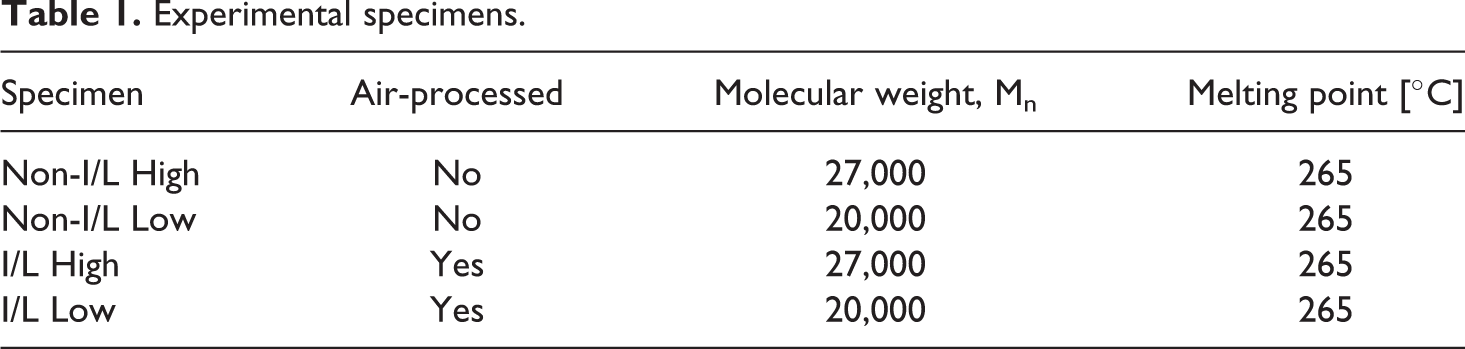
Interlacing is a fiber processing method that periodically interlaces fibers by blowing aligned fiber bundles with compressed air from the side (Figure 1). Figure 2 shows a photograph of the interlaced yarn. The interlaced yarn alternates between interlaced points and non-interlaced regions. The fibers are interlaced where the width of the fiber bundle narrows. The regions that are not interlaced form yarn where the glass fiber bundle and the resin fiber bundle are aligned parallel to each other. The specimens of intermediate material that were interlaced are named I/L and the non-interlaced intermediate material with the parallel yarn is named Non-I/L. Because the PA66 resin matrix material has a high melting viscosity when the molecular mass is large and a low melting viscosity when the molecular mass is small, the samples containing these resins are named High and Low, respectively. Compression molding was performed in the unidirectional specimens I/L High, I/L Low, Non-I/L High, and Non-I/L Low. Non-I/L yarns could not be produced in large quantities because they were difficult to handle without I/L due to fluffing during winding after interlacing because of their low molecular weight and softness. Therefore, braided pultrusion molding, which requires a large amount of material for molding, was evaluated in the I/L High, I/L Low, and Non-I/L High samples.
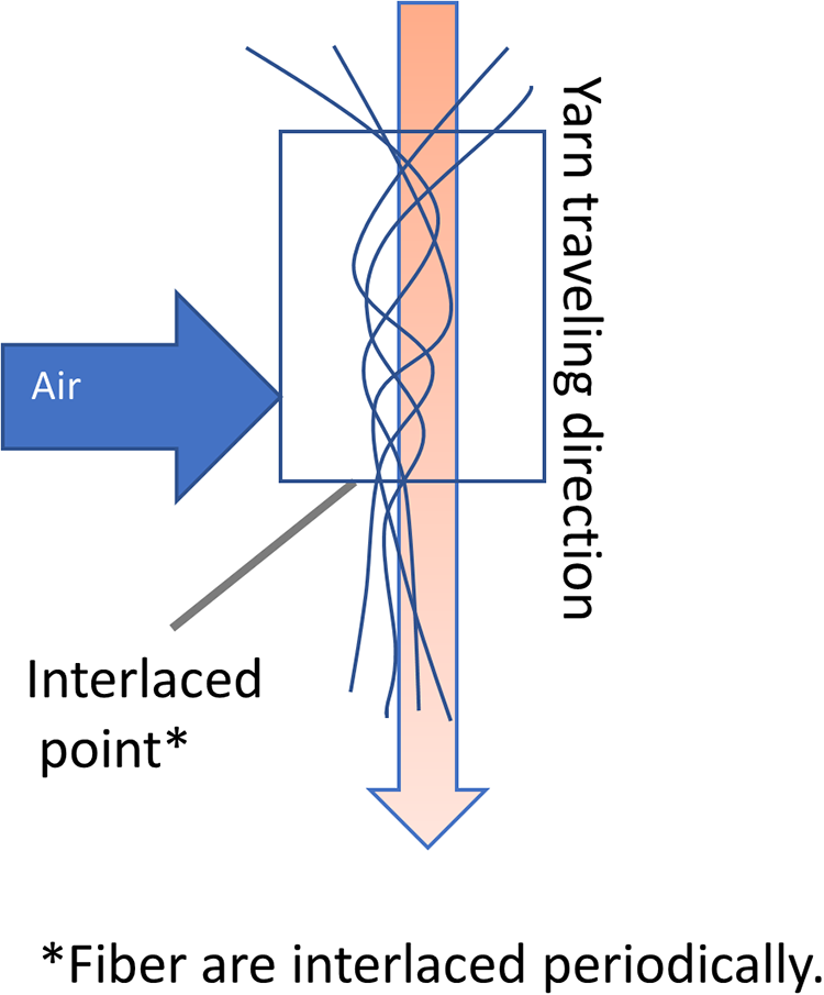
Schematic of interlacing process.
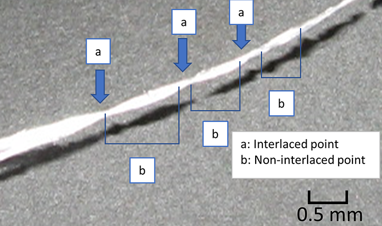
Interlaced points and non-interlaced parts of mixed fiber yarn.
Molding method
Unidirectional material compression test molding method
We describe the fabrication of the unidirectional material used in the experiments. Figure 3 shows a schematic of the fabrication method. For test specimens 200 mm long, 20 mm wide, and 1 mm thick, the interlaced yarn was first wound onto a metal frame to give a width of 20 mm. The wound yarn was placed in a die heated to a molding temperature of 285°C, and then immediately returned to the hot-press molding machine (Satoh Iron Works Co., Ltd.) and pressed at 3 MPa. The sample was allowed to cool under pressure. The time from when the pressure was applied until cooling began was defined as the molding time, and was set to 60 s.
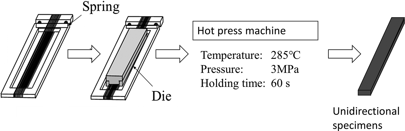
Molding process flow.
Braided composite material cylindrical pultrusion molding
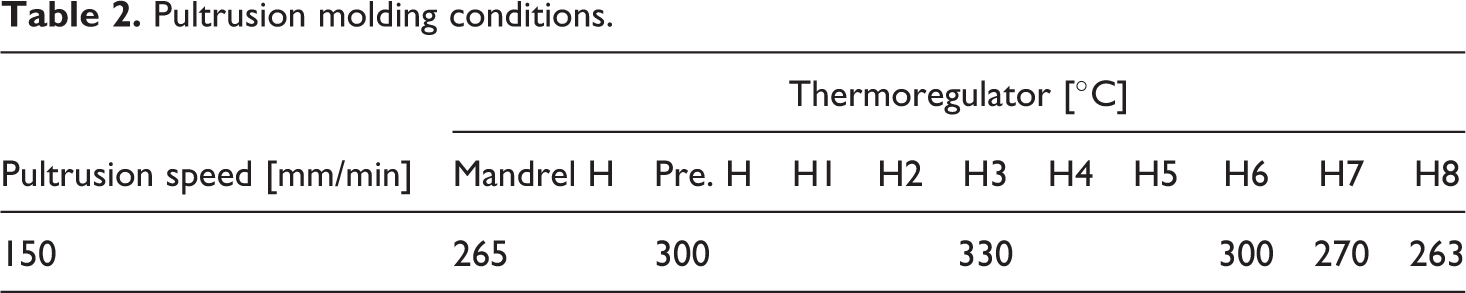
Figure 4 shows a schematic of the pultrusion molding die. The dimensions of the die were a total length of 645 mm, inlet diameter of 28 mm, straight part diameter of 18 mm, tapered part length of 450 mm, taper angle of 0.64°, and mandrel diameter of 15 mm. The thickness of the braided cylinder walls was 1.5 mm. Table 2 shows the molding conditions. The temperature of the die was 330°C in the tapered part for heating the resin above the melting point, with the temperature gradually decreasing in the straight part to below 265°C, which is the melting point of PA66 resin, at the outlet. The braided fabric was woven around the mandrel using the intermediate material that was used to make the unidirectional test specimens. Four layers were formed at a braid angle of 30° using a 16-bobbin braiding machine to achieve a packing ratio of 104%. Impregnation was accelerated by adding pressure in the thickness direction of the intermediate material by setting the filling ratio to 100% or more. Extraction molding was performed when more than 100% of the surplus resin flowed out of the mold. To understand the impregnation mechanism of the pultrusion molding, the temperature history and the pressure applied to the pultrusion mold were measured during pultrusion molding. To understand the impregnation mechanism, the temperature profile and the pressure applied during the pultrusion molding were measured. The temperature profile inside the braided fabric was measured 1250 mm from the mandrel tip by inserting a thermocouple between the second and third layers of the braided fabric. Pressure measurements were taken using a pressure sensor fitted inside the die 455 mm from the die inlet near the tapered end. During pultrusion forming, a tensile load acts on the molded part, and breakage occurs if a tensile load is applied that exceeds the breaking load of the braided fabric. Therefore, the tensile force was calculated from the input power to the motor required to produce the rated output power. To evaluate the impregnation state of the molded part, the cross sections 800 and 1000 mm from the tip of the molded part were observed with a metallurgical microscope.
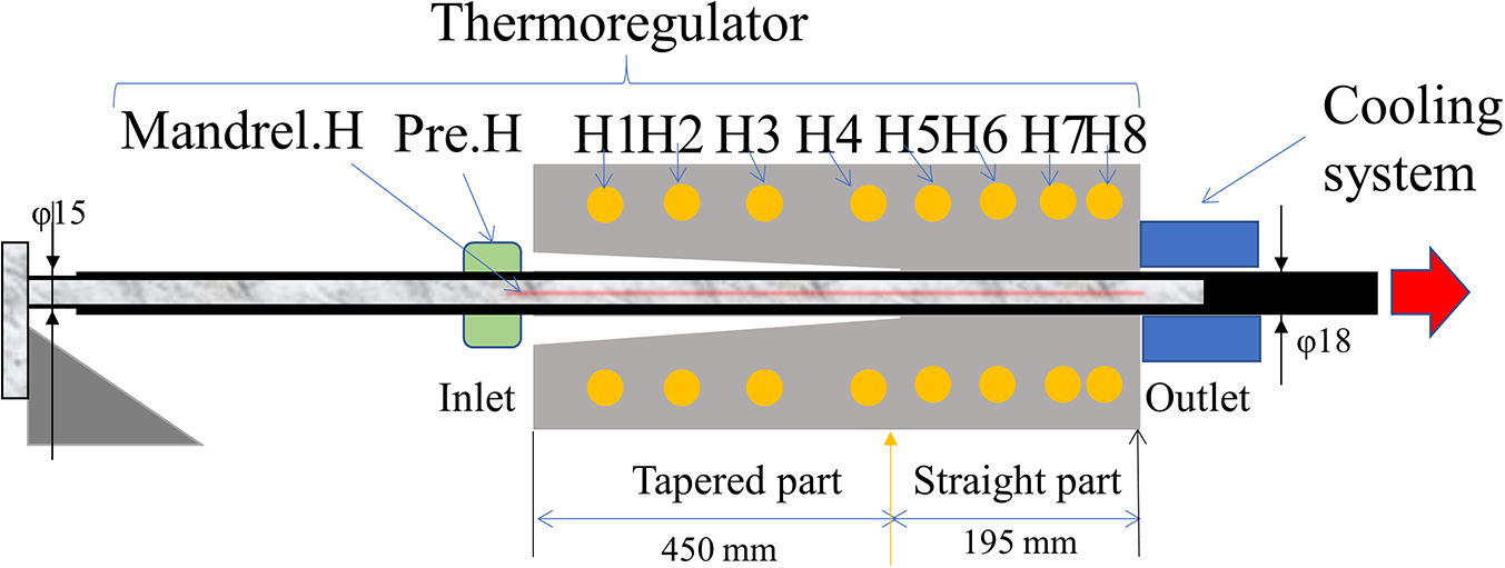
Schematic of pultrusion molding. Mandrel H represents the electric heater embedded in the mandrel, Pre H represents the heater at the entrance of the mold, and H1–H8 represent heaters embedded in the mold.
Pultrusion molding conditions.
Test methods
Method of measuring unimpregnated ratio
To investigate the effect of the intermediate material fabrication method and resin viscosity on the impregnation state, a cross section of the test specimen perpendicular to the fiber length direction was observed. The unimpregnated ratio was measured by image processing of the cross-sectional photographs. The unimpregnated ratio was defined as the ratio of the area of unimpregnated regions to the total cross-sectional area. A fragment of the specimen was cut and embedded in resin (EPOMOUNT, Refine Tec). The specimen was polished to a mirror finish using a table-top sample polisher (IM-P2, IMT Co. Ltd.), and then the polished surface was immersed in dilute sulfuric acid for around 10 min and the glass fibers were stained to make them easier to distinguish. A photograph of the test specimen cross section was taken using an inverted metallurgical microscope (GX41, Olympus). The unimpregnated ratio was calculated from the unimpregnated area ratio using image processing software (ImageJ, National Institutes of Health), by manually separating the boundary line between the resin and fiber area and measuring the areas. For some of the cross-sectional photographs, multiple microphotographs were taken with a microscope to create detailed pictures, and these were merged into a single image using imaging software (Photoshop, Adobe Systems). Figure 5 shows a photograph and schematic of the cross section. The cross section of a glass fiber bundle is in the center, and there are gaps between the fibers in the center of the bundle that have not been filled with resin, which is defined as the unimpregnated area. Ten or more fiber bundles were measured to obtain the ratio for each specimen.
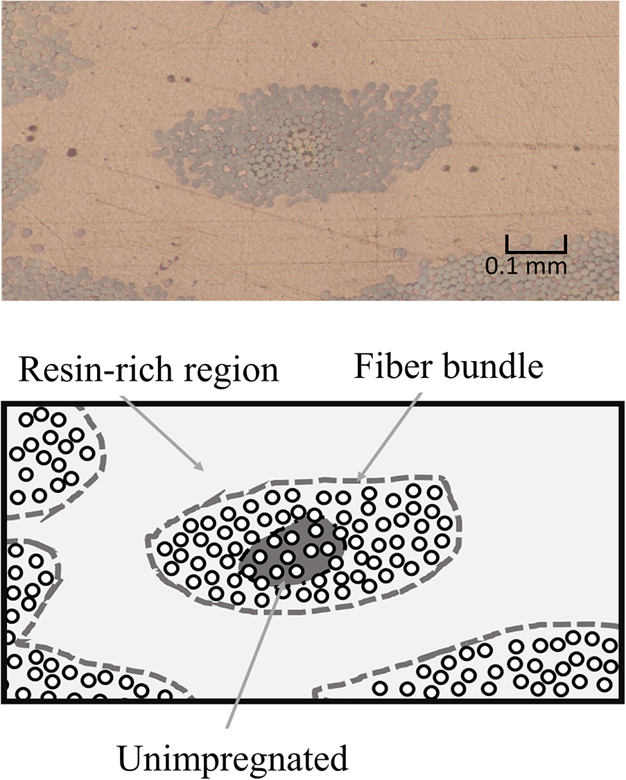
Photograph (top) and schematic (bottom) of cross section.
Unidirectional test specimen tensile test
Tensile testing was performed to investigate the effects of the intermediate material fabrication method and resin viscosity on the mechanical properties. This test was conducted in accordance with JIS K 7073. The test specimens 200 mm long and 20 mm wide were cut with the fiber direction as the long-edge direction. Aluminum tabs 50 mm long, 20 mm wide, and 1 mm thick were attached with epoxy adhesive to both sides at both ends of the test specimen, and then it was left for at least 24 h to harden. A general-purpose foil strain gauge (KFGS-10-120-C1, Kyowa Ltd.) was used to measure the strain with the distance between reference points set to 100 mm. A universal tester (Model 5969, Instron) was used, and the tests were performed at a speed of 1 mm/min. Five measurements were taken for each specimen.
Measurement of fiber volumetric content fraction
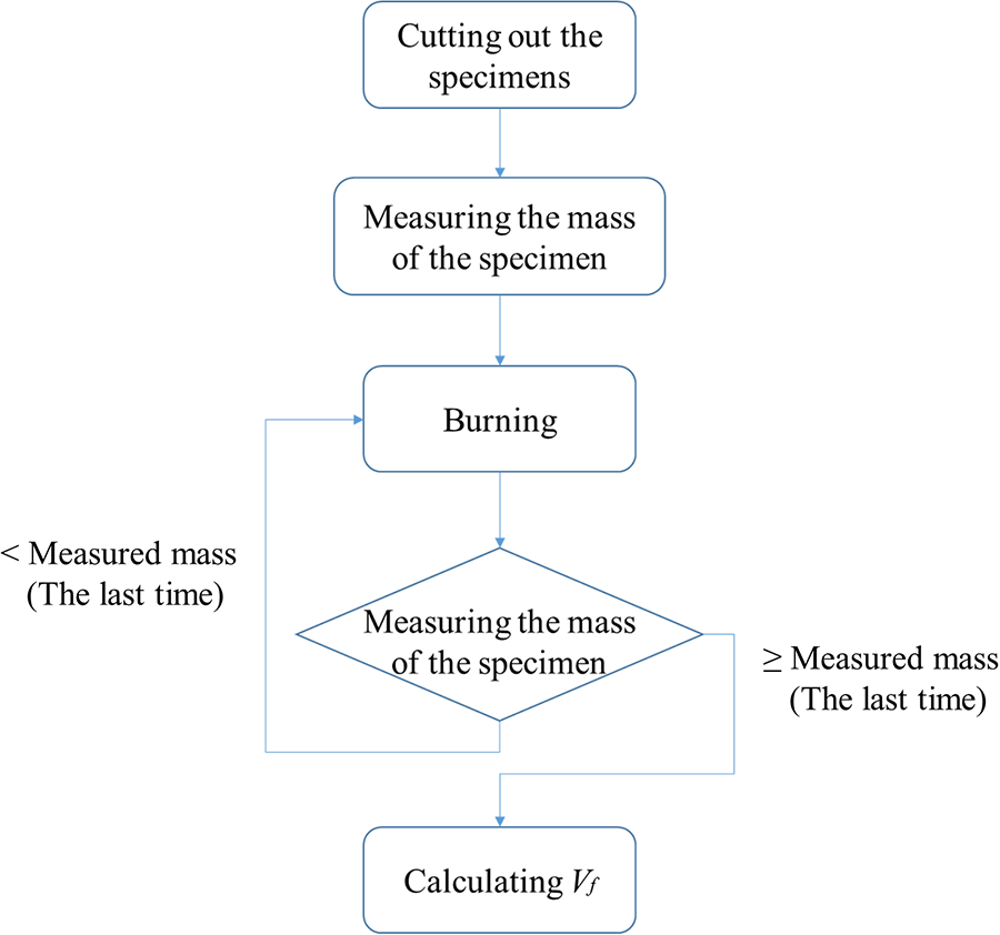
The fiber volumetric content fraction (Vf) of the test specimen after molding was measured using the baking method (Figure 6). The mass of the cut off test specimen was measured, and then the specimen was heated at 500°C in a muffle furnace to decompose the resin thermally. The masses of the reinforcing fibers and resin in the test specimen were calculated from the masses of the test specimen before and after baking by

where Wf is the fiber mass content fraction, ρc is the density of the test specimen, and ρf is the glass fiber density.
Flowchart of baking method.
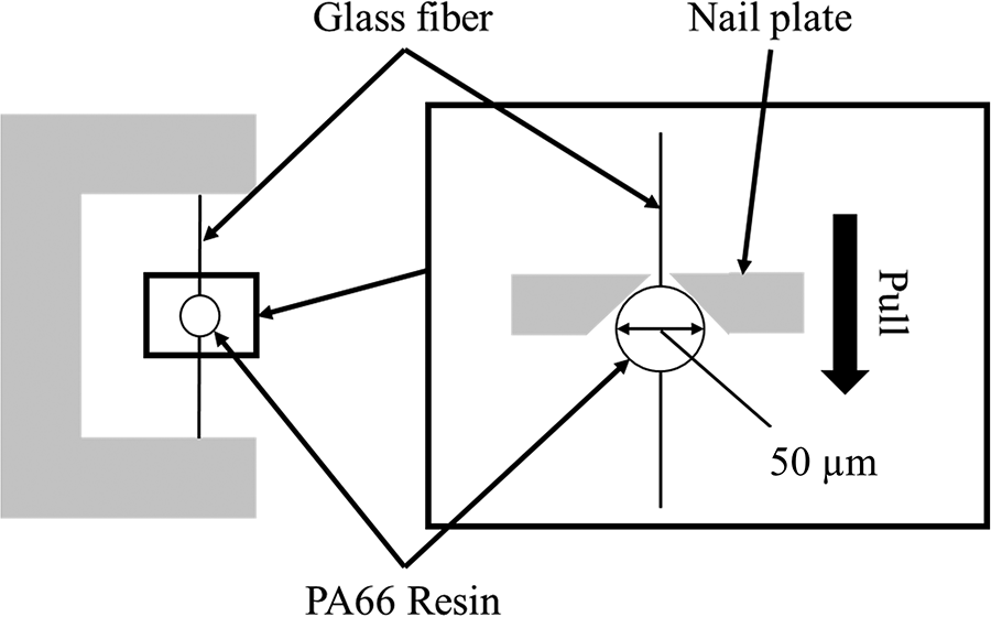
Microdroplet test
To investigate the interfacial properties of the two resins, microdroplet tests were performed (Figure 7). A single fiber under tension was affixed to a C-shaped metal plate, and PA66 resin was melted on a hot plate and adhered to the fiber. The temperature of the hotplate was set to 300°C for the low-viscosity resin and 350°C for the high-viscosity resin. Tabs fitted to the tester were hooked around the resin, and the interfacial shear strength was found by separating the fiber/resin interface by applying a tensile load and dividing the maximum load by the area of the interface. The drop size was 60–80 mm and the shear strength was measured. More than 30 data points were obtained for each specimen. The following formula was used for calculating the interfacial shear strength.

Here, τ is the interfacial shear strength, F is the pull load, d is the fiber diameter, and L is the length of the droplet.
Schematic of microdroplet test.
Braided pultrusion molding test specimen bending test
To investigate the effect of the impregnation state of the molded part on the mechanical properties, a four-point bending test was performed (Figure 8). To prevent local breakage directly under the indenter points of the cylindrical specimen, metal rods were placed into both ends of the specimen, and the tests were conducted with a distance between the fulcra of 300 mm, a distance between the load points of 100 mm, and at a test speed of 2 mm/min. Three measurements were taken for each specimen.
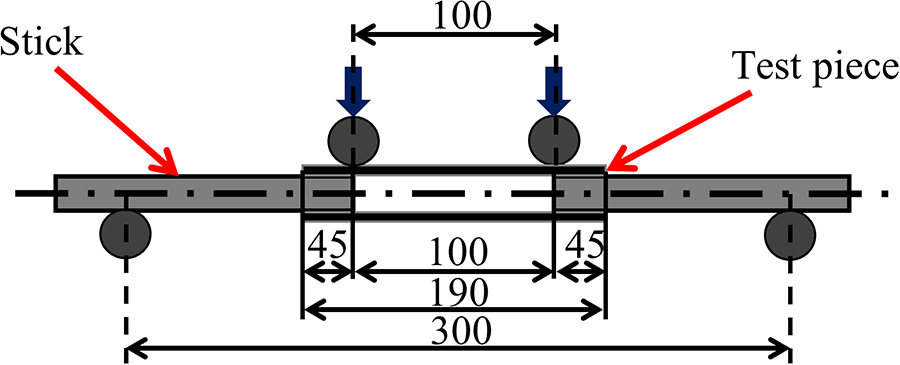
Schematic of four-point bending test.
Measurement of impregnation behavior at interlaced points in unidirectional press molding
Next, we investigated the effect of the interlaced points in the yarn on the impregnation. Figure 9 shows schematics of the two materials that were used.
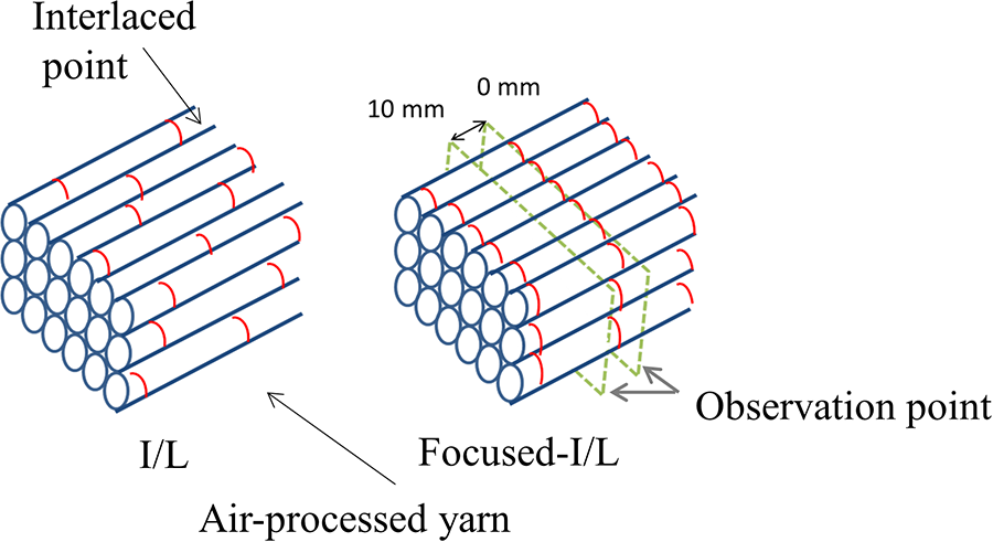
Schematic of unidirectional material with interlacing points.
The interlaced points were aligned at the same position in the axial direction of the fibers, the cross sections were observed. The test specimen with the interlaced points aligned at the same position is called Focused-I/L. In the Focused-I/L specimen, cross sections were observed where the interlaced points aligned (0 mm) and 10 mm from there where there were no interlaced points.
The molding conditions for the hot-press molding were set to a molding temperature of 285°C, pressure of 1 MPa, and molding time of 0 s. The molding was conducted using a short time and low pressure to produce a large unimpregnated region for clarifying the impregnation behavior.
Results and discussion
Unidirectional press molding
Measurement of unimpregnated ratio and fiber volume fraction
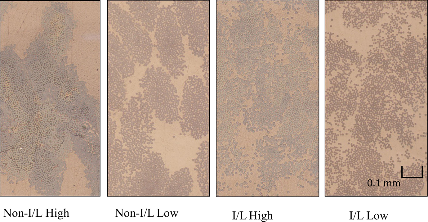
Figure 10 shows the cross-sectional photographs, and Figure 11 shows the unimpregnated ratios obtained from the cross-sectional photographs. For both the non-interlaced and interlaced specimens, the unimpregnated ratio was lower for the low molecular mass resin because the glass fiber bundle was impregnated more easily owing to the low viscosity and higher fluidity of the molten low molecular mass resin.
Photographs of unidirectional specimen cross sections.
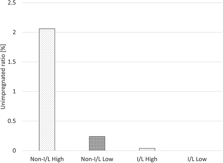
Unimpregnated ratios of the unidirectional specimens.
Furthermore, non-interlaced and interlaced specimens with the same resin were compared, and the interlaced specimens had much lower unimpregnated ratios. This result was explained by the shorter distance required for complete impregnation by the molten resin (impregnation distance) in interlaced specimens, and thus impregnation was easier because the fibers were mixed where the fiber bundles were interlaced (Figure 10). In the non-interlaced specimens, the fiber bundles were aligned, and the impregnation distance was longer because the fibers were not mixed, resulting in a higher unimpregnated ratio.
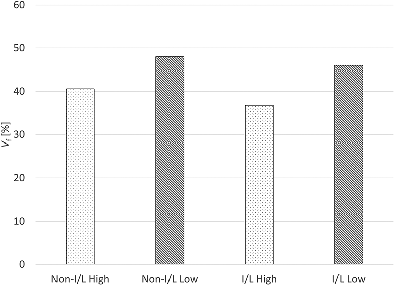
Figure 12 shows Vf for the test specimens. Vf was lower for the high-viscosity resin specimens than for the low-viscosity resin specimens and was lower for interlaced specimens than for non-interlaced specimens. This result was explained by the low outflow of resin outside the molded parts because interlacing of the fiber bundles made impregnation inside the reinforcing fiber bundles easier. Furthermore, Vf was low when the viscosity of the resin was high because the fluidity was low and the outflow of resin from the molded part was small.
Vf of the unidirectional specimens.
Mechanical properties
Figure 13 shows the fracture morphologies of the test specimens. In all specimens, fractures developed lengthwise along the fiber direction, characteristic of unidirectional test specimens, in the broom-like fracture mode. Exposure of the reinforcing fibers from the test specimens after failure was observed in only the Non-I/L High specimen. The glass fibers in the unimpregnated regions in this specimen were observed after failure because the unimpregnated ratio was high (Figure 11). Fracture tests on unidirectional test specimens often show this fracture aspect of the fibers spreading outward due to the apparent increase in volume.
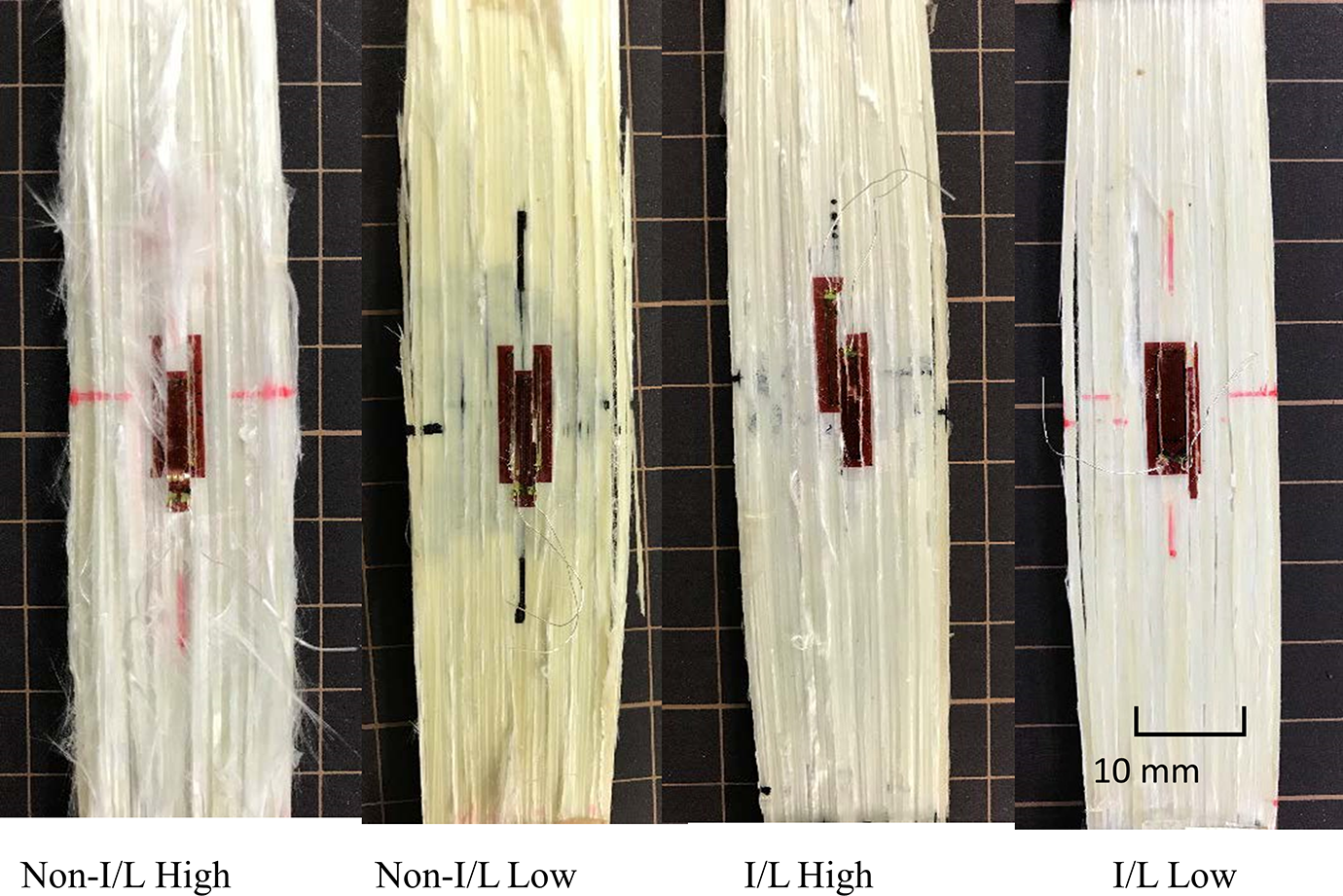
Fracture morphology of the unidirectional tensile test specimens.
Figure 14 shows the stress-strain graphs obtained from the tensile tests. The pseudo strain was calculated by dividing the displacement by the distance between the reference points (100 mm). In all the test specimens, the stress increased linearly in the initial stage, reached the maximum load while exhibiting non-linear behavior, and then underwent ultimate failure.
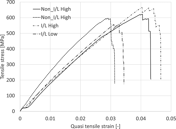
Relationship between tensile stress and quasi-tensile strain in unidirectional specimens.
Figure 15 shows the quasi-elastic modulus results obtained from these line graphs. In the low-viscosity resin specimens, the quasi-elastic moduli were higher than for the high-viscosity resin specimens. Furthermore, for the same resin, the values were lower for the interlaced specimens. The differences in resin viscosity and intermediate material internal structure affected the amount of resin outflow, and the mechanical properties depended on Vf. Therefore, we investigated the relationship between the quasi-elastic modulus and Vf (Figure 16) and the quasi-elastic modulus increased with Vf.
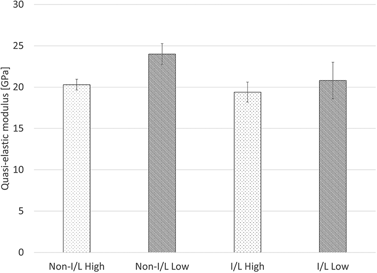
Quasi-elastic moduli of the unidirectional specimens.
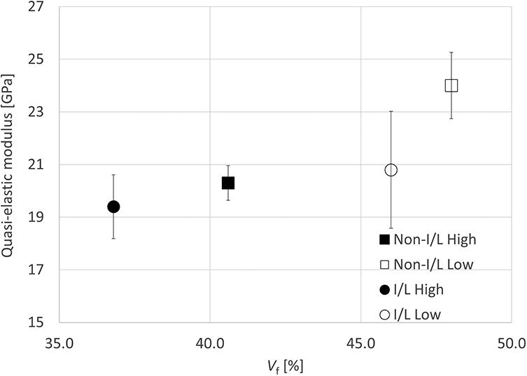
Correlation between quasi-elastic modulus and Vf in the unidirectional specimens.
Figure 17 shows the tensile strength results. For low-viscosity resin, the interlaced specimens exhibited a lower strength than the non-interlaced specimens, and for high-viscosity resin, the interlaced specimens exhibited a higher strength. The effects on the tensile strength of the fiber strength, fiber volume fraction, and unimpregnated ratio of the fiber were considered.
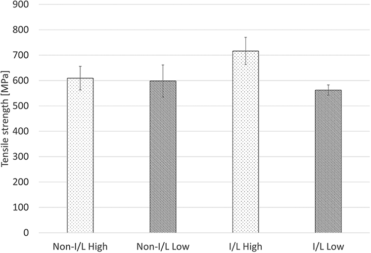
Tensile strengths of the unidirectional specimens.
Figure 18 shows the strength of the reinforcing fibers alone in each intermediate material. The strength was calculated from the tensile tests of the intermediate materials using the following equation of the rule of mixtures for strength.

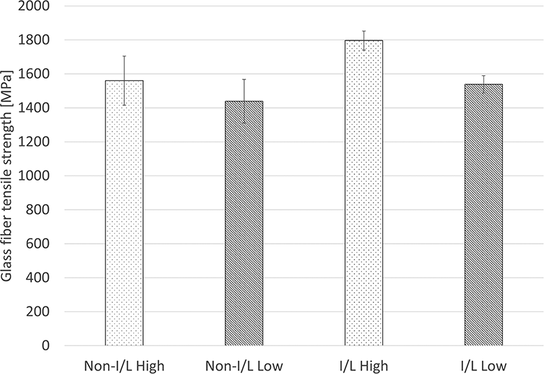
Correlation between the tensile strength of the molded part and the composite yarn tensile strength in the unidirectional specimens.
Here, Ff is the glass fiber tensile strength, Fc is the composite yarn tensile strength, and σm is the tensile strength of resin fibers.
Comparing the high- and low-viscosity resin materials showed that the I/L-processed intermediates had stronger reinforcing fibers. This is because the non-I/L reinforcing fibers are more easily damaged during the processing of the intermediate materials because the reinforcing fibers are more exposed. Both I/L and non-I/L intermediates showed lower tensile strength with low-viscosity resin fibers. This is probably because the low-viscosity resin fibers were softer during the composite yarn processing from the I/L process to winding, which can easily result in scratches and other damage to the glass fibers.
The theoretical strength of each specimen after molding was calculated from the rule of mixture, considering the fiber strength and fiber volume content, and normalized by dividing the experimental values of each specimen by the theoretical values. The achievement rate of the theoretical strength was calculated using the following formula.

Here, Rts is the achievement rate of the theoretical strength and Ft is the experimental tensile strength.
The unimpregnated ratio, which affects strength, reached a maximum of 2% (Figure 11), but because Patou et al. showed that an unimpregnated ratio of 3.5% or less does not affect tensile strength, it was excluded as a factor in this study. 15
The theoretical strength results are shown in Figure 19. The strength of I/L High was almost 100%, but that of Non-I/L High with the same fiber strength was about 18% lower than the theoretical strength. This may be due to a bias in the distribution of glass fiber in the Non-I/L High specimens, based on the cross-sectional photographs in Figure 10. In addition, the tensile strength of the low-viscosity resin may have been lower than the ideal strength because of the interfacial shear strength between the fiber and resin caused by the difference in the base resin. Figure 20 shows the interfacial shear strength obtained from microdroplet tests with the glass fibers used in this study and high- and low-viscosity resins. The interfacial shear strength of the low-viscosity resin was about 40% lower than that of the high-viscosity resin. Microscope images confirmed that fractures occurred at the interface between the fibers and the resin.
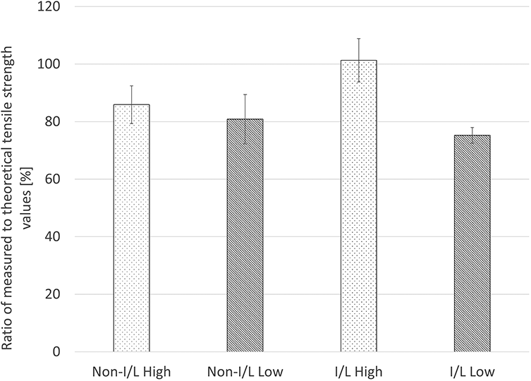
Ratio of measured to theoretical tensile strength values.
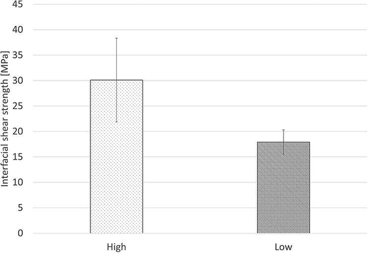
Interfacial shear strength of high- and low-viscosity resin fibers in the unidirectional specimens.
Impregnation behavior at interlaced points in unidirectional press molding
Figure 21 shows cross-sectional photographs of the Focused-I/L High specimen at 0 and 10 mm. The circled fiber bundles were assumed to be the same continuous fiber bundles based on their position in relation to the surrounding fiber bundles. Although there was an unimpregnated region at 10 mm, the impregnation was virtually complete at the interlaced point (0 mm). This result shows that the impregnation started first and the amount of impregnation was higher at interlaced points compared with regions where the fiber bundles were parallel.
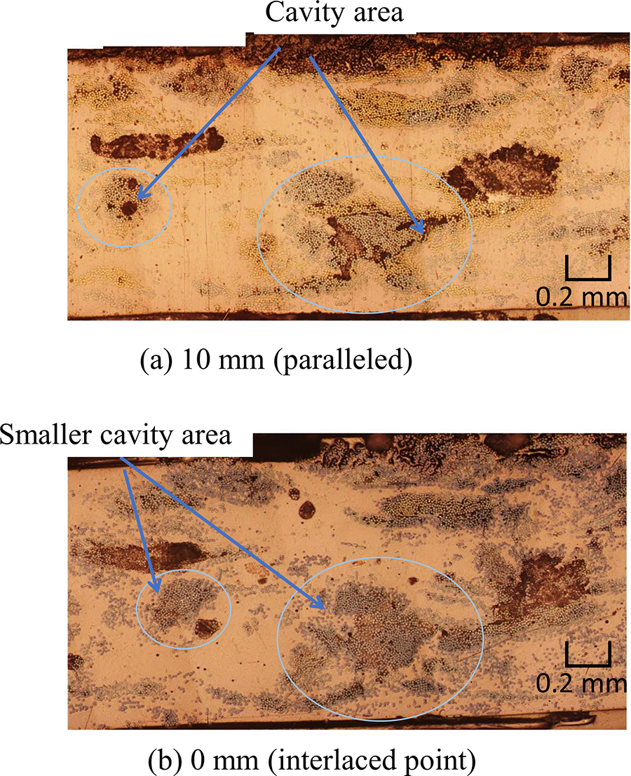
Photographs of cross sections in the unidirectional specimens.
Braided pultrusion molding
Pulling force and pressure profile in pultrusion molding
The pressure history during pultrusion molding is shown in Figure 22. In the pressure history of Non-I/L High and I/L High, the pressure began to increase from 450 mm when the base material started to pass through the straight part of the mold and reached its peak value at 695 mm when the base material started to slide on the mandrel. The pressure then dropped sharply, and after increasing again, it settled to almost 0 MPa for Non-I/L High and to 3 MPa for I/L High. For I/L Low containing the low-viscosity resin, no pressure was generated throughout the process.
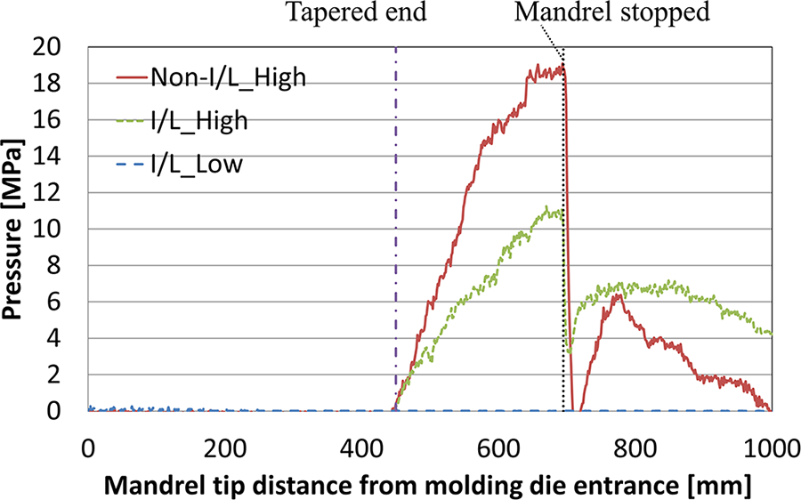
Pultrusion pressure history.
The pull-out force history is shown in Figure 23. For Non-I/L High and I/L High, the force gradually increased from 450 to 750 mm, with the peak value at around 750 mm. Subsequently, the force for I/L High became steady, but that for Non-I/L High kept decreasing and eventually became steady.
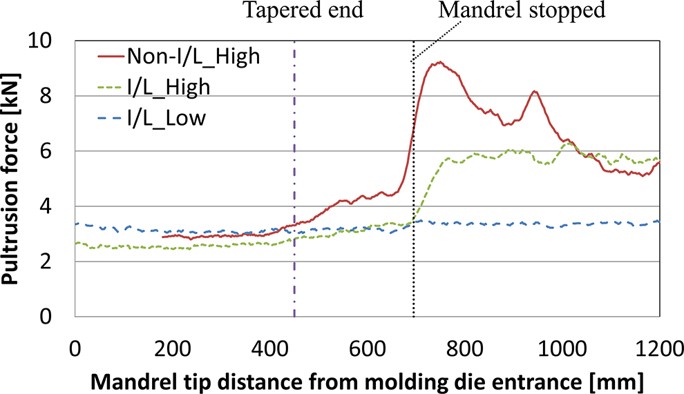
Pultrusion force history.
Cross sections
To investigate whether the same properties could be produced in pultrusion molding by using the intermediate material for which the impregnation and mechanical properties had been investigated using unidirectional material, we performed braided pultrusion molding and made cross-sectional observations of the molded parts (Figure 24). There were differences in the resin-rich regions under each set of conditions. Figure 25 shows the correlation between the unimpregnated ratio and the area of resin-rich regions in the outer layer. The measured area was 17.5 to 18 mm in diameter. Comparing the results using the I/L High specimen as a reference, the unimpregnated ratio and resin-rich area were reduced by interlacing. Furthermore, when low-viscosity resin was used, both the unimpregnated ratio and resin-rich area decreased. The unimpregnated ratio results were the same as for the unidirectional molding results, and there were interlaced points in the pultrusion molding and impregnation was higher with low-viscosity resin.
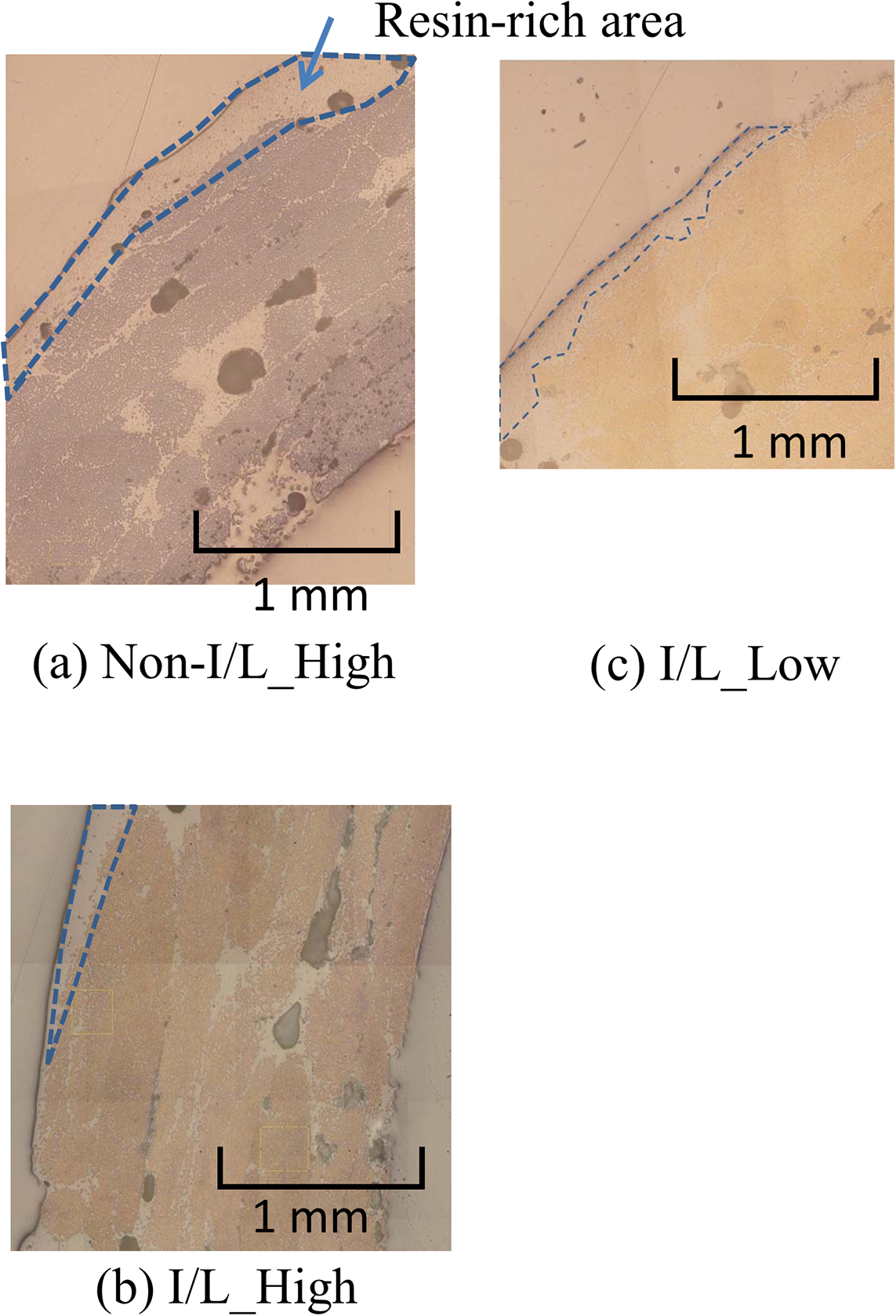
Photographs of cross sections of pultrusion-molded braided specimens.
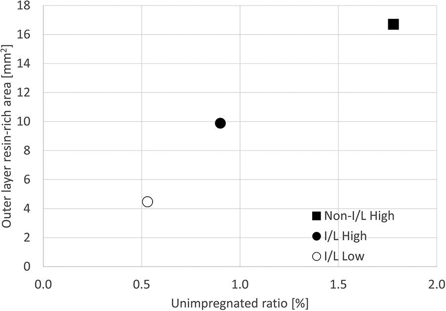
Correlation between area of resin-rich regions in the outermost layer and unimpregnated ratio in pultrusion-molded braided specimens.
Impregnation speed
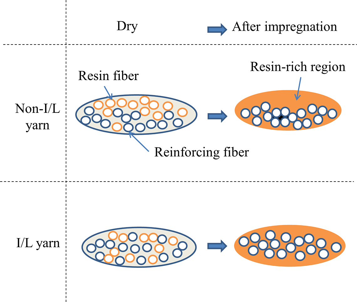
There were large resin-rich regions between the fiber bundles under all conditions. This was because the braiding structure prevented the gaps between the fiber bundles from being filled, even when the resin was melted and the reinforcing fiber bundles were aligned parallel. The area of the outer layer resin-rich regions in the Non-I/L High specimen was the largest (Figure 24). Figure 26 shows a schematic of the microscopic resin flows in the non-interlaced and interlaced composite yarns. In the interlaced composite yarn, the reinforcing fibers and resin fibers were mixed by interlacing, and the impregnation distance was short. In contrast, in the non-interlaced composite yarn, the impregnation distance was longer because the reinforcing fibers and resin fibers were only aligned, impeding the impregnation. In this case, resin-rich regions were formed. Gutowski’s model incorporates the capillary effect into the resin flow according to Darcy’s law and includes the degradation of the impregnation rate due to nesting of the fibers caused by the resin flow toward the inside of the fiber bundles. Impregnation time (Δt), which is the time required for complete impregnation, was determined using the following prediction formula. 13

Here, k^* is the Kozeny-Carman constant, Va is the maximum fiber volumetric content fraction, rf is the fiber radius, η is the coefficient of viscosity, ΔP is the pressure drop inside the porous body, and Id is the impregnation distance.
The parameters changed by interlacing were Id and Vf. Therefore, Vf was measured inside the fiber bundle from the cross-sectional photographs by image analysis. The reinforcing fibers and resin were binarized in the images, and measurements were taken at five braided layers from the inner to the outer layers, obtained by dividing the radial direction of the cylinder into five equal parts (Figure 26). For the high-viscosity resin specimens, Vf increased on the inner diameter side. The resistance to pultrusion, regarded as the pultrusion force, is shown in Figure 27. The pultrusion force was correlated with the behavior of Vf, confirming that the reinforcing fiber bundle aggregated on the inner diameter side and Vf tended to increase with increasing pultrusion force. However, for the low-viscosity resin specimens, which were formed with a low pultrusion force, Vf did not increase on the inner diameter side.
Schematics of microscopic resin flow in non-interlaced and interlaced yarns in braided specimens.
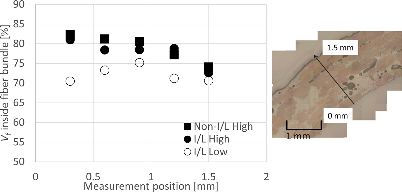
Correlation between Vf inside the fiber bundle and measurement position in pultrusion-molded braided specimens.
This was because when the pultrusion force was high, Vf was concentrated on the inner diameter side, and macroscopic resin flows dominated because it was difficult for microscopic resin flows to occur. Microscopic resin flow refers to the flow of resin into the glass fiber bundle during impregnation. Macroscopic resin flow refers to the axial flow along the fiber axis, such as back-flow (excess resin flowing backwards and toward the mold entrance) and resin flow around the fiber bundle.16,17 The area of the outer layer resin-rich region increased and the unimpregnated ratio increased at the same time in the Non-I/L High specimen through this process.
Bending strength
Figure 28 shows the the results of the bending test. Previous studies have observed a linear relationship between bending strength and unimpregnated ratio, and we observed a linear relationship for unimpregnated ratios of 1% and higher, and the effect on the unimpregnated ratio was small below 1%. However, from the relationship between the bending strength and unimpregnated ratio (Figure 28), the bending strength of the I/L High specimen was higher than that of the I/L Low specimen despite the unimpregnated ratio being less than 1%. However, I/L Low had a higher flexural strength compared with the other specimens. Therefore, we investigated factors other than unimpregnated ratio.
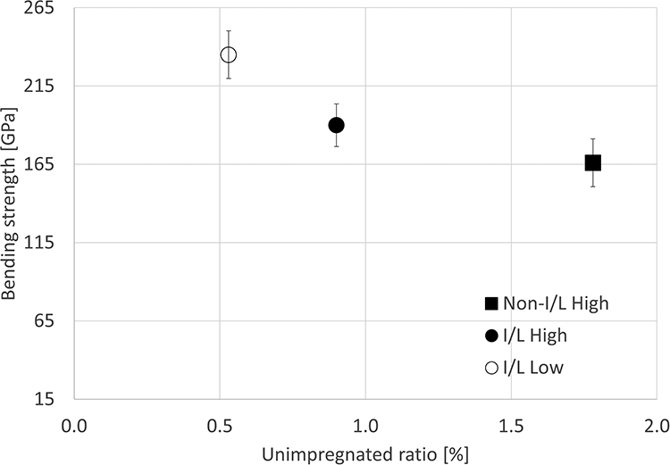
Correlation between bending strength and unimpregnated ratio in pultrusion-molded braided specimens.
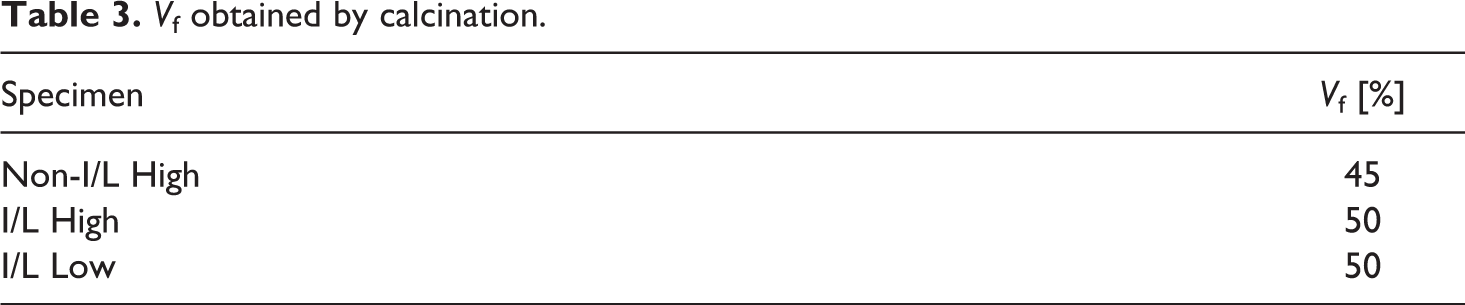
We used the baking method to measure the effect of Vf on the overall molded parts. The results are shown in Table 3. Only the Non-I/L High specimen exhibited a low Vf, and there were no differences between the I/L High and I/L Low specimens. However, in the results in Figure 27, the Vf values in the glass fiber bundles were lower in each layer in the I/L High specimen than the I/L Low specimen. This was because in the I/L Low specimen, the glass fibers were dispersed and the resin-rich region areas were small, resulting in the higher bending strength.
Vf obtained by calcination.
Elastic modulus
Figure 29 shows the relationship between the elastic modulus and resin-rich area in the outer layer. The modulus of elasticity decreased as the resin-rich area of the outer layer increased. The distribution of high-modulus reinforcing fibers near the inner diameter reduced the bending moment of inertia in the high-modulus area due to the formation of resin-rich areas near the outer diameter. The apparent modulus of elasticity was reduced because of the reduction in the bending rigidity of the entire molded body.
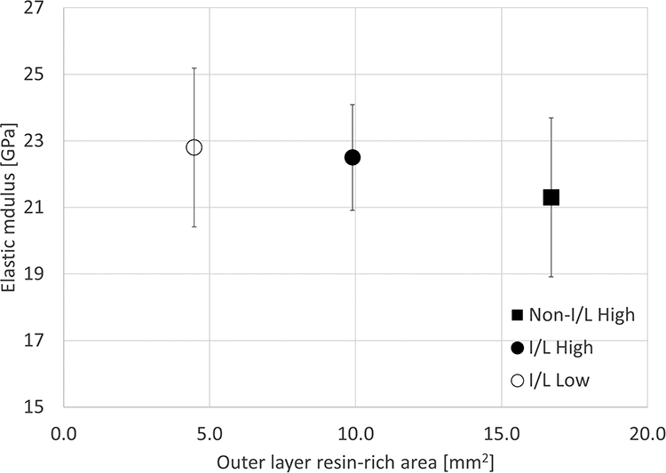
Correlation between the elastic modulus and the area of the outer layer resin-rich regions in pultrusion-molded braided specimens.
There was a correlation in the results for the unimpregnated ratio of the unidirectional press-molded part and braided pultrusion-molded part (Figure 30). Although many intermediate materials are required to evaluate braided pultrusion-molded parts, unidirectional press-molded parts can be evaluated using only a small amount of intermediate material. These results indicate that materials can be narrowed down by unidirectional press molding using a small amount of intermediate material as an initial evaluation for braided pultrusion molding.
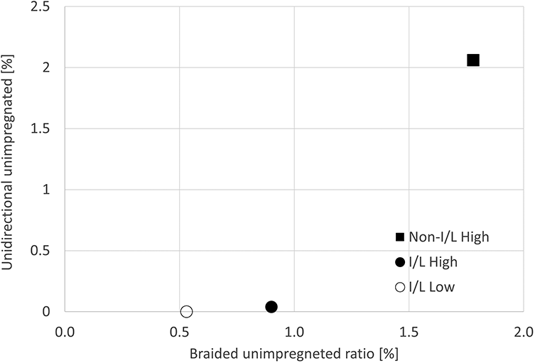
Correlation between the unimpregnated ratio in press-molded unidirectional specimens and pultrusion-molded braided specimens.
Conclusions
Methods for making composite yarns with matrix resins of different viscosities were investigated by using press molding and pultrusion molding to obtain fibrous intermediate materials with high impregnation and productivity. We found that low-viscosity matrix resin and I/L composite yarns were suitable as fibrous intermediates with high impregnation and productivity. This is because the reinforcing fibers and the resin were close together due to the interlaced fibers and their interfaced points, as well as the low viscosity of the resin, which facilitates the impregnation of the resin into the reinforcing fiber bundle. In addition, there was a correlation between the impregnation behavior in compression molding and pultrusion molding, and a relatively small amount of material could be used in compression molding, which is easy to work with, to select materials for pultrusion molding. Furthermore, besides the mechanical properties and degradation of Vf and glass fiber, the interfacial shear strength was found to have an effect, particularly on the tensile strength of unidirectional compression molded products.
Footnotes
Acknowledgements
We wish to acknowledge the timely help given by K. Morino and H. Ishihara in analyzing the large number of samples.
Author contributions
A.N., A.O., and T.S. designed the experiments. T.S. and K.Y. performed the experiments, analyzed the data, and wrote the paper. All authors agree with the final version of the manuscript.
Funding
The author(s) received no financial support for the research, authorship, and/or publication of this article.