
Abstract
Additive Manufacturing (AM) is increasingly responsible for a major evolution in how products are designed and manufactured. It offers flexibility and the ability to produce complex parts. Within AM, FDM (Fused Deposition Modeling) is widely used, but there are some limitations, both structural and superficial, such as the ladder effect, the need for support and heterogeneities. To reduce these limitations and obtain better quality parts, the non-planar FDM technique has been developed, in which the three axes are moved simultaneously without collision. This work aims to adapt a conventional FDM printer into a printer capable of producing non-planar layers by determining the main mechanical characteristics of the printer and the main parameters associated with the process. This makes it possible to exploit the advantages and benefits of the non-planar technique to design parts with different angles ranging from 10° to 80°.
Introduction
It is irrefutable that the ongoing advancement of industrial sectors and market dynamics significantly contributes to technological innovation and the progression and establishment of diverse manufacturing methodologies. 1 Additive manufacturing (AM) represents a process that has experienced substantial growth in its developmental trajectory and has consequently been implemented across various domains, including architecture, aeronautics, the automotive industry, engineering, and design, among others. 2
Various methodologies have been formulated over time that are predicated on additive manufacturing principles. Among these processes, FDM is particularly noteworthy.3,4 FDM constitutes an extrusion-based manufacturing technique that employs thermoplastic base materials, typically in the form of filament housed on spools. 5 Numerous categories of FDM printers exist, each characterized by distinct operational and printing methodologies. For instance, Cartesian printers operate through linear motions across three axes, 6 whereas polar printers utilize a polar coordinate framework for printing. 7 Conversely, the integration of a robotic arm in FDM applications affords the advantage of increased degrees of freedom (DOF), enabling a broader range of movements beyond mere linear motions on the three axes.8,9
The printing technique, as delineated by the FDM process, has experienced a significant surge in popularity across diverse sectors, being implemented in a multitude of concepts. This increase in prevalence can be attributed to the plethora of advantages it offers when juxtaposed with alternative manufacturing methodologies. 10 The primary benefits associated with this approach pertain to the minimization of material waste, thereby enhancing sustainability, 11 the capacity to execute intricate geometries through a layer-by-layer methodology, 12 adaptability, and rapid production rates, in addition to the feasibility of employing various types of materials and filaments. 13 Nevertheless, the presence of a ladder effect on the surface, the necessity for support structures, and the occurrence of a heterogeneous structure owing to the unavoidable formation of pores, which are characteristic of the manufacturing process, or temperature fluctuations during extrusion, render this methodology more intricate, encompassing numerous variables and parameters. 14
Upon closer examination, the potential for such meticulous parameterization of FDM printing renders it a versatile process with substantial opportunities for advancement and innovation. 15 Moreover, numerous challenges typically arise during FDM printing, including extrusion issues, adhesion difficulties, surface quality concerns, and mechanical complications, among others. 16
Advancements in technology and increased community engagement with the FDM process have led to the continuous development of methodologies to optimise this process and address its limitations. 17 Non-planar FDM printing involves fabricating non-planar layers of varying thicknesses. 18 This printing methodology is referred to by several names: Curved Layer Fused Deposition (CLFD), 19 Curved Layer Fused Deposition Modeling (CLFDM) 20 and Curved Layer Fused Filament Fabrication (CLFFF). 21
Numerous investigations have been conducted regarding this subject, including methodologies aimed at enhancing surface finish and mechanical integrity, 22 as well as the elimination of support structures. 23 The research conducted by Chakraborty et al. 24 predominantly focuses on the development of a non-planar extrusion trajectory to implement the CLFDM rapid prototyping technique. By employing a parametric surface, non-planar paths were generated extending from the external surface to the internal regions of the object. Consequently, the authors assessed which technique possesses the capacity to fabricate components exhibiting enhanced durability, attributable to the extended length of the formed paths and the increased interlayer contact area, in addition to the non-planar configuration of the layers, mitigation of the staircase effect, and the reduction in the number of layers and overall printing duration. Conversely, Khurana et al. 25 proposed a concept of non-planar printing suitable for three-axis printers, which entails the simultaneous movement of the x, y, and z axes. Following extensive experimentation, it was determined that non-planar printing can yield objects with superior mechanical resistance when subjected to forces applied perpendicularly to the layer interface (forces exerted along the Z-axis of the printed component).
To eliminate the stair-stepping effect caused by conventional planar printing, Micali and Dornfeld 26 created a 3D path that follows the surface of the object being printed. This technique was developed for three-axis printers, the most common, and is based on CNC process path planning. The technique addresses the printer’s mechanical limitations to avoid collisions. This printing methodology allows for increased resolution of printed objects without making any changes or modifications to the printer’s components or design. Another advantage of this technique is its usability with a wide variety of printers, as the path is generated using a G-CODE algorithm.
Huang et al. 27 This study used a combination of planar layers (at the base) and non-planar layers (on the outside) to improve the surface quality of the object, eliminating the staircase effect. To achieve this, each surface of the STL mesh was characterized as a portion of the bottom, side, or top surface. To distinguish the sides from the top, the user can establish a reference angle. The top layer is shifted downward along the axis normal to the surface until the desired number of layers is reached. To obtain the planar layers, the STL is divided into two parts. The top shell (made using a non-planar print) is removed, and the remainder is used to create an STL, which will then be sliced using a planar print. Manufacturing the object consists of printing a first planar part, which is then covered by the non-planar part.
Jin et al. 28 Focusing on achieving higher-quality surfaces, this study analyzed and optimized the generation of non-planar print paths. The main focus of the article was to study how non-planar layers are generated correctly, starting from the outer surface. To achieve this, the print head must always be perpendicular to the surface. Ensuring this condition is impossible on a standard three-axis printer, and collisions between the print head and the nozzle can occur. To avoid this interaction, three factors must be considered: print height, the angle relative to the non-planar layer, and the nozzle diameter. The conclusion was that in downward strokes, the layer height should be greater than in upward strokes. Although no printed objects were presented in the study, the result of this printing methodology results in a surface with reduced stair-stepping.
Using FDM printing with a non-planar methodology offers substantial benefits and provides effective solutions to the inherent constraints of this manufacturing technique. However, its full capabilities remain inadequately investigated and optimised. While there are many theoretical frameworks, the lack of software designed to improve path generation, particularly by utilising the potential of non-planar layers, prevents the comprehensive optimisation of FDM. As observed, existing printers that operate in layers impose limitations on both structural integrity and surface quality. The primary objectives of this research are therefore to identify the essential mechanical characteristics that must be modified in the printer to facilitate the implementation of the non-planar printing technique and to examine the critical parameters required for its effective application through the adaptation of a contemporary printer to optimise the non-planar printing parameters.
Ender V2 printer: Planar to non-planar printing adaptation project
Equipment analysis
To initiate the project’s progression, an examination of a standard FDM printing apparatus was conducted. For this analysis, an Ender 3 V2 Cartesian printer (Grit 3D, Pakistan) was employed, as illustrated in Figure 1. This device possesses a printing capacity measuring 220 × 220 × 250 mm3. Furthermore, it exhibits an external dimension of 475 × 470 × 620 mm3 and has a mass of 7.8 kg. Regarding its maximum operational temperatures, the 3D printing nozzle can attain a temperature of 250°C, while the print platform is capable of functioning at 100°C. The printer operates at a standard speed of approximately 30-60 mm/s, with its peak printing velocity reaching up to 180 mm/s. Ender 3 V2 3D printer.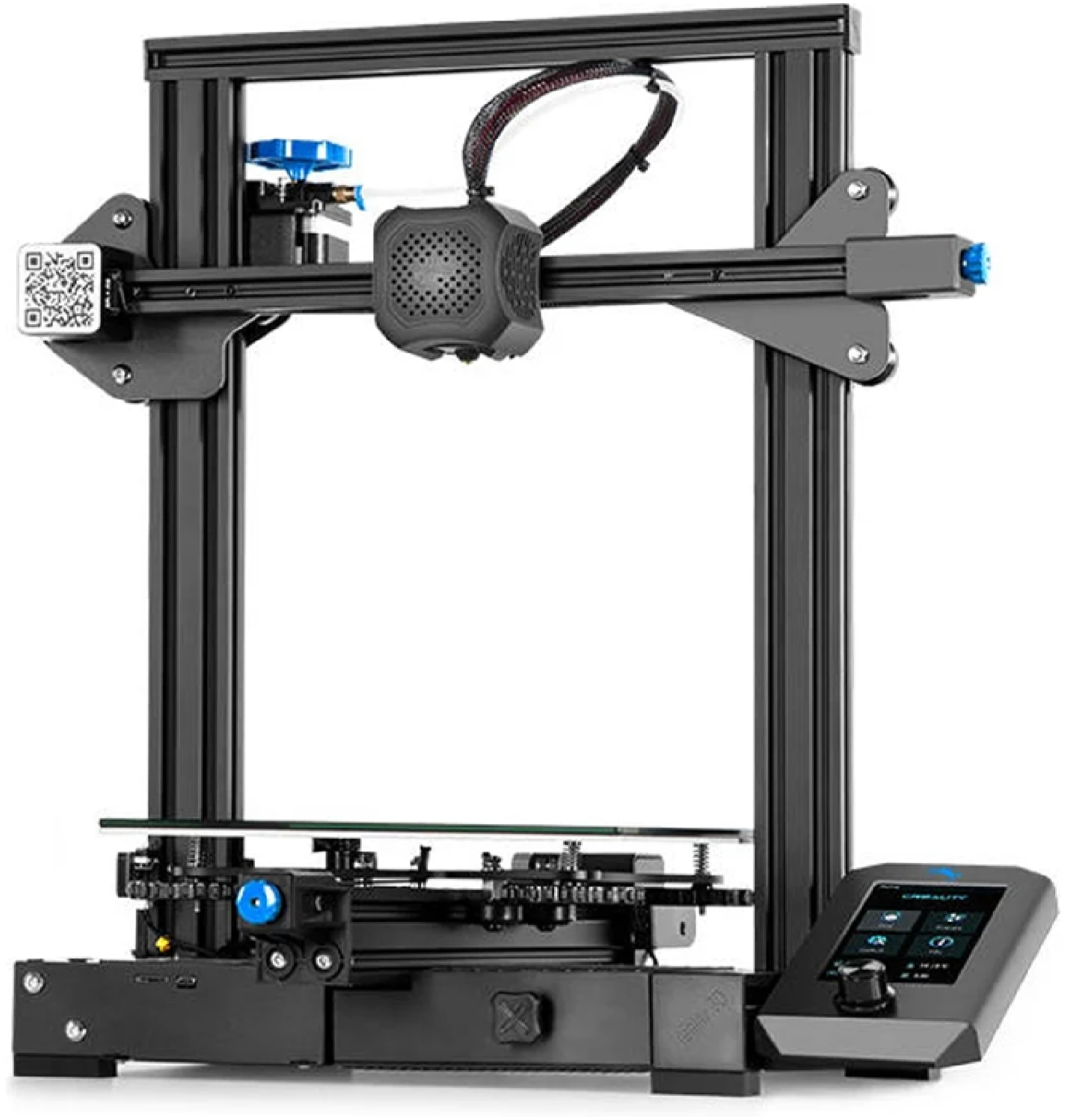
A considerable number of modifications have been made to enhance the printer’s performance. These modifications include changing the extrusion system from Bowden tube extrusion, as shown in Figure 1, to direct extrusion, as shown in Figure 2. This allows the material to be deposited along three-dimensional paths, i.e. it is possible to redirect the deposition head and thus build objects on curved platforms and create more complex structures.
29
Original extruder head.
Furthermore, the glass print bed was adapted to a magnetic print bed with different coatings. It has a smooth surface on one side and a textured surface on the other (Figure 3). Different textures applied to the bed with magnetic printing.

Analysis of the printer’s mechanical limitations
For non-planar printing to be carried out, the printer head needs to move along the three axes simultaneously, without colliding with the object to be printed. However, the printing head housing of the Ender 3 V2 restricted the non-planar printing zone, which left only a non-planar printing angle and height of approximately 6.6° and 22.3 mm (Figure 4), respectively. In this way, the print head components were repositioned so that the non-planar printing area was optimized, for subsequent study of the associated parameters. Thus, there are challenges in obtaining non-planar paths, as without the adaptation carried out, when printing occurs from bottom to top, the previous layer would be damaged, from top to bottom, and it could damage the filament. In both cases, it would result in low surface quality.
28
Ender 3 V2 non-planar features.
Development of a solution to optimize non-planar print space: Nozzle and heating block analysis and print head components repositioning
Since the original print head of this printer has a reduced non-planar printing area, as with most three-axis FDM printers, solutions were studied to overcome this limitation and enable the printing of a wider variety of samples. To this end, the repositioning and replacement of print head components were considered to optimise the non-planar printing space.
Firstly, the nozzle and heater block were analysed, as these are the components closest to the printed object, and it was found that the nozzle geometry is a parameter to consider to obtain a larger zone of non-planar printing. For example, the common nozzle has a large rim around the extrusion hole and a low height relative to the heater block, which reduces the non-planar printing angle (Figure 5). (a) Common nozzle rim and (b) common nozzle height, originally from the Ender 3 V2 printer.
Therefore, the Vulcano-type nozzle was considered as a possibility for optimisation, since, when applied to the heating block studied, it is possible to obtain a greater non-planar printing height. It was observed that only part of the thread was inside the heater block, creating a cooling zone between the heater block and the end of the thread area of the nozzle, as with the use of cooling fins. However, the solution still did not seem to meet the original objectives.
Moreover, It was also decided to study the characteristics of a nozzle with a stainless steel tip. The use of this nozzle allows an increase in the height of the heater block as well as an almost complete threading of the heater block, as shown in Figure 6. Another reason for choosing this nozzle was the reduced edge around the extrusion hole. This allows more non-planar pressure angles to be obtained and analysed. Comparing the geometry of the two nozzles analysed, the nozzle with the stainless steel tip allows non-planar printing up to an angle of about 30° without the nozzle colliding with the printed object, while the Vulcano nozzle only allows non-planar printing up to about 20°. Figure 7 illustrates the difference. Nozzle’s height with a stainless-steel tip. Nozzle’s geometry: (a) stainless-steel tip and (b) Vulcano.

Once the nozzle was used and the maximum non-planar print angle and height had been defined, an analysis of the heater block was carried out. SolidWorks® 3D modeling software was used to create a three-dimensional model of the assembly and measure the maximum non-planar print angle. To measure this angle correctly, it was assumed that a silicone protector was applied to the heater block. This was done by looking at the furthest point from the heater block protection and removing the value of the non-planar print angle. The set of these components was then assembled, and a photograph of the area to be analysed was used to verify the accuracy of the values obtained in the 3D modeling software. It was concluded that the maximum non-planar compression angle was approximately 30.7°. Figure 8 shows the estimated and real angles. Non-planar printing angle: (a) estimated angle and (b) real angle.
After optimising the non-planar print angle of the heater block and nozzle, it was determined that they needed to be repositioned to further increase the non-planar print zone. A survey of the geometry and mounting dimensions of the components present in the print head was carried out so that they could be reproduced in SolidWork® software. Once reproduced, it was possible to analyse various designs to arrive at a solution that could be effectively implemented. To have a greater projection capacity so that the parts could be produced quickly and at a moderate cost, the possibility of producing the various components using an SLS printer and PA12 (SLS) material was granted.
Once the new position of the block and nozzle had been defined, as shown in Figure 5, the repositioning of the entire cooling system and consequently the design of the printer’s extrusion head was analysed. First, the heat sink cooling fan was analysed, which had to be slightly lowered. Then the filament cooling fan was also lowered slightly as it exited the extrusion hole. However, for this fan to continue to provide efficient cooling, it was necessary to redesign the air duct. The next step was to design a housing that would hold it in place and allow it to function properly. A simple, practical and lightweight solution was sought based on the fixing points of the housing. After a number of trials and experiments, a final design was achieved which, when all the components are in place, allows non-planar printing up to an angle of approximately 30° and a maximum non-planar height of 50 mm. All process modifications are represented by Figure 9. (a) Repositioning of the heat sink cooling fan, (b) Air guiding duct of the extruded filament fan, (c) Repositioning of the extruded filament cooling fan, (d) Design of the engineered housing and (e) final product.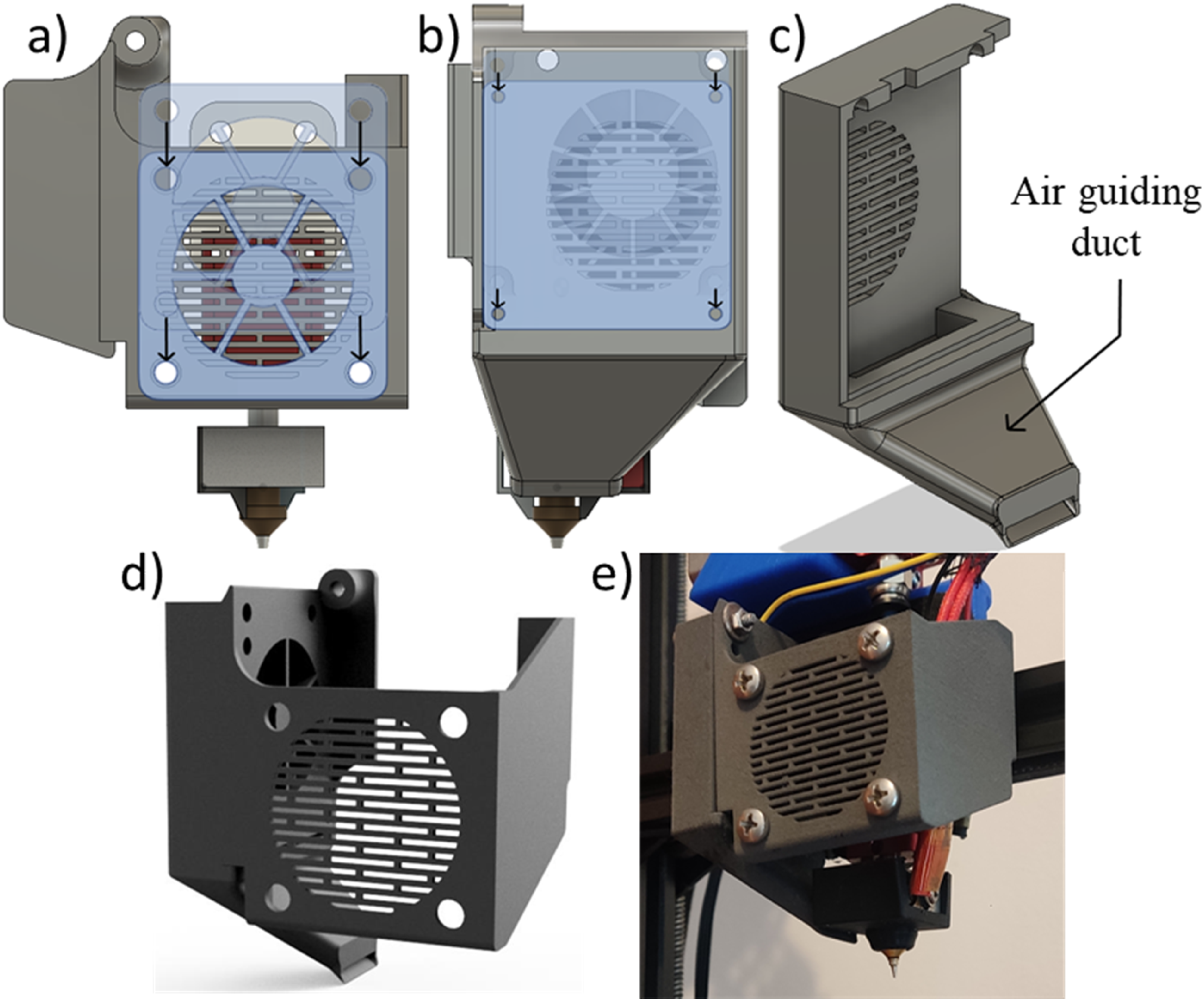
Printer calibration steps after printer adaptation
Calibrating the axes of a 3D printer is essential for ensuring print accuracy and quality. The process begins with calibrating the Z-axis, which determines the initial layer height. Bed levelling is also crucial, as an even surface ensures consistent filament deposition. This can be achieved by using a sheet of paper or a feeler gauge to adjust the height of the extruder nozzle relative to the bed at several points. Once levelling is complete, the X- and Y-axes are calibrated to focus on horizontal and lateral movement. This usually involves printing a test object to verify dimensional accuracy. If the dimensions are incorrect, the pitch of the stepper motors must be adjusted in the printer’s firmware using measurements and calculations to determine the exact number of steps per millimetre.
Extrusion calibration, which refers to the E-axis, is equally important and can be performed using a specific extrusion test to measure the amount of filament extruded against the amount requested in the software. Adjustments to extrusion multiplication can be made directly in slicing software such as Slic3r®. The software configuration was also adjusted for parameters such as layer height, print speed and extrusion temperature, as these directly impact the overall calibration. Calibration tools such as calibration cubes and temperature towers were designed and used to optimise printer parameters and ensure consistent, high-quality results.
All calibration procedures for printers adapted for non-planar printing are described in the following topics.
Determining extrusion multiplier and axes calibration
Some objects were selected for printing to calibrate the printer and determine the optimal printing parameters. A logical sequence of calibration steps was established for this purpose beginning with correctly levelling the print bed. To ascertain whether the firmware was compatible with the extrusion system, the extrusion multiplier was evaluated using a calliper to measure 130 mm along the filament path, which was then marked (Figure 10(a)). The printer was then switched on and heated up. Once hot, it was instructed to extrude 100 mm of filament to check that the amount extruded matched the target amount (Figure 10(b)). This measurement showed that the extrusion multiplier was slightly higher than intended at 103.66 mm (Figure 10(c)). The extrusion multiplier was therefore changed from 1 to 0.96 (Figure 10(d)). A second test with the updated multiplier showed that the extruded filament stroke was 99.6 mm, validating the multiplier. (a) Initial reference mark for determining the extrusion multiplier, (b) Order to extrude 100 mm of filament, (c) Position of the reference mark after the command to extrude 100 mm and (d) Updating the extrusion multiplier in the printer firmware.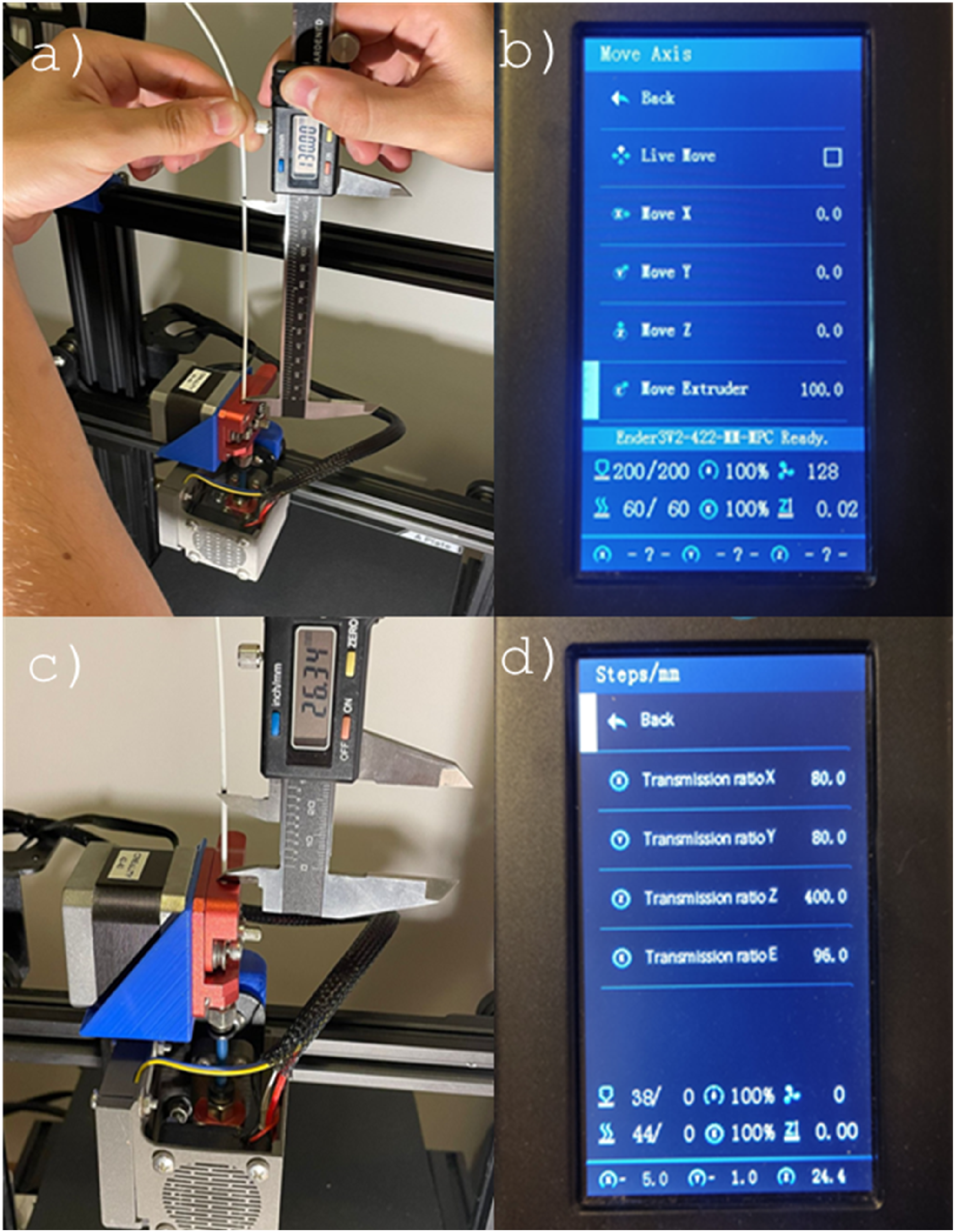
Print bed levelling
The Ender 3 V2 printer bed was levelled using the four manual height adjusters located at its four corners. A sheet of paper was used to analyse the defined points until they were all at the same height. The height limit was defined as the point at which slight friction was felt when slowly raising the adjuster at the end being analysed while simultaneously moving the sheet of paper. Levelling the Ender 3 V2 printer bed was then carried out using the four manual height adjusters located at its four corners. Using a sheet of paper, the defined points were analysed until they were all at the same height. The height limit was defined as the point at which slight friction was felt when moving the paper, by slowly raising the regulator at the end being analysed and moving the sheet of paper simultaneously.
Once the bed had been levelled relative to the nozzle, an analysis of the bed was carried out. Often, the bed is not completely flat due to warping, for example, resulting in slight deviations that can affect print quality. The latest firmware installed on the printer overcomes this problem by allowing the printing bed to be meshed. This is done by manually adjusting the height of 25 points, which are evenly distributed over the entire printing bed. The purpose of creating this mesh is to ensure that the printer always creates the first layer at the same height as the print bed, thus compensating for any irregularities. Figure 11 shows the mesh with the 25 reference points from the calibration and printing tables. Mesh with 25 reference points: (a) calibration points and (b) printing bed for irregularity compensation.
After verifying that the printing bed and its mesh were defined correctly, a new command had to be added to the G-code of the first print so that the mesh used during printing could be read. A test print was then carried out to ensure that everything was functioning correctly. To achieve this, a print bed calibration test was designed to analyse some of the most important factors. Once the bed had been calibrated and the mesh determined, a test print was made to verify the calibration’s accuracy by printing the designed test sample and superimposing it on a sheet of white paper, making all the print’s details clearer (Figure 12). Quality check of the printing bed calibration specimen.
Extrusion temperature calibration
Printing speeds for the manufacturing temperature tower used to analyse filament shrinkage.


Tower of the printed temperatures and their values.
Calibration of retraction parameters
With the extrusion temperature set to 200°C and the print bed levelled, the process of determining the various printing parameters began based on a standard profile. Due to the stringing effect observed in the temperature test, it was important to analyse the retraction parameters.
The printer needs to retract the filament several times while printing an object. Therefore, it is necessary to adjust the retraction speed and the amount of filament retracted to produce faultless prints. A test rig (Figure 14) has been designed to carry out this evaluation. It is capable of evaluating the effect of these two parameters on the printing of an object by retracting the filament as it moves between the two towers. 3D view of the apparatus used during the printing test to analyze filament retraction parameters.
To evaluate the effect of retraction on printing, several tests were carried out by varying only one parameter. The parameters used were 50 mm/s with the filament retracted by 1 mm and 2 mm, and 40 mm/s with the filament also retracted by 1 mm and 2 mm. Figure 15 shows the result obtained for each condition. Tower shrinkage test results obtained under the following conditions: (a) 50 mm/s and 1 mm, (b) 50 mm/s and 2 mm, (c) 40 mm/s and 1 mm, and (d) 40 mm/s and 2 mm.
For example, at a retraction speed of 50 mm/s and 1 mm of filament retracted, a slightly dense and fine stringing was observed, with the appearance of bubbles at the start of the circumferential print after displacement. At the same retraction speed, but with 2 mm of filament retracted, stringing continued, although less dense. The bubbles continued to appear, but with less emphasis. On the other hand, at a retraction speed of 40 mm/s, with 1 mm of filament retracted, there was an improvement in the stringing effect, although it persisted. As for the blobs, they remained similar to those in the previous test. At 2 mm, there was almost no stringing effect. The bubbles remained, but with reduced relief.
Maximum printing angle testing
Given that one of the objectives of this research is to apply non-planar printing techniques to enhance the FDM printing process, an experiment was also conducted to determine the maximum feasible angle for planar printing. Since 3D printing involves the layer-by-layer buildup of material, it’s crucial to ascertain the greatest possible gap between layers that results from the surface being angled. It is imperative to predict any scenario where this gap exceeds the optimal range and necessitates additional tools, like support structures, to ensure the object is printed seamlessly until completion.
To delve into this phenomenon and establish this critical value, a specialized test piece was devised (as illustrated in Figure 16), featuring a range of slopes from 10° to 80°. Besides examining these varying angles, the test also assessed the impact of different layer thicknesses, specifically 0.1 mm, 0.2 mm, and 0.3 mm, on each of the angular orientations. 3D visualization design of the specimen developed to determine the maximum printing angle on the sample (rectilinear surface on x-axis direction).
After optimizing the printing process, a “T-shaped specimen” (Figure 17) was printed to analyze additional characteristics and parameters of non-planar printing, such as the maximum print length without supports. This specimen has slanted top faces so that the slicing program can recognize the face along which to slice the object in question. Table 3 shows the printing parameters used to manufacture the T-shaped specimen. Analysis of the maximum printing length at 90° without supports, for a base size of 20 × 20 mm2. Printing parameters of the “T-specimen”.

Surface qualification: Comparison between planar and non-planar techniques
To investigate the key elements that affect the form of 3D-printed objects, planar and non-planar specimens were printed to explore how various printing settings might impact the pieces’ surface finishing. Aspects such as the printing orientation, filament width and geometric layout were considered. To this end, a triangular specimen was designed. The ‘Triangular’ sample features right-angled triangle geometry, with the sloping side exhibiting three different inclines based on its vertical dimension (Figure 18). They were produced using the default settings of the standard Slic3r®slicing program. Table 4 details the printing parameters utilized to obtain the specimens. “Triangular” test pieces for roughness measurements, with inclinations of 10°, 20° and 30°; 50 mm long and 40 mm wide (dimensions in mm and °) and. Printing parameters used for the production of planar and non-planar specimens’ roughness analysis with rectilinear top layer pattern.

To enable this evaluation, the samples were produced using alternative top-layer patterns, specifically concentric or rectilinear. Table 4 details the printing parameters used to produce the specimens. Roughness measurements were carried out on various manufactured specimens using a Hommel Tester T800 roughness meter fitted with a Hommelwerke TKL300/17 probe (Measuring range: 400 μm; Test length:15 mm; speed: 0.5 mm/s; filter: ISO1156(M1); cut-off (Lc): 2.5 mm).
Results and discussion
Maximum printing angle and its optimization
After printer adaptation and calibration testing, the maximum planar printing angle was quantified, and the printer behavior during the printing process was observed. To this, a test piece was designed with different inclinations, from 10° to 80° and with different layer heights of 0.1 mm, 0.2 mm and 0.3 mm. Figure 19 brings the main characteristics of these printing specimens. Characteristics of printing specimens to determine the maximum printing angle: (a) 0.1 mm, (b) 0.2 mm, and (c) 0.3 mm.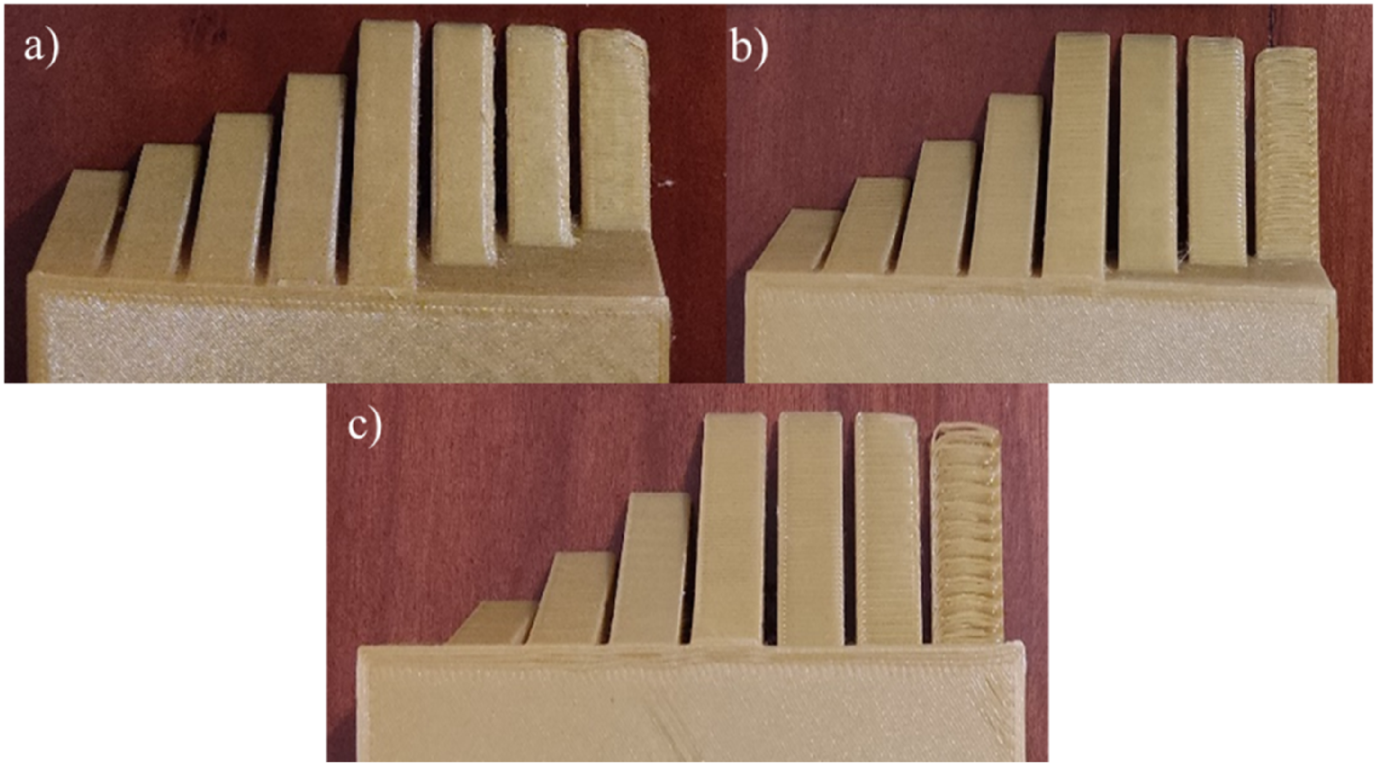
By printing this sample at different layer heights, it was possible to observe the effect of the layer height on the maximum print angle and thus define the limits for the print angle. At 0.1 mm, almost all the slopes showed very good results, except for the 70° and 80° slopes, which have a slight defect on the right side of the width in the ramp area. The maximum pressure angle was 80°. On the other hand, for 0.2 mm, only the 80° pitch had some defects in the formation of the ramp, and the maximum angle was 70°, as well as for 0.3 mm, which only had defects in the formation of the 80° ramp.
Considering that the maximum planar printing angle was around 70°–80°, depending on the selected layer height, an optimization study was conducted to increase this value to enable the printing of a new range of geometries without supports. To verify and quantify this parameter, several “T-specimen” models were designed and printed (Figure 20). (a) Requests originated by material extrusion in the printing process of a suspended geometry, (b) T-specimen to determine the maximum printing length without supports, and (c) Bottom view of the printed T-specimen.
After analysing the various specimens manufactured to optimise the maximum printing angle, it was determined that it would be possible to increase the maximum printing angle to 90° using the non-planar printing technique. Increasing the printing angle enables an increase in the number of geometries that can be printed without supports, resulting in material savings.
Having confirmed the possibility of increasing the maximum printing angle, the maximum length that can be printed without supports could be analysed. This analysis revealed that as the length of the suspended impression increases, a bending moment forms and increases on the edge on which the suspended impression is being made (Figure 20(a)). In this analysis, it was found that, for a 20 × 20 mm2 specimen base, the maximum printing length without supports is 30 mm (Figure 20(b) and (c), since all specimens with a length greater than 30 mm became detached from the printing bed during printing, the resulting bending moment caused by the extrusion force, which was always constant, made it impossible to continue printing the desired object, necessitating a stop.
The ability to print objects without using supports enables this printing space, which would otherwise be occupied by support bases, to be used to manufacture a larger quantity of objects. Another objective of this study is to verify whether the non-planar printing technique can optimise the printing space.
As previously mentioned, the FDM additive manufacturing process offers several benefits for large-scale production. However, this optimisation could be useful if it is necessary to maximise the area and reduce printing cycle times. As the printer does not require an operator during printing, optimisation could enable longer production cycles and allow the operator to perform other tasks.
Surface qualification: Roughness measurements
Roughness tests on the ‘Triangular’ specimens showed how printing parameters affect surface quality. Increasing the extrusion width was found to result in variations in part topology. In parts with a smaller extrusion width, the roughness profiles showed small protrusions caused by the position of the extrusion nozzle and an excess of material. As the extrusion width increased, these protrusions decreased, but gaps appeared between the extrusion paths.
It was concluded that keeping the nozzle parallel to the print bed at all times can lead to incorrect and unstable print path formation due to the extruded material being dragged.
Following a visual analysis to identify the most relevant characteristics of the printed ‘triangular’ specimens, several roughness tests were conducted on the top surfaces to provide a detailed analysis of the surface quality of the printed parts.
The roughness test results were organised into roughness profile tables and graphs to allow better interpretation and comparison of the data. Furthermore, the average roughness (Ra) and total height (Rt) were calculated from the three roughness profiles obtained from each specimen. To ensure the accuracy of these averages, the relative standard deviation (RSD) was also determined for each one.
Values obtained in the roughness tests of the planar and non-planar “Triangular” specimen.

The tests indicated that roughness generally increases with the inclination of the surface to be printed. This characteristic may be associated with the strength of the specimens, since a rougher surface increases the likelihood of defects.
It is important to note in Table 5 that roughness measurements could not be performed on the specimen at a 30° inclination. This was because the high surface roughness caused the measuring device to exceed its measurement range on several attempts, resulting in successive interruptions to the tests.
Based on this, the non-planar technique offers many advantages in the printing process. As observed by Alsharhan et al., 31 it can influence the mechanical characteristics of the main specimens. When comparing the planar and non-planar processes, the authors found that non-planar deposition resulted in higher stiffness and peak load, as well as sudden structural failure. In contrast, the planar process resulted in higher compliance and progressive failure. Singamneni et al. 19 observed a 40% increase in maximum compressive load for the non-planar specimen using three-point flexure tests when comparing the non-planar process with the conventional one. This is because the non-planar specimen exhibited ductile fracture with significant plastic deformation. Similarly, Huang and Singamneni 27 obtained a 51% increase in compressive load for a non-planar specimen.
Another relevant aspect of non-planar printing from a sustainability perspective is its potential to improve the environmental footprint. For example, Cendrero et al. 32 found that the non-planar technique had several advantages over the conventional process, thanks to its versatility and quality. It also uses quick reusable tools to replace support meshes, reducing waste and expensive processing. Therefore, the result achieved with the non-planar method can be said to provide precise, economical production that meets the requirements of a given application.
Conclusions
This study aimed to examine the key features and potential applications of non-planar printing in three-axis FDM printers, with a focus on enhancing the printer design.
After analysing the non-planar printing methodology, it was found that, to implement it, the print head would require ample space around it to allow the part to be printed without colliding with the print head. It was then determined that optimising the planar print height and angle would allow non-planar printing to be performed with fewer limitations, as the print head housing limited its implementation.
To increase the capacity of these two parameters, the print head components were repositioned, and a new housing was manufactured. This enabled the non-planar printing angle to be optimised from around 6°, the maximum angle possible with the original printer housing, to around 30°. The non-planar print height could also be increased from 22.6 mm to 50 mm.
Future work could involve printing samples using planar and non-planar techniques, comparing their characteristics and mechanical properties, and performing a print using both techniques in a practical application.
Footnotes
Acknowledgements
The authors thank the Polytechnic Institute of Porto - Instituto Superior de Engenharia do Porto - IPP/ISEP for the infrastructure offered for the development of this project, and Centro Paula Souza - College of Technology São José dos Campos, Professor Jessen Vidal, FATEC/SJC- Brazil, for supporting the internationalisation of the RJI project in partnership with IPP-ISEP- Porto. Portugal.
Author contributions
All authors contributed to the study conception and design. Material preparation, data collection and analysis were performed by João Paulo Marques Magalhães Costa, Arnaldo Manuel Guedes Pinto, and Francisco José Gomes da Silva. The first draft of the manuscript was written by Naiara Poli Veneziani Sebbe and Rita de Cássia Mendonça Sales-Contini, The first draft was reviewed by André Filipe Varandas Pedroso, Rafael Resende Lucas, and all authors commented on previous versions of the manuscript. All authors read and approved the final manuscript.
Funding
The authors received no financial support for the research, authorship, and/or publication of this article.
Declaration of conflicting interests
The authors declared no potential conflicts of interest with respect to the research, authorship, and/or publication of this article.
Data Availability Statement
The authors declare that the data supporting the findings of this study are available within the paper.