
Abstract
Well dispersed polyethylene (PE) nanocomposites were developed. Montmorillonite (MMT) as aluminosilicate clay layers was modified using organic silanes of different side chains. The MMT was grafted using 3-(trimethoxysilyl)propylamine, N-[3-(trimethoxysilyl)propyl]ethylenediamine, and trimethoxyvinylsilane. The modification process of MMT using organic different silanes was elucidated using microscopic, thermogravimetric, spectroscopic, and X-ray diffraction tools. Then, the developed organoclays were dispersed uniformly in PE matrix producing well exfoliated and dispersed polymer nanocomposites. The mass loadings of dispersed organoclay were varied and the impact of organic silane structure was studied. Thermal stability and flammability properties of the developed polymer nanocomposites were evaluated. The peak heat release rate and average heat release rate were reduced by 48% and 61%, respectively compared to virgin polymer. Also, the average mass loss rate was significantly reduced by 50%. This is in addition to reduction in emission of carbon monoxide (CO) and carbon dioxide (CO2) by 45% and 56%, respectively. The effect of side chain of organosilane on the performance of modified clay layers was studied. The toxicity of gases evolved during combustion process of PE and their polymer nanocomposites were evaluated using Fourier transform infrared connected to cone calorimeter. Additionally, the influence of organic silane on the pyrolysis and toxic gases emission was further studied.
Introduction
Thermoplastic polymers have been involved in various applications, however, their high flammability hazard and inferior thermal stability represent a defect in their use in some applications. 1 Polyethylene (PE) is one of the widely used polymers due to their excellent properties such as good chemical resistance, low weight, cost, and good processability.2,3 Hence, due to its unique properties and facile processability, PE is used in various domestic and industrial applications.4–6 Nevertheless, its low thermal stability and high flammability attributed to high fire hazard. 2 The incorporation of clay sheets into thermoplastic polymers yielding polymer nanocomposites of promising mechanical, thermal, and fire retardancy properties which are demand in various industrial applications, this is in addition to its cost-effective processing.7–12 Furthermore, the well dispersion of clay layers in polymer matrix is very crucial for obtaining good interaction between polymer chains and clay layers, and in turn good performance of polymer nanocomposites.13,14 The good dispersion of clay layers can be processed through the intercalation and exfoliation of clay layers into polymer chains. However, to facilitate the intercalation and exfoliation of clay layers into organic polymer matrix, the clay layers have to be modified with organic moiety to increase the distance between clay layers and to enhance clay layers compatibility with organic polymer chains.2,15 On the other hand, montmorillonite (MMT) is one of the extensively used clay layers due to its properties and facile modification process with organic compounds.16–19 To this end, chemical modification of MMT through treatment with organic molecules and inserting between clay layers, hence, increasing the interlayer spaces which then promote the inclusion of polymer chains into MMT interlayer distance spaces.17,18 There are various methods have been used for organic modification of MMT, however, the mainly used one is cation exchange with ammonium salts.20–22 Nevertheless, this process has some drawbacks such as low thermal stability of some ammonium compounds and inefficient interaction between clay and polymer chains. 20 Therefore, the scientists found that the reaction of silane coupling agent with silanol groups situated on clay edges, internal and external surfaces, provides a good alternative approach for MMT modification.20,23–26 Then, there are various alkoxysilane compounds have been used in the modification of MMT.27–29 There are a variety of nanomaterials have been used as flame retardants for thermoplastic polymers.1,30–32 Interestingly, the silane-modified MMT as a flame-retardant fillers for thermoplastic polymers provides a cost-effective and facile approach in terms of flame retardancy and mechanical properties efficiency compared to other flame-retardant fillers such as carbon nanotubes, 33 layered hydroxides, 34 unmodified MMT, 35 and conventional phosphorous compounds. 36 Polymer nanocomposites based on organic modified layered silicate attracted attentions in improving the flame retardancy and mechanical properties of their polymer nanocomposites.37,38 In our recent studies, flame retardancy properties of various nanoscale materials have been studied.30–32,39,40 Therefore, the smart modification of clay layers played a crucial role for their dispersion and interaction with polymer chains. Hence, the proper selection of organic modifier for MMT layers modification has a significant impact in this process for achieving superior flame retardancy and mechanical properties of the polymer nanocomposites. It has been previously reported that the clay layers forms thermal shielding barrier which retard the heat and mass transfer. 41 In this study, the MMT layers have been modified using different organic modifier with different side chains: 3-(trimethoxysilyl)propylamine, N-[3-(trimethoxysilyl)propyl]ethylenediamine, and trimethoxyvinylsilane. The efficiency of modification and structure of modified MMT have been studied. The modified MMT have been dispersed in PE forming polymer nanocomposites. Mass loadings of modified MMT have been varied and optimized. The dispersion of modified MMT in PE matrix has been investigated. The flammability, toxic gases emission, and thermal properties of the polymer nanocomposites have been studied.
Experiment
Materials
Linear low-density polyethylene was supplied from Sabic Company (Saudi Arabia). The MMT K10 was bought from Sigma-Aldrich. 3-(Trimethoxysilyl)propylamine and trimethoxyvinylsilane with densities of 1.013 g cm−3 and 0.968 g cm−3, respectively, were provided by Merck (Germany). N-[3-(Trimethoxysilyl)propyl]ethylenediamine with density of 1.028 g cm−3 was bought from Sigma-Aldrich (USA). Ethanol was purchased from El Nasr Pharmaceutical Chemicals Co. (Egypt).
Modification of MMT
The modification process of MMT was developed based on the previous reports.42,43 One gram of MMT was dispersed in 20 mL solution of ethanol/water (75/25 vol.%, respectively) and magnetically stirred at 80°C. Then, 1.0 g of silane compounds (3-(trimethoxysilyl)propylamine, N-[3-(trimethoxysilyl)propyl]ethylenediamine, and trimethoxyvinylsilane) was added individually to the clay dispersion. The previous dispersions were magnetically stirred for 24 h at 80°C. Afterward, modified MMT was filtered and dried at 100°C. Finally, the modified MMT was coded as MMT-S1, MMT-S2, and MMT-S3 based on silane compounds 3-(trimethoxysilyl)propylamine, N-[3-(trimethoxysilyl)propyl]ethylenediamine, and trimethoxyvinylsilane, respectively.
Synthesis of PE-MMT, PE-MMT-S1, PE-MMT-S2, and PE-MMT-S3 nanocomposites
The PE nanocomposites were prepared using melt mixing method by lab-scale twin-screw extruder (NCMT-20, Neoplast Company, Ahmedabad, Gujarat, India). PE nanocomposites composition was prepared based on the Table 1. However, the extruder processing revolutions per minute was 30 and zone 1, 2, and 3 temperatures were 168°C, 170°C, and 170°C, respectively. Afterward, the samples were molded at 180°C for 10 min at 100 tons.
Composition of PE and their nanocomposites.
PE: polyethylene; MMT: montmorillonite; LLDP: linear low-density polyethylene.
Characterization
Fourier transform infrared spectroscopic analysis was performed using a Nicolet 380 spectrophotometer (Thermo Fisher Scientific, Waltham, Massachusetts, USA), over the spectral range of 4000–400 cm−1. Thermogravimetric analysis (TGA) was carried out using DTG-60 simultaneous (Shimadzu) (DTA-TG) from room temperature to 750°C under nitrogen flow. X-ray diffractometric (XRD) measurements were performed using copper (Cu) as the source for generating X-rays with a Kα1Cu wavelength = 1.54060 Å, and a voltage of 45 kV and current of 35 mA. Scanning electron microscopic (SEM) images were taken using (Quanta FEG250, Thermo Fisher Scientific, Waltham, Massachusetts, USA). The flammability properties of virgin PE and their nanocomposites were tested using cone calorimeter (Fire Testing Technology, West Sussex, UK) according to ISO 5660-1. 44 The significant fire parameters considered were time to ignition (tign), total heat release (THR), average heat release rate (AHRR), peak heat release rate (PHRR), average effective heat of combustion (AEHC), and average mass loss rate (AMLR). This is in addition to evolved CO and CO2.
Results and discussion
Structural characterization of modified MMT
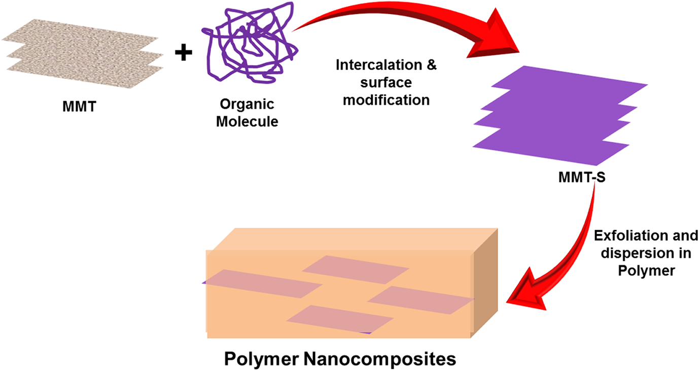
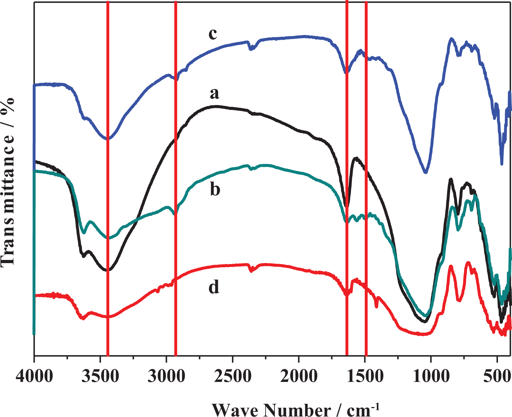
The MMT was modified with three orgnosilanes compounds with different side chains as shown in Figure 1. The structure of parent and functionalized MMT was characterized using FTIR spectroscopy. Figure 2(a) shows the characteristic absorption bands of pristine MMT. The absorption band situated at 3632 cm−1 was corresponding to stretching vibrations of O–H groups associated to octahedral cations which are characteristic to MMT.45–48 However, the absorption bands observed at 3444 cm−1and 1635 cm−1 were assigned to O–H stretching vibration and bending vibration correlated with the existing of interlayer water, respectively.43,45–48 Furthermore, the strong absorption band appeared at 1063 cm−1 was assigned to the stretching vibration of Si–O of tetrahedral layer and the small band observed at 917 cm−1 was due to the bending modes of AI–OH–AI.45,47–49 Interestingly, the band positioned at 800 cm−1 was corresponding to the Si–O–Si vibrations. 50 Figure 2(b) shows the FTIR spectrum of MMT-S1, which reflected the characteristic absorption bands of MMT and proves the grafting of MMT with organosilane S1. The absorption band observed at 2928 cm−1 was assigned to C–H stretching vibration of CH2 and one appeared at 2853 cm−1 was assigned to C–H asymmetric vibrations of CH2.45,51 Moreover, the band detected at 1559 cm−1 was assigned to bending vibration of NH2. However, the band situated at 1475 cm−1 was attributed to bending vibration of CH2. 52 On the other hand, the FTIR spectrum of MMT-S2 (Figure 2(c)) displayed new several bands that proves the grafting of MMT with N-[3-(trimethoxysilyl)propyl]ethylenediamine. Hence, the absorption bands detected at 2928 cm−1 and 2844 cm−1 were attributed to C–H asymmetric and symmetric stretching vibrations of –CH2, respectively. 52 Similarly, the FTIR spectrum of MMT-S3 (Figure 2(d)) confirms the successful grafting process of MMT with the trimethoxyvinylsilane organosilane. Furthermore, the absorption band appeared at 2956 cm−1 was corresponding to C–H symmetric stretching vibrations of CH2. 52 On the other hand, the TGA of the MMT and its functionalized ones are depicted in Figure 3. Figure 3(a) shows the thermogram of virgin MMT, whereas the first mass loss below 150°C was attributed to the trapped moisture. However, the second mass loss started at 400°C was assigned to the dehydroxylation of MMT.45,53 Figure 3(b) shows the thermogram of MMT-S1 which demonstrated two mass loss steps. The first one detected below 150°C was attributed to trapped water. The second one in the temperature range of 200–700°C was assigned to the decomposition of grafted organosilane chains and dehydroxylation of MMT.45,53 Furthermore, the thermogram of MMT-S2 (Figure 3(c)) reflects similar thermal behavior as in MMT-S1 with two mass loss steps in the same temperature range. However, the mass loss in the second step shows higher value than in MMT-S1. This confirmed the functionalization of MMT with organosilanes and the tendency of functionalization was affected by structure of organosilane compounds. It is important to note that the first mass loss (trapped moisture) in functionalized MMT was lower than unmodified MMT. This was due to the hydrophobic nature of functionalized MMT, hence organic species replaced water in interlayer spaces of MMT.45,54 In contrast, the TGA curve of MMT-S3 shown in Figure 3(d) reflects different thermal behavior than MMT-S1 and MMT-S2, whereas the first and second mass losses were reduced compared to MMT-S1 and MMT-S2. This could be attributed to the grafted organosilane reduced the physisorbed water as indicated above and also reduce the extent of dehydroxylation of MMT itself.
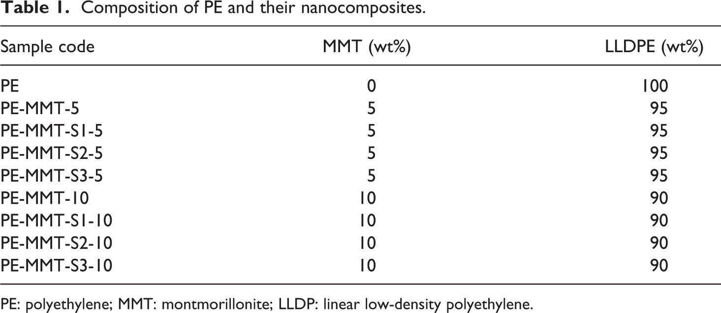
Schematic diagram representing the functionalization of MMT and their dispersion in polymer matrix forming dispersed polymer nanocomposites. MMT: montmorillonite.
FTIR spectra of (a) pristine MMT, (b) MTT-S1, (c) MMT-S2, and (d) MMT-S3. FTIR: Fourier transform infrared; MMT: montmorillonite.
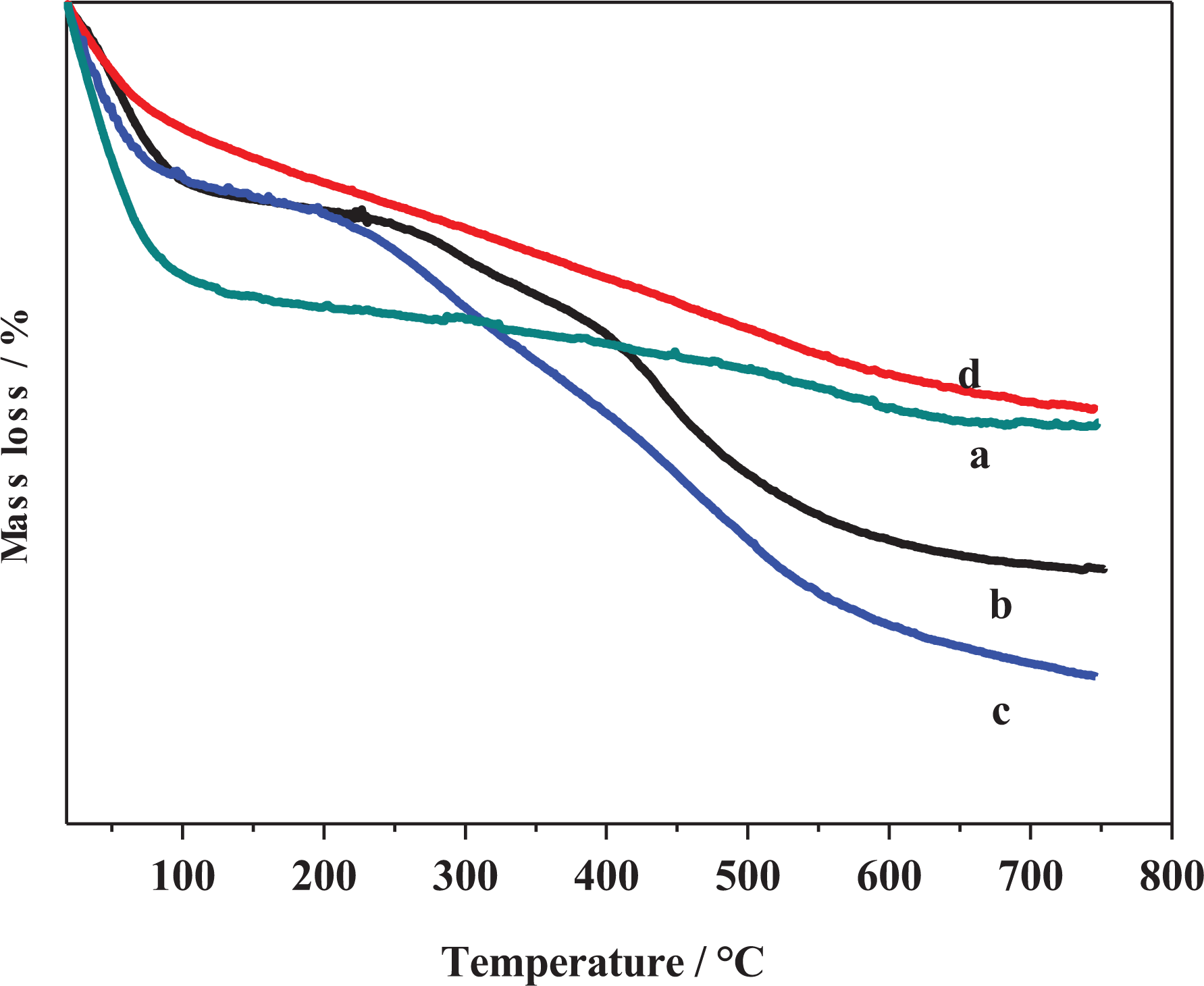
TGA curves of (a) pristine MMT, (b) MTT-S1, (c) MMT-S2, and (d) MMT-S3. TGA: thermogravimetric analysis; MMT: montmorillonite.
Furthermore, the functionalization process of MMT using organosilanes was elucidated using XRD measurements. Figure 4 shows the XRD pattern of MMT and its functionalized forms. The XRD of MMT represents peak at 2θ equal to 8.9o which assigned to d001 basal spacing of MMT (Figure 4(a)).45,52,55 The XRD of the functionalized forms of MMT-S1, MMT-S2, and MMT-S3 exhibited same peak of basal spacing of MMT. However, slight shift to lower 2θ (Figure 4(b) to (d)) was observed. This shift was attributed to slight intercalation of organosilanes inside interlayer spaces of MMT. Moreover, new broad band at 2θ equal to 5.5o was observed in MMT-S3 which might be due to the occurrence of slight intercalation. This affirms that organosilanes grafted on MMT was mainly on the surface of MMT and slight intercalation inside interlayer distances has been taken place.
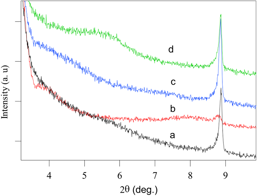
XRD pattern of (a) MMT, (b) MMT-S1, (c) MMT-S2, and (d) MMT-S3. XRD: X-ray diffractometer; MMT: montmorillonite.
On the other hand, the surface morphology of MMT and its functionalized composites MMT-S1, MMT-S2, and MMT-S3 was investigated using microscopic techniques. Figure 5(a) shows the SEM image of virgin MMT which clearly indicates the roughness of clay structure without coating its surface. However, when MMT was functionalized with S1, the surface of MMT was coated with S1 molecules and smooth surface was observed for MMT-S1 surface as shown in Figure 5(b). Similar surface morphology was also observed for MMT-S2 and MMT-S3 as shown in Figure 5(c) and (d).
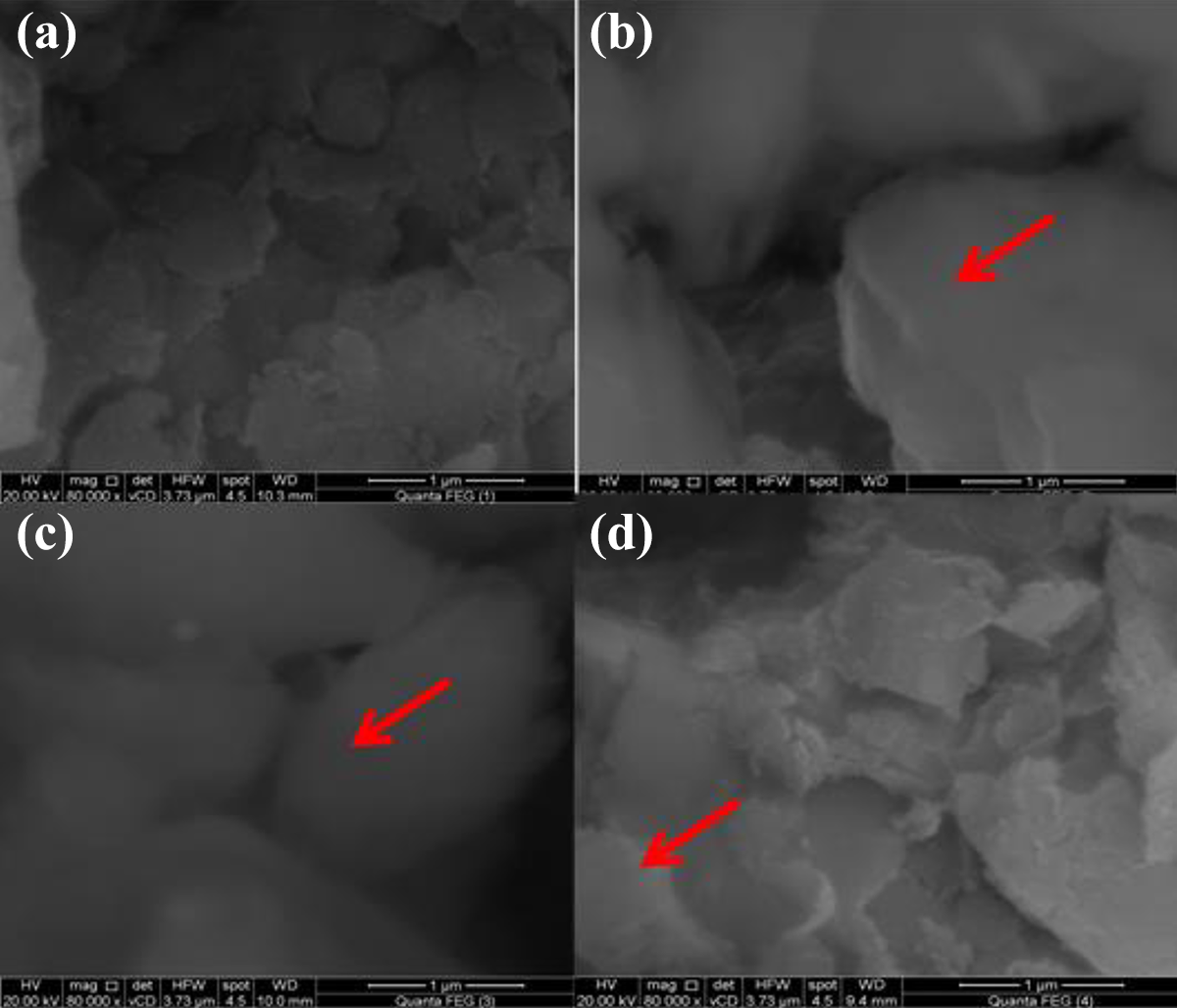
SEM images of (a) MMT, (b) MMT-S1, (c) MMT-S2, and (d) MMT-S3. SEM: scanning electron microscopy; MMT: montmorillonite.
Characterization of polymer nanocomposites
PE nanocomposites were prepared using melt blending method as shown in Figure 1. As, MMT-S1, MMT-S2, and MMT-S3 were incorporated and dispersed in PE in two mass loadings (5 wt% and 10 wt%) forming PE-MMT-S1, PE-MMT-S2, and PE-MMT-S3 in addition to PE-MMT. The efficiency of dispersion and exfoliation of modified MMT on polymer matrix were studied using XRD and SEM. Figure 6 shows the XRD patterns of virgin MMT and its PE-MMT-5 and PE-MMT-10 nanocomposites. Since, MMT had strong peak at 2θ of 8.9o, corresponding to d001 basal spacing of 0.99 nm. However, this peak was almost disappeared in the PE-MMT-5 and PE-MMT-10 nanocomposites. This is attributed to exfoliation of MMT layers in polymer matrix in case of PE-MMT-5 and partially exfoliated in PE-MMT-10 nanocomposites (Figure 6). However, the exfoliated layers were not well dispersed in polymer and they aggregated as discussed below. Furthermore, the XRD patterns of the grafted MMT-S1 and its polymer nanocomposites PE-MMT-S1-5 and PE-MMT-S1-10 are shown in Figure 7(a). These patterns clearly indicated that the intensity of MMT peak of d001 was significantly reduced and broadness of the peak was observed in both polymer nanocomposites which affirm the exfoliation of MMT-S1 in polymer matrix.56–58 However, in case of PE-MMT-S2-5, the intensity of d001 peak was reduced but still observed which support partial exfoliation as depicted in Figure 7(b). Further increase in mass loading of MMT-S2 to 10 wt% in PE attributed to the disappearance of d001 peak as result of exfoliation of MMT-S2 layers in polymer matrix (Figure 7(b)). Interestingly, in case of PE-MMT-S3-5 and PE-MMT-S3-10 nanocomposites complete disappearance of d001 peak was observed, which corroborated the loosing of its ordered structure and confirmed full exfoliation and dispersion of MMT-S3 in polymer (Figure 7(c)). Hence, as indicated above, the structure of organic silane played an important role in exfoliation and dispersion of MMT layers in polymer. The dispersion of organoclay in PE matrix was further investigated using SEM and transmission electron microscopy (TEM) images of the polymer nanocomposites. Figure 8(a) shows the morphology of the PE-MMT-5 which reflected the poor dispersion and aggregation of MMT layers in PE matrix as indicated by arrows. However, well dispersion for exfoliated MMT-S1-5 layers was observed as shown in Figure 8(b). This uniform dispersion of exfoliated organoclay layers was further observed in PE-MMT-S2-5 and PE-MMT-S3-5 nanocomposites as depicted in Figure 8(c) and (d). Interestingly, in high mass loadings of MMT-S3 in PE-MMT-S3-10, good dispersion of exfoliated MMT-S3 layers was also obtained without noticeable aggregation as indicated by arrows in Figure 8(e). The exfoliation of organoclay layers were further corroborated by TEM images of PE-MMT-S1-5, PE-MMT-S2-5, and PE-MMT-S3-5. Hence, Figure 9 shows good exfoliation of organoclays and excellent dispersion of exfoliated organoclay layers in PE-MMT-S1-5 nanocomposite as indicated by arrow (Figure 9(a)).
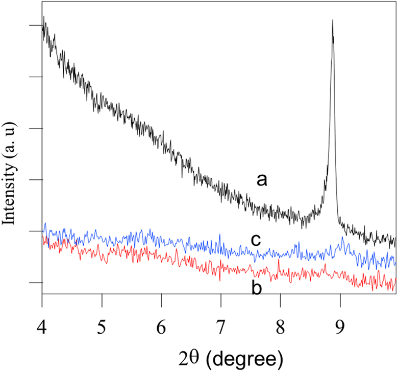
XRD pattern of (a) MMT, (b) PE-MMT-5, and (c) PE-MMT-10. XRD: X-ray diffractometer; PE: polyethylene; MMT: montmorillonite.
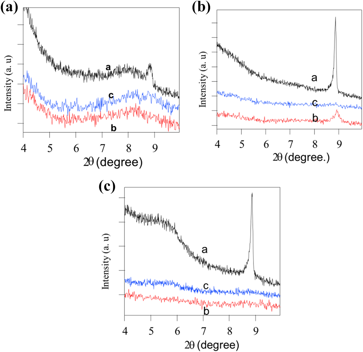
XRD pattern of (a) MMT-S1 (a), PE-MMT-S1-5 (b), PE-MMT-S1-10 (c); (b) MMT-S2 (a), PE-MMT-S2-5 (b), PE-MMT-S2-10 (c); and (c) MMT-S3 (a), PE-MMT-S3-5 (b), PE-MMT-S3-10 (c). XRD: X-ray diffractometer; PE: polyethylene; MMT: montmorillonite.
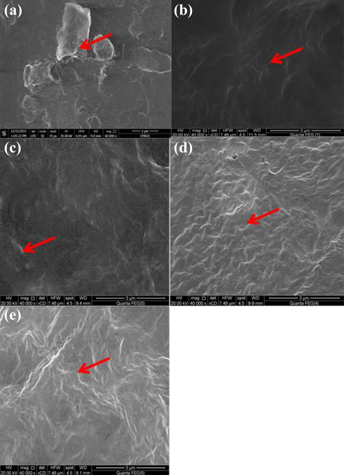
SEM images of (a) PE-MMT-5, (b) PE-MMT-S1-5, (c) PE-MMT-S2-5, (d) PE-MMT-S3-5, and (e) PE-MMT-S3-10. SEM: scanning electron microscopy; PE: polyethylene; MMT: montmorillonite.
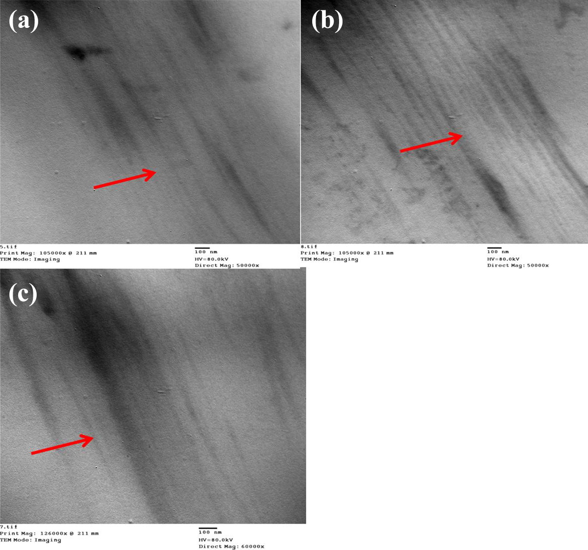
TEM images of (a) PE-MMT-S1-5, (b) PE-MMT-S2-5, and (c) PE-MMT-S3-5. TEM: transmission electron microscopy; PE: polyethylene; MMT: montmorillonite.
Thermal properties of polymer nanocomposites
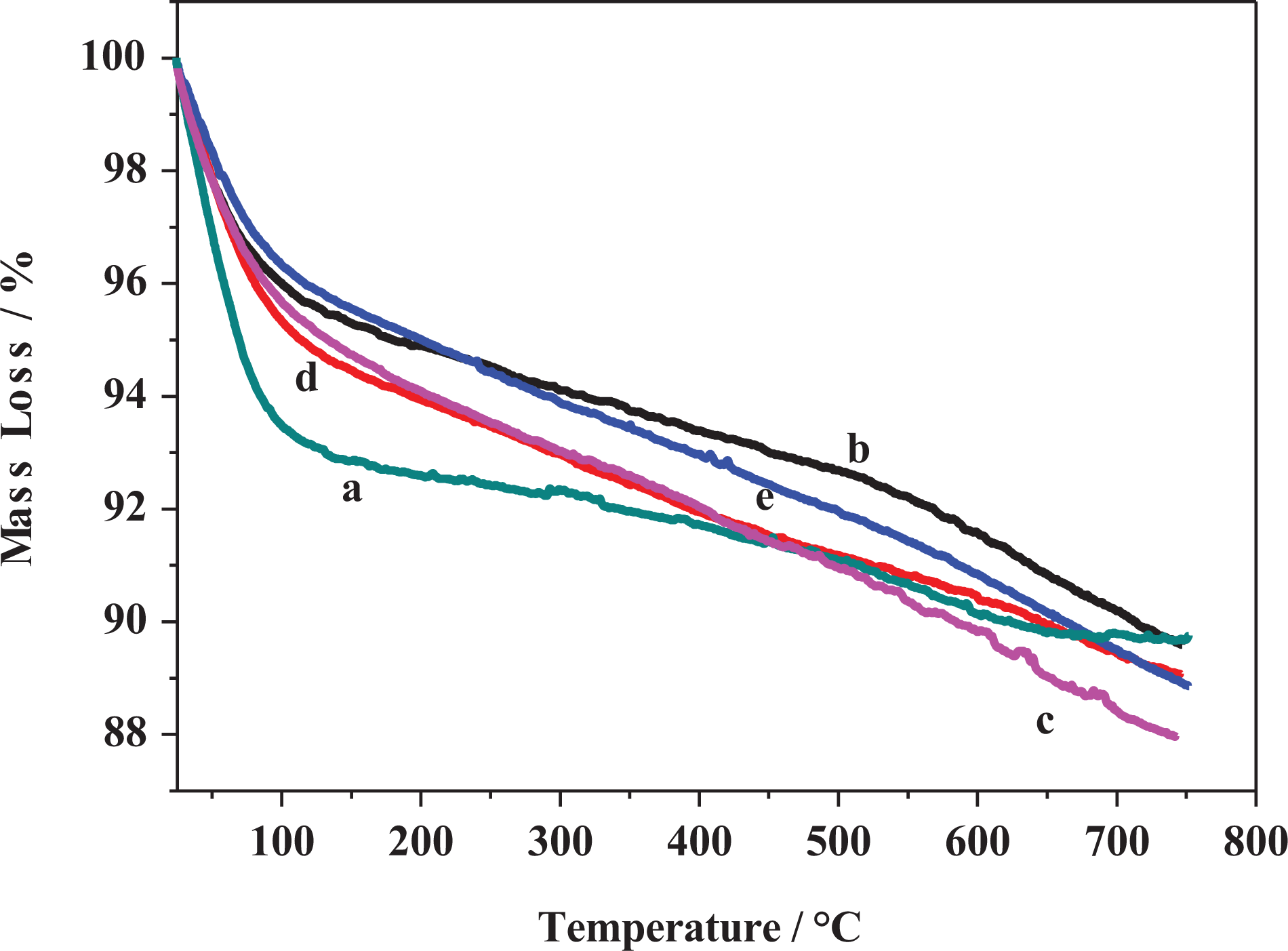
The thermal properties of PE and its polymer nanocomposites were evaluated using TGA. Figure 10(a) shows the TGA thermogram of PE which decomposed in only one step started at 400°C leaving 1.3 wt% char yield. The thermogram of PE-MMT-5 as depicted in Figure 10(b) shows one decomposition step similar to PE, but with earlier decomposition temperature of 300°C associated with char yield of 4 wt%. This earlier decomposition temperature of PE-MMT-5 was attributed to the fact that clay layers catalyzed the degradation of polymer–clay nanocomposites.59,60 Interestingly, the thermal behavior of PE-MMT-S1-5 and PE-MMT-S2-5 was found to be similar to PE but with different char yields of 5.6 wt% and 4.8 wt%, respectively (Figure 10(c) and (d)). Figure 10(e) exhibits the thermogram of PE-MMT-S3-5 which showed lower decomposition temperature than other polymer nanocomposites having char yield of 3.9 wt%. It was observed inferior of thermal stability of PE-MMT-S nanocomposites than PE itself. This was attributed to the phenomena of at high temperature free silane formed free radicals and initiating polymer chains degradation. 61 However, the difference in thermal behavior between PE-MMT-S1 and PE-MMT-S2 from one side and PE-MMT-S3 from other side reflects the role of side chains of organosilane. Thus, attributed to positive influence in the thermal behavior and trigger polymer chains for forming char barrier which was optimum in case of PE-MMT-S1-5 giving rise of 5.6 wt% char residue.
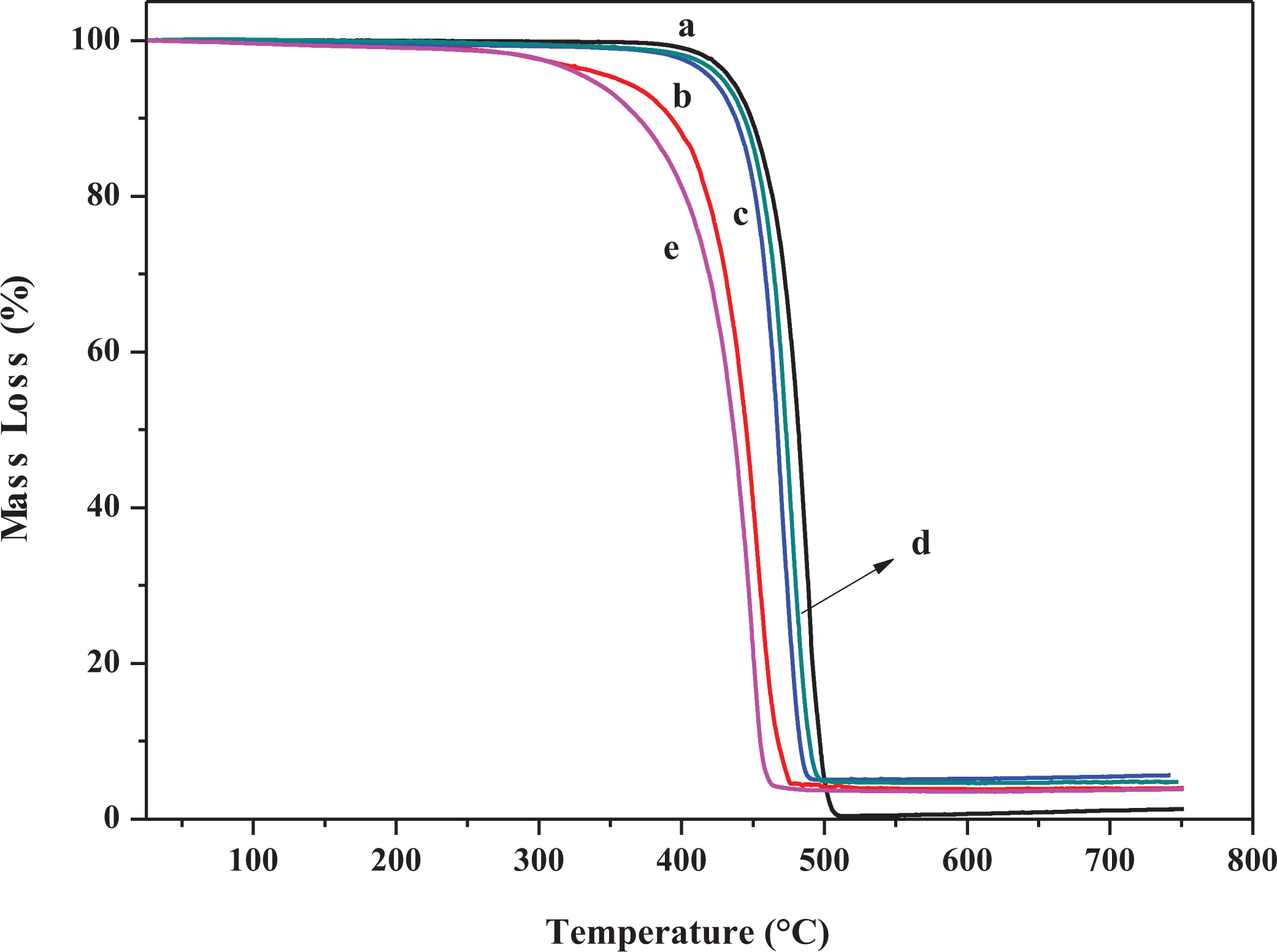
TGA curves of (a) PE, (b) PE-MMT-5, (c) PE-MMT-S1-5, (d) PE-MMT-S2-5, and (e) PE-MMT-S3-5. TGA: thermogravimetric analysis; PE: polyethylene; MMT: montmorillonite.
Flammability properties of polymer nanocomposites
The flammability properties of pure PE and its polymer nanocomposites were investigated using cone calorimeter test. The cone calorimetric data were tabulated in Tables 2 and 3. The heat release rate (HRR) curves for PE and its PE-clay nanocomposites are shown in Figures 11 and 12. The PE ignited after 94 s and burned directly giving rise a PHRR of 1395 kW m−2 with THR of 162 MJ m−2. The AHRR was found to be 790 kW m−2. However, when MMT was incorporated in the PE matrix in PE-MMT-5 nanocomposite, the PHRR was reduced to 1026 kW m−2, in conjunction with reduction in AHRR by 44% as presented in Table 2. But the THR altered change compared to PE. Further increase in mass loading of MMT in PE (PE-MMT-10) attributed to further reduction in PHRR and reached 793 kW m−2 but the THR was little increased. Interestingly, the AEHC was reduced to 28.5 MJ kg−1 compared to 45.5 MJ kg−1 and 41 MJ kg−1 for PE-MMT-5 and PE, respectively. This flame retardancy behavior for PE-MMT was attributed to the formation of protective char barrier based on clay sheets. On the other hand, when organoclays (MMT-S) were incorporated in polymer matrix at different mass loadings, the flame retardancy effect was enhanced. Hence, the PHRR was significantly reduced to 721 kW m−2 achieving 48% reduction in PE-MMT-S1-5 nanocomposite (Table 2 and Figure 11). This positive enhancement in flame retardancy effect was stemmed from the well dispersion of exfoliated clay layers in polymer matrix affording enough char barrier which retard mass and heat transfer. This effect was further supported by the slowdown of degradation of polymer nanocomposites chains recording AMLR value of 0.025 g s−1 compared to 0.044 g s−1 for PE. However, in case of high mass loading (PE-MMT-S1-10), the PHRR had almost same value but the AHRR, THR, and AEHC were reduced compared to PE-MMT-S1-5 (Table 2 and Figure 12). In contrast, in case of PE-MMT-S2-5, the PHRR was found to be 1097 kW m−2 with AHRR of 501 kWm−2 and THR of 173 MJ m−2. The negative flame retardancy trend for PE-MMT-S2-5 compared to PE-MMT-S1-5 was also noticed in high mass loading of PE-MMT-S2-10. This is attributed to the char barrier layer formed over nanocomposite surface was initially good but its strength was not enough and then breaks down as shown in HRR curve (Figures 11 and 12). Hence, this giving rise to high PHRR and THR compared to PE-MMT-S1. Additionally, its AMLR value was higher compared to PE-MMT-S1 which detected as 0.035 g s−1 (Table 3). This behavior reflects the influence of side chain of organic silane used in MMT functionalization and its role in strengthen the char barrier formed in nanocomposites. In case of PE-MMT-S3-5, the burning behavior was almost similar to PE-MMT-S1-5 as the PHRR was reduced by 37% and AHRR and AEHC were reduced (Table 2). The PHRR, THR, AHRR, and AEHC were further reduced when mass loading increased as shown in Table 3 and Figure 12. This noticed flame retardancy effect for PE-MMT-S3-5 was further supported significant reduction of AMLR by 45% and 50% for PE-MMT-S3-5 and PE-MMT-S3-10, respectively. The flame retardancy behavior was further evaluated using rate of burning in best performing samples using UL-94 horizontal test. Therefore, the obtained results corroborated the flame retardancy behavior for modified MMT polymer nanocomposites. The reduction in the rate burning of samples was found to be 60%, 50%, and 55% for PE-MMT-S1-5, PE-MMT-S2-5, and PE-MMT-S3-5, respectively, compared to PE. Interestingly, the effect of char barrier formation upon the incorporation of MMT and its modified forms was investigated using TGA of char residues obtained after cone test. Figure 13(a) shows the thermogram of neat MMT which shows stable residue at 750°C. However, when carbonaceous char formed during the combustion of polymer nanocomposites, then new carbon char will be on clay surface residue. Since, the onset decomposition temperature of carbonaceous material is 450°C, 62 hence, the difference between carbon-based char residue weight percentage compared to MMT residue alone can be used as an indication of the ability of MMT and its silylated composites (MMT-S) to trigger PE chains to form carbon char barrier. Therefore, in case of PE-MMT-10, the carbon char residue was only 0.2 wt% of carbon-based char in addition to MMT itself residue. However, for PE-MMT-S1-10, the char formed was significantly enhanced and carbon residue was found to be 1.9 wt% (Figure 13) which is consistent with their high flame retardancy effect. The residues were found to be 0.7 wt% and 1 wt% for PE-MMT-S2-10 and PE-MMT-S3-10, respectively, which are consistent with their cone data and corroborated their respective flame retardancy effect. On the other hand, the emissions of toxic gases were also evaluated. The PE emitted average CO and CO2 of 0.022 kg kg−1 and 2.6 kg kg−1, respectively. However, when unmodified MMT was incorporated in PE-MMT-5, the emission of CO and CO2 was reduced to 0.020 kg kg−1 and 2.17 kg kg−1, respectively, and further reduced when mass loading increased. However, the emission of CO and CO2 was significantly reduced when organoclay was incorporated as presented in Table 3. In PE-MMT-S1-5, the emission of CO and CO2 were reduced by 27% and 30% compared to PE, respectively. This reflected the effect compact structure of char barrier formed which resisted the escape of gases. The CO and CO2 were also reduced in PE-MMT-S2-5 compared to PE and PE-MMT-5 as presented in Table 3. Similar gases emission reduction trend was also noticed in case of PE-MMT-S3-5 as tabulated in Table 3. Thus, the flame retardancy mechanism type of the developed nanocomposites was found to be the condensed phase one rather than gas phase.63,64 Since the protective char barrier formed over nanocomposites surface was the dominant reason for isolating the flaming zone from melting one. Thus, retard mass and heat transfer (Tables 2 and 3). Interestingly, the impact of organic modifier type was clearly observed in the strength and compactness structure of protective char layer formed. Also, its ability to trigger the polymer chains for forming char layer, hence, S1 was found to be the best modifier type in terms of flame-retardant behavior efficiency and suppression of toxic gases.
Cone calorimetric data of PE and its nanocomposites.
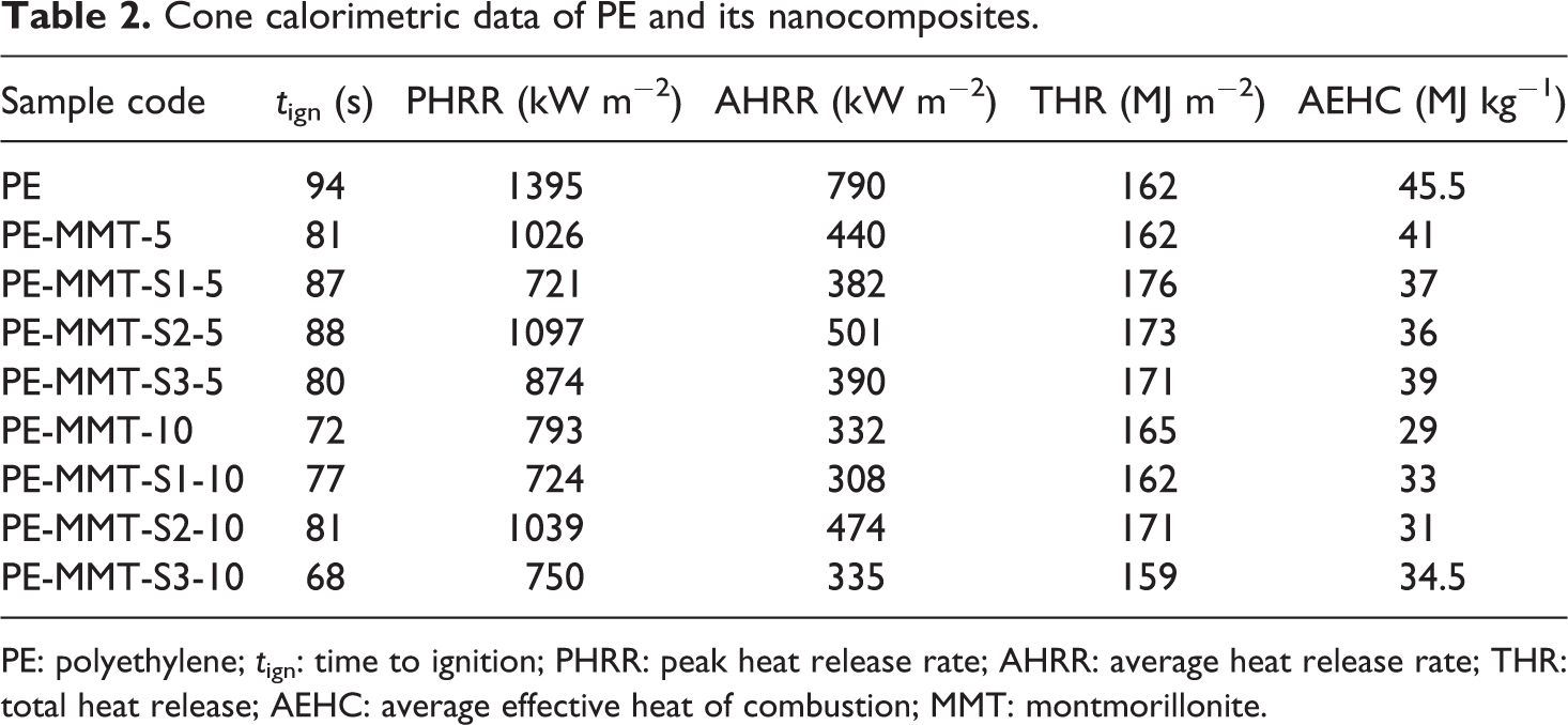
PE: polyethylene; tign: time to ignition; PHRR: peak heat release rate; AHRR: average heat release rate; THR: total heat release; AEHC: average effective heat of combustion; MMT: montmorillonite.
CO and CO2 gas emission data of PE and its nanocomposites.
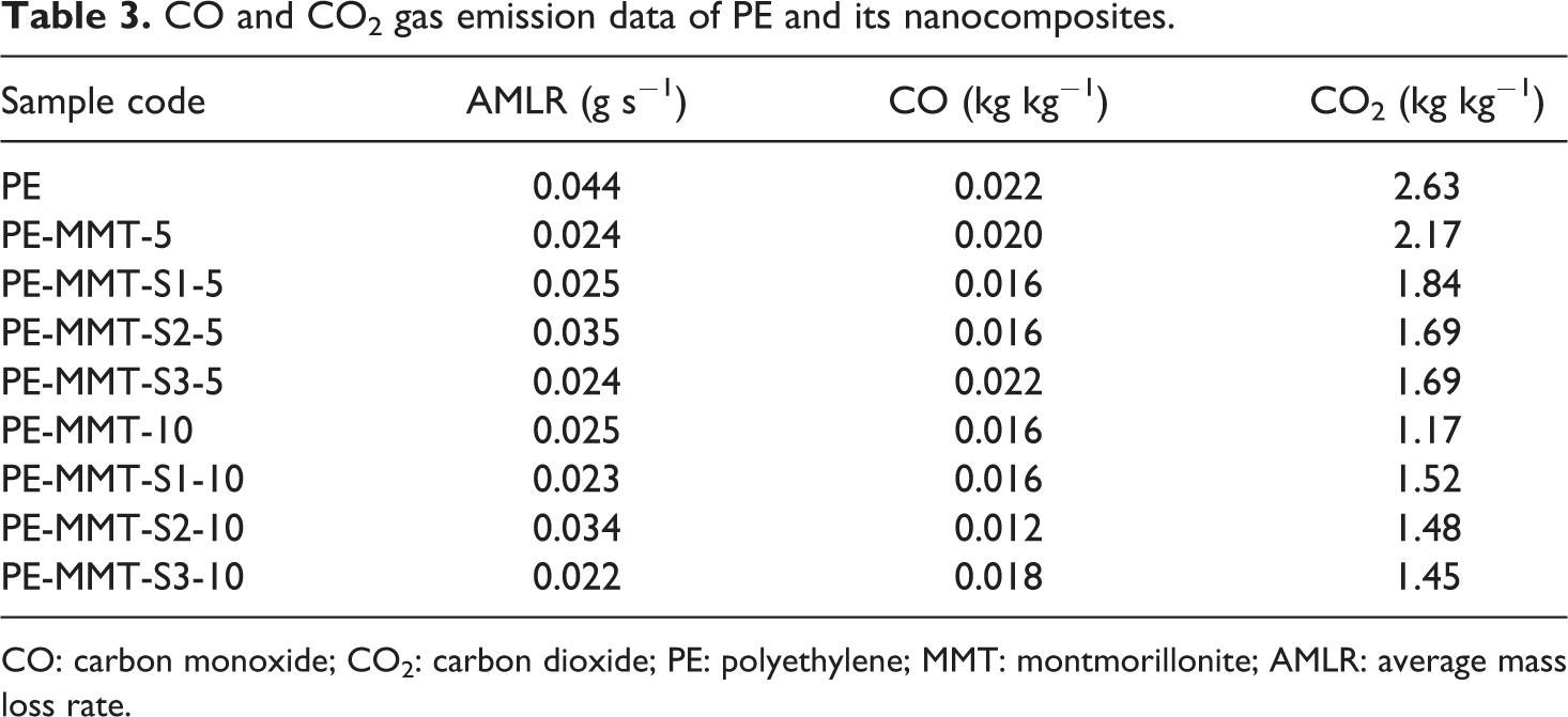
CO: carbon monoxide; CO2: carbon dioxide; PE: polyethylene; MMT: montmorillonite; AMLR: average mass loss rate.
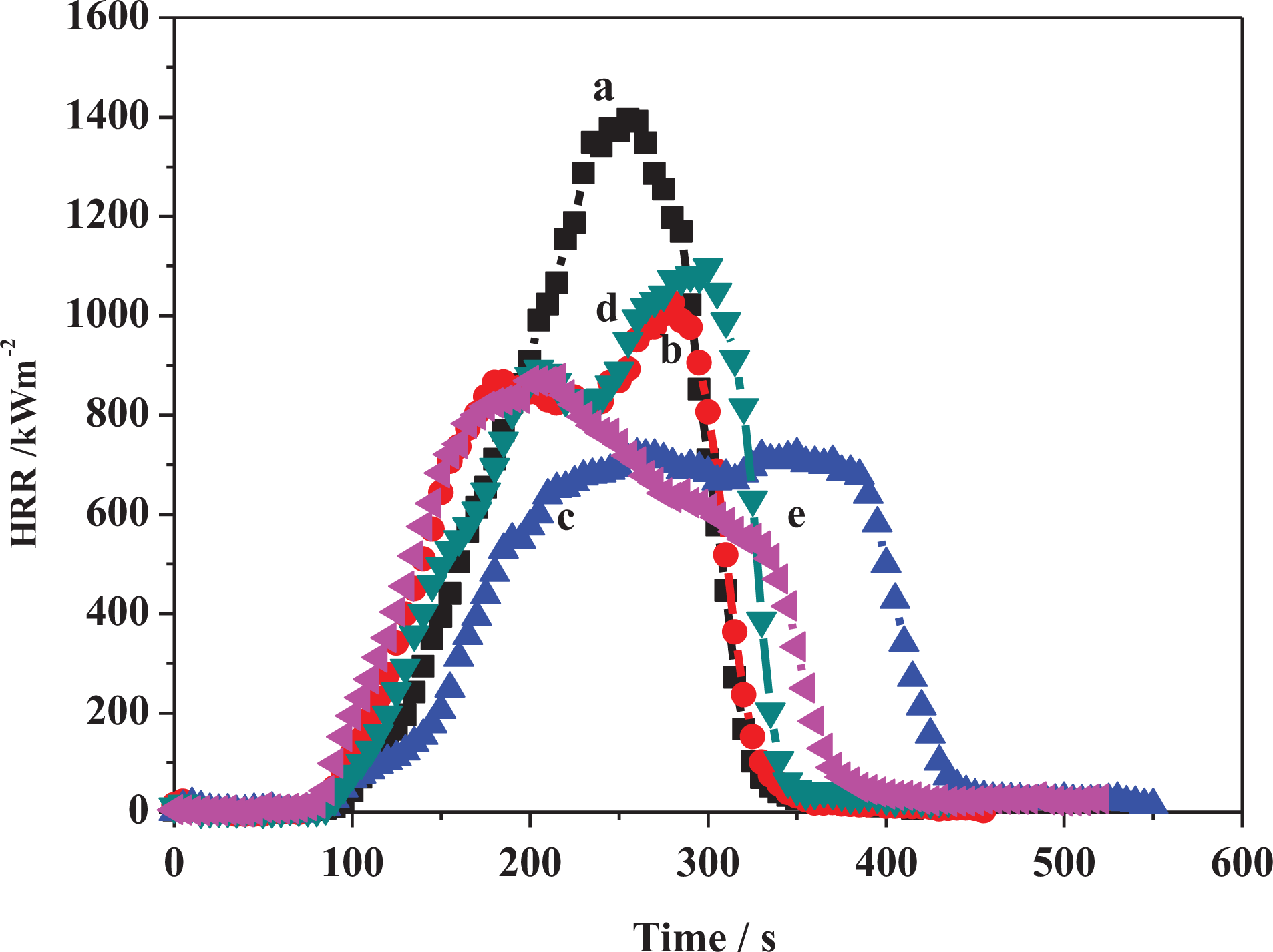
Heat release curves of (a) PE, (b) PE-MMT-5, (c) PE-MMT-S1-5, (d) PE-MMT-S2-5, and (e) PE-MMT-S3-5. PE: polyethylene; MMT: montmorillonite.
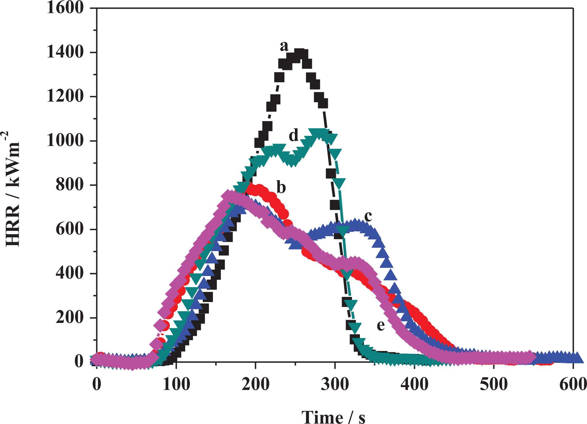
Heat release curves of (a) PE, (b) PE-MMT-10, (c) PE-MMT-S1-10, (d) PE-MMT-S2-10, and (e) PE-MMT-S3-10. PE: polyethylene; MMT: montmorillonite.
TGA curves of (a) MMT and char after cone test of (b) PE-MMT-10, (c) PE-MMT-S1-10, (d) PE-MMT-S2-10, and (e) PE-MMT-S3-10. TGA: thermogravimetric analysis; PE: polyethylene; MMT: montmorillonite.
Toxicity of combustion gases emitted
The toxicity of gases evolved during combustion of PE and their polymer nanocomposites was evaluated using FTIR connected to cone calorimeter, and this reflects real fire environment. The maximum emission of gases detected were CO2, CO, nitric oxide (NO), hydrogen cyanide (HCN), ammonia (NH3), and formaldehyde (HCHO). Figure 14 shows the maximum emission of CO2 of PE with polymer nanocomposites. The maximum emission of CO2 was significantly reduced when MMT was dispersed in polymer matrix and further reduced when modified clays were dispersed. The emission of CO was behaving same trend as it reduce when modified clays were dispersed in polymer matrix. This is due to the effective compactness structure of the char barrier which retards the escape of toxic gases (Figure 14). Furthermore, the maximum emission of NO was increased when modified clay layers were dispersed as depicted in Figure 14. However, its maximum emission was reduced in PE-MMT-S3-10 nanocomposite achieving reduction by 35% compared to PE. This is indicated that the type of organic modifier played significant role on the type and concentration of gases emitted during combustion. On contrast, when PE-MMT-S1-10 was dispersed in PE matrix the maximum emission of HCN was significantly reduced compared to other organically modified clay and PE (Figure 14). This affirms the type of organic modifier is critical and key factor of types of emitted gases. Similar trend was observed for emission of NH3 as shown in Figure 14. Interestingly, the maximum emission of HCHO was significantly reduced when modified clay was used as fillers. Whereas, the inclusion of unmodified MMT accelerates the emission of HCHO. However, when modified clay used the maximum emission was reduced significantly as shown in Figure 14. This is another evidence of the effect of type organic modifier used as it can change the polymer nanocomposite pyrolysis pathway and also the impact on the compactness of char barrier structure.
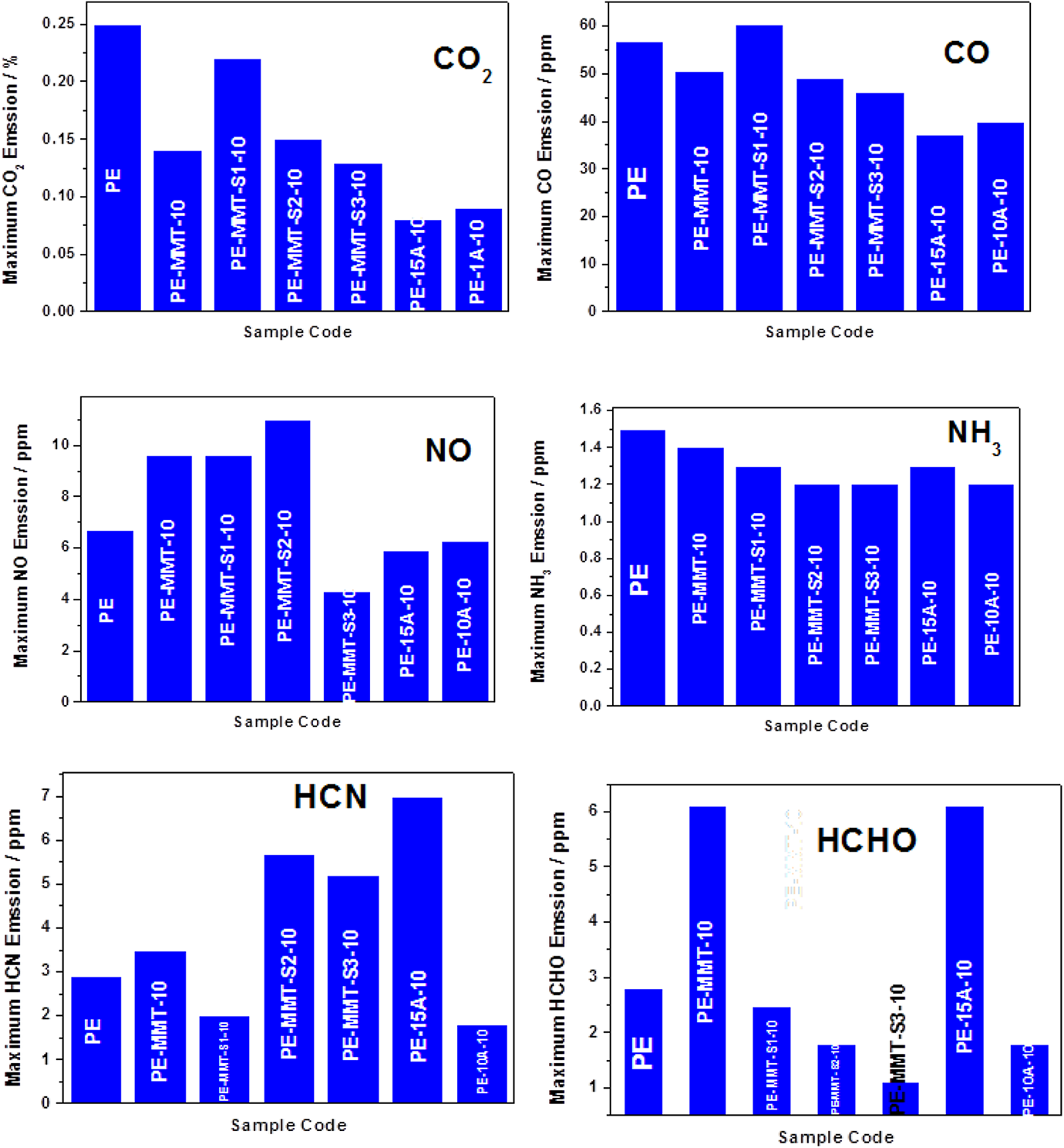
Represents the maximum emission of CO2, CO, NO, NH3, HCN, and HCHO. CO2: carbon dioxide; CO: carbon monoxide; NO: nitric oxide; NH3: ammonia; HCN: hydrogen cyanide; HCHO: formaldehyde.
Conclusions
MMT was functionalized using different side chains organic silanes. The developed organoclays were dispersed in PE producing well exfoliated and dispersed polymer nanocomposites. The exfoliation of organoclay in polymer matrix was elucidated with all techniques. The dispersion of exfoliated organoclay in polymer was proved by microscopic tools. The flammability properties of the newly prepared polymer nanocomposites were significantly reduced. The PHHR was reduced by 48% and AHRR achieved 61% reduction, this in conjunction to reduction of toxic gases emission. Furthermore, the rate of burning of nanocomposite achieving 60% reduction compared to blank polymer. The effect of organic silane side chains used in flame retardancy was evaluated and 3-(trimethoxysilyl)propylamine was found to be the best one. Furthermore, its capability for trigger PE chains for char formation was confirmed. The flame retardancy mechanism was briefly discussed. The emission of toxic gases upon combustion of polymer nanocomposites depends on the type of filler used. Thus, the type of organic modifier playing an important role in directing emission of specific gases and way of pyrolysis.