
Abstract
The extensive growth of telecommunication and electronic devices has led to significant concerns regarding electromagnetic (EM) radiations. Thus, the effect of EM radiations can be reduced by using highly efficient shielding materials. This review aimed to explore the electromagnetic interference (EMI) shielding materials based on polyvinylidene fluoride (PVDF), polyurethane (PU), and polyaniline (PANI) composites. It was found that the composites based on PVDF, PU, and PANI polymers have attracted considerable interest and highly efficient for EMI shielding due to their remarkable properties like lightweight, thermal stability, processing benefits, cheap, tremendous flexibility, and excellent resistance to corrosion. Hence, the PVDF-, PU-, and PANI-based composites are efficient EMI shielding materials.
Keywords
Introduction
In recent years, the rapid use of telecommunication and electronic devices such as cell phones, computers, radio, microwaves, radar system, laptops, and so on have produced the unique form of electronic pollution in the environment like electromagnetic (EM) radiations.1–4 These EM radiations have harmful effects on human health and sensitive electronic devices.5,6 To better solve these problems, electromagnetic interference (EMI) shielding materials have attracted much attention to eliminating undesirable EM radiations.7–9 Thus, the EMI shielding is the most common and excellent source to safe the sensitive electronic devices and human health from the ill-effect of EM radiations.10,11 In the past decade, metal-based shielding materials were the material of choice to combat EM radiations. 12 But metal-based shielding materials have limited application in EMI shielding owing to some properties such as expensive, high specific gravity, difficult to process, reduced flexibility, and corrosiveness.13–15 Alternatively, polymeric composites-based EMI shielding materials have been widely studied16,17 and have attracted enormous attention owing to their unique features like lightweight, thermal stability, processing benefits, cheap, tremendous flexibility, and excellent resistance to corrosion.18–24 These EMI shielding materials are used in the number of important areas such as radar, satellite communication, wireless networking devices, home-based consumer electronics, and so on. The present review discusses various polymeric composites-based shielding materials for the control of EM radiations. It is expected that this review will help to continue research about EMI shielding materials because reviews play a vital role in ongoing interest in new aspects of research in every academic area. Thus, this review mainly focuses on the polyvinylidene fluoride (PVDF), polyurethane (PU), and polyaniline (PANI) composites-based EMI shielding materials. In the recent past, PANI composites have gained much attention due to ease of synthesis, excellent conductivity, tunable chemistry, and tremendous EMI shielding properties compared to the PVDF and PU composites-based EMI shielding materials.
Mechanism of EMI shielding effectiveness
The EMI shielding effectiveness (SE) of shielding materials has the ability to reduce the effects of EM radiations that can be defined as the incident EM wave fall on the surface of materials then a particular part of incident power (Pinc) is reflected (Pref), whereas the certain parts are absorbed (Pabs) and transmitted (Ptrans) of EM radiations. Thus, Pinc can be defined as 25

It is well established that the total EMI SE (SEt) is the summation of three different mechanisms, that is, SE by reflection (SER), SE by absorption (SEA), and SE due to multiple internal reflections (SEM) of EM radiations, which is calculated from the reflectivity (R), absorptivity (A), and transmissivity (T) of the incident EM wave on a slab of materials. It is also well-known that SEM can be neglected if the SEt > 10 dB. Therefore, the SER, SEA, and SET can be calculated by the following equations12,26,27:


Another vital factor is the impedance matching of the EM wave absorbing materials that impact the reflection on the absorbents surface, which can be indicated by the reflection coefficient (
where Zin represents the normalized input impedance of the absorber and can be described as 30
where


According to the transmission line theory, the reflection loss (RL) values can be calculated by the following equation33,34:
For electrically conductive materials, SEA and SER values can also be calculated by the following equations35,36:


where f, μ, σ, and d are the frequency of the EM wave, magnetic permeability, electrical conductivity, and thickness of the shielding materials, respectively.
From the above analysis, we can conclude that the decisive intrinsic factors in SER and SEA of conductive materials (non-magnetism) are

where
Polymeric composites-based EMI shielding materials
In the ongoing research for composites-based EMI shielding materials, we found that the tremendous composites-based shielding materials have properties such as lightweight, high strength, cheap, simple processability, noncorrosive, excellent flexibility, and high thermal stability along with the efficient EM shielding performance. Currently, most of the researchers have now focused on the polymeric composites-based EMI shielding materials and have been widely used in industrial applications such as automotive, military, transportation, aircraft, aerospace, and so on, due to their tremendous properties like excellent resistance to corrosion, lightweight, tremendous flexibility, ease of fabrication, and cost-effective.39–42 The polymers matrix such as insulating and conducting containing conductive fillers known as conductive polymer composites are very suitable for EMI shielding applications and also have been attracted considerable attention in recent years. The polymers matrix chosen in the conductive fillers are divided into intrinsically nonconducting polymers (INCPs) and intrinsically conducting polymers (ICPs). In the INCPs, PVDF and PU whereas, in the ICPs, PANI are the most usually used polymers for the EMI shielding applications.
PVDF composites-based EMI shielding materials
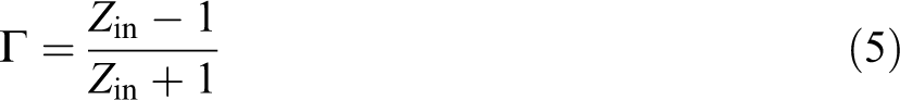
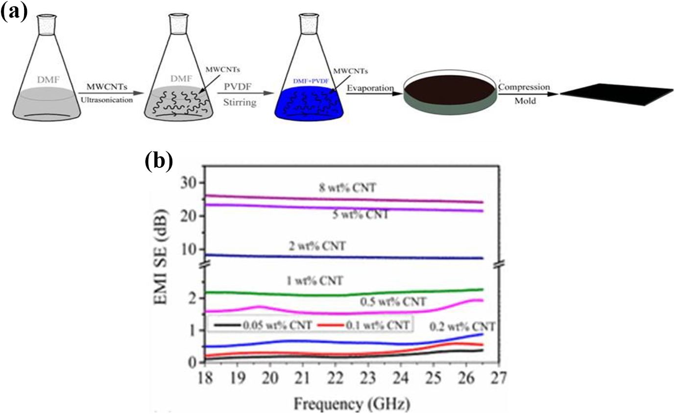
PVDF is a synthetic resin produced by the polymerization of vinylidene fluoride (CH2=CF2). It is a semicrystalline thermoplastic, which possesses excellent flexibility, piezoelectric properties, resistant to flame, good thermal, and chemical stability43–45 and is mostly chosen as a matrix in the conductive fillers for EMI shielding applications. Guo et al. prepared reduced graphene oxide (RGO)/barium titanate (BT)/PVDF composites through a simple solvent casting method. They reported that the synergistic effect of RGO/BT fillers in the PVDF matrix has improved the electrical conductivity and EMI SE performance of RGO/BT/PVDF composite. Finally, the EMI SE of ∼45.3 dB in the frequency range 2–18 GHz was achieved at the loading of 15 wt% of filler. 46 Lee et al. prepared carbon nanofibers (CFs)/PVDF composites through a solution mixing technique. It has been observed that homogenously dispersed CFs as conductive fillers in a PVDF matrix has enhanced the electrical conductivity and EMI shielding performance of composites and finally obtained EMI SE of ∼14 dB at the loading of 10 wt% of filler in the 500 MHz–1.5 GHz frequency range. 47 Ram et al. prepared PVDF/multiwalled carbon nanotube (MWCNT) composite through solution casting method. They observed that the electrical conductivity and EMI SE performance of PVDF/MWCNT composites have significantly enhanced by adding the MWCNT in the PVDF and finally obtained EMI SE of ∼35 dB at loading of 5 wt% of MWCNT in the 8–12 GHz frequency range (Figure 1(a) and (b)). 48
(a) EMI SE of PVDF/MWCNT composites in the 8–12 GHz frequency range by different MWCNT content and (b) EMI SE of PVDF/MWCNT composites at different frequencies versus MWCNT content. Reproduced with permission from reference. 48 Copyright 2018 Wiley.
Zhao et al. prepared PVDF/MWCNT composite film by solution casting method followed by compression molding as shown in Figure 2(a). They reported that the electrical conductivity and EMI SE performance of PVDF/MWCNT composite have significantly enhanced by adding the MWCNT in the PVDF. Thus, the EMI SE of composite films containing 8 wt% of MWCNT was found to be ∼25.02 dB in the 18–26.5 GHz frequency range (Figure 2(b)). 49 Zha et al. prepared PVDF/ethylene-α-octene block copolymer/MWCNT composite through melt compounding and showed that these composite had improved the dielectric, mechanical, and EMI SE performance. Thus, the EMI SE of ∼34 dB was obtained by loading of 2.7 vol% MWCNT in the 8–12 GHz frequency range. 50
(a) Schematic representation of the preparation process of PVDF/MWCNT composite films and (b) plot of EMI SE of PVDF/MWCNT composite by using various MWCNT content in the 18–26.5 GHz frequency range. Reproduced with permission from reference. 49 Copyright 2017 ACS.
Wang et al. prepared segregated PVDF/carbon black (CB) composites containing magnetic carbonyl iron (Cl) particles through blending and hot compaction, as shown in Figure 3(a). It was observed that the electrical conductivity, magnetic, and EMI SE of PVDF/CB/Cl composite have significantly improved. Thus, the EMI SE of 20–27 dB was achieved by loading of 3 wt% of CB and 20 wt% Cl in the PVDF (5.4–18 GHz frequency range) (Figure 3(b)). Additionally, the increased content of Cl in the composites has enhanced the SET and SEA properties of composites, but the SER of composites was negligible (Figure 3(c)). As a consequence, the absorption attenuation is the dominant EMI shielding mechanism of the composite. 51 Gebretrstos et al. prepared PVDF/MWCNT composite through hot rolling. They reported that the flow-induced alignment of MWCNT in the PVDF has improved the electrical, mechanical, and EMI SE of the composite. The stacking five individuals rolled sheets with EMI shielding mechanism, as shown in Figure 4(a). As we can see (Figure 4(b)) the loading of MWCNT in the PVDF has significantly increased the EMI SE of composites and finally obtained EMI SE of −25 dB by loading of 2 wt% MWNT in the 12–18 GHz frequency range. 52
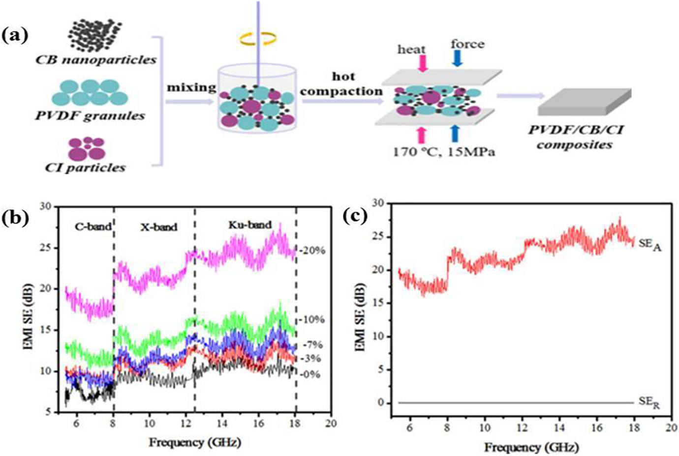
(a) Schematic representation of the preparation process of PVDF/CB/Cl composites, (b) EMI SE of PVDF/CB/Cl composites with various Cl loading, and (c) SEA and SER values of PVDF/CB/Cl composites at 20 wt% Cl content. Reproduced with permission from reference. 51 Copyright 2018 IOP.
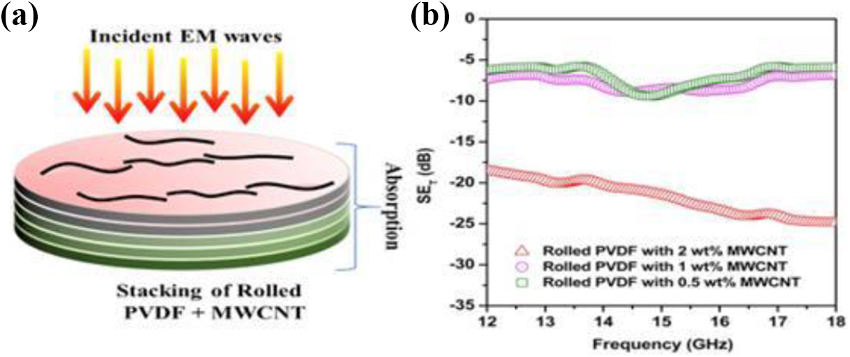
(a) Schematic representation of stacking five individuals rolled sheets with EMI shielding mechanism and (b) SET of PVDF/MWCNT composites with different MWCNT loadings in the of 12–18 GHz frequency range. Reproduced with permission from reference. 52 Copyright 2019 Elsevier.
PU composites-based EMI shielding materials
PU has been widely used in several technological applications due to its tremendous properties such as easy processability, chemical resistance, high tensile strength, and mechanical properties.53,54 Recently, PU has gained considerable research attention and has been chosen as a matrix in the conductive fillers for EMI shielding applications.55–57 Ji et al. prepared flexible and flame retarding thermoplastic polyurethane (TPU) composites through coextrusion technology. They reported that the multilayer-assembled approach was proposed to balance the flame retarding, mechanical, and EMI SE. 58 Bansala et al. prepared graphene/TPU composites by using a solvent casting method. The addition of graphene with the TPU has significantly enhanced the electrical conductivity and EMI SE of composites and finally obtained EMI SE of −29.8 dB by loading of 10 wt% graphene in the 12–18 GHz frequency range. 59 Ji et al. prepared TPU/carbon nanotubes (CNTs)/intumescent flame retardants (IFRs) composites by melt compounding. The IFRs were used as eco-friendly additives for improving the flame retardancy of TPU. They reported that the achieved ∼20 dB EMI SE of TPU/CNTs/IFRs composite is not as high as those prepared through other strategies, but its balanced flame retarding and EMI SE performances originating from the synergistic effect of CNTs and IFRs may still own attractive competitiveness in the field of protective materials. 60 Ghosh et al. prepared PU/CB composites through dip coating and drying method. The EMI SE (∼65.6 dB) of the composite was achieved by loading of 2 wt% carbon content in the PU (12–18 GHz frequency range). They reported that the prepared composite is a suitable alternative for low-cost durable EMI shielding material. 61 Esfahani et al. prepared TPU/amine-functionalized graphene (mTRGO) composite through solution mixing process. They reported that the electrical conductive and EMI SE of TPU/mTRGO composite are higher as compared with TPU/unmodified graphene (TRGO) which is due to the stronger interaction between the mTRGO filler and the TPU matrix. As Figure 5 shows, the TPU/mTRGO composites presented higher EMI SE than that of TPU/TRGO composites with the same loading. For TPU/mTRGO composite, the EMI SE of ∼24.5 dB was achieved by loading of 5 vol% mTRGO, while for TPU/TRGO composite, the EMI SE of ∼15 dB was achieved by loading of 5 vol% of TRGO (Figure 5(a)). This significant improvement in the EMI SE of TPU/mTRGO composites was attributed to the homogeneous connectivity of the mTRGO in the TPU. As we can see that the increased mTRGO and TRGO content in the composites has significantly enhanced the SET and SEA properties, but the SER was almost negligible with all graphene content (Figure 5(b) and (c)). 62
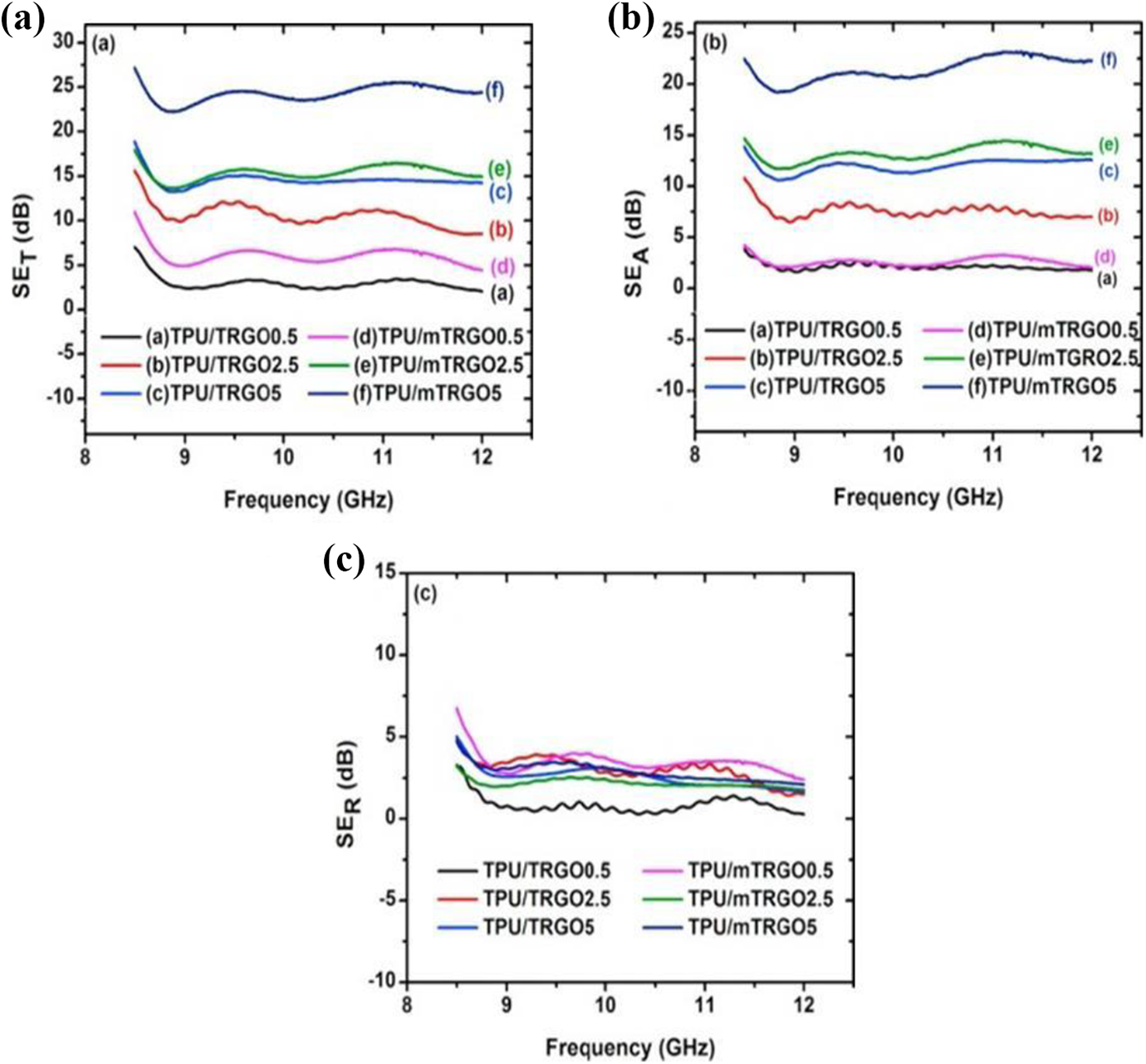
(a) SET, (b) SEA, and (c) SER of TPU/mTRGO and TPU/TRGO composites in the X-band frequency range. Reproduced with permission from reference. 62 Copyright 2017 Elsevier.
Verma et al. prepared PU/RGO (PUG) composites by using the solution mixing process, the fabrication process of the PUG composites, as shown in Figure 6(a). It was found that the EMI SE has significantly improved by RGO content in the PU matrix and finally obtained EMI SE of −21 dB by loading of 5.5 vol% RGO (8–12 GHz frequency range) (Figure 6(b)). This significant improvement in the EMI SE of PUG composite was due to the formation of the electrical conductive network of RGO in the PU matrix. Figure 6(c) shows that, though both SEA and SER increase with the loading of RGO content in the PU matrix, the rate of SEA increases more rapidly compared with SER. This behavior indicates that absorption attenuation is the dominant EMI shielding mechanism of the PUG composites. 63
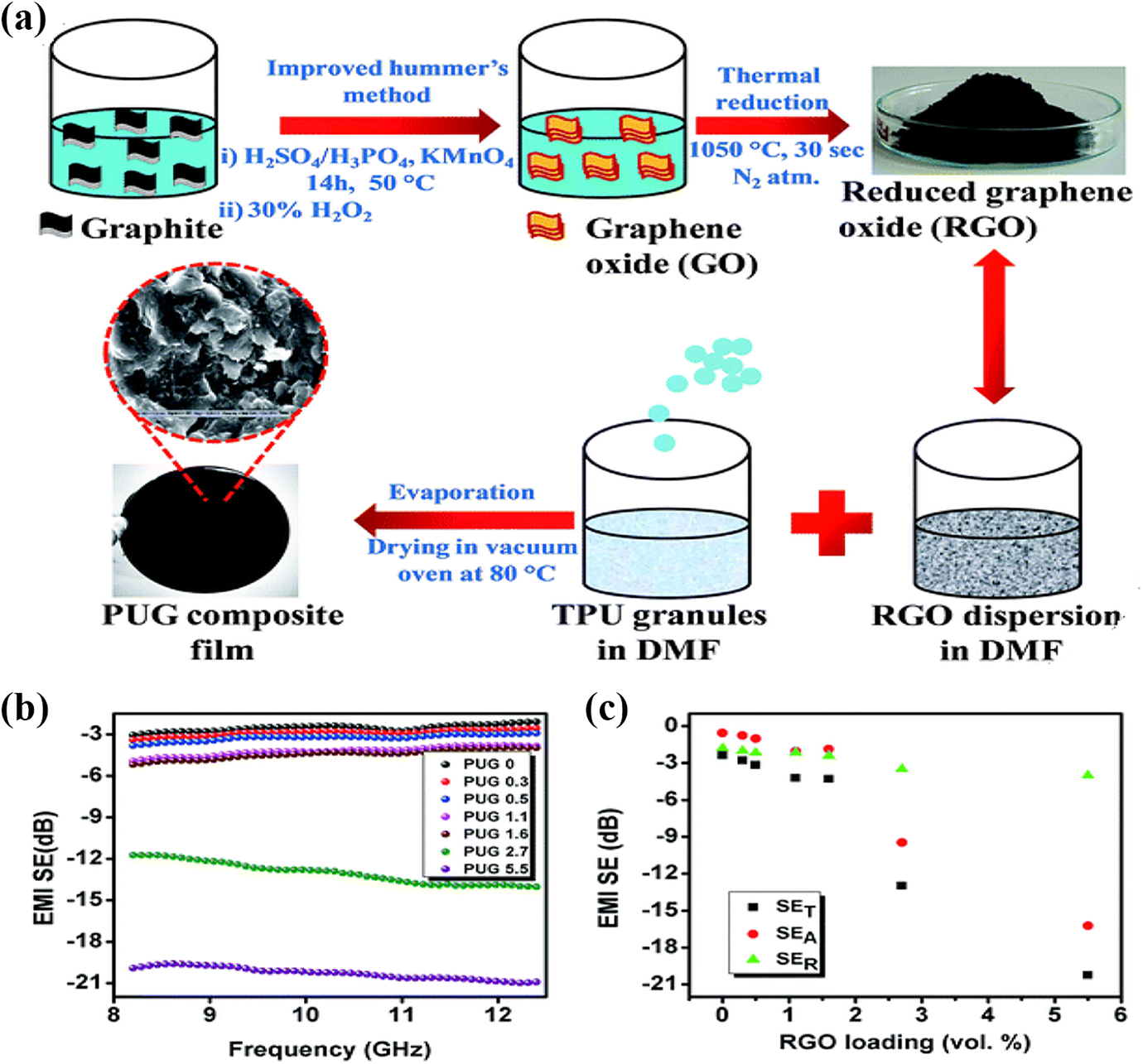
(a) Schematic representation of the fabrication process of PUG composite film, (b) variation in the EMI SE with frequency for PUG composite, and (c) variation in SET, SEA, and SER with RGO loading at X-band frequency range. Reproduced with permission from reference. 63 Copyright 2015 RSC.
Ramôa et al. prepared TPU/CNT and TPU/CB composites by using melt mixing method. They reported that the electrically conductive and EMI SE have strongly dependent on the formation of a conductive network within the TPU matrix. It was observed that with the increase of conductive network (CNT and CB) in the TPU, the electrically conductive and EMI SE of TPU/CNT and TPU/CB composites have significantly increased. Thus, the TPU/CNT and TPU/CB composites were obtained EMI SE of ∼12.2 dB and ∼21.8 dB by loading of 10 wt% of CNT and CB, respectively. The acceptable EMI SE values of TPU/CNT and TPU/CB composites were obtained by loading of 10 and 15 wt% of CNT and CB, respectively, which indicate that these composites are promising candidates for EMI shielding applications (Figure 7(a) and (b)). 64
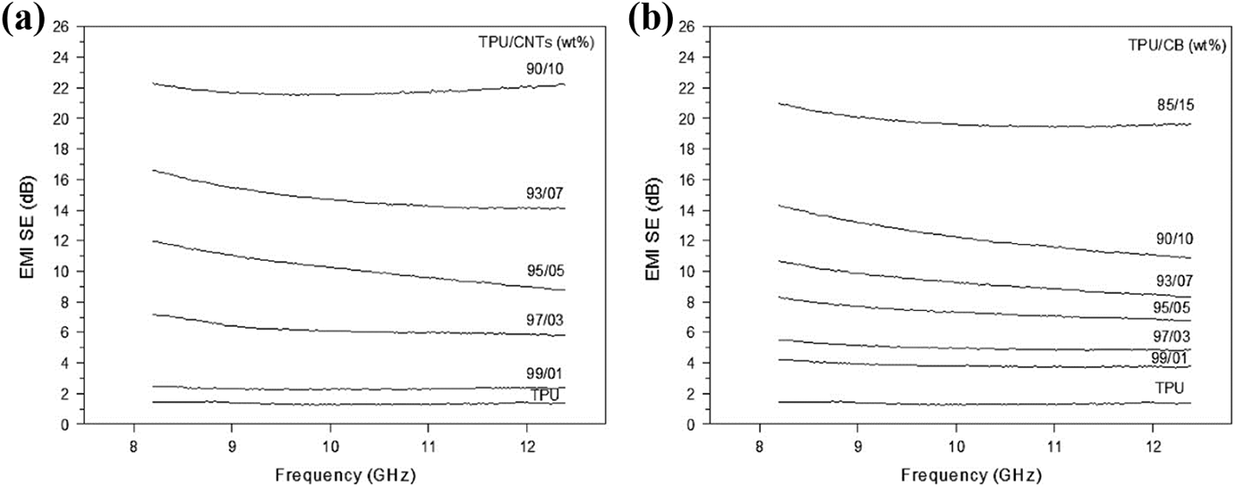
EMI SE of (a) TPU/CNT composites and (b) TPU/CB composites with different loading of CNT and CB contents at X-band frequency range. Reproduced with permission from reference. 64 Copyright 2013 Wiley.
Feng et al. prepared TPU/CNTs composites by using ball milling and microwave sintering technology. First, the ball milling was used to distribute the CNTs onto the surface of TPU granules to obtain the CNTs coated TPU powder and then by microwave irradiation to sinter the powder with a segregated structure to achieve the TPU/CNTs composites (Figure 8). It was observed that the obtained TPU/CNTs composites have tremendous mechanical, electrically conductive, and superb EMI shielding performance. Thus, the electrical conductive and EMI SE of 17.9 S/m and ∼35.3 dB were obtained by loading of 5 wt% CNTs, respectively. 65
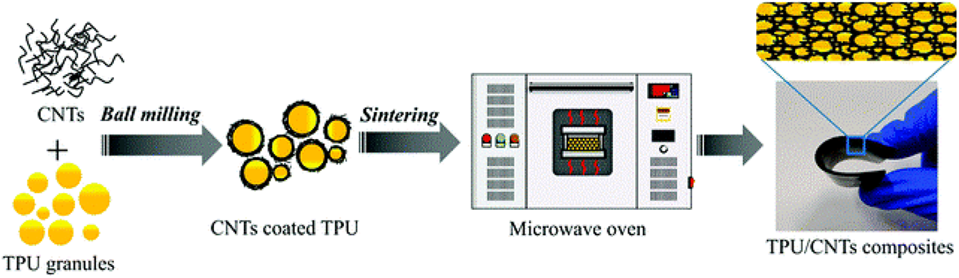
Schematic representation of the preparation process of TPU/CNTs composite. Reproduced with permission from reference. 65 Copyright 2019 RSC.
PANI composites-based EMI shielding materials
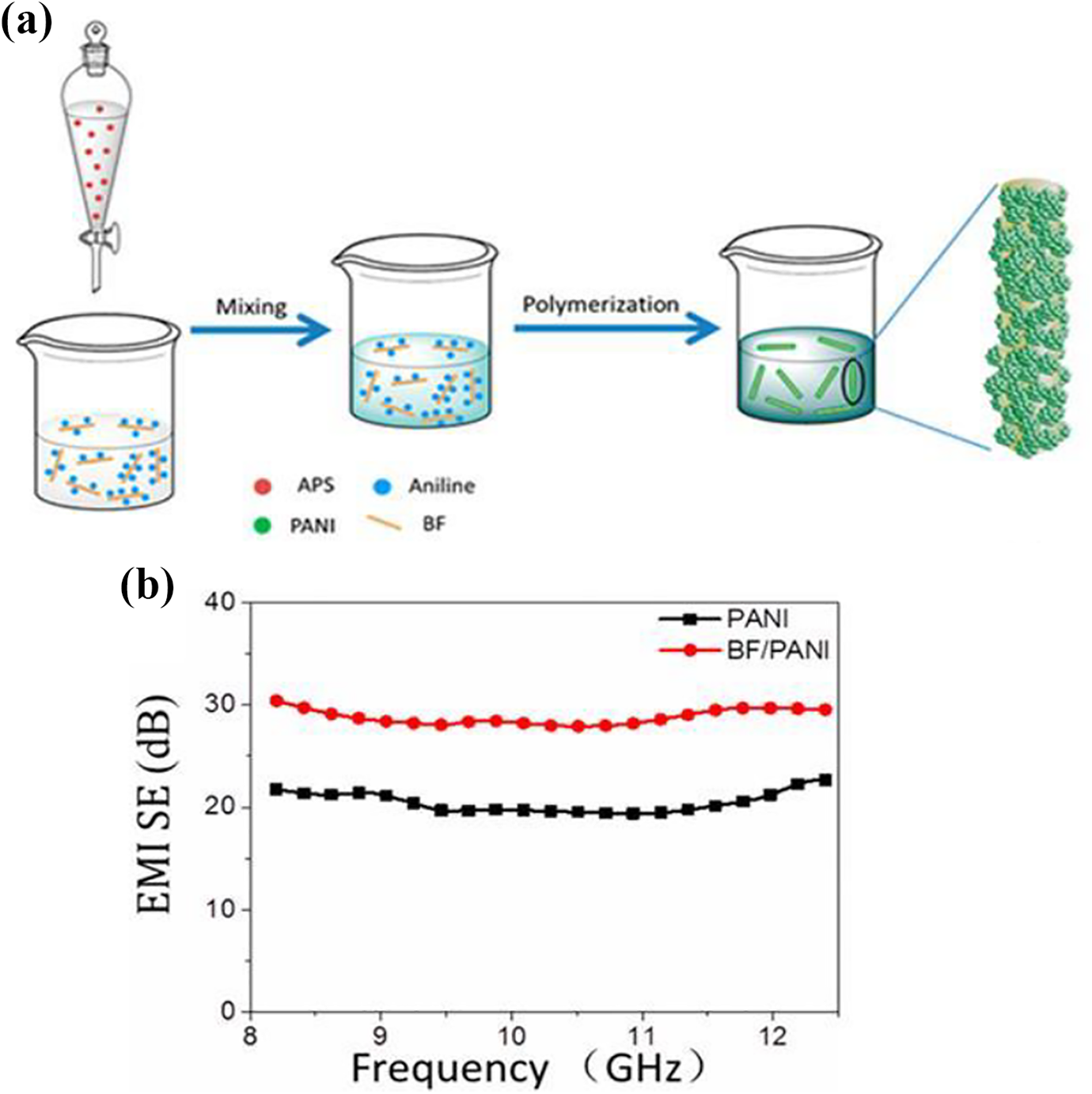
PANI has gained a lot of interest due to its outstanding properties such as facile synthesis, low cost, high electrical conductivity, and superb thermal stability.66,67 PANI is the most common and widely used polymer for EMI shielding applications.68–70 Zhang et al. prepared bagasse fiber (BF)/PANI composites by using in situ polymerization method (Figure 9(a)). They reported that the amount of PANI plays a vital role in the EMI SE of BF/PANI composites. The BF/PANI composites achieved EMI SE of ∼35.73 dB by adjusting the PANI content (Figure 9(b)). They concluded that the BF/PANI composites with excellent EMI SE can be useful for aerospace industries and precious electronic devices. 71 The multiphase hybrid composites of PANI/graphene nanoplatelets (GRNPs) doped with para-toluene sulphonic acid were prepared through in situ polymerization method. EMI SE of PANI/GRNPs composite has significantly enhanced as compared to that of pure PANI and finally achieved EMI SE of −14.5 dB for PANI/GRNPs composite by loading of 10 wt% GRNPs (Figure 10). 72
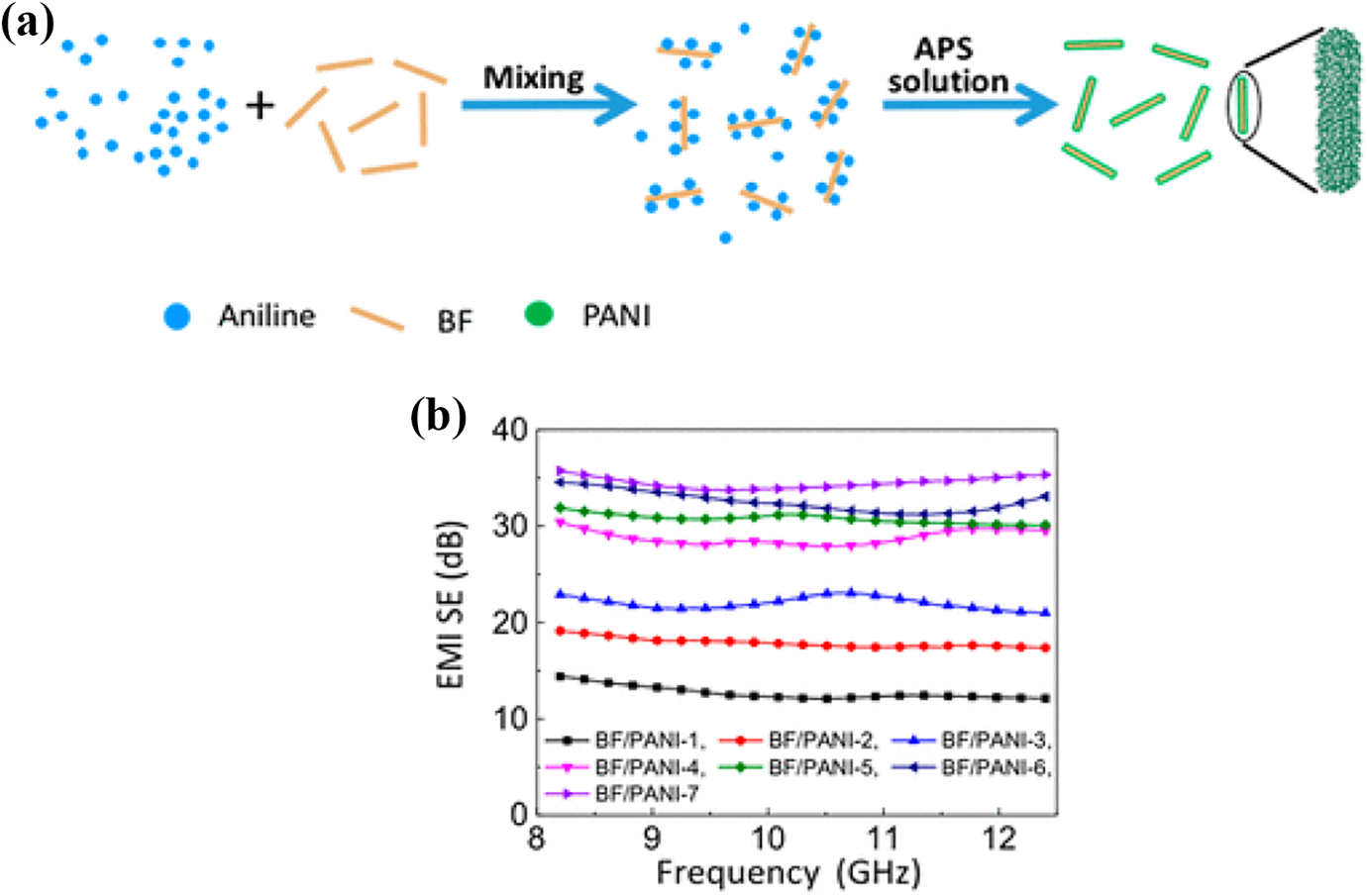
(a) Synthesis strategy of BF/PANI composites and (b) EMI SE of BF/PANI composites at X-band frequency range. Reproduced with permission from reference. 71 Copyright 2019 ACS.
EMI SE of PANI and PANI/GRNPs composites at X-band frequency range. Reproduced with permission from reference. 72 Copyright 2019 Elsevier.
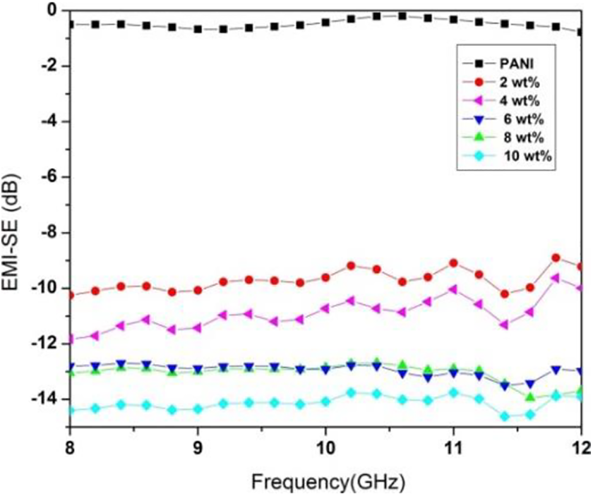
Kumar et al. prepared functionalized f-MWCNT/PANI composites by using solution mixing method (Figure 11(a)). They observed that the resulting f-MWCNT/PANI composites (0–21 vol% CNT) show higher electrical conductivity as compared to that of pure PANI which is due to the formation of conducting network of MWCNT in the PANI. Thus, the increased electrical conductivity of composites has significantly improved the EMI SE and finally achieved EMI SE of ∼12 dB by loading of 21 vol% f-MWCNT (Figure 11(b)). 73 Zhang et al. prepared a hierarchical BF/PANI composite with a core-shell structure by using the in situ polymerization method (Figure 12(a)). They reported that the BF core plays a significant role in inducing the degree of doping and crystalline phase of PANI shell in the final composite. Thus, the electrical conductivity of BF/PANI composite has significantly increased as compared to that of pure PANI. The BF/PANI composite exhibits EMI SE (∼28.8 dB) with a thickness of 0.4 mm (Figure 12(b)). It was found that the dominant mechanism of the EMI SE of BF/PANI composite is absorption. 74
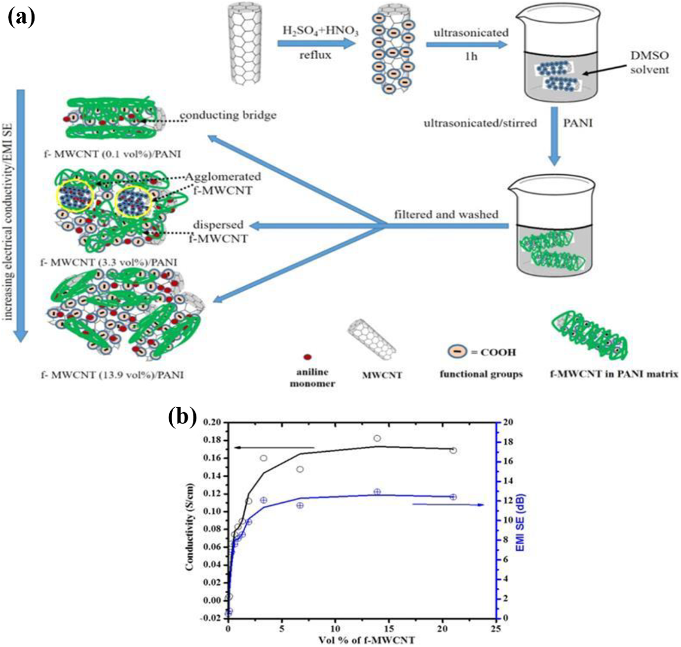
(a) Schematic representation of f-MWCNT/PANI composites and (b) electrical conductivity and EMI SE of f-MWCNT/PANI composites. Reproduced with permission from reference. 73 Copyright 2017 Wiley.
(a) Schematic representation of BF/PANI composite and (b) EMI SE of PANI and BF/PANI composite. Reproduced with permission from reference. 74 Copyright 2017 ACS.
Bora et al. prepared PANI/manganese oxide (MnO2) composite by using the solution mixing method. EMI SE of the PANI/MnO2 composites was investigated by using X-band and Ku-band frequency range. The EMI SE value ∼35 dB of composite in the X-band was observed and ∼39 dB in the Ku-band. EMI shielding due to the absorption of the composite was found to be dominant for both X-band and Ku-band frequency range. 75 Bora et al. prepared PANI/nickel oxide (NiO)-coated cenosphere composite through a solution mixing method. EMI SE of the composite was investigated by using J-band, X-band, and Ku-band frequency range. An average EMI SE of ∼24 dB, ∼27–24 dB, and ∼21 dB was observed of PANI/NiO-coated cenosphere composite in the J-band, X-band, and Ku-band, respectively. EMI shielding due to the absorption of the composite was found to be dominant for composite. 76 Bera et al. prepared PANI/PVDF/ferrosoferric oxide (Fe3O4)/single-walled carbon nanohorn (SWCNH) (PFC) composite through solution mixing and salt leaching process. EMI SE of PFC composite was investigated by using Ku-band and finally obtained EMI SE of ∼29.7 dB for PFC composite at a very low loading of SWCNH (1 wt%). 32 Ismail et al. prepared PANI/cobalt Fe3O4 by using mechanical blending method. The composite obtained a maximum reflection loss of −28.4 dB at 8.1 GHz and −9.6 dB at 11.2 GHz. Thus, these composites showed the absorbing properties in a wide frequency range X-band. 77 Faisal et al. prepared PANI/stannous oxide (SnO)/yttrium trioxide (Y2O3) composites by using in situ polymerization method. The ternary PANI/SnO/Y2O3 composite has shown tremendous microwave absorption properties and finally obtained EMI SE of −42.6 dB in the X-band. 78 Gairola et al. prepared PANI/barium ferrite/expanded graphene composites through in situ polymerization method. They observed that prepared composites have shown better microwave absorption properties and finally achieved EMI SE of ∼37.1 dB in the X-band. 79 Bora et al. prepared PANI/poly(vinyl butyral) (PVB)/cenosphere composites by solution mixing method. In the presence of PANI/cenosphere in the PVB matrix, the time average power of incident EM radiations decreases resulting in an increase of absorbance and finally obtained EMI SE of ∼30.5 dB in the X-band. 80 Joon et al. prepared PANI/carbon fiber (CF) composites by using in situ polymerization method. They observed that the prepared PANI/CF composites have excellent electrical conductivity with improved mechanical strength and thermal stability. In addition, the PANI/CF composite has shown EMI SE of ∼31.9 dB in the X-band. Thus, the PANI/CF composite can be used in the EMI shielding applications due to their tremendous mechanical, electrical, thermal, and EMI shielding performance. 81 Gupta et al. prepared PANI/graphene/MWCNT composites by solvent mixing followed by high-speed homogenization and a ball mixing technique. It was observed that the improvement of the EMI SE is due to the synergistic effect of the graphene and MWCNT in the PANI matrix and finally obtained EMI SE of ∼98 dB in the Ku-band. 82 Singh et al. prepared PANI/gamma-ferric oxide (Fe2O3)-decorated graphene composite through in situ polymerization method. It was observed that the gamma-Fe2O3-decorated graphene in the PANI matrix enhanced the interfacial polarization and the effective anisotropy energy of the composite and as a result more scattering occurs which lead to high EMI SE of ∼51 dB in the X-band. 83 Yun et al. prepared PANI/functionalized MWCNT composites through in situ polymerization method. The uniform coating of PANI on MWCNT played a crucial role in increasing electrical conductivity of composites. The improved interfacial affinity resulted in the high EMI SE of composites and finally obtained EMI SE of ∼47.03 dB in the S-band. 84 The EMI shielding properties of different PVDF, PU, and PANI composites are given in Table 1.
EMI shielding properties of different PVDF, PU, and PANI composites.
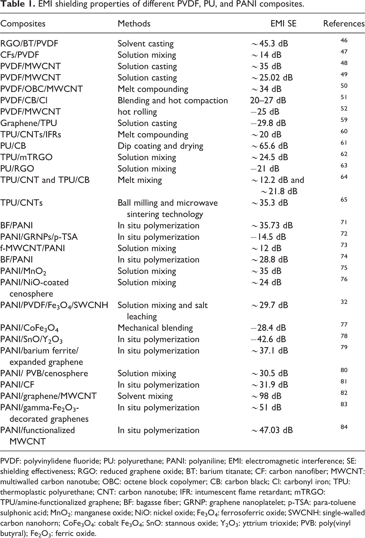
PVDF: polyvinylidene fluoride; PU: polyurethane; PANI: polyaniline; EMI: electromagnetic interference; SE: shielding effectiveness; RGO: reduced graphene oxide; BT: barium titanate; CF: carbon nanofiber; MWCNT: multiwalled carbon nanotube; OBC: octene block copolymer; CB: carbon black; Cl: carbonyl iron; TPU: thermoplastic polyurethane; CNT: carbon nanotube; IFR: intumescent flame retardant; mTRGO: TPU/amine-functionalized graphene; BF: bagasse fiber; GRNP: graphene nanoplatelet; p-TSA: para-toluene sulphonic acid; MnO2: manganese oxide; NiO: nickel oxide; Fe3O4: ferrosoferric oxide; SWCNH: single-walled carbon nanohorn; CoFe3O4: cobalt Fe3O4; SnO: stannous oxide; Y2O3: yttrium trioxide; PVB: poly(vinyl butyral); Fe2O3: ferric oxide.
Conclusion
This review mainly focused on the PVDF-, PU-, and PANI-based composites for EMI shielding properties. Recently, PVDF, PU, and PANI composites have attracted enormous attention and have been widely studied for EMI shielding properties due to their outstanding features like lightweight, thermal stability, processing benefits, cheap, tremendous flexibility, and excellent resistance to corrosion. A detailed overview of up to date research on PVDF, PU, and PANI composites-based EMI shielding materials has been discussed. It is expected that this review will benefit ongoing research relating to EMI shielding applications.