
Abstract
Continuous fibre-reinforced composites have significant industrial importance and usage. However, they are limited by design considerations and high-cost manufacturing operations. This article presents a way forward to utilize Fused Deposition Modelling – a 3D printing technique – to manufacture continuous carbon fibre-reinforced thermoplastics. Several parameters including number of reinforced layers, material impact and interlayer gap have been investigated and optimized using response surface method. Successful incorporation of modified novel nozzle design in a dual nozzle setup resulted in the realization of controlled manufacturing of continuously reinforced composites leading to reinforced yet smooth surface finished samples. Several samples were made, and mechanical testing, parameter optimization, strength calculations and fracture analysis were carried out. For polylactic acid (PLA), tensile strength of 112 MPa and flexural strength of 164 MPA were achieved – an almost 3 times increase from pure PLA printing. The approach presented in this article can forward continuous fibre-reinforced composites for industrial usage with its controlled fibre layup and programmable thread orientation features.
Keywords
Introduction
Additive manufacturing (AM), in the recent past, has evolved and has gotten recognition as an innovative solution to many of the problems faced by traditional manufacturing approaches. It promises to reduce manufacturing time and cost, increases operational flexibility, reduces burden on the supply chain, relaxes operators and more importantly it promises to manufacture virtually anything designable in a Computer Aided Design (CAD) software. It is safe to say that AM is going to be the impromptu solution for designers and manufacturers worldwide in as less as a decade from now. 1
AM is an innovative approach for fabricating complex parts with relatively shorter lead times, reduced scrap wastage, multiple design iterations, reduced material requirements/costs and an overall positive environmental impact. 2 It manufactures in a layered fashion by binding, gluing or joining materials by the use of thermal, chemical, mechanical or optical methods instead of cutting or scraping away material as a contrast to the conventional manufacturing approach thereby ensuring minimal wastage of often expensive and rare materials.
Despite rapid advancements in AM, there are still a lot of difficulties and challenges being faced to establish AM as a fully functional and cost-effective replacement for the traditional manufacturing techniques and processes. Better or at least comparable material, physical and chemical properties need to be guaranteed by AM in order to substitute traditional manufacturing techniques.3,4 Some of the problems being faced by industry include material availability, availability of affordable industrial and even research grade AM equipment, lack of mass customization-based mass production processes, education and training requirements, post-processing, comparatively longer manufacturing times, nonlinearity (reliability in production, i.e. lack of worldwide standardization) and surface quality.4–8
Nevertheless, having started mainly as a prototyping tool, AM is rapidly advancing to many other industrial applications. However, for many of the industrial applications, the mechanical properties and strengths achieved through 3D printing techniques are considerably low. Many efforts are underway to enhance these strengths including orientation analysis, material studies, machine designs and parameter optimizations. Of particular interest are the multiple parameters being explored in 3D printing FDM – Fused Deposition Modelling technique. FDM 3D printing technique is a rapidly emerging, low-cost and a very promising AM technique.9,10 A thermoplastic polymer is heated to above its glass transition temperature in the heating block and extruded from a nozzle while in its molten form. On contact with the layup bed, the molten thermoplastic instantly solidifies. The deposition pattern is controlled by specialized 3D printing software; therefore, essentially, all shapes are virtually possible with minimum material wastage and low energy consumption.11–13 FDM technique is primarily being used for simple thermoplastic parts with very few attempts being made to employ the technique for composite manufacturing. The present research also focuses on FDM and explores options to maximize the mechanical properties of produced parts by impregnating thermoplastics with continuous carbon fibre thread via a novel dual-nozzle-modified process.
Continuous fibre-reinforced thermoplastic composites (CFRTPCs) are beneficial due to their superior strength to weight ratios, easier and low-cost repairs and superior mechanical properties as compared to simple thermoplastics. Multiple composite layup methods have been thoroughly investigated; however, all suffer problems of high-cost molds, imperfect fibre alignment, long production runs and structural fabrication limitations.13–15 3D printing enables the manufacturing of even complex-shaped parts at low operational and material cost to produce high functioning parts with superior mechanical, chemical and structural properties. 4 In the recent years, there has been growing interest in developing better functional parts with the introduction of fibres within the 3D printing process4,16,17 or by trying a combination of materials 18 to achieve better strength/weight, higher fatigue limits, increased impact resistance and improved corrosion resistance. 13 Generally, the parts manufactured by FDM utilizing the easily available commercial materials such as Acrylonitrile–Butadiene–Styrene (ABS) and Polylactic acid (PLA) suffer from low strength issues 19 which can be increased by the addition of fibres and is also the area of research in this present study.
Carbon fibre has been a popular choice for the manufacturing of composites19,20 particularly through conventional, and most of the time expensive methods of pressurized layups and autoclaves. The use of these technologies provide high-quality and high-strength parts but suffer from high operational costs and are limited by complex and costly mold designs. 3D printing overcomes this difficulty. Virtually any part that is designable in a CAD software can be printed in the layer-by-layer additive approach. 3D printers also facilitate in small batch production of complex parts in a relatively short duration directly from design to prototype to final part production thus eliminating mold costs and associated production overheads. Furthermore, the development of new and innovative technologies for composite manufacturing is always desirable. 21
Some researchers have utilized FDM technique for the manufacturing of composites; however, the majority of them are centred on utilizing a ‘pre-modified’ thermoplastic feedstock. The wide use of modified feedstock is mainly due to the low-cost addition of materials to the thermoplastic enabling quick and cheaper creation of feedstock filament. 4 Such research has shown noticeable improvement in the mechanical properties. 9 The process of addition of reinforcing material is simple; the reinforcing agent (short fibres, pallets, etc.) is mixed with the thermoplastic material (often also in pallet or powder form) in the presence of some binder and the mixture is then extruded into filaments of the desired diameter.4,22 ABS feedstock reinforced with short carbon fibre was investigated by Tekinalp et al. 23 for its mechanical properties and porosity defects while an almost 39% increase in tensile strength was reported by Shofner et al. 24 due to the addition of carbon nanofibers in ABS. Ning et al. 25 showed that off-the-shelf 5 wt.% short carbon fibre ABS provided the best mechanical properties, with any further addition of fibre content lowering the performance due to the increase in interlaminar voids. Moreover, with the increase in fibre content the issues of breaking down of reinforcing fibres during printing, 23 nozzle clogging and uneven roughness also creates operational problems.
3D printing of continuous fibre-reinforced parts is still an infancy stage manufacturing process due to the inherent operational difficulties. 4 The process requires simultaneous operations of thermoplastic melting, fibre thread feeding, and combined extrusion of both thermoplastic and fibre in a layer-by-layer process to realize the final geometry of part. Theoretically, like almost all AM processes, it is possible to manufacture complex parts with the desired quantity, direction and volume of threads. It provides the advantages of rapid manufacturing at low cost without incorporating expensive molds. However, the process is greatly influenced by a number of parameters like type of 3D printing, speed, feed rate, build orientation, temperature, filament/thread diameter, thread quantity/type and orientation, layer height, bead thickness, ironing parameters, type/quality of machine, type of material and so on. Finding the right print conditions is difficult 10 and iterative, often requiring multiple prototype runs. In conclusion, however, continuous fibre-reinforced thermoplastics will have better properties as compared to the parts manufactured by short fibre addition. 19
Tian et al. 26 developed a novel approach to 3D print PLA samples reinforced with continuous carbon fibre thread to reach a considerably high flexural strength of 335 MPa. Subsequently, Yang et al. 12 researched simultaneous carbon fibre and ABS layup with flexural strength increase to 127 MPa and tensile strength increase to 147 MPa. They had12,26 developed an approach whereby the heating head was modified to receive both the thermoplastic filament as well as the carbon fibre thread to extrude out via a nozzle of 2 mm diameter. The extruded thermoplastic instantly gets solidified and results in a pull on the thread. After one layer is deposited, the head moves on to the next layer equal to the predesignated layer height with thread still being pulled out continuously. Layer by layer the complete geometry is printed with a continuous thread inside each layer. Tian et al. 26 and Yang et al. 12 were successful in manufacturing some parts through their process demonstrating the effectiveness of the 3D printing process to manufacture CFRTPCs for widespread industrial applications; however, they both recommended further study to investigate and optimize various printing parameters.
Nanya et al. 27 also developed a novel approach using 1 K carbon fibre and PLA filament to prepare continuous fibre-reinforced samples and tested their mechanical properties. Considerable voids at corners were observed in the samples during microscopic morphology analysis; however, they showed improvement with the use of treated carbon fibre. They concluded that tensile and flexural strengths for both treated and untreated carbon fibre-reinforced PLA samples were considerably higher than pure PLA samples. ‘Composite 2.0’ term has been coined by Matsuzaki et al. 19 for continuously reinforced additively manufactured samples. They used jute and preheated carbon fibre before feeding it into the heating head of the printer while PLA was directly supplied. A somewhat difficult approach of disintegrating some filaments from ‘24 K carbon fibre’ and then feeding it into the printer was used which might have resulted in uneven fibre content in the final specimens. However, instead of directly printing the CFRTPCs they printed rectangular pieces and cut out the required samples. Another interesting research using carbon fibres to 3D print CFRTPCs used nylon as a matrix material. 28 They analysed layered formations of pure and fibre-reinforced nylon, created various samples and conducted tensile testing to conclude promising strength increases. They also observed that in almost all their samples void formations, in varying sizes, were present and could not be avoided. Dickson et al. 17 used 1.75 mm nylon filament and reinforced it with off-the-shelf 0.3 mm filaments of glass and kevlar and 0.35 mm filament of carbon in concentric and isotropic layouts achieving varying volume fractions. They used a specialized ‘Mark One composite 3D printer’ available with an enclosed printing area and double head. This specialized printer has the advantage to print continuous fibre-reinforced samples but is limited due to its cost and available materials. Tensile and flexural tests were performed to evaluate strength increases with ‘isotropic’ samples yielding the best results. They concluded the potential advantage of 3D printing of composites for industrial usage, however, they also concluded that fibre addition will benefit strength enhancement only up to a certain extent. Increasing thread concentration beyond that will not have substantial benefits while structural integrity, surface finish, interlaminar behaviour, porosity and void formation aspects will deteriorate.
Logically, for 3D printed parts to be used in industry for ultimately replacing conventionally manufactured parts they should at least be comparable in strength to the conventionally manufactured parts 29 and continuous carbon fibre addition (among other fibres) enables them to achieve this goal. However, the major issue remains the somewhat poor interlaminar strength owing to pore defects in the thermoplastic, low fibre layup and orientation control, poor bonding between thread and thermoplastics, and weak layer-to-layer adhesion. 12 The present state of continuous fibre 3D printing is also severely limited by the use of single nozzle printers where thread and thermoplastic have to pass through the same nozzle thus limiting control over fibre, poor overall surface finish and increased voids. The present research aims to improve upon the process by innovatively modifying a nozzle for fibre layup and using a dual extrusion printer to increase process control (Figure 1).
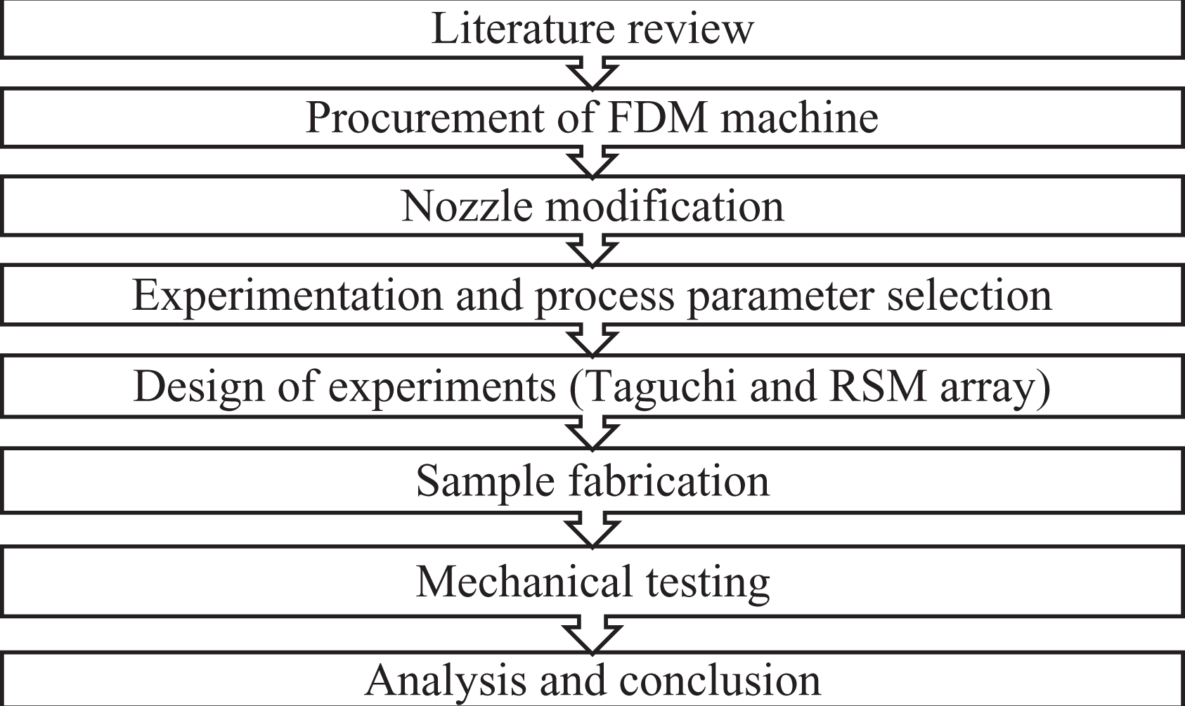
Research methodology.
Methodology and experimentation
Commercially available ‘ANET A-8M’ 3D printer with ‘dual nozzle’ was selected for the research. This printer primarily supports PLA and ABS material and is capable of 260°C hothead and 100°C hotbed and has a bed of 220 × 220 × 220 mm 3 . For the present research, PLA and its variant PLA-Carbon (PLA-C) (and for comparison ABS) have been used due to their easier availability, low-temperature requirements and lower operational costs. All the thermoplastic were from Shenzhen Anet Technology Co., Ltd (Longhua District, Shenzhen, China) certified by Dong Guian BST Testing Co., Ltd, (Dongguan, Guangdong, China) while certified Tenax carbon fibre was procured from ‘Teijin Carbon Shanghai Co., Ltd.’ (Xuhui District, Shanghai, China). To ensure generalizability and a standard method; ASTM standards30–33 were used for this research for designing the CAD files and for tensile/flexural testing. To initiate the final print of samples CAD models were prepared in ProE, imported in STL format to Cura software for slicing (Figure 2) and GCode editing/writing was done in Repetier. During the printing operations, the software feeds one layer at a time to the printer which then extrudes material to complete that layer and subsequently moves on to the next layer. Layer-by-layer manufacturing is carried out in this step-by-step fashion.
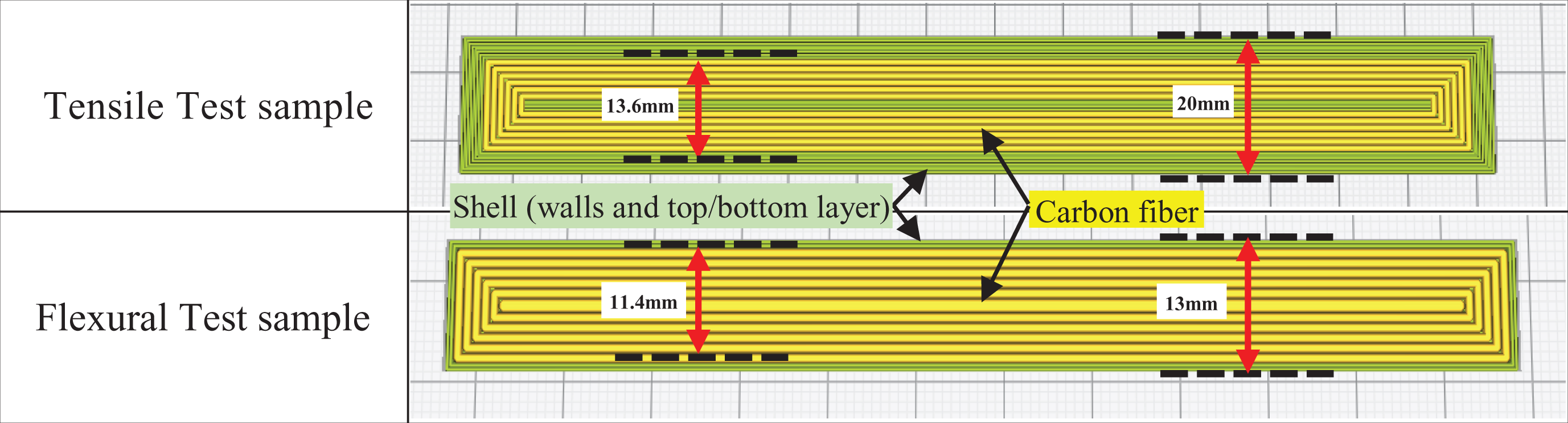
CAD models with thermoplastic and fibre widths.
As compared to short fibre or prefabricated reinforced filament, the use of continuous fibre can greatly enhance the mechanical properties of the resulting part. The aim of the present research is to study the effect of continuous fibre reinforcement on the mechanical properties of thermoplastics. Some researchers have attempted to design nozzles for continuous fibre impregnation however issues of fibre control were experienced.12,26,27 They all had modified an extrusion head to allow fibre thread to flow through it while hothead was heating the thermoplastic, and both get simultaneously extruded and laid up during printing. While the method is novel and has resulted in strength increase of thermoplastics, it suffers from one big limitation; it cannot control the amount of thread being extruded. As there is only one nozzle the thread will start extruding from the first point of printing till completion of print leading to no control of volume fraction, uneven surface finish, possibly exposed threads and delamination problems. To overcome this; dual nozzle printer was used. Careful design analysis was carried out and a novel approach was adopted and subsequently implemented.
Modification of printing head
In addition to using dual nozzles, a two-pronged approach was adopted for fibre impregnation. Initially, the fibre was passed through the feeding tube leading to the heating head following previous researchers. This worked well for braided thread however problems were encountered during 1 K carbon fibre printing. The problem started as soon as the carbon thread reached the heating block where the thread disintegrated. In almost all the attempts made for this process, the disintegrated thread severely clogged the nozzle, heating head as well as the heatsink tube. This resulted in lengthy and cumbersome unclogging/cleaning efforts.
To overcome thread disintegration and nozzle clogging issues; multiple approaches were pondered over (Figure 3). Finally, it was decided to attempt a novel, hitherto untried, approach of directly modifying the nozzle (Figure 3, approach 2). A 1-mm hole was drilled on the side of one of the faces of the nozzle at 45°. The angle was selected to facilitate the flow of the thread into the melted thermoplastic without having the melted thermoplastic flow-out of it. This novel approach resulted in a streamlined printing operation with extremely easy thread handling and monitoring. Furthermore, it was experienced that carbon fibre can also be fed into the nozzle during the printing operation while it is still hot without it getting disintegrated. This resulted in a much efficient printing operation.
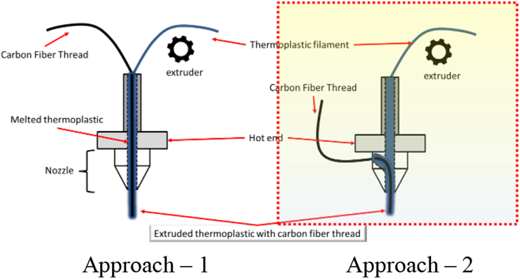
Modification of printing head: (a) approach 1 and (b) approach 2.
As stated by Montgomery 34 to initiate response surface method (RSM) optimization a properly designed experiment is a prerequisite. Therefore, with the initial three ‘target’ parameters of Material, Thread Count and Interlayer Gap, L9 Taguchi array was designed. To initiate this working grid an ‘allowable region of printing’ was also worked out (Figure 4). While designing this region the only limitation considered, at this stage, was that the first and last layer should be of thermoplastic to ensure better adhesion to the printing bed, better adhesion between subsequent fibre layers and a better finish on the external layers with no thread exposed. 28 If the gap is increased beyond this, either the total no of threads cannot be printed or the thread layer becomes exposed in the first or last layer; which is undesirable. Furthermore, as G-Code for each print sample had to be manually prepared a detailed layer-wise data was also required. This data enabled to arrange the fibre-reinforced layer while compiling the GCode. It is worth mentioning that the last sample that was printed was with 60-2 configuration. Beyond that 72-2 sample was not possible as the first and last layer had to be thread layers, that is, gaps of two were not possible beyond this point.
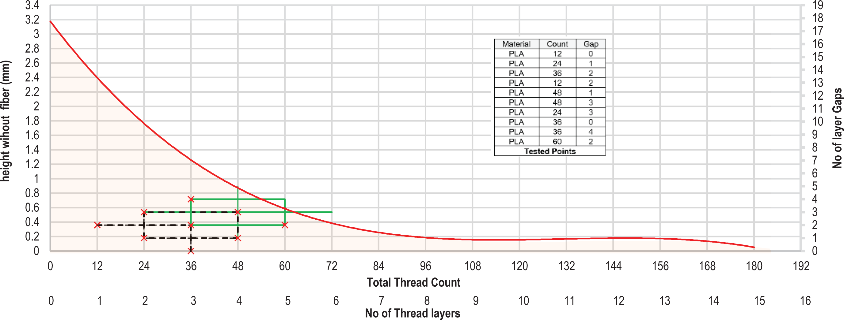
Allowed region and tested points.
To ensure acceptable and repeatable results three iterations were performed following Nanya et al. 27 and ASTM standards,30,33 that is, three samples were printed for each ‘thread count’ and ‘interlayer gap’. Furthermore, to ensure continuity in threads and matrix material, samples for a setting were printed together in one printing run. 28 For L9 Taguchi array, material comprised of PLA, ABS and PLA-C. Thread count comprised of 12, 24 and 36 whereas interlayer gap comprised of 0, 1 and 2. After completion of all tests, the array was analysed to decide on the parameters that are to be optimized. Based on the analysis of Taguchi array, the final RSM array with Central Composite Box Design was designed for PLA with an alpha value of 2. RSM design was analysed using Minitab, RStudio as well as MS Excel to understand the optimization direction. Further samples were then printed (Figures 5 and 6) and tested based on the optimization results.
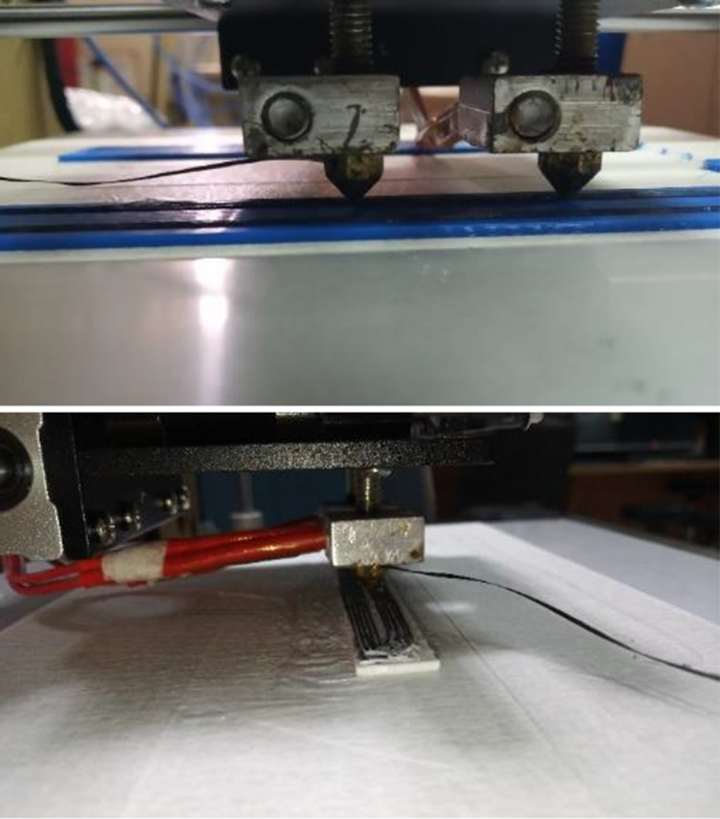
Fibre-reinforced AM. AM: additive manufacturing.
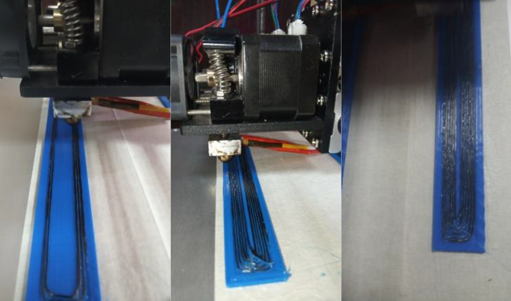
Fibre-reinforced 3D printing.
In the present research, the results recorded for continuous carbon fibre-reinforced PLA samples were much higher than pure PLA samples. Moreover, the results obtained are also considerably higher than previous researchers where short fibre-reinforced thermoplastics were 3D printed.13,23,25 Tensile and flexural testing for all the samples was performed on SHIMADZU AGS-X series machine. In the first run, tensile and bending tests were performed for the Taguchi array to finalize the direction of implementing RSM optimization. For RSM, it was necessary to understand the general strength behaviour of the specimens and more importantly it was critical to finalize which parameters (Material, Thread Count and Interlayer Gap) are to be further investigated. To analyse the Taguchi array, and subsequently RSM array, RStudio was used. All the variables were converted to 1–0 conventional form with centre points as PLA, thread count 24 and interlayer gap 1. RStudio provided a polynomial second-degree equation with weights of each variable along with a pareto chart for coefficient weights and a contour plot with surface response lines.
Results and analysis
Comparative analysis
To establish a trend of the flexural and tensile behaviour, comparative results were plotted (Figures 7 and 8). The dotted line in Figure 8 represents the values for pure thermoplastic samples. These plots assisted in making the best choice of materials for further 3D printing by knowing their respective strengths particularly for implementation of RSM optimization (final selected material was PLA due to higher strength values).
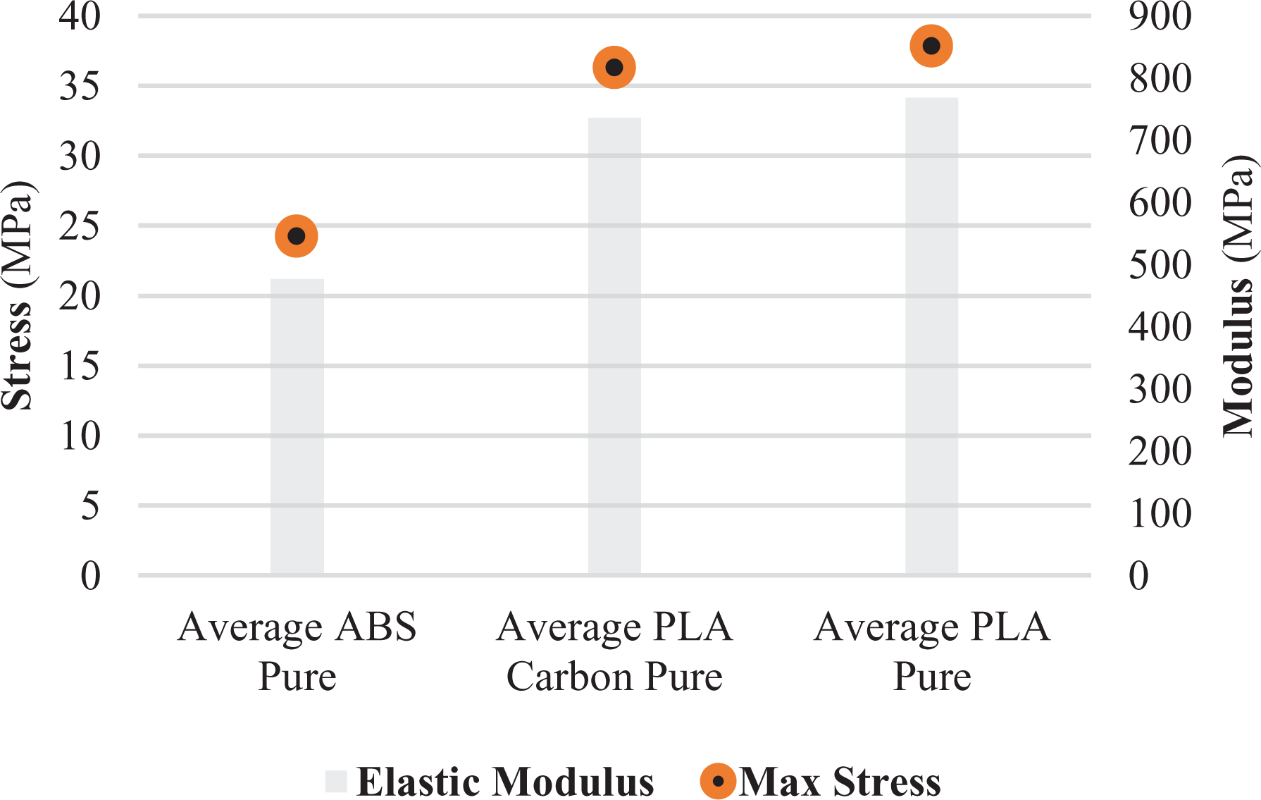
Comparison of pure thermoplastics.
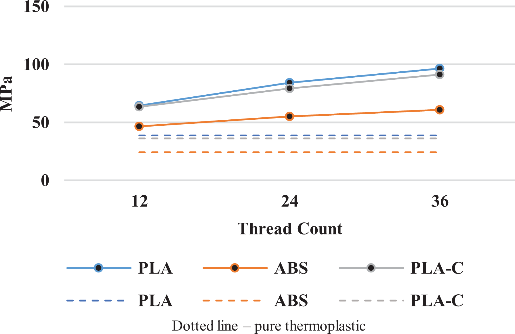
Tensile strength comparison.
Tensile results
As stated earlier, Taguchi and RSM arrays were analysed and based on the results of Taguchi array, RSM optimization was applied within the feasible region (Figure 4).
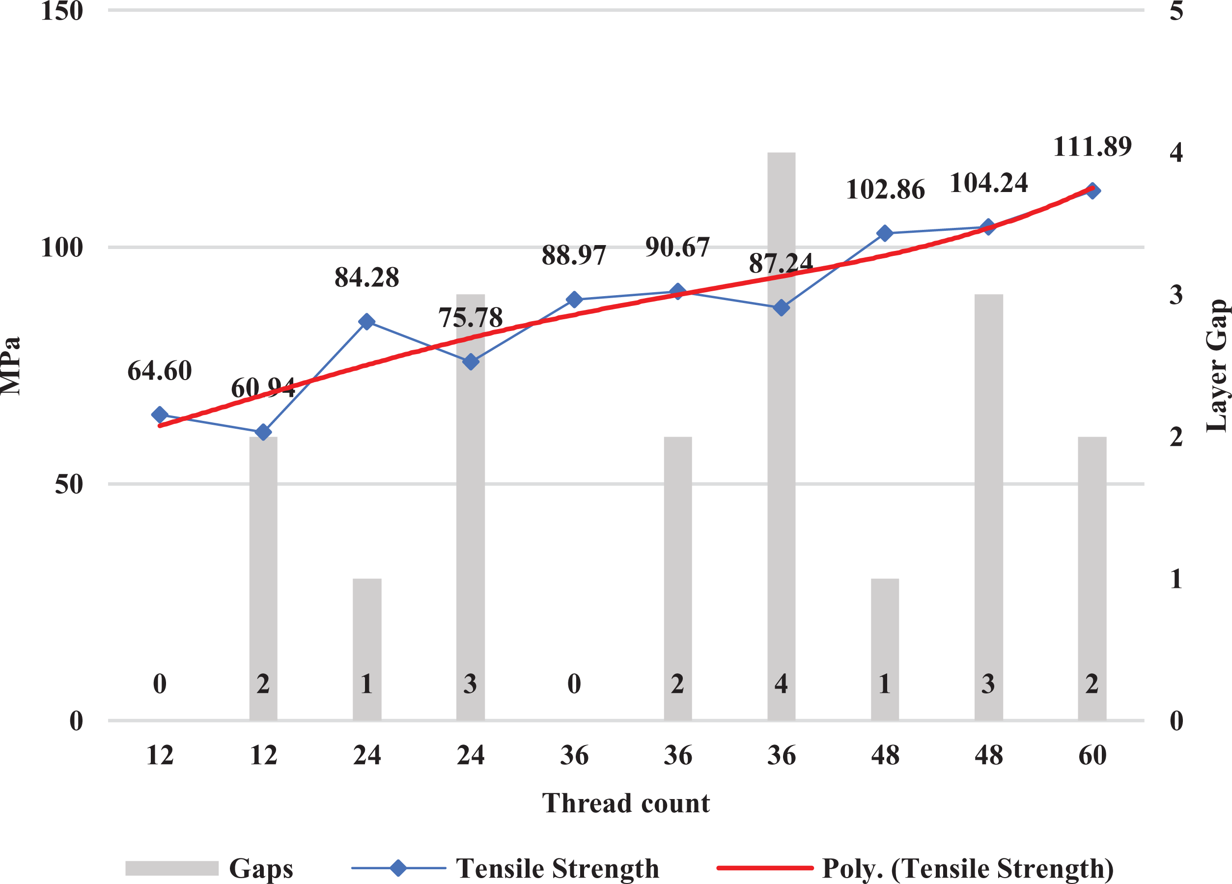
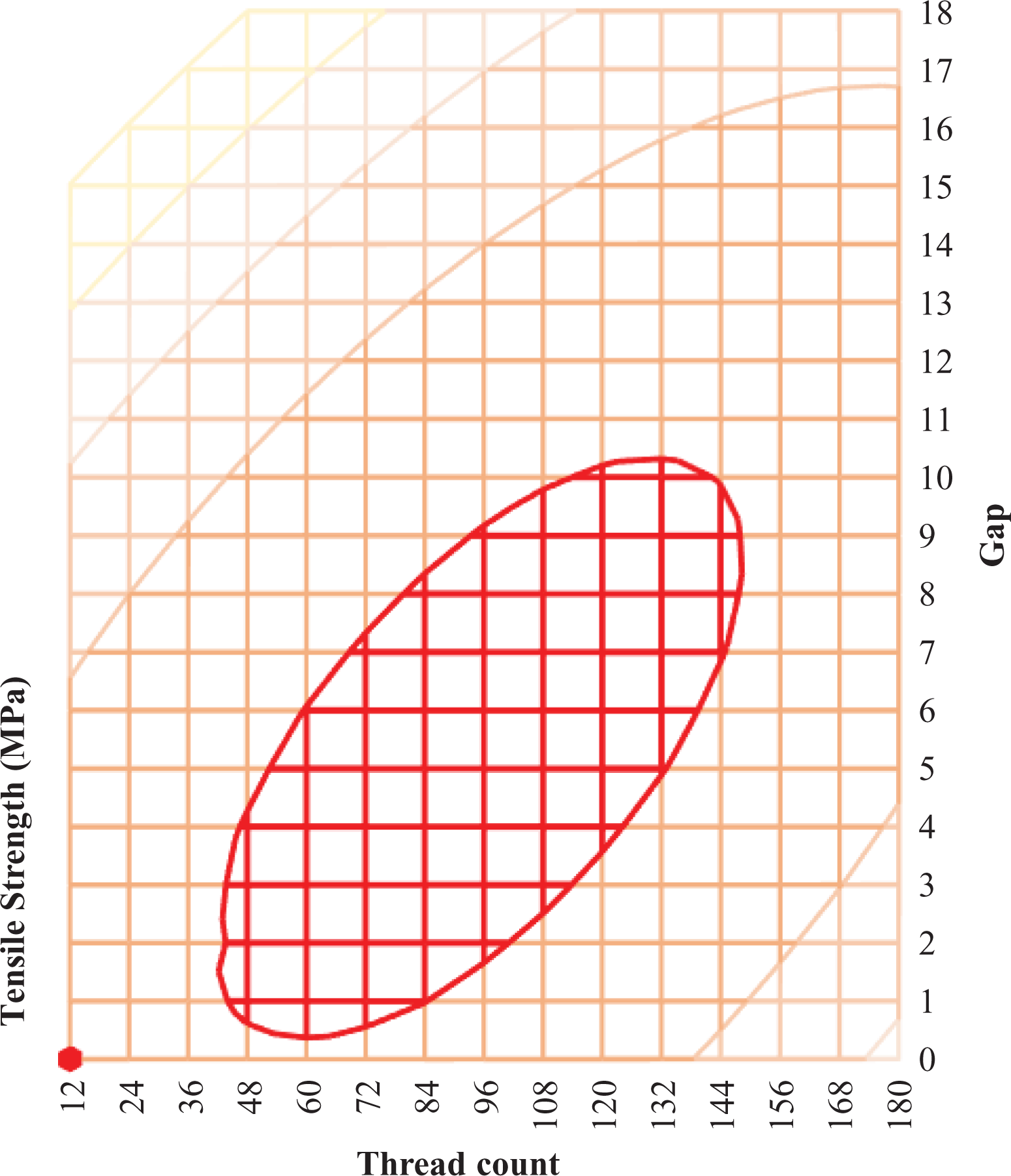
To further analyse experimentally achieved data in Table 1; Figure 9 was plotted providing comparison of tensile strength (Max stress, strain and Youngs Modulus) for all the different Thread and Gap combinations for PLA samples tested for implementation of RSM optimization. The tensile results for carbon-reinforced tensile specimens showed a considerable increase in strength properties. However, to ascertain the exact contribution of variables in optimizing the tensile strength, RStudio was used. Based on the results of RSM, the entire working grid including the areas that were not possible to be printed in our current setup were considered. This enables to visualize the optimum area. Figure 10 shows the contour plot for all thread counts (0–180) and gaps (0–18) for the parametrically bound sample of 3.2 mm thickness where the red highlighted area shows the optimized area for the entire working grid considered for the present research.
Carbon-reinforced PLA tensile comparison (RSM).
RSM plot for tensile working grid.
PLA material RSM results (tensile).
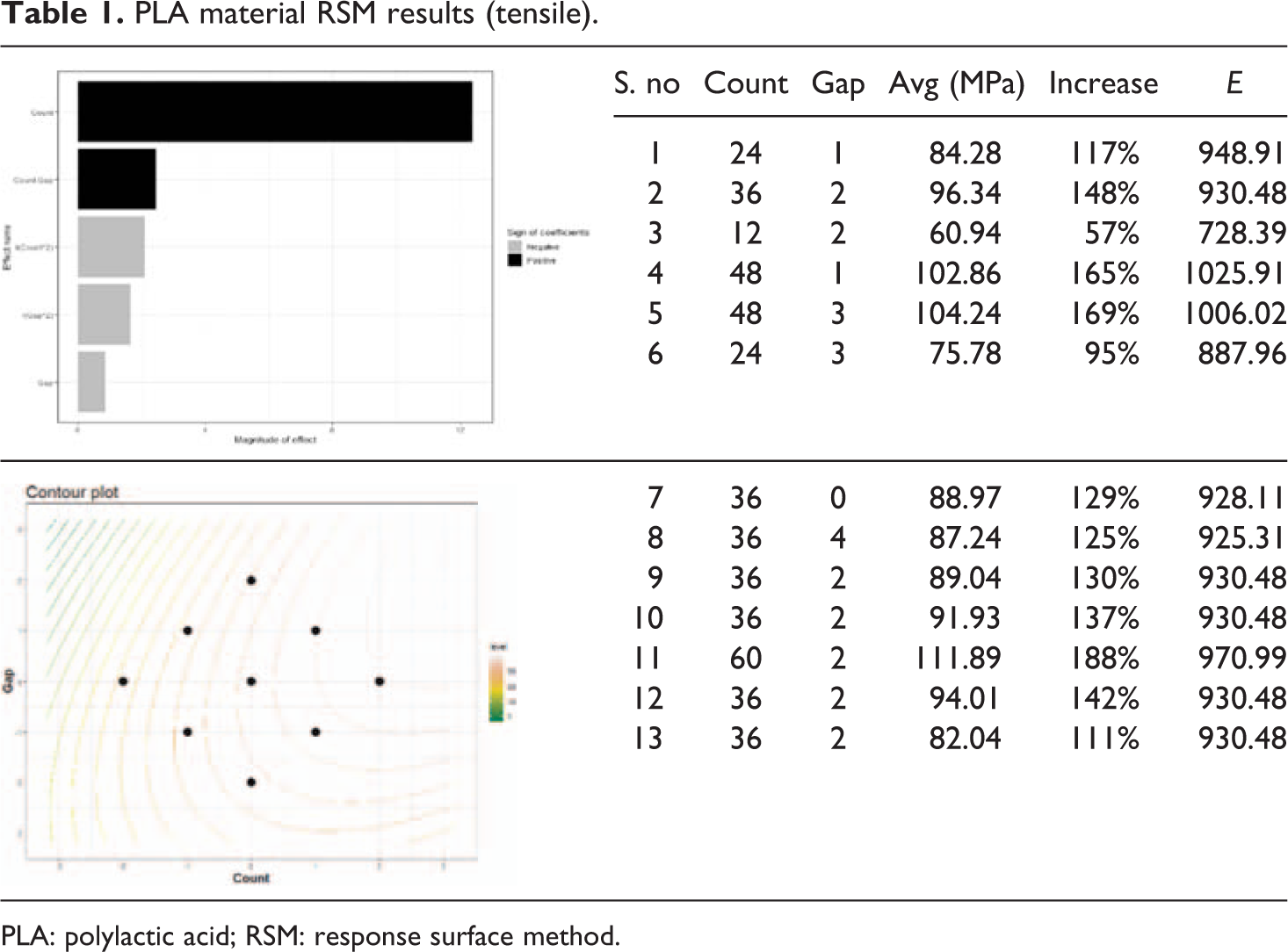
PLA: polylactic acid; RSM: response surface method.
Flexural testing
Similar to tensile testing, printing of flexural samples for Taguchi array was followed by the analysis with subsequent implementation of RSM optimization (Table 2).
PLA material RSM results (flexural).
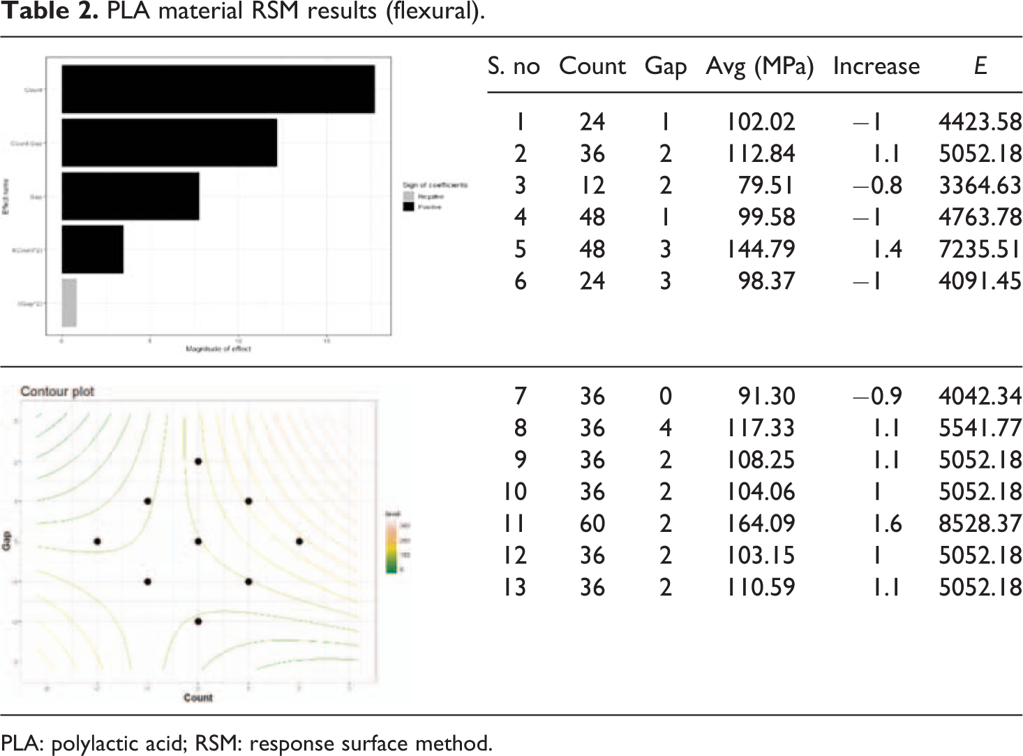
PLA: polylactic acid; RSM: response surface method.
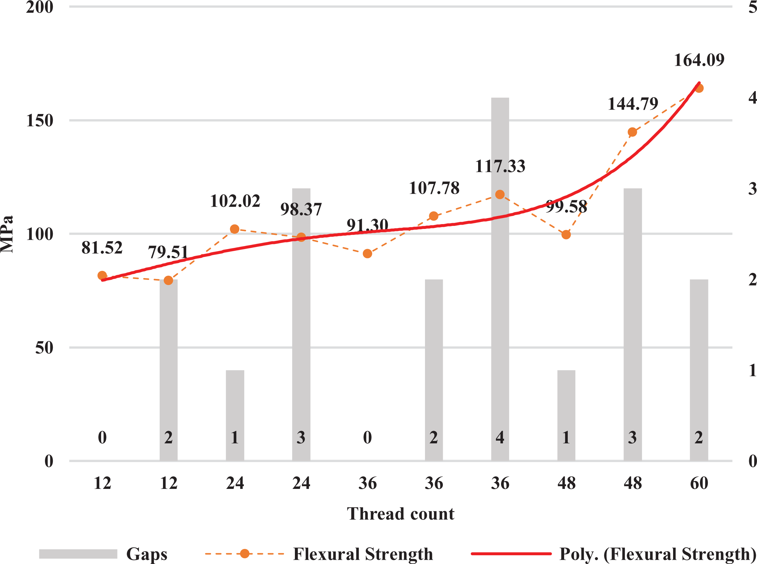
To further analyse Table 2, Figures 11 and 12 were plotted providing comparison of flexural strength between all the different thread count and gap combinations for the PLA samples tested for RSM array. Based on the results of RSM, optimum area was calculated. In most of the cases, the optimum area is generally at or just beyond the boundary conditions. Figure 12 shows the trend lines of flexural behaviour for the entire working grid.
Carbon-reinforced PLA flexural comparison (RSM).
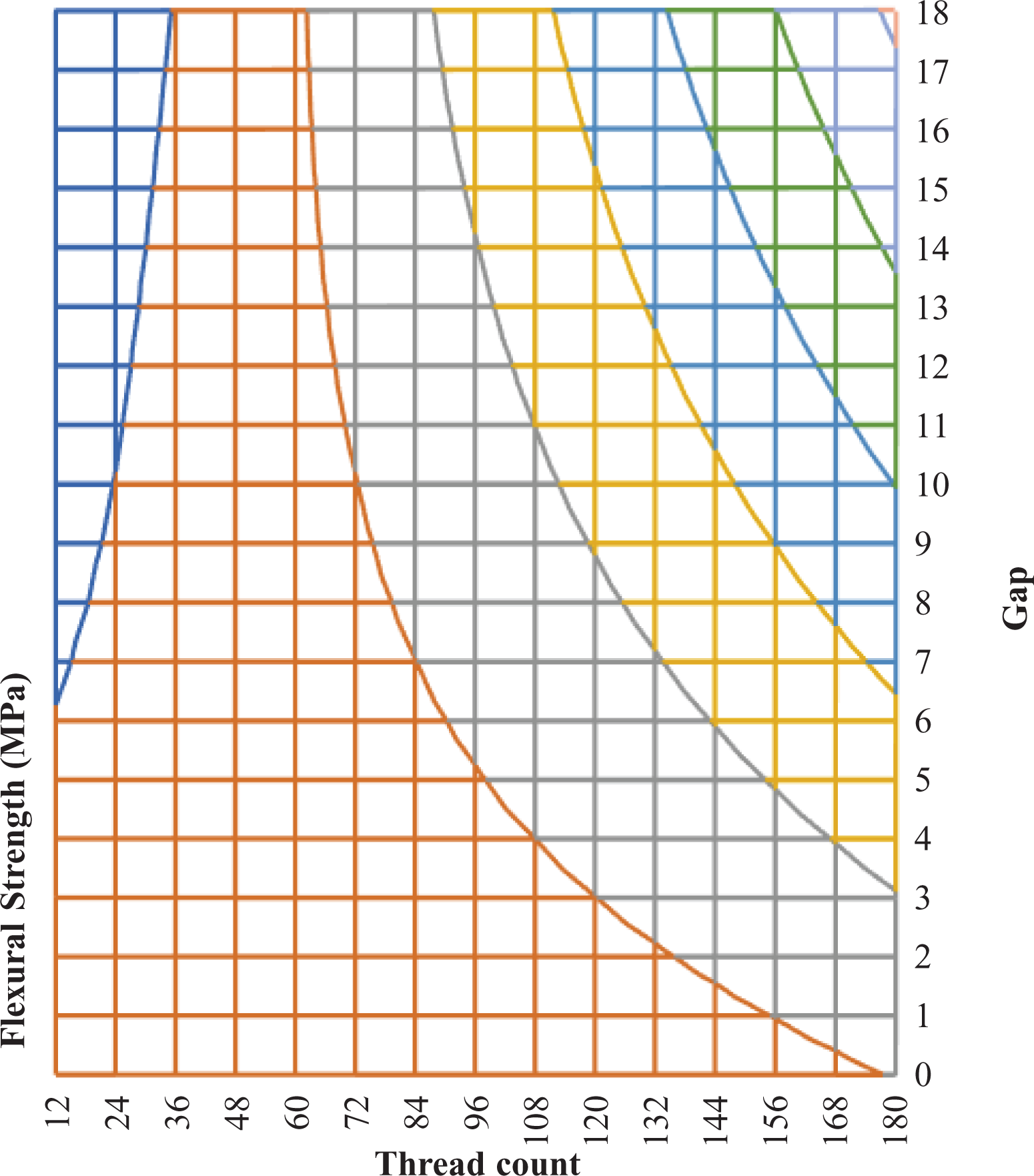
RSM plot for flexural working grid.
Volume fractions
Volume fraction (Vf) of samples printed in the present study is very low. However, the literature review shows that researchers employing similar approaches also faced low Vf issues. Primarily the reason for such low Vf is because to use the FDM process for continuous fibre-reinforced 3D printing it is necessary to have the thread pass through the nozzle. This thus limits the amount of fibre that can be layed up. 19 If a ‘hybrid’ approach is developed where the fibre is pre-laid on the already printed layer followed by covering that by thermoplastic; higher Vf ratios can be obtained however the process will not strictly remain FDM.
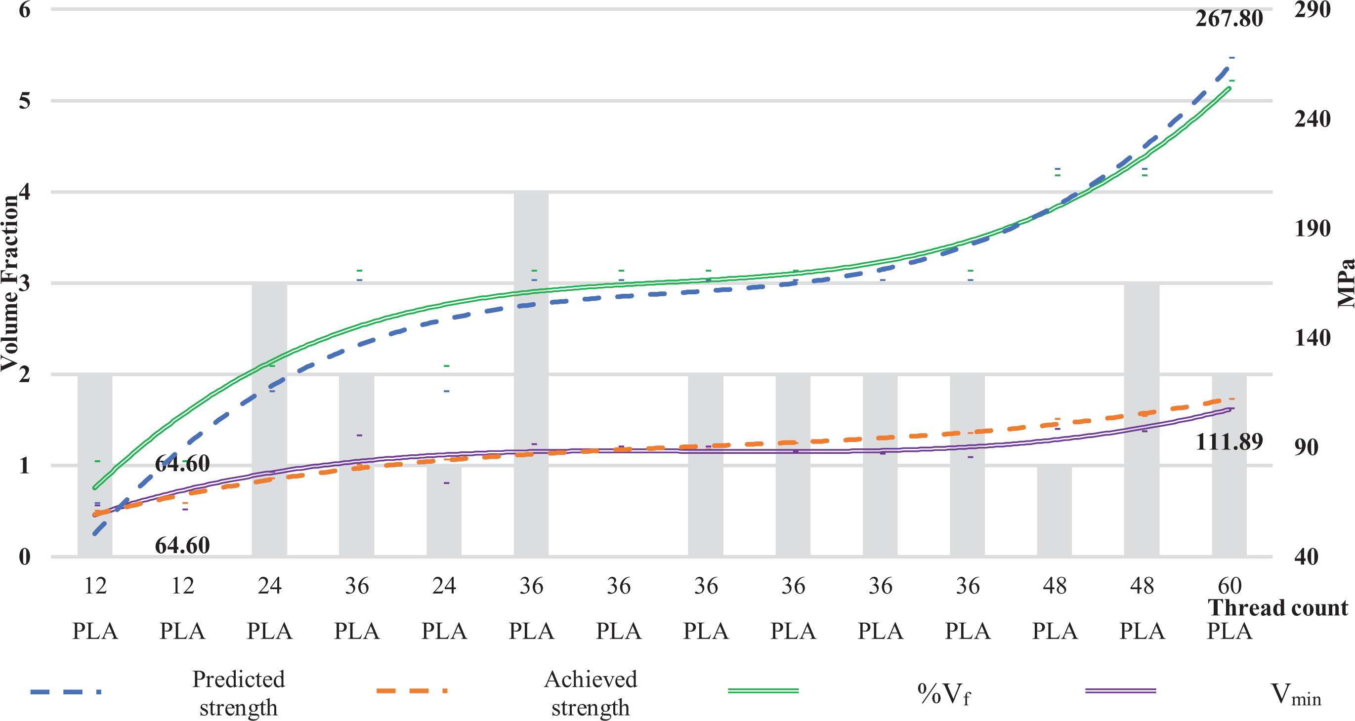
Volume fractions have a direct correlation with the strengths and are an important design parameter while developing new composites. 20 Micromechanics were used to calculate the predicted strengths based on the constituent Vf of fibre and matrix. Rule of mixtures (ROM) strength prediction/calculation equations 35 have been used in the present research (equation (1)). The first step in the process was to clearly define the parameters to be used including no of tows per unit thread width, TEX, ρf (fibre density) and tc (thickness). With 12 threads being laid-up in each layer during FDM layup; calculations were made starting with Equation (1) leading to Figure 13.
Volume fraction correlation with tensile strengths.

Discussion
The present research focused on developing a novel approach for developing an FDM system capable of 3D printing fibre-reinforced parts (Figure 14). A novel approach to realize this was designed, developed and successfully tested. One millimetre hole was drilled on the nozzle and thread was passed through it where thermoplastic was already in a heated and melted form. Under (predominantly) frictional force, the thread was pulled/extruded from the nozzle. The same process was used in the printing of all samples with carbon fibre thread. The tensile and flexural strength values for PLA and ABS 36 were well duplicated, in line with the literature review, during the present research with 38 MPa and 24 MPa tensile strength and 102 MPa and 63 MPa flexural strength for PLA and ABS specimens, respectively. Care was taken throughout the research to use samples and testing procedures as mentioned in ASTM standards to ensure generalization. The highest strength values have been achieved for PLA samples and the lowest for ABS. PLA-C (short fibre off-the-shelf filament) had strength properties in between those of PLA and ABS.
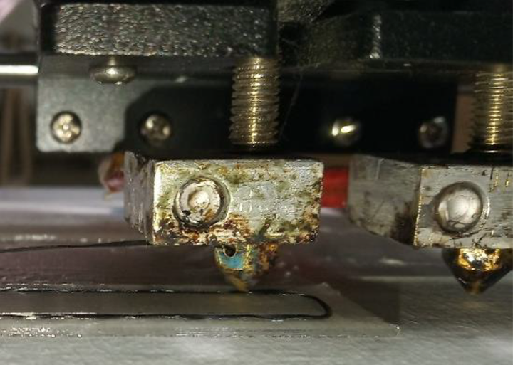
Novel fibre impregnation approach.
In the first step of continuous carbon fibre-reinforced thermoplastic printing, an L9 Taguchi array was employed with three factors each having three levels. After printing and analysing Taguchi array, RSM was used to optimize the parameters for achieving the highest tensile and flexural strength values within the parametric limitations of ASTM and ANET A8-M. A limitation of applying RSM like this, that is, under the limitation of parametric dimensions is that the optimization cannot be extended over the entire range of variables.
Tensile results achieved through Taguchi array indicated an increase in tensile strength of all samples (PLA, ABS and PLA-C) with any thread count as compared to pure thermoplastics. The increase ranged from 1.7 to almost 3 times more. A similar increase in Young’s modulus was also observed. As a general trend, the increase in thread count resulted in the increase in tensile strength while the effect of material followed the same trend as for pure thermoplastics, that is, highest values achieved for PLA and lowest for ABS. It was evident from analysis of Taguchi array the highest contributing factor for tensile strength was thread count while interlayer Gap and Material type had little yet positive impacts (Tables 1 and 2). The impact of ‘material’ was considerably high therefore, for RSM, material factor was excluded and only PLA material was adopted. Hence, it can be concluded that the highest impacting parameters after material are ‘thread count’ followed by a gap.
RSM optimization also yielded similar results with the highest impacting factor being ‘thread count’ for tensile strength. Experimentally an increase of almost 200% was achieved as compared to pure thermoplastic tensile strength. When considering only the increase in tensile strength with ‘thread count’, it was observed that the behaviour is almost linear. Interestingly ‘interlayer gap’ had a slight negative impact. As discussed in the literature review as well, void formations are inevitable in FDM 3D printing and they are one of the major causes of strength decrease. With fibre reinforcement being done in the present research, void formations were also inevitable. Rather with increased thread layup, voids would expectedly also directly increase. However, to conclude, ‘thread count’ still has a high enough impact to counter the negative effect of ‘interlayer gap’.
The coefficients obtained through RSM analysis were employed over the entire range of variables that could theoretically be printed. 3D contour and surface plots were created to better understand the optimization region (Figures 10 and 15). With lower ‘interlayer gap’ and increased ‘thread count’, that is, 1 and 60 respectively; the tensile strength starts to gradually rise. The same happens with lower ‘thread count’ and slightly increased ‘gap’. The last printed specimen of 60 thread at 2-layer gaps had the highest achieved tensile strength lying within the optimum region. It can, therefore, be concluded that within the dimensional limitations maximizing the thread count would positively impact strength increase while the interlayer gap will have a slightly negative impact, therefore, keeping it as low as possible is advised. Eliminating ‘interlayer gap’ completely is not advisable. With a consecutive layer of threads, void formations increase significantly leading to the lowering of strength parameters. It also results in poor surface finish and dimensional inaccuracy. The equations derived from the present research can also be used to predict the behaviour of samples in the design stage using Equation (2) with count-36 and gap-2 as binary 0.
RSM plot for tensile working grid.
In contrast to tensile results, not all thread configurations resulted in flexural strength increase. In the case of PLA, 12 and 24 threads actually resulted in a lowering of strength by almost 0.8 times compared to the bending strength of pure thermoplastic samples. Overall a strength increase behaviour was nevertheless observed with ∼1.5 times increase in case of ABS 36 thread configuration and ∼1.3 for PLA-C. A corresponding increase in flexural modulus has also been observed. Flexural strength increases at the maximum thread count of 36 were highest for ABS followed by PLA-C and PLA. Similar behaviour like tensile was observed as far as the direction of impact is concerned, that is, positive or negative. The impact of ‘Thread count’ was considerably more (17.2 vs. 9.4) for flexural samples as compared to tensile samples. Material also had a huge positive impact. Like Taguchi array results, there were again some configurations that showed a decrease in flexural strength as compared to pure thermoplastic for RSM array. On further scrutiny, it was observed that thread count lower than or equal to 24 resulted, with lower ‘interlayer gap’, in decreased flexural performance. However, overall strength increase was observed with an increase in ‘thread count’ as well as with an increase in ‘interlayer gap’. A fully closed optimized region could not be generated although an open region was found within the boundary of allowed region (Figure 12). The highest flexural strength of 164.09 MPa for a thread count of 60 with a gap of 2 also lies within the same region. The final equation achieved during RSM optimization with a count of 36 and a gap of 2 as binary 0, Equation (3), can be used to predict the impact of ‘thread count’ and ‘interlayer gap’ on bending behaviour.

Rule of mixtures (ROM)
Matsuzaki et al. 19 discussed the reasons for achieving low volume fractions in continuous fibre-reinforced FDM printing. To achieve an automated operation the reinforcing thread has to pass through the nozzle to get impregnated with the thermoplastic so that it can have a direction to be extruded during printing. Such mechanism also ensures continuity in the thread and thus leads to continuously reinforced 3D printed composites. With low clearances between the nozzle and the thread, already a minimal quantity of molten thermoplastic covers the thread which is still able to extrude out of the nozzle. Plus, only a set amount of hatch distance can be lowered while still maintaining enough overlapping between the adjacent layers to ensure maximum pressure build-up that would lead to better mechanical properties. 26 During experimentation it was observed that if hatch distance is further lowered adjacent layers will get jumbled up leading to difficulty in adhesion of subsequent layers, nozzle clogging, thread breakage, warping part and extremely rough surface finish.
Strength increase for the addition of fibre is governed by ROM. 20 With the addition of any amount of fibre the thread volume fraction becomes greater than 0 and should in fact lead to some strength increase. The strength increase continues with an increase in Vf up to a certain extent after which increased thread quantity will result in increased void formations, interlaminar shear and discontinuities in the part. Consequently, if with thread addition there is some increase in the mechanical properties then the Vf is said to be greater than the minimum volume fraction (Vmin) that is required for strength increase. Although there has been very limited research in volume fractions for 3D printed composites Van Der Klift et al. 28 and Namiki et al. 37 have reported 1% achieved volume fraction in their research. In the present research micromechanics analytical calculations 35 have been carried out (Figure 13). Analysing the results, it was observed that the predicted strength values for all the samples based on thread properties (count, etc.) did not consider the effect of ‘interlayer gap’. Because of this, predicted strength values for all the samples containing the same overall count of thread were the same and hence differed considerably from the achieved values.
In all the cases during the present research, strength increase was observed which indicated that the achieved Vf is greater than Vmin. However, it can also be observed that there is not much difference between Vf and Vmin (max −3.59 for PLA 60 thread with a 2-layer gap). This low increase in volume fraction is due to the inherent nature of the FDM process (thread is passed through the nozzle for simultaneous printing). Owing to multiple factors such as nozzle diameter, thread diameter, sample dimensions, thread impregnation and interlayer gap, the thread count will always be limited for FDM processes hence leading to low Vf. An interesting correlation was observed between volume fractions and the strengths both achieved and predicted (Figure 13). As the Vf increased the strength values also increased. This was although an expected result however the exact similarity of visual pattern of Vf with predicted strength and of the minimum required Vf with achieved strength was interesting. In conclusion, it can be said that an increase in Vf leads to an almost corresponding increase in strength. A factor limiting this conclusion is the apparent difference in achieved and predicted values. This can be due to:
ROM formulas assume that the matrix and fibre bonding is perfect leading to uniform load carrying capacity. 35
The testing grip should be with complete friction, that is, no slippage, et cetera.
ROM equations do not take into account interlayer gap(s).
No allowance for random errors such as environmental impacts, part-to-part dimensional variations and operator factors.
Similar to Vf, predicted strength values only depend on the thread count variable and hence samples with the same thread count also had the same value of the predicted strength. The basic premise of ROM equations is that it is not always possible to manufacture all variations of composites to conclude the best results due to many factors such as cost, equipment availability and time constraints. Therefore, a limited number of samples are prepared, and their properties are measured including strengths and Vf. These values are then used to back-calculate certain parameters such as fibre strength and matrix strength. Using these values, the ‘theoretically achievable values of strength’ can now be calculated at other values of Vf as well. However, for this to lead to meaningful analysis the difference should not be considered. Therefore, it is recommended to further study this behaviour of achieved and predicted strength and minimize this gap.
Fracture analysis
During tensile testing following features of fracture were observed that along with Figures 16 and 17 show the brittle nature of samples of present research in line with Thomas-Seale et al. 8 and Chacón et al. 10 :
Fractured tensile specimens.
Fracture analysis.
There is no deformation, that is, no ductile behaviour at the fracture site featured by sharp edges and a flat surface.
Fracture direction is perpendicular to the load applied.
The stress–strain curves lack a definitive yield point rather the failure stress is achieved quite abruptly after the elastic region.
It was observed that fibre generally pulled out of the encasing thermoplastic matrix almost simultaneously with the matrix failure. Similar behaviour of samples was also observed by other researchers.12,17,19,26 In most of the cases, carbon fibre thread did not break off completely. This phenomenon leads to the conclusion that there is a weaker interface between the fibre and thermoplastic. Moreover, voids were also quite clearly visible particularly between two adjacent threads. Low bonding between the samples that results in fibres pulling out of the matrix is the primary reason for low tensile strength. 26 Close inspection of the specimen shows clean fibre coming out of the fractured portions as shown in Figure 17. Although very few fibres were found broken their pulling out in clean, that is, free from encompassing thermoplastic indicates low adhesion between fibre and thermoplastic. It was also observed, as supported by Magalhães et al., 38 Chumaevskii et al. 16 and Van Der Klift etal. 28 that during tensile testing all the samples fractured from within the ‘gage length’ in a plane perpendicular to the force direction but near to the clamps (Figure 16).
To conclude, in the present research the results recorded for continuous carbon fibre-reinforced PLA samples, manufactured through a novel modified nozzle and a dual nozzle setup with increased fibre control, were much higher than pure PLA samples. Moreover, the results obtained are also considerably higher than previous research studies where short fibre-reinforced thermoplastics were 3D printed.13,23,25
Conclusion and future recommendation
The present research aimed to improve upon the works of Tian etal., 26 Nanya et al. 27 and Yang et al. 12 in order to produce mechanically enhanced parts as compared to pure thermoplastics with improved surface finish and better process control. Therefore, a novel thread impregnation approach was designed and implemented where a 1 mm diameter hole at 45° was drilled on side of the nozzle. Carbon fibre thread was successfully passed through it, impregnated with molten thermoplastic, and was extruded out from the 1 mm outlet hole of nozzle. Dual-nozzle extrusion process (one nozzle for thermoplastic covered thread layup and the other nozzle for a pure thermoplastic layup for sample shell printing including bottom, top and sides layers) was adopted which enabled control over volume fraction, deposition rates and amount of thread layup. Mechanical testing was performed, and much improved strengths were achieved for all three thermoplastics reinforced with carbon fibre thread as compared to their pure samples. PLA displayed the best results along with the best surface finish. RSM analysis was done to optimize the thread count and interlayer gap values. Optimization plot and, more importantly, a predicting equation was generated to facilitate future researchers to design their samples and parts to achieve the best possible results. Fracture analysis was also performed along with ROM calculations. Now, despite the success in developing the process, certain limitations and problems were encountered. The strengths achieved by FDM are still much lower and therefore cannot be realistically compared with conventional composite manufacturing methods where a combination of temperature, pressure, chemicals, curing agents and specialized molds are used. However, like in the present research, different methods should be explored to improve the multidirectional (mesh type) thread/fiber orientations, interlaminar strength, layer-by-layer bonding and part surface finish. Thread wetting with some binding agent, heated environment, closed chamber printing and filament pre-processing can be some of the areas that can be explored. Such measures can further 3D printing in mainstream industrial applications.