
Abstract
Determining the interlaminar shear strength (ILSS) of the composite laminates is vital for deciding their usage in any engineering applications. The matrix used and its curing characteristics are vital in deciding the ILSS of the composite. Present work deals with an experimental study on adhesive behavior, degree of flexibility, ILSS, and damage mechanism of the novel jute/rubber-based flexible “green” composite. The proposed flexible composites were prepared in three different stacking sequences, namely jute/rubber/jute (JRJ), jute/rubber/rubber/jute (JRRJ), and jute/rubber/jute/rubber/jute (JRJRJ), using compression molding technique. After determining the optimal curing characteristics of the proposed rubber-based matrix, the constituents are tested for their adhesive strength with the matrix which showed that rubber matrix system is compatible with jute fabric and natural rubber sheet. Composites are prepared and degree of flexibility for each stacking sequence is found out. Results pertaining to ILSS show that JRJRJ has better ILSS compared to JRJ and JRRJ. Fractographic analysis using scanning electron microscope reveals the mode of failure of the composites and the mechanism governing their failure. Fourier transform infrared spectroscopic study reveals the bonding between the constituents is good enough to be used in composites with flexibility.
Introduction
Polymer matrix composites (PMCs) are being widely used in many engineering applications such as aerospace, automobile, marine, sports, and defense due to their advantages over the conventional materials such as metals and alloys. Synthetic fibers such as glass, carbon, and aramid fibers are widely used in the manufacturing of PMCs due to their better mechanical and thermal properties. But, these synthetic fibers are expensive and hazardous to the environment as they are nonbiodegradable. The substitutes for synthetic fibers can be natural fibers which possess advantages such as low cost, ease of availability, and biodegradable/recyclable. They also possess acceptable mechanical, thermal, and chemical properties. Sufficient amount of fibers required for manufacturing the composites can be obtained from the industrial crops grown in abundance and this provides very large scope for using natural fibers.
There are many applications such as secondary and tertiary structures, panels, sacrificial structures where it is not essential for the composite used, to have strong mechanical properties. In such applications, natural fibers can be a potential substitute for synthetic fibers.1,2 Among all the natural fibers available for use, jute fibers seem to be the promising one owing to its better mechanical and thermal properties along with its low cost and ease of availability. Thus, composites based on jute fibers are popularly used in various applications. 3 The main characteristic of any lingocellulosic fiber such as jute is the participation of specific fiber molecular functional groups, which can be analyzed by Fourier transform infrared (FTIR) spectroscopy. 4
Adhesively bonding the constituents of composite has emerged as one of the most promising joining technology since they induce lower stress concentrations compared to conventional fasteners resulting in increased efficiency of the joint in terms of strength-to-weight ratio. 5 The strength and the failure behavior of adhesively bonded structures mainly depend on the mechanical properties of the adhesive material and stress concentration in bonded structures. 6 Adhesives of different types and with a wide range of mechanical properties are available. However, selecting an appropriate adhesive is mainly dependant on the adherend, working environment, and nature of application. 7 In order to evaluate the strength of the adhesive joint and to understand the strength of the adhesive structure, the peel test is considered to be useful. Peel strength can be determined by carrying out the peel test.
Rubberized fabrics have drawn enormous attention and widely used in the textile industry for household, apparel, and furnishing end uses. From an industrial point of view, conveyor belts, inflatable products for marine application, and pipelines for the transfer of materials find the wide application of rubberized fabrics. 8 Nylon and polyester fabrics are more commonly used reinforcements in flexible rubber composites and find their application in hoses, tires, belts, and so on. Adhesion plays a prominent role in ensuring the life of flexible composite. Thus, good bonding is essential between the constituents of the flexible composite.
Natural rubber (NR) mixes usually have good inherent tack and thus added to less tacky materials like synthetic rubbers to enhance their tack property. 9 Numerous scientific literature is published regarding tackifier mediated adhesion between polymers covering different aspects,10–18 but studies involving fabric made of naturally available plant fiber and NR are comparatively less.
Due to the widely accepted and use of PMCs in a variety of engineering applications, proper assessment of mechanical properties of such composites is very essential. Interlaminar shear strength (ILSS) of the composite laminates is one of the important properties that play a vital role in design consideration.19–22 Three factors mainly govern the strength of the PMCs, namely fiber properties, properties of matrix, and interaction between matrix and fiber. The properties of the fiber and matrix can be individually improved, but the interfacial property depends on both matrix and fiber. ILSS is the one that determines the interfacial bonding strength between reinforcement and matrix. 23 The lower value of ILSS is an indication of debonding of fiber from the matrix under the influence of stress which will affect the optimal load transfer from matrix to the fibers. 24
There are two ways to enhance the ILSS of PMCs. The first being modification of fibers25–28 and the second being modification of matrix.29–32 Interleaving method can be used in laminated composites to minimize the interlaminar stresses and improve interlaminar fracture toughness33–36 which results in resisting or arresting delamination. Materials having low modulus and high elongation were made use of as delamination resistors. 37 The material with low surface energy results in possible reduction of surface defects, resulting in higher ILSS. The study carried out by Zhao et al. 38 showed that silicone rubber results in higher ILSS. Nitrile rubber was used to improve the adhesiveness of the composites fabricated using aramid fibers and vinyl epoxy 39 which led to an improvement in adhesion properties of aramid fiber by 44.4%. Though rubber is been used in the modification of matrix and treatment of fibers used in composites to enhance their mechanical properties, the sole role of rubber in improving the mechanical properties of composites remains untouched. The development and few mechanical and tribological characterization of the flexible composites are carried out by Mahesh et al. 40 The ILSS of conventional PMCs/stiff composites which are suitable for primary structural applications is studied by various researchers. However, the study related to ILSS of “green” flexible composites that can be used as a sacrificial structure such as cladding for the bumper of an automobile to protect the primary structure (i.e. bumper) remains untouched till date.
The present study is aimed at determining the optimal cure characteristics of rubber-based matrix, peel strength of the constituents of the flexible composites, degree of flexibility of the proposed composites, ILSS of “green” flexible composite comprising of jute and rubber-based matrix along with interleaving of NR sheets, studying the mechanism, extent and nature of failure of flexible composites and understand the materials used for fabricating the composite and their chemical bonding using FTIR analysis.
Experimentation
Materials
Jute in the form of plain woven fabric (350 GSM and 1450 kg/m3), commercially known as Jute woven cloth, was purchased from the commercial supplier from Haryana, India. NR-based matrix (Bonding gum) and NR sheets (Sun-dried NR sheets) are purchased from Manjunath rubbers Pvt. Ltd., Baikampady, Mangaluru, India. High vacuum silicone releasing agent was purchased from Mahalasa agencies, Mangaluru. The raw materials and chemicals used in the present study were used as received.
Characterization of rubber-based matrix
Proper curing of the rubber-based matrix is very essential during its vulcanization process. The curing and vulcanization of the rubber depends on the temperature and time for which the rubber is subjected to vulcanization. Overheating for longer time leads to “reversion” resulting in deterioration of physical properties of the matrix. Hence, it is very important to determine the exact time and temperature at which the curing of the rubber-based matrix has to be carried out. This temperature and time are known as optimal curing temperature and optimal curing time.
The rubber-based matrix was subjected to compound development and kinetic studies using an oscillating disk rheometer (ODR) according to ASTM 5289-95. About 5 g of the rubber-based matrix was placed in between the disks of the rheometer. The minimum torque (ML), maximum torque (MH), scorch time (tS2), 90% of cure time (tC90), and thermoplasticity (TP) were observed. The optimal curing time and the temperature were found in this study. The cure rate index (CRI) is calculated according to equation (1)
Peel strength characterization
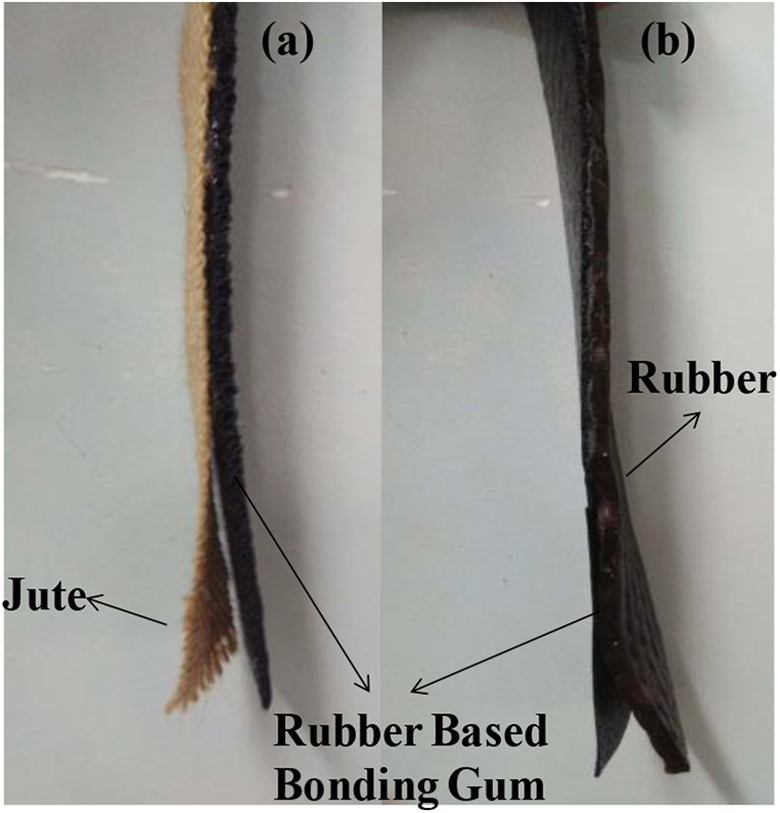
The T-peel specimens required to carry out the peel test are prepared using a compression molding machine by applying temperature and pressure. The jute/rubber is cut and in between the jute/rubber and rubber gum, a separator is placed to get the required opening. The entire arrangement is placed in a compression molding machine under required temperature and pressure. The separator is smeared with silicone releasing agent so that the rubber gum does not bond with the separator. Later, the T-peel specimens are cut to the required dimension (160 mm × 25 mm) as shown in Figure 1. The initial crack created in the T-peel specimen due to the placement of separator is shown in Figure 2.
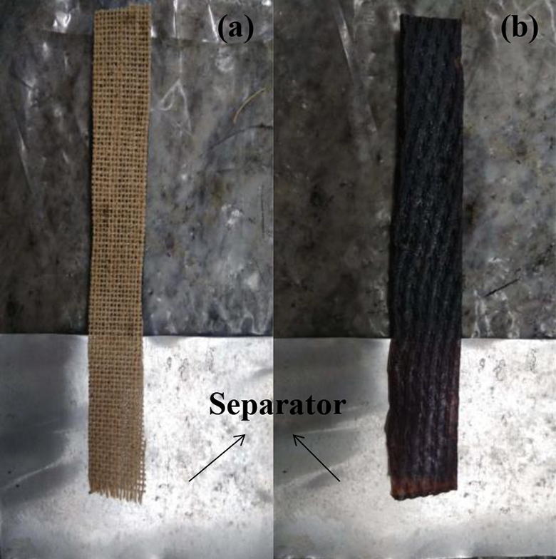
T-peel specimens of (a) jute–rubber gum and (b) rubber–rubber gum.
Initial separations obtained in T-peel specimens.
The prepared T-peel specimens are mounted on the universal testing machine (UTM) with each free end being connected to the fixtures as shown in Figure 3 and the schematic representation of the peel test is shown in Figure 4
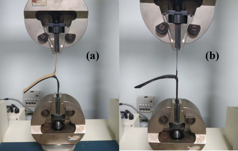
Specimen mounted on UTM.
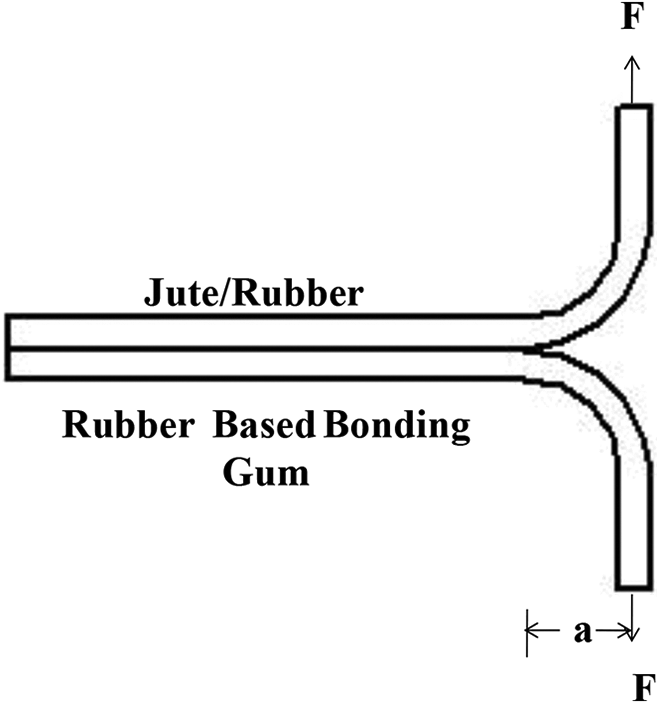
Schematic representation of peel test.
The peel test is carried out using ASTM D413-98 standard to measure the peel strength of the jute fabric and rubber gum; rubber and rubber gum. The force against displacement graph is obtained from the UTM and the peel strength is calculated using equation (2)
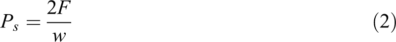
where Ps is the peel strength in N/mm, F is the maximum peel force in N, and w is the width of the specimen in mm. According to modified beam theory, the strain energy release rate (GI) is calculated using equation (3)
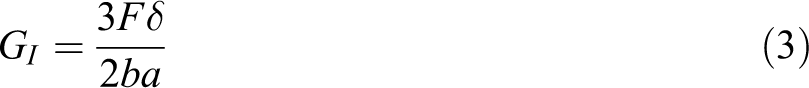
where F is the load, δ is the load point displacement, b is the specimen width, and a is the delamination length (50 mm).
Preparation of composites
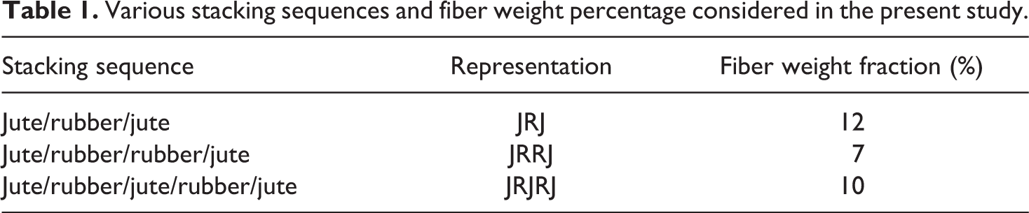
The stacking sequences of the proposed flexible “green” composites considered in the present study along with the fiber weight percentage are given in Table 1 and the schematic of different stacking sequences considered is shown in Figure 5.
Various stacking sequences and fiber weight percentage considered in the present study.
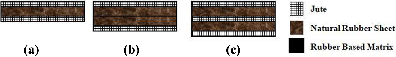
Schematic representation of various stacking sequences. (a) JRJ, (b) JRRJ, and (c) JRJRJ.
The composites were fabricated using a compression molding method with application of heat and pressure (25 kg/cm2). The jute fabric and rubber sheets were cut into the required dimension and arranged as per the required stacking sequence. In between each jute and rubber layers, the rubber-based matrix is placed so as to bond the layers together. A mold of 300 mm × 300 mm with Teflon sheet attached to it was used for compression molding. The layers of Teflon sheet were smeared with silicone high vacuum grease (lab) for easy removal of the composite. The required arrangement of jute and rubber was placed in between the molds and then cured in a compression molding machine as shown in Figure 6(a) at a temperature of 138°C for 7 min as determined from the curing characteristics of a rubber-based matrix using ODR, so that the rubber-based matrix becomes sticky and bonds the layers comprising of jute and NR. Finally, after curing, the composite laminate is obtained as shown in Figure 6(b). Figure 7 shows the schematic representation of preparation and testing of proposed flexible composites considering jute/rubber/jute (JRJ) stacking sequence. The same is applicable for jute/rubber/rubber/jute (JRRJ), and jute/rubber/jute/rubber/jute (JRJRJ).
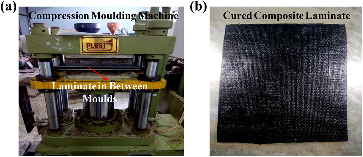
(a) Compression molding machine having laminate in between the mold and (b) cured composite laminate.
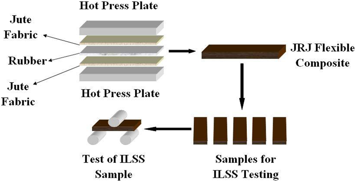
Schematic representation of preparation and ILSS testing of flexible composites.
Flexibility test
The degree of flexibility of the proposed flexible composites is assessed by modifying the two-dimensional drape test used by Lee et al. 41 to measure the flexibility of the shear thickening fluid impregnated fabric composite. The schematic of the test adopted for testing the flexibility of the composites is presented in Figure 8. The flexible composites with stacking sequences JRJ, JRRJ, and JRJRJ were cut into 51 mm × 51 mm and 1 kg weight is then attached to the end of the specimen which resulted in bending angle “θ” of the proposed flexible composite. The effect of thickness on the bending angle is normalized by dividing the bending angle by the thickness.
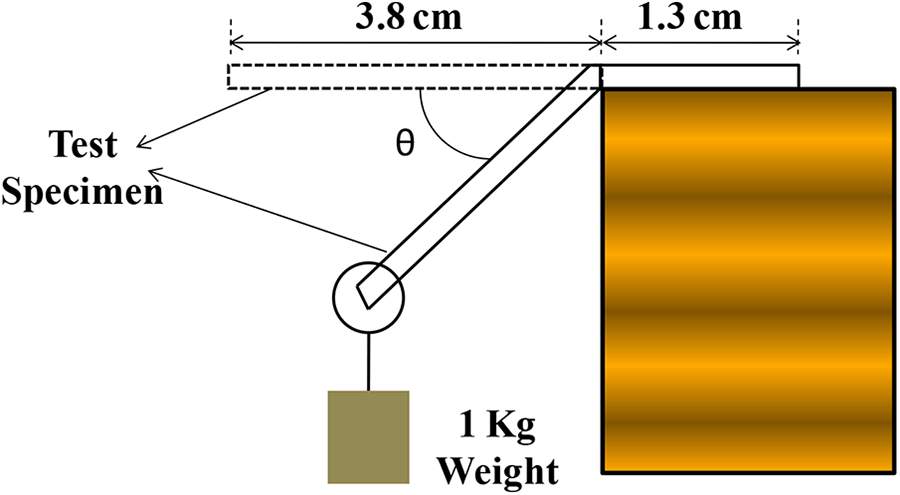
Schematic of flexibility test.
ILSS characterization
Five specimens in each of the stacking sequences are prepared according to ASTM D2344 which is the designated standard for determining the short beam strength of polymer matrix materials and their laminates. The ILSS of the proposed flexible composites was measured using an INSTRON-3366 UTM with a loading capacity of 10 kN at a crosshead speed of 1 mm/min according to standard. Loading nose diameter was 6 mm and supporting rollers were 3 mm each. The span length was maintained at four times the thickness of the specimen being tested. The load against displacement data were recorded from the data acquisition system and the ILSS was calculated using equation (4)

where Fsbs is the short beam strength in MPa, Pm is the maximum load observed during the test in N, b is the measured specimen width in mm, and h measured specimen thickness in mm. The specimens used for ILSS testing and its loading in UTM are shown in Figure 9.
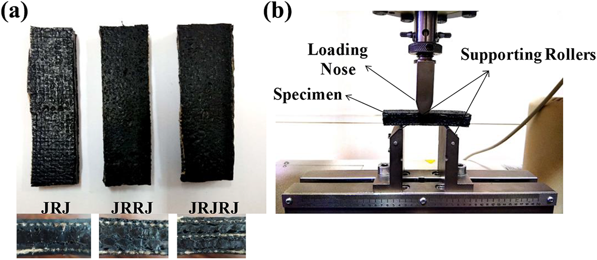
(a) Specimens used for ILSS testing along with its cross section and (b) its loading in UTM.
Scanning electron microscopic (SEM) analysis was used to study the damage mechanism of the flexible composites. Before carrying out the SEM analysis, the damaged specimen is cut and the damaged area which is to be studied is sputtered with gold.
FTIR characterization
FTIR spectrum was obtained for the jute, NR, rubber-based matrix and the flexible composites between 650 and 4000 cm−1 at scanning speed of 2 mm/s using Jasco FTIR-4200, Japan by attenuated total reflection method in order to study the possibility of fiber surface interaction with matrix and rubber surface interaction with matrix. Peaks of FTIR indicate the molecular contributions that permit not only to interpret possible interactions but also to determine the crystalline index.
Results and discussion
Rubber matrix curing
Various kinetic parameters like the order of the cure reaction and rate of reaction were evaluated from the ODR graph of torque versus time as shown in Figure 10. Initially, the compound gets heated up under the pressure resulting in viscosity drop and reducing the torque exerted on the rotor of the rheometer. This lowest value of torque is referred to as minimum torque (ML) which is the measure of the stiffness of uncured rubber compound at a given temperature. The phase up to this stage is referred to as induction and scorch phase.
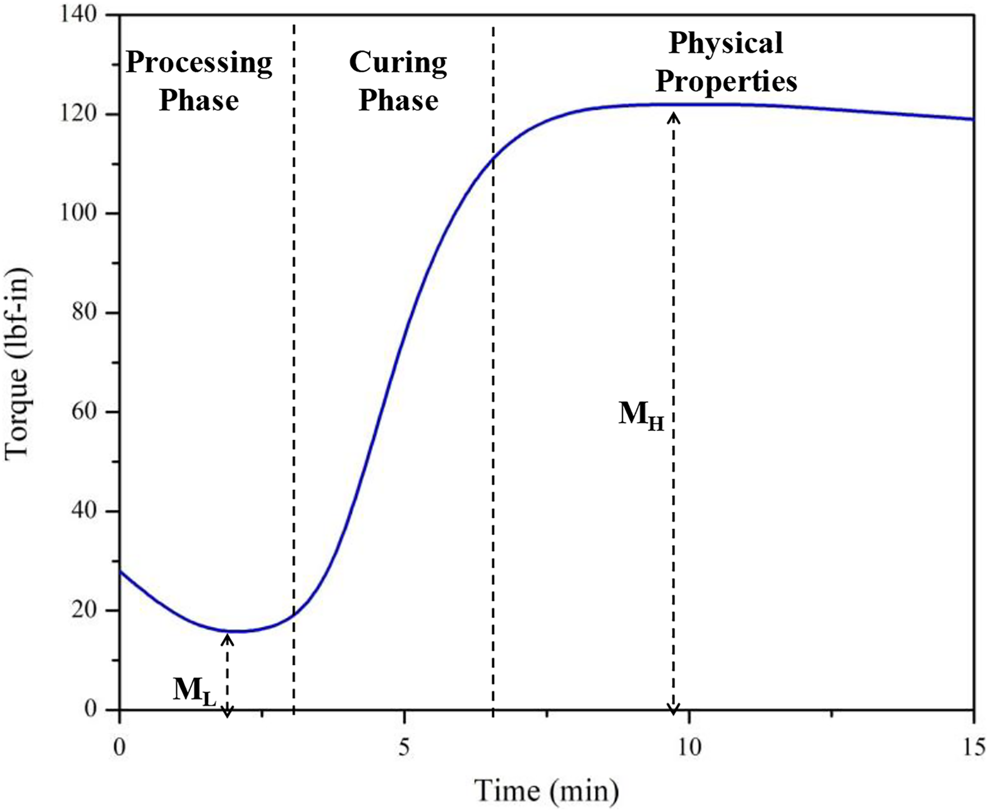
Oscillating disk rheometer graph.
As the curing of the rubber matrix begins, the torque increases and this phase is referred to as the curing phase, at the end of which the rubber matrix will be cured. After the curing phase, the curve attains a stabilized form representing phase that provides the physical properties of the rubber matrix. Over curing in case of NR-based matrix may lead to “reversion” resulting in deterioration of physical properties of the matrix.
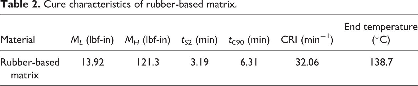
The minimum torque (ML), maximum torque (MH), scorch time (tS2), 90% of cure time (tC90), CRI, and end temperature obtained for the rubber-based matrix sample is provided in Table 2.
Cure characteristics of rubber-based matrix.
Peel strength
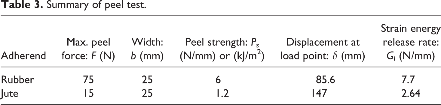
The variation of the peel force against the displacement for jute bonded with rubber gum and rubber bonded with rubber gum is shown in Figure 11. It can be seen that the peel force required to separate the adherend is more in case of rubber bonded to rubber gum compared to jute bonded to rubber gum. This is because of the higher tackiness provided by the rubber which results in more amount of force being needed to separate the rubber from the rubber gum. Table 3 summarizes the results obtained from the peel test. It is found that the peel strength and strain energy release rate of rubber is 5 times and 2.91 times more than jute when bonded with rubber gum.
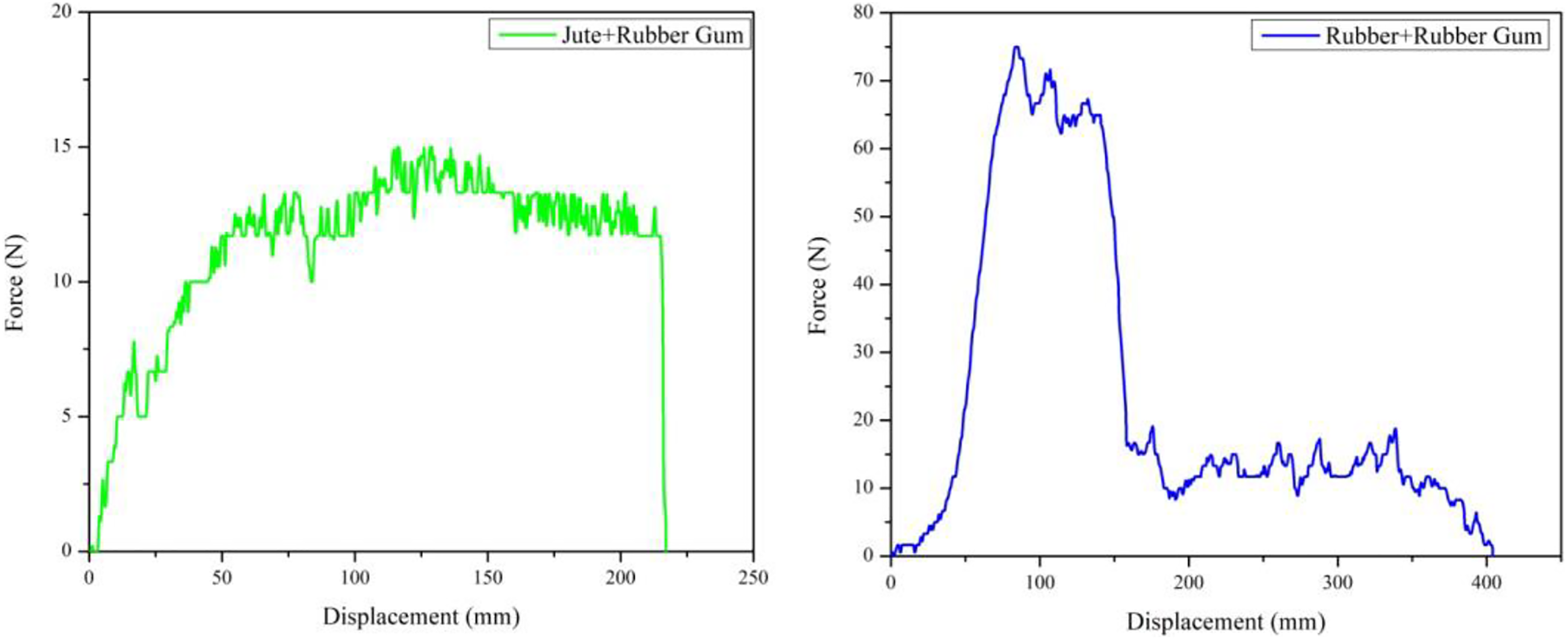
Force versus displacement plot for jute and rubber.
Summary of peel test.
Physical properties
The cross section of the proposed flexible composites is shown in Figure 12. The average values obtained for the density and void content are reported in Table 4.
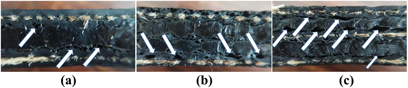
Cross section view of proposed flexible composites showing voids. (a) JRJ, (b) JRRJ, and (c) JRJRJ.
Physical properties of flexible composites.
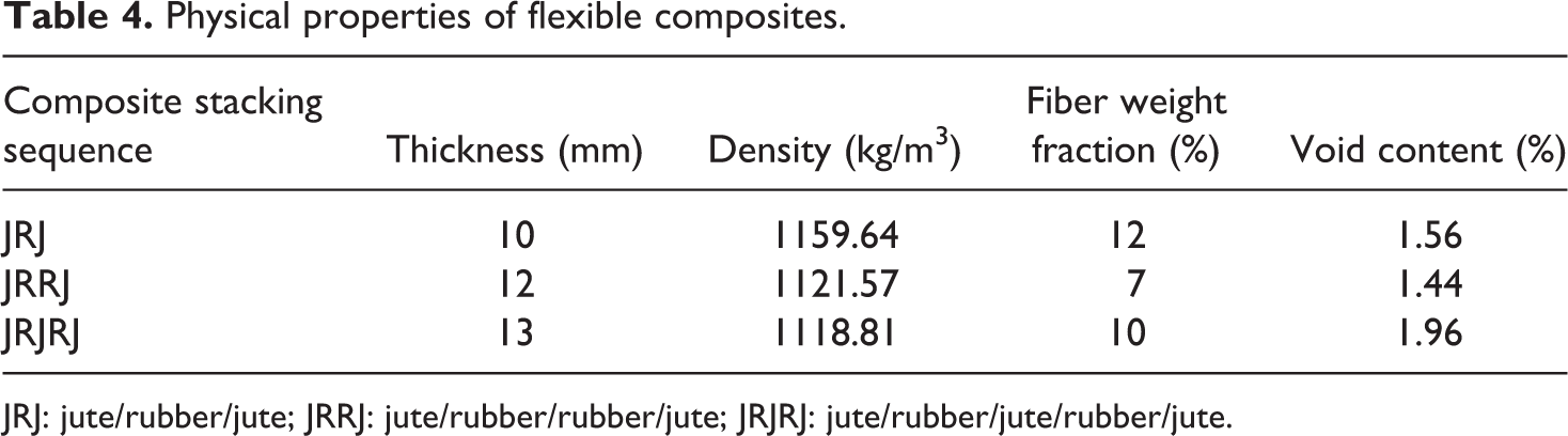
JRJ: jute/rubber/jute; JRRJ: jute/rubber/rubber/jute; JRJRJ: jute/rubber/jute/rubber/jute.
It can be seen from Figure 12 that all the stacking sequences of the proposed flexible composites contain interlaminar voids, whereas the intralaminar voids are absent due to the tackiness of rubber-based matrix. Voids are more in JRJRJ followed by JRJ and JRRJ. This can be possibly due to the nature of the arrangement of plies in the composite. When two similar plies comprising of NR sheets are placed one after the other, better adhesion is achieved between them owing to the tackiness provided by both NR sheet and rubber-based matrix and thus voids are reduced. However, placing jute and NR alternatively enhances the void content, especially with an increase in the number of plies. Voids, in general, are considered as imperfections in composites having detrimental effect on ILSS, flexural, compressive, fatigue, and fracture toughness properties. 42 Increase in fiber weight percentage leads to improved ILSS and flexural strength of composites. 43 Thus, it is clear that the ILSS of the composite depends on the void content and fiber weight percentage. Increase in void content reduces the ILSS, whereas increase in fiber weight percentage increases the ILSS. In the proposed flexible composite with different stacking sequences, both void content and fiber weight percentage vary among the stacking sequences. Hence, the combination of void content percentage and fiber weight percentage contributes in deciding the ILSS of the proposed flexible composites. JRJRJ has highest void content followed by JRJ and JRRJ. However, JRJ has highest weight percentage of fiber (12%) followed by JRJRJ (10%) and JRRJ (7%). Though JRJRJ has the highest percentage of void content (1.96%), the presence of 10% of fiber by weight fraction results in enhanced ILSS of JRJRJ compared to its counterparts.
Also, even though JRJ has highest fiber weight percentage of 12%, the presence of void content percentage of 1.56% leads to reduced ILSS. JRRJ has lowest void content percentage (1.44%) which should have resulted in the highest ILSS. But, the presence of less fiber weight percentage (7%) results in JRRJ exhibiting intermediate ILSS compared to JRJ and JRJRJ.
Flexibility
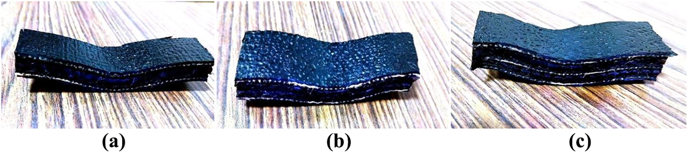
The flexibility of proposed flexible composites can be realized from Figure 13 where outstanding flexibility is exhibited by the composite through large deflection. There was also no indication of crack on the composite surface. This is an indication of the higher flexibility of the proposed composite as opposed to the conventional stiff composites. This also means that the stiffness of the proposed flexible composites is less.
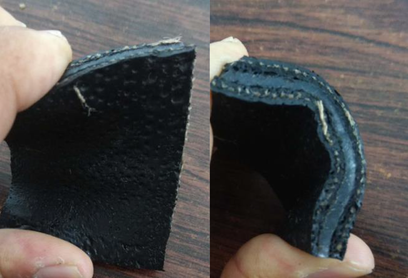
Photograph demonstrating the flexibility of the composite.
The results pertaining to the flexibility tests are presented in Table 5. It can be seen that the variation in thickness of the flexible composites is minimal. However, the flexibility of flexible composites varies significantly. Among the three different stacking sequences considered, JRJ is more flexible with a bending angle of 45° followed by JRRJ (25°) and JRJRJ (22°). The flexibility of JRJ is 1.8 and 2.04 times more compared to JRRJ and JRJRJ which helps it to absorb more energy compared to the other two stacking sequences. Introduction of an additional layer of rubber leads to reduced flexibility restricting the deformation and energy absorption capability of the flexible composite and enhancing its coefficient of restitution (CoR). There is no much variation in bending angle of JRRJ and JRJRJ indicating their flexibility is almost same and the addition of an extra layer of jute reduces the flexibility by mere 3°. This shows that the flexibility or the bending angle of the proposed flexible composites depends on the thickness of the composite and the effect of the thickness on flexibility of the composite when same constituents are used cannot be altered. This is due to the fact that with addition of each layer to the composite, the stiffness of the composite gets enhanced and thus results in reduced flexibility. However, the effect of the thickness on the bending angle is nullified by normalization technique where the bending angle is divided by the thickness of the composite. This helps in comparison of the flexibility of the composites. Larger the normalized angle, larger is the flexibility. The normalization values indicate that flexible composite with JRJ stacking sequence is more flexible followed by JRRJ and JRJRJ.
Flexibility test results.
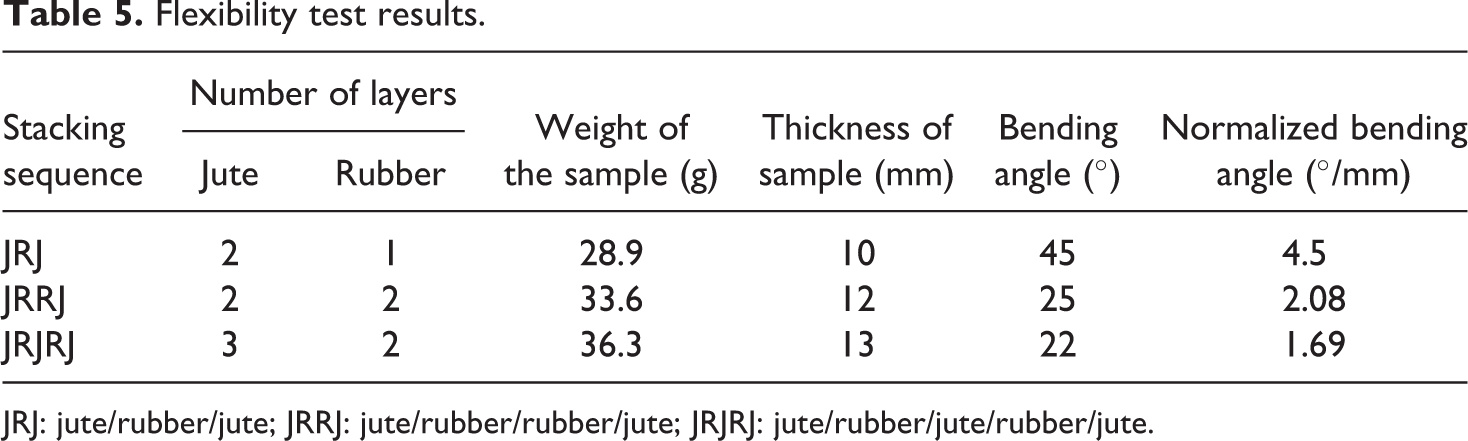
JRJ: jute/rubber/jute; JRRJ: jute/rubber/rubber/jute; JRJRJ: jute/rubber/jute/rubber/jute.
A simplified model as shown in Figure 14 is employed to illustrate the effect of jute fibers on the rubber matrix during the bonding of jute with the rubber matrix. Since woven jute is used, there exists a gap between each yarn while weaving the jute fabric. While binding the jute and the rubber-based matrix, due to capillarity action, the rubber-based matrix will entrap and shrink in the gaps of the woven jute and moves towards the contraction center at the center of the lamina. Due to the adhesion of the jute with the rubber, the adhesive forces will be developed. As the matrix undergoes shrinkage, it gets contracted towards the center and thus the center has to conquer the adhesive forces between jute fiber and the rubber-based matrix and the resistance from the introducing jute fiber. To be more specific, as represented in Figure 14 for the case of in the plane lamina, the adhesive forces and the resistance can be conveniently divided into tensile stress (σi1) and thrust (σi2) produced by the fibers along with the shear stresses (τi1 and τi2) induced by the fibers, respectively. When out of lamina plane is considered, adhesive forces corresponding to four shear stresses (τc1, τc2, τc3, and τc4) between jute fiber and the rubber is the main reason for resistance along with the thickness. The shrinkage of the rubber-based matrix is hindered by these resistive forces. More fiber content results in the crowded matrix and thus increases the resistance thereby contributing to resistance in volume shrinkage. In brief, it is the adhesive and thrust forces that restrict the rubber matrix to shrink and move. Due to this reason, the proposed jute/rubber composite has less volume shrinkage and forms the structure foundation of the flexibility. Thus, the flexibility of the proposed composites is enhanced.
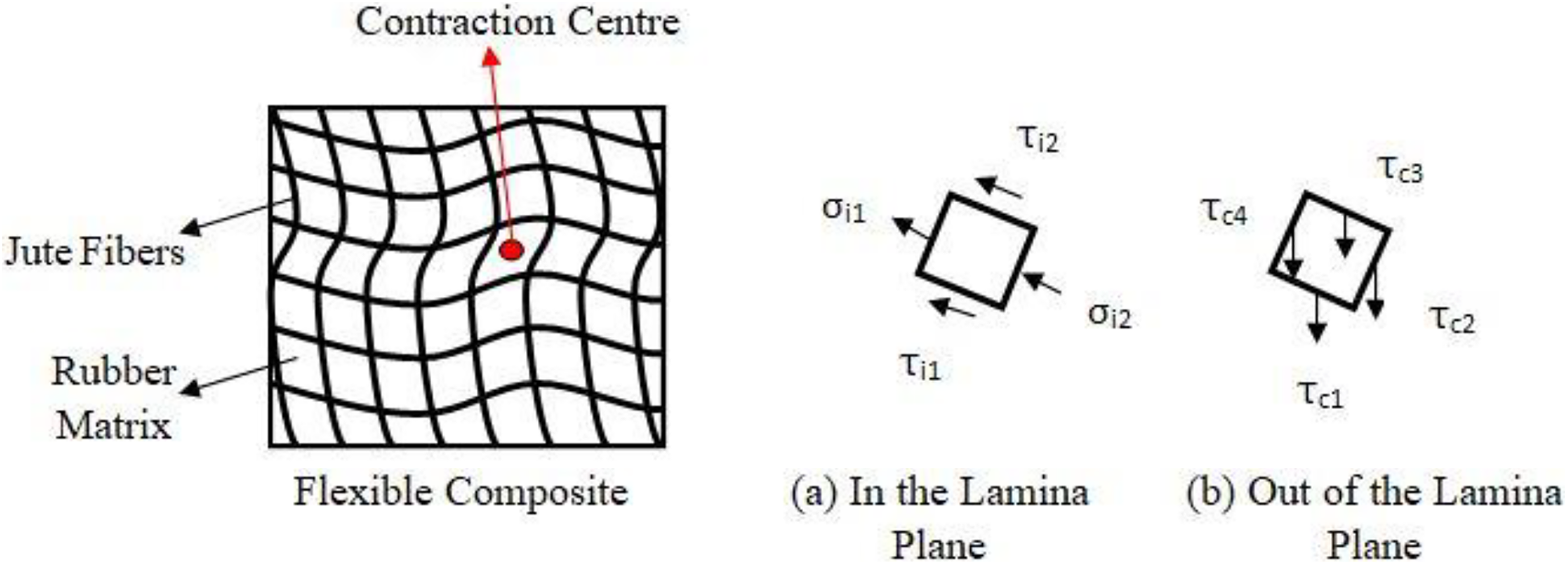
Idealized model for composites and force analysis of the matrix unit.
ILSS characterization
Due to the difference in the dimensions of the specimen, the force–displacement curves of each flexible composite can only be used to represent the load-carrying behavior with respect to displacement and cannot be used to compare the ILSS of the flexible composites. In order to facilitate the comparison of ILSS of the proposed flexible composites, the methodology adopted by Wang et al. 44 is used, where the loads on the specimen are converted to ILSS using equation (4) and the normalized deformation by displacement/thickness was adopted to represent the deformation of each type of sample.
Table 6 provides the average results obtained from the ILSS testing of proposed flexible composites.
Average experimental ILSS values of flexible composites.
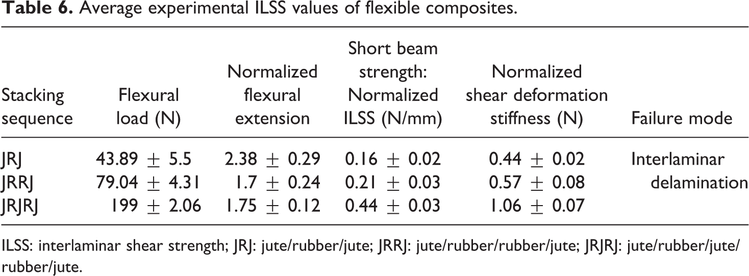
ILSS: interlaminar shear strength; JRJ: jute/rubber/jute; JRRJ: jute/rubber/rubber/jute; JRJRJ: jute/rubber/jute/rubber/jute.
Short beam strength (SBS) test is used to measure the ILSS of proposed flexible composites. It is not necessary that in SBS the specimen will fail by pure shear.45–47 Figure 15 shows the normalized ILSS for the proposed flexible composites variants (JRJ, JRRJ, and JRJRJ) considered in the present study.
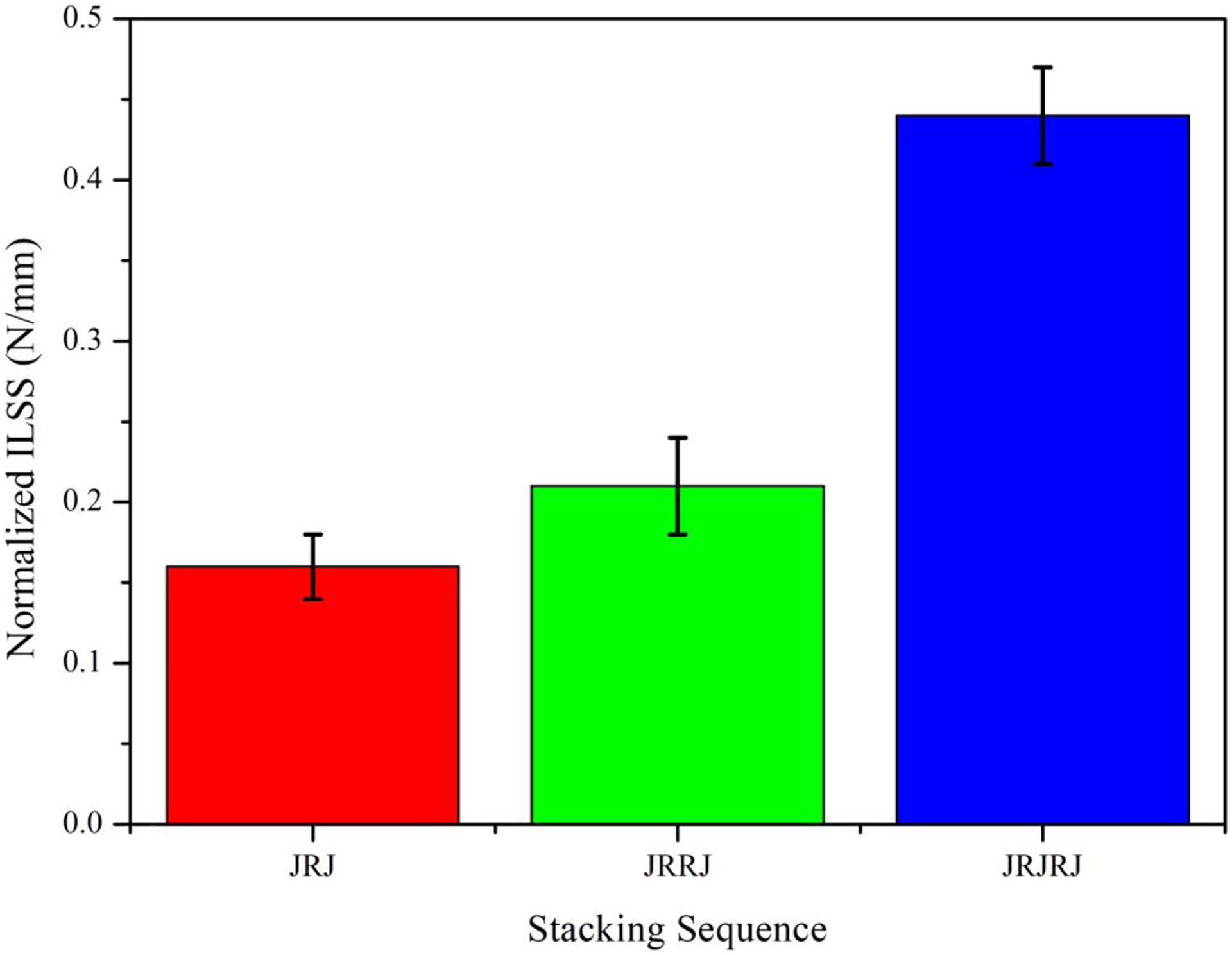
Variation of normalized ILSS for flexible composites.
Comparing the load-carrying capability, it can be seen that the flexible composite variants have a load-carrying capacity in the order JRJRJ > JRRJ > JRJ. This is due to the fact that in the case of JRJRJ, there are three layers of reinforcement used as opposed to JRJ and JRRJ which enables it to withstand more load compared to JRJ and JRRJ. Also, considering the void percentage in the composites, it can be said that there is no much variation in the void percentage and the combination of void content, fiber weight percentage along with thickness determine the load-carrying capability of the composites.
In case of flexible composites, unlike stiff composites, the presence of voids does not lead to matrix cracking and thus void content is not that significant in determining the strength of the flexible composites. The load-carrying capacity of JRRJ compared to JRJ is better due to the interleaving of two layers of NR sheet as compared to one in case of JRJ. It is observed that the ILSS of the proposed flexible composites ranges from 0.16 to 0.44 N/mm. The maximum ILSS of the composite is obtained for stacking sequence of JRJRJ with an increase in 2.75 and 2.09 times compared to JRJ and JRRJ. This result indicates that ILSS of flexible composites depends mainly on thickness apart from fiber and void content. The plots of load versus displacement for all the three flexible composites make it clear that the flexible composites are subjected to “homogeneous shear.” 46
The variation of normalized stiffness and normalized displacement for different stacking sequences of flexible composites are presented in Figure 16. The slope of the load versus displacement curve represents the shear deformation stiffness. It can be seen that JRJRJ exhibits the highest normalized shear deformation stiffness followed by JRRJ and JRJ. The normalized shear deformation stiffness of JRJRJ is 2.4 and 1.85 times more compared to JRJ and JRRJ. The stiffness of the flexible composites varies in the order JRJRJ > JRRJ > JRJ. This is due to the obvious fact that JRJRJ has more number of layers and higher thickness compared to JRRJ and JRJ resulting in higher stiffness. Similarly, JRJ having a minimum number of layers and thickness yields lower stiffness and higher flexibility.
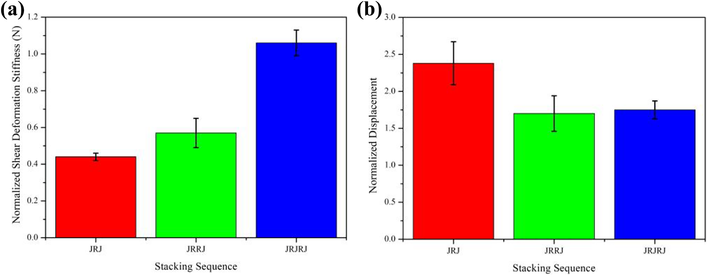
Variation of (a) normalized stiffness and (b) normalized displacement for different variants of flexible composite.
The normalized short beam displacement values for different variants of the flexible composite are presented in Figure 16. It can be seen that the normalized displacement varies from 1.7 to 2.38 with JRJ having higher displacement prior to failure followed by JRJRJ and JRRJ. The normalized displacement of JRRJ is found to be 28.57% and 2.85% lower than JRJ and JRJRJ. The interlaminar delamination failure at the neutral axis led to the limited displacement of the JRRJ flexible composite compared to JRJ and JRJRJ.
In order to establish that the ILSS obtained for different stacking sequences are statistically different from each other, one-way analysis of variance (ANOVA) is applied to the obtained results at 95% confidence level (α = 0.05) as shown in Table 7 along with their mean and standard deviation values. Since the p value obtained from one-way ANOVA is less than 0.05, it can be concluded that the results obtained are significantly different statistically.
Mean, standard deviation, and ANOVA results.
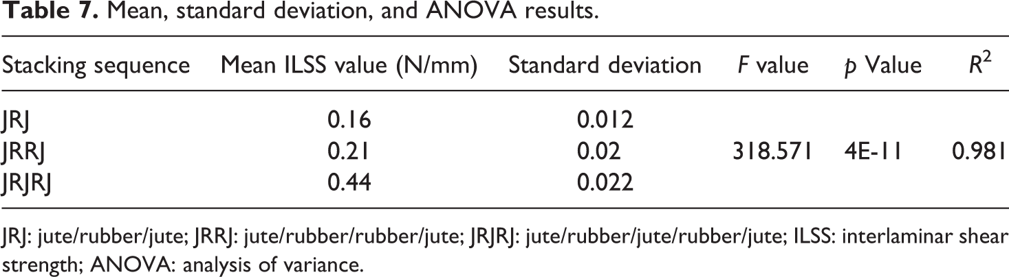
JRJ: jute/rubber/jute; JRRJ: jute/rubber/rubber/jute; JRJRJ: jute/rubber/jute/rubber/jute; ILSS: interlaminar shear strength; ANOVA: analysis of variance.
Failure modes and mechanism
The different modes of failure as recommended by ASTM D2344 standard are presented in Figure 17 which can be regarded as a valid failure to evaluate interlaminar shear properties.
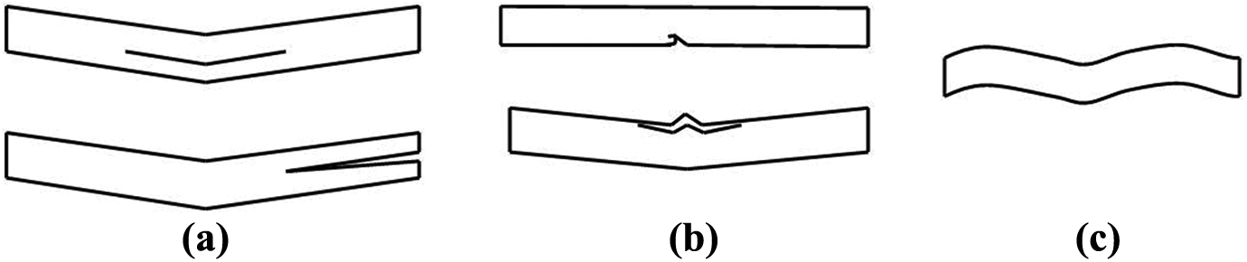
Modes of short beam failure recommended in ASTM D2344: (a) interlayer shear, (b) flexure, and (c) inelastic deformation.
The specimen under test is shown in Figure 18 and Figure 19 shows the damaged samples after the test which confronts to the flexure type of damage as recommended in ASTM D2344. The nature/pattern of damage and the areas of damage for each variant of flexible composites are shown in Figures 20, 21, and 22 for JRJ, JRRJ, and JRJRJ, respectively.
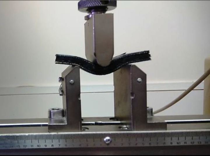
Specimen under test.
Failed samples of (a) JRJ, (b) JRRJ, and (c) JRJRJ.
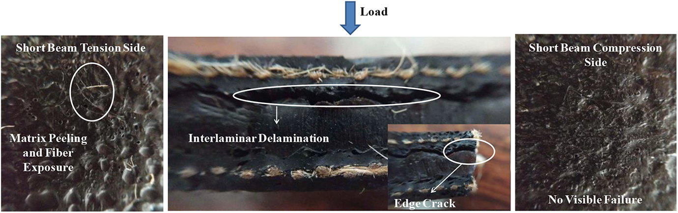
Short beam failure pattern of JRJ.
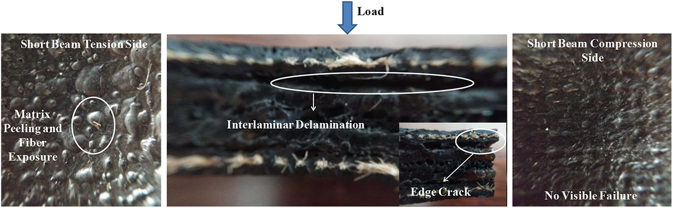
Short beam failure pattern of JRRJ.
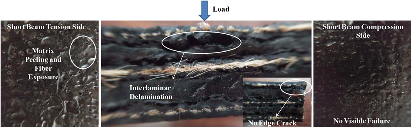
Short beam failure pattern of JRJRJ.
The proposed flexible composite when subjected to three-point loading experiences both tension and compression. The top surface of the sample experiences compression and the bottom surface experiences tension. Side of the short beam sample experiencing tension undergoes outward lateral deformation leading to peeling of matrix and minimal fiber exposure. However, this is not the case with the side of the short beam experiencing compression and no visible macro damage was observed on the surface of the structure experiencing compression. In flexible composite with JRJ and JRJRJ stacking sequences, separation of the layers leading to delamination can be observed due to shear loading, and since the neutral axis passes along the NR sheet in case of JRJ and along jute layer in JRJRJ, there is no shear failure observed along the neutral axis for both the stacking sequences. However, in case of the flexible composite with stacking sequence, JRRJ along with the separation of the layers failure at the neutral axis is also found. Also, it is found that the crack at the edges is found only in JRJ and JRRJ stacking sequences and no edge cracking is found in JRJRJ. This may be possibly due to the thickness of the stacking sequence and insertion of second jute layer in between, which helps in resisting the shear by taking more load and thereby avoiding edge cracking.
It can be seen from the figure that there is no complete separation of the samples into two pieces and they exhibit resistance to shear loading due to flexible nature of the composites and due to better and stronger interlaminar bonding produced during curing. The void content, position, and size of voids in the composites affect the interlaminar and flexural properties of the composites. In the proposed flexible composites, the voids were concentrated near the interfaces between the laminates resulting in failure of load transfer across the thickness of the composite and hence resulted in delamination of the composites at weaker interlaminate interfaces.
The variation of delamination length and ILSS for varying stiffness is shown in Figure 23. In the proposed flexible composites, the normalized stiffness of JRJ, JRRJ, and JRJRJ are found to be 0.44 N. 0.57 N, and 1.06 N respectively. JRJRJ stacking sequence with the stiffness of 1.06 N has normalized minimum delamination of 1.07 and highest normalized ILSS of 0.44 N/mm followed by JRRJ with normalized delamination of 2.91 and normalized ILSS of 0.21 N/mm and JRJ with normalized delamination of 4.3 and normalized ILSS of 0.16 N/mm.
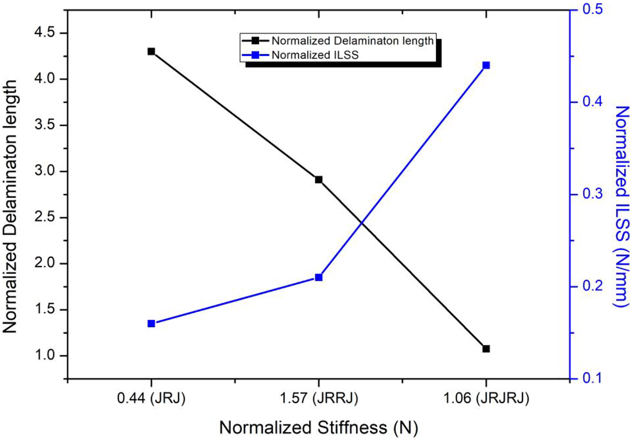
Variation of the length of delamination and ILSS with varying stiffness.
SEM analysis
The rubber-based matrix used in the present study and its SEM micrograph is shown in Figure 24. Figure 25 shows peel traces of jute on rubber gum and tearing of rubber sheet from the rubber gum during a peel test. Good interfacial compatibility enabled more fibers being embedded in the rubber gum, which was demonstrated by more and deeper marks left after the fibers are pulled out. The grooves left out by fibers might be considered as the embedding patterns or the pullout traces. In case of peeling of rubber sheet from the rubber-based gum, stretching and tearing of the rubber can be seen leading to higher peel force and subsequently higher peel strength compared to peeling of jute from rubber gum.
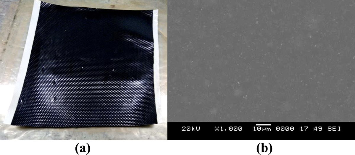
(a) Rubber-based matrix used in the present study and (b) its SEM micrograph.
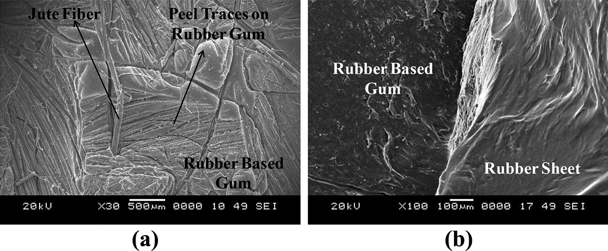
(a) Peel traces of jute fiber on rubber gum and (b) tearing of rubber and rubber gum.
The fractographic analysis of flexible composites subjected to short beam shear test is shown in Figure 26. It is clear from the SEM analysis that shear forces lead to interlaminar delamination between the laminates. It was also found that the bonding between jute fibers and the rubber-based resin is very strong as most of the fibers are impregnated into rubber surface without being separated from one another, although a very little amount of fiber pullout is evident. The reason behind this better adherence could be diffusion of rubber-based resin to jute surface and interleaved rubber sheets, creating mechanical locks.
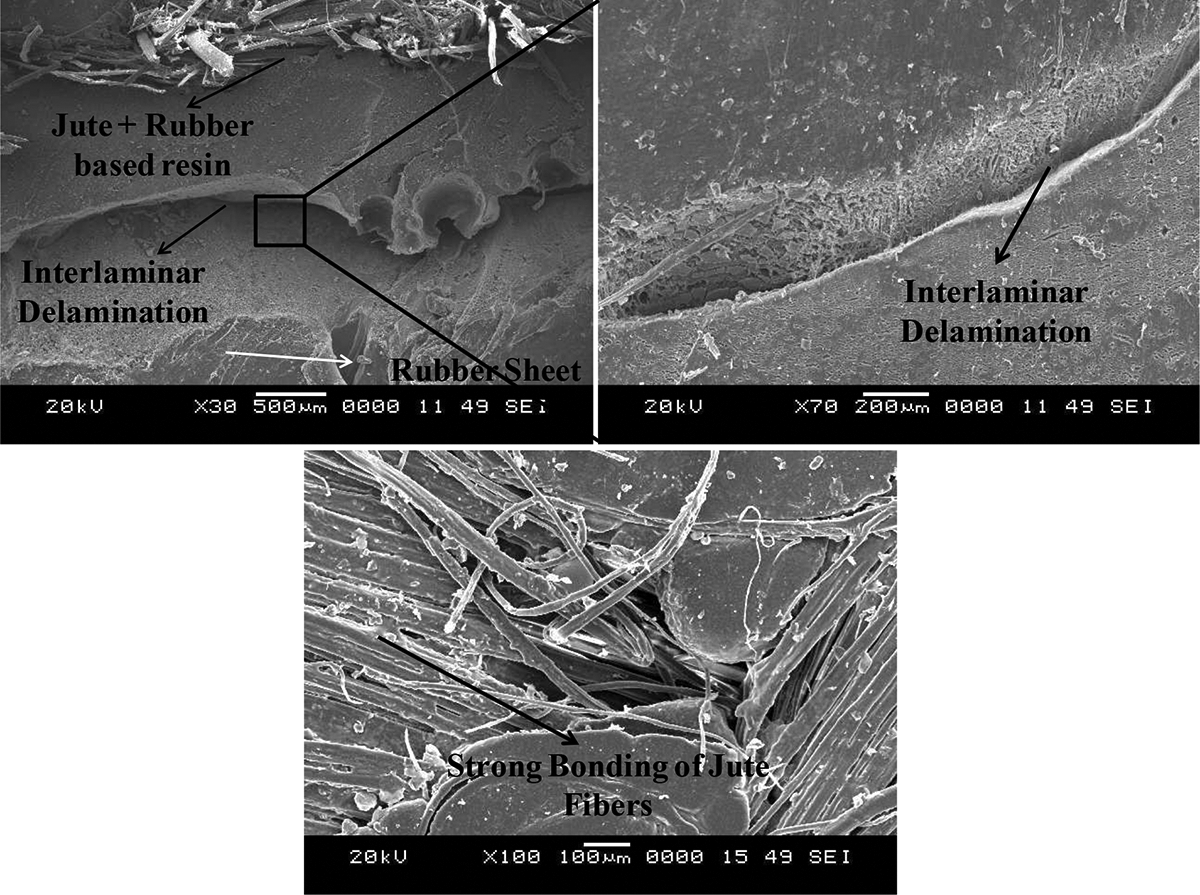
Fractographic analysis of flexible composite.
No evidence of matrix cracking as found in conventional stiff composites is found in the proposed flexible composites; instead, the delamination occurs due to debonding of the layers at the interlaminar region. This is the different mechanism observed in flexible composites where delamination happens without matrix cracking or fiber breakage and possibly due to transfer to shear load to the interlaminar region.
FTIR characterization
FTIR spectra of the jute fiber used in the present study are shown in Figure 27(a). From the FTIR of jute, it is clear that jute contains a large number of oxygenous functional groups. Different absorption bands can be observed in the spectra from 650 to 4000 cm−1. The absorption band at 3335.28 cm−1 is due to hydroxyl (OH) stretching vibration. This stretching may be associated with absorbed water. The absorption band at 2920.66 and 2851.24 cm−1 is due to CH2 and CH3 stretching indicating a characteristic of the organic molecular structure of any natural fiber.
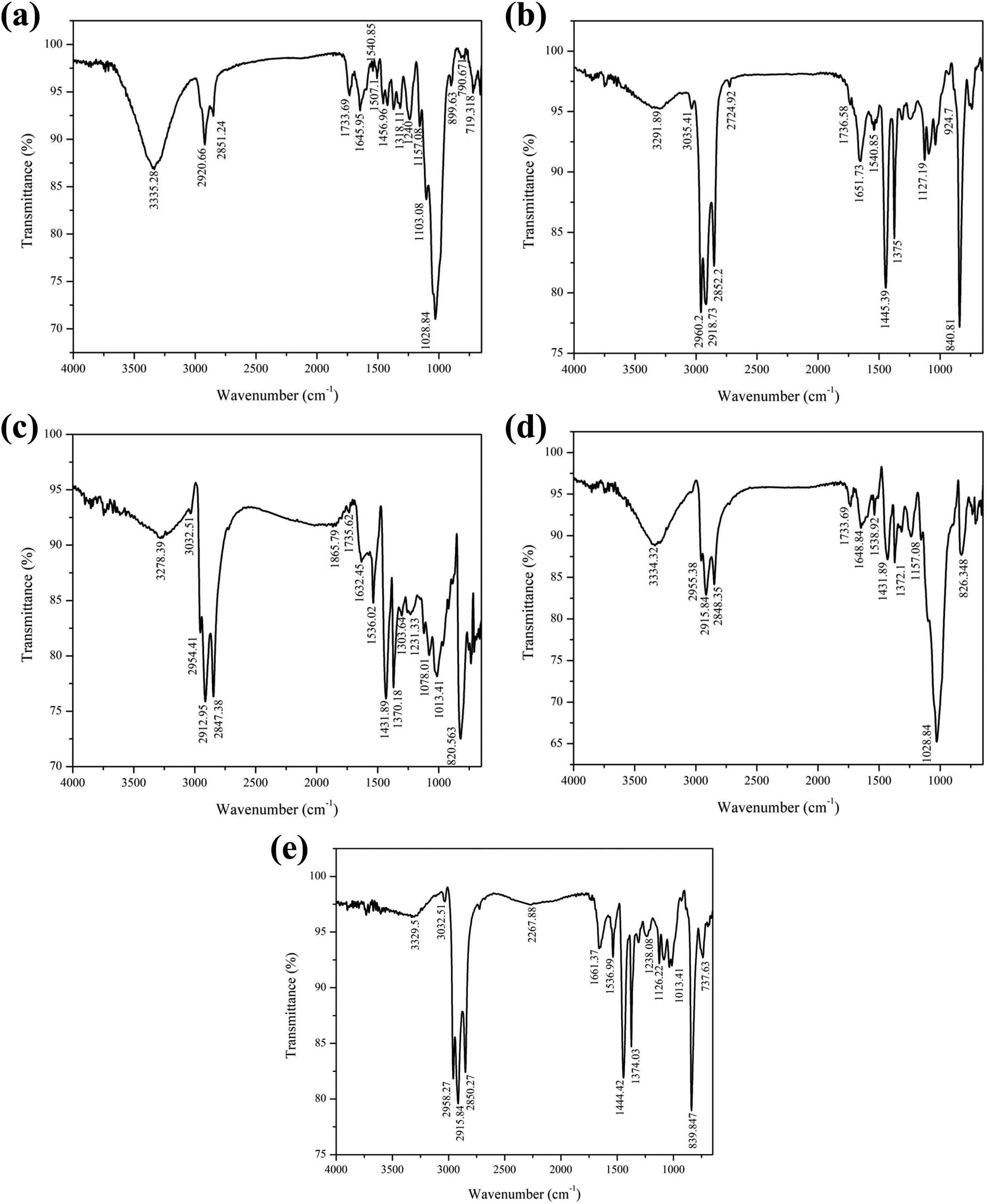
FTIR spectra of (a) jute, (b) NR, (c) rubber matrix, (d) jute + rubber matrix, and (e) NR + rubber matrix.
Bands at 1733.69 cm−1 may be due to C=O stretching. Bands in these regions can be attributed to vibration of alpha-keto carbonyl for cellulose. The band at 1645.95 cm−1 is obtained due to H–O–H bending of absorbed water. It can be observed that the bands corresponding to benzene ring stretching are very small ranging from 1540.85 to 1507.1 cm−1. The band 1456.96 cm−1 corresponds to CH2 bending in lignin and the band 1421.28 cm−1 represents CH2 and CH3 bending. The bands 1327.1 and 1318.11 cm−1 are due to CH2 wagging (lignin) and 1240 cm−1 is due to C–O stretching of acetyl (lignin). The band 1157.08 cm−1 occurs due to C–O–C antisymmetric bridge stretching in cellulose and hemicelluloses. Band 1103.08 cm−1 represents O–H association in cellulose and hemicellulose. The appearance of absorption band 1028.84 cm−1 is a result of C–O stretching in cellulose, hemicelluloses, and lignin. The FTIR bands obtained reveals that untreated jute fiber used in the present study is prone to suffer decomposition by reacting with alkaline and acid solutions. Also, molecular bonding may be formed with polymeric matrices in composites.
The FTIR spectra of NR and rubber-based matrix shown in Figure 27(b) and (c), respectively, indicates weak hydrogen bond absorption at bands 3291.89 and 3278.39 cm−1. It can be seen from Figure 27(d) that the composite obtained from binding of jute to rubber-based matrix provides stronger hydrogen bonding at 3334.32 cm−1 compared to rubber-based matrix alone. Similarly, from the FTIR spectrum of the composite obtained from binding NR to rubber-based matrix as shown in Figure 27(e) indicates better hydrogen bonding at 3329.5 cm−1. However, the hydrogen bonding of NR plus rubber-based matrix composite is slightly weaker than that of jute plus rubber-based matrix composite.
The stretching of N–H proteins in case of NR and rubber-based matrix happens at 3291.89 and 3278.39 cm−1, respectively. However, in case of jute plus rubber-based matrix composite and NR plus rubber-based matrix composite, the same happens at 3334.32 and 3329.5 cm−1. The stretching of C=C–H in case of NR and rubber-based matrix is found to occur at a wavenumber of 3035.41 and 3032.51 cm−1 which is further reduced in case of jute plus rubber-based matrix composite to 2954.51 cm−1. However, it remains the same for NR plus rubber-based matrix composite.
Conclusion
In the present work carried out, the ILSS of “green” flexible composite obtained by reinforcing jute fibers in a rubber-based flexible matrix with interleaving of NR sheets was studied experimentally and following conclusions are drawn: It was found that the curing of the rubber-based matrix happens at a temperature of 138.7°C and at time of 6.31 min. The adhesive study revealed that the rubber matrix system is compatible with jute as it provides good interfacial compatibility by demonstrating more and deeper marks left after the fibers are pulled out. Considering the compatibility with the rubber sheet, it is found that the peel strength is much higher than the peel strength with jute as higher peel force is required to separate the rubber from the rubber matrix. It is found that the peel strength and strain energy release rate of rubber is 5 times and 2.91 times more than jute when bonded with rubber gum due to the higher tackiness provided by the rubber which results in more amount of force being needed to separate the rubber from the rubber gum. The flexibility of the proposed composites is enhanced since the jute fiber bears the tension and delivers the external stress to other parts of the composite thereby avoiding stress concentration resulting in the distribution of stress over the entire composite without inducing intralaminar material failure. The flexibility test indicates that JRJ is more flexible followed by JRRJ and JRJRJ enabling it to absorb more energy. The flexibility of JRJ is 1.8 and 2.04 times more compared to JRRJ and JRJRJ. This shows that the introduction of an additional layer of rubber leads to reduced flexibility and thereby enhancing CoR. There is no much variation in bending angle of JRRJ and JRJRJ indicating their flexibility is almost same and the addition of an extra layer of jute reduces the flexibility by mere 3°. Load carrying capacity of proposed flexible composites vary in the order JRJRJ > JRRJ > JRJ indicating that JRJRJ is less prone to damage compared to JRJ and JRRJ. Higher ILSS of JRJRJ results in higher load requiring for causing smaller delamination. Whereas, lower ILSS of JRJ causes delamination at lower load. Adoption of NR sheets and the addition of fiber enhance the ILSS of the flexible composites. Maximum ILSS is obtained for stacking sequence of JRJRJ with an increase in 2.75 and 2.09 times compared to JRJ and JRRJ. It was found that ILSS of flexible composites does not only depend on the void content and fiber weight percentage but also depends on the thickness of the laminate. The normalized displacement of JRRJ is found to be 28.57% and 2.85% lower than JRJ and JRJRJ indicating that JRJ is more flexible followed by JRRJ and JRJRJ and thus JRJRJ is stiffer compared to its counterparts. Normalized shear deformation stiffness of JRJRJ is found to be 2.4 and 1.85 times more compared to JRJ and JRRJ. The interlaminar failure at the neutral axis led to the limited displacement of the JRRJ flexible composite compared to JRJ and JRJRJ. The short beam failure behavior on the tension and compression side of the flexible composite exhibited the same pattern for all the variants with no visible failure on the compression side and matrix peeling with minimal fiber exposure on the tension side. However, in case of flexible composite with JRJ and JRJRJ stacking sequences, separation of the layers was observed due to shear loading and in case of JRRJ stacking sequence, in addition to the separation of layers, failure at neutral axis was also found. The damage study of the proposed flexible composites shows that there is no complete separation of the samples into two pieces which is an indication of proposed flexible composites exhibiting resistance to catastrophic failure due to shear loading. No evidence of matrix cracking is found in the proposed flexible composites; instead, the delamination occurs due to debonding of the layers at the interlaminar region with a mechanism completely different from conventional stiff composites with delamination happening without matrix cracking or fiber breakage and possibly due to transfer to shear load to the interlaminar region. It was revealed that insertion of additional jute layer in between helps in resisting the shear and taking more loads, thereby avoiding edge cracking. It was found that the stiffness of the flexible composite is inversely proportional to delamination length and directly proportional to ILSS of flexible composites. FTIR study reveals that untreated jute fiber used in the present study is prone to suffer decomposition by reacting with alkaline and acid solutions. Also, molecular bonding may be formed with polymeric matrices in composites. This indicates that the proposed flexible composite is completely biodegradable and falls into the class of “green” composite. Also, the addition of jute and NR to the rubber-based matrix results in better chemical properties compared to matrix alone.