
Abstract
Hybrid material systems, where two materials with similar melting temperatures are combined to form a new compound, represent a possible avenue to expand the materials palette available for 3-D printing platforms such as fused deposition modeling (FDM™). In general, the morphology of filler materials in thermoplastic composites is unchanged before and after combining with a polymer matrix. However, the processing of hybrid material systems in FDM™-type processing allows for the possibility of manipulating the morphology of the filler material. The work presented here demonstrates the development of three different hybrid (polymer–metal) blends for 3-D printing platforms based on FDM™ technology. Tin-bismuth (SnBi) alloy powder was combined with three thermoplastic materials: (1) acrylonitrile butadiene styrene (ABS), (2) polylactic acid, and (3) a polymer blend composed of ABS and styrene ethylene butylene styrene containing a maleic anhydride graft (SEBS-g-MA). A notable feature observed through the use of scanning electron microscopy (SEM) was the drawing of the spherical SnBi particles into wires, leading to an in situ reinforcement. The efficacy of a silane functionalization process was also noted, though the material processing temperatures were well above the melting temperature of the SnBi particles.
Keywords
Introduction
Hybrid material systems have long been explored and exploited as an avenue to fill in the gaps of physical properties as conceptually illustrated on Ashby plots. In general, the premise of a composite material is the combining of substances with different physical properties in an effort to take advantage of the desired material properties of both constituents. Previous work involving hybrid material systems conducted by our group dealt with the integration of low melting temperature (T m) phosphate glass with either polylactic acid (PLA) or rubberized acrylonitrile butadiene styrene (ABS) where glass particles were observed to be drawn into a wire-like morphology. 1 In the area of metal/polymer composite systems, numerous strategies have been employed ranging in complexity from creation of metal/polymer laminate sandwich structures 2 to the synthesis of hybrid metal/polymer nanoparticles. 3
Metal/polymer composite materials have long been pursued as a means of increasing the material selection available for additive manufacturing technologies. Particularly, in the arena of material extrusion additive manufacturing (MEAM), which is based on fused deposition modeling (FDM™) technology, 4,5 metal-loaded thermoplastics have been proven as a means of increasing the applicability of this 3-D printing technology. For example, Shemelya et al. 6 demonstrated the capability to print tunable radiation shielding structures by creating a tungsten (W)-loaded polycarbonate composite. Hwang et al. 7 demonstrated printing of ABS structures loaded with copper (Cu) and iron (Fe) and highlighted a decrease in the thermal expansion of the loaded material as compared to unfilled ABS; an effect which could be exploited to mitigate the warping of printed parts. Roberson et al. 4 presented the printing of a magnetite-loaded ABS material and indicated this material could be used to enhance the performance of 3-D printed motors. Saari et al. 8 performed the insertion of a metal wire during the printing process, effectively creating a coextruded print raster with a continuous, embedded metal wire. Works by Masood and Song 9,10 demonstrated the loading of ABS with Cu and Fe with the intent of increasing the thermal conductivity of the material, thereby enabling components for injection molding applications to be additively manufactured.
In the efforts cited above related to additive manufacturing of metal-loaded thermoplastics, the morphology of the metal filler is, in most cases, dictated prior to the combining with the polymer material. The work explored here presents the creation of a metal/polymer composite where the filler material is a low T m tin-bismuth (SnBi) metal alloy. The compounding of low T m metals with polymeric materials in the creation of hybrid blends was conceptualized by Hudgin and Semsarzadeh. 11 Additionally, the printing of pure SnBi alloy via FDM was illustrated in the works by Mireles et al. 12,13 The effort presented in this article differs from previous works involving low T m metals in that the end goal is the creation of in situ drawn metal wires.
Experimental procedure
The choice of polymer matrix materials involved those commonly used in FDM-type processes; PLA and ABS. As both of these material systems are fairly rigid materials, the creation of metal/polymer hybrid systems using a polymer blend system composed of styrene ethylene butylene styrene containing a maleic anhydride graft (SEBS-g-MA) and ABS was also explored as we had successfully used this polymer matrix in the creation of 3-D printable glass/polymer hybrid materials. 1 This blend system was originally developed by our group and demonstrated previously by Siqueiros et al. 14 as a material system compatible with MEAM platforms.
The SnBi alloy in powder form (Figure 1) was obtained from American Elements (Los Angeles, CA, USA) and used in its as-received condition. The eutectic composition of the metal alloy (Bi58Sn42) was used in this study as can be seen by the two-phase microstructure (Figure 1(a)). The size distribution of the particles was measured from scanning electron microscopy (SEM) micrographs (n measurements = 100) and the mean diameter was found to be 8.8 μm with a coefficient of variation of 1.04, indicating a high degree of variation. The reason for the variation is due to the presence of satellite spheroids, meaning the powder was most likely gas-atomized. 15 As can be seen in the phase diagram displayed in Figure 2, 16 the material processing temperatures for both the extruder and the 3-D printer used in this study fall in the liquid phase of this alloy composition.
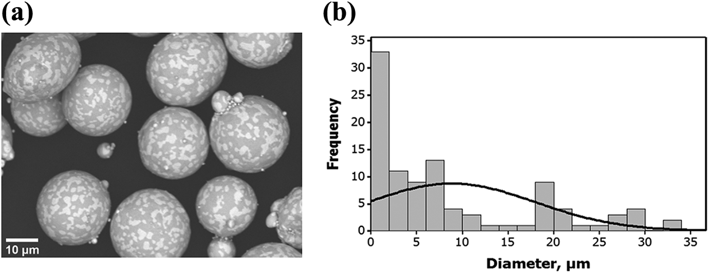
(a) SEM image of the SnBi powder used in this study and (b) measured size distribution.
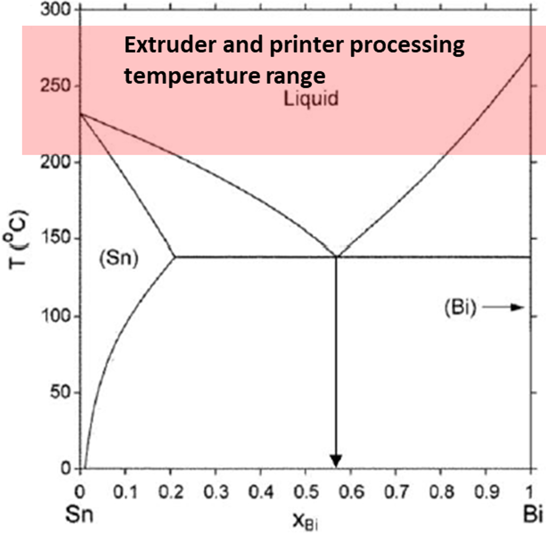
Phase diagram indicating the composition of the alloy and the material processing range for the polymers used in this study. Diagram from Kattner. 16
Three different polymer systems were studied: ABS grade MG94 in pellet form manufactured by SABIC (Pittsfield, MA, USA) under the Cyclolac™ product line, PLA 4043D biopolymer in pellet form manufactured by NatureWorks (Blair, NE, USA) under the Ingeo™ product line, and a polymer blend based on ABS grade MG94 that was compounded with a thermoplastic elastomer (Kraton FG1901-GT, Kraton, Houston, TX, USA) consisting of a triblock polymer based on SEBS-g-MA. The mechanical properties of this polymer blend have already been reported by Siqueiros et al. 14 For brevity, SEBS-g-MA will be referred simply as “SEBS” hereafter in this work. Different compositions of this polymer blend with varying weight percentages (25, 50, and 75%) of SEBS were produced and used as a baseline to be compared with the hybrid material.
Prior to extrusion, a functionalization process similar to that used in previous works by our group as found in Roberson et al., 4 Shemelya et al., 6,17 Carrete, 18 as well as others 19,20 was performed in order to achieve a better alloy particle dispersion within the polymer matrix. Two different silane-based functionalization agents were used in this study, one geared toward ABS and the ABS:SEBS blends (vinyltrimethoxysilane, Sigma-Aldrich, St. Louis, MO, USA) matrices and a second one for the PLA matrix ((3-glycidyloxypropyl) trimethoxy-silane, Sigma-Aldrich). The polymer pellets were dried in a compressed air dryer (Dri-Air CFAM Micro-Dryer, East Windsor, CT, USA). The ABS pellets were dried at 80°C for 2 h, the SEBS pellets were dried at 70°C for 4 h, and the PLA pellets were dried at 80°C for 4 h. The drying time and temperatures were determined based on the manufacturer-supplied material data sheets.
Because of the acceptable performance, simple design, ruggedness, and reliability of a single screw extruder, 9 a Filabot EX2 (Barre, VT, USA) was used to produce compatible FDM system filaments from the hybrid materials. The small-scale extruder facilitated the compounding of low quantity batches (80 g for each composite system). The metal powder and the polymer pellets were mixed manually within a beaker. The filament diameter size obtained for all the systems was 1.75 ± 0.05 mm.
When using blends composed of ABS and SEBS, the base resin was first compounded using the Filabot EX2 single screw extruder and the resulting filament was then pelletized through the use of a Dr. Collin pelletizer (Dr. Collin GmbH, Ebersberg, Germany). The pelletized filament was then manually mixed with the SnBi powder and fed to the Filabot EX2 extruder. Figure 3 shows the resulting filament for one of the ABS:SEBS—5% by weight (5 wt%) SnBi systems and printed parts for all three ABS:SEBS—5 wt% SnBi systems and one for the PLA—5 wt% SnBi system. Table 1 shows the compositions for the different polymer blend systems and the extrusion temperatures used for each system. In the case of ABS:SEBS blends and PLA loaded with SnBi particles, the extrusion parameters were altered slightly over the matrix materials in order to achieve a satisfactory filament diameter. The diameter was measured real-time by hand using a Mitutoyo (Aurora, IL, USA) digital caliper.
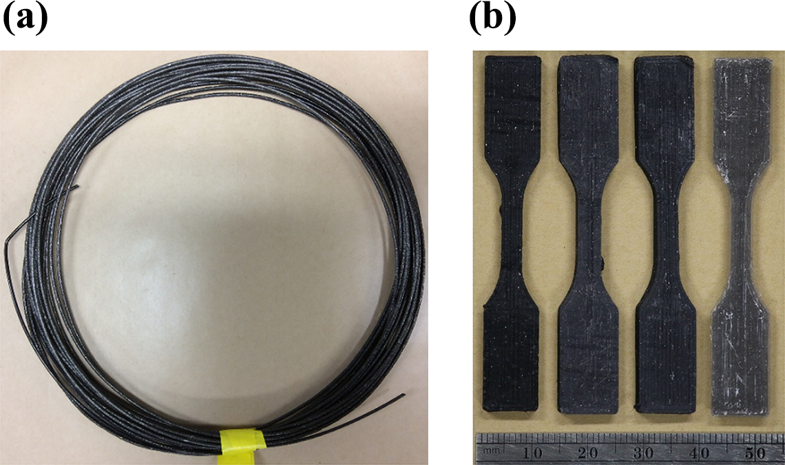
(a) Monofilament produced from the ABS:SEBS–5% SnBi system and (b) printed tensile specimens produced from the ABS:SEBS–5 wt% SnBi and PLA–5 wt% SnBi hybrids. From left to right, matrices composed of ABS:SEBS 75:25, ABS:SEBS 50:50, ABS SEBS 25:75, and PLA.
Extrusion temperatures.
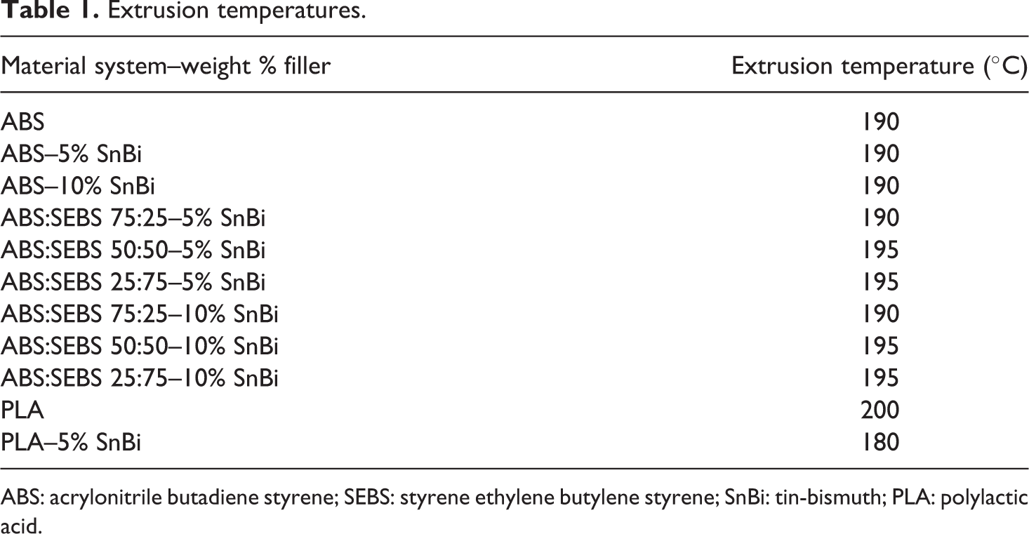
ABS: acrylonitrile butadiene styrene; SEBS: styrene ethylene butylene styrene; SnBi: tin-bismuth; PLA: polylactic acid.
Tensile test specimens were printed following the ASTM Standard D638-14 for the Type V dimension. The tensile test specimens were printed using a Lulzbot TAZ 5 (Aelph Objects Inc., Loveland, CO, USA) outfitted with a 0.8 mm nozzle tip. The samples were printed in the XYZ build orientation and an infill of 100% in a rectilinear pattern consisting of alternating layers of 0° and 90°. The printing parameters for each system are reported in Table 2. It should be noted that this printer was modified over the stock version by converting the print head to a 1.75 mm E3D V6 hot end (E3D-Online Limited, Chalgrove, Oxfordshire, UK). The print parameters for the ABS:SEBS system were originally developed by the work of Siqueiros et al. 14 We found that we did not have to alter the parameters for the loaded materials in order to achieve a satisfactory print.
Printing parameters.
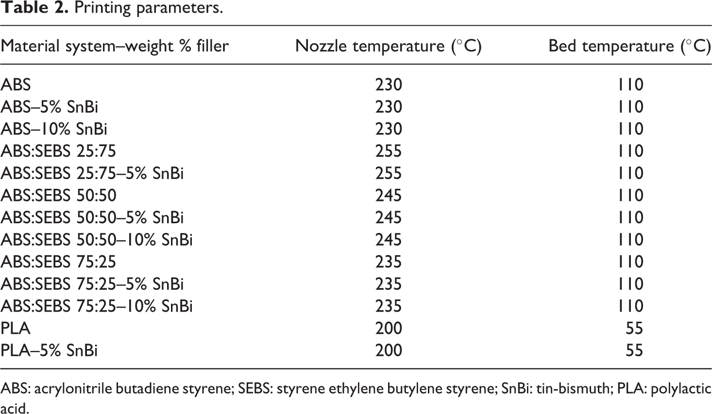
ABS: acrylonitrile butadiene styrene; SEBS: styrene ethylene butylene styrene; SnBi: tin-bismuth; PLA: polylactic acid.
Evaluation of mechanical properties was done using an Instron 5866 (Instron, Norwood, MA, USA) equipped with a 10 kN load cell. At least three specimens per material system were tested at a strain rate of 10 mm/min and a temperature of 23°C. In order to determine the instant strain at every moment, an Instron 2663-821 advanced video extensometer was used. This allowed the plotting of the entire stress–strain curve and the automatic calculation of the modulus and strain at break.
Fracture surface analysis was done using a Hitachi TM-1000 SEM (Hitachi High-Technologies Europe GmbH, Germany) operating with a 15 kV accelerating potential and equipped with a backscatter electron detector. The specimens were gold coated using a JEOL Smart Coater (JEOL, Peabody, MA, USA). More than one test specimen from each system was observed under the SEM in order to characterize the degree of in situ wire drawing of SnBi particles, common failure modes, and fracture surface morphology within each system.
Results
In carrying out the experiments for the materials tested in this study, in some cases, especially at higher loadings of SnBi, fabrication of test specimens was difficult resulting in sample pool sizes varying in number. In order to compare the mechanical testing results, Tukey–Kramer honest significant difference (HSD) was used using JMP (Version 11, SAS Institute, Inc., Cary, NC, USA). The reason Tukey–Kramer was used as a data analysis method to compare the mechanical testing results of the mechanical testing was because this method of comparing means of data sets is not affected by differences in sample pool size. A key question we sought to answer in this work was whether or not the silane functionalization process would be effective considering the processing temperatures were above the T m of the metal alloy composition as indicated by the liquidus line of the phase diagram shown in Figure 2. As such, paired experiments were carried out for each polymer matrix composition (ABS:SEBS blend, ABS, or PLA) between functionalized and nonfunctionalized SnBi powder.
ABS–SnBi hybrid
The mechanical test results for specimens printed from the composite of ABS loaded with SnBi are tabularized in Table 3 and graphically represented in Figure 4. The Tukey–Kramer HSD test of each sample pool is represented by the circles at the right of each graph, where a decrease in overlap of a given pair of circles represents an increase in statistical difference between data pools. Functionalizing the SnBi powder prior to compounding had a statistically significant effect on the ultimate tensile strength of the printed specimens for the 5 wt% loading as compared to ABS baseline specimens (37.82 ± 1.76 MPa as compared to 33.17 ± 1.12 MPa). In assessing the efficacy of the silane functionalization process, the nonfunctionalized sample pool of the 5 wt% loading of SnBi yielded an ultimate tensile strength (UTS) value of 28.22 ± 2.12 MPa, which indicated the functionalization process improved the tensile properties most likely by increasing the bond strength between the metal particles and the polymer matrix. When the weight percent of SnBi powder was increased to 10%, the improvement to UTS was not realized as compared to ABS baseline specimens as the UTS values were decreased. Additionally, increasing the loading to 10 wt% SnBi diminished the impact of the functionalization process as the difference between the functionalized and nonfunctionalized sample pools was not statistically significantly different. Representative stress–strain curves for the ABS–SnBi system are seen in Figure 5.
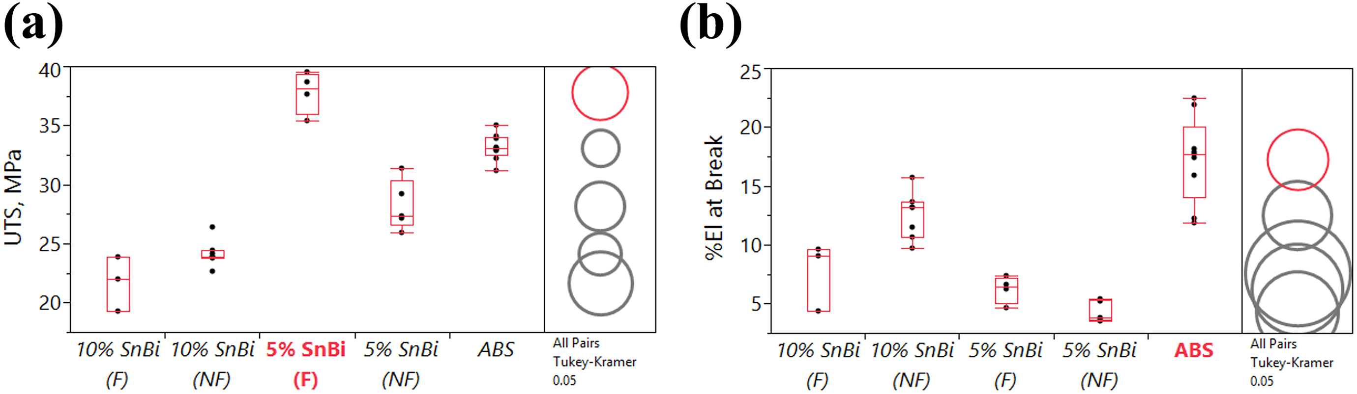
Mechanical test results for the ABS–SnBi system. (a) UTS and (b) tensile strain (% elongation) at break values.
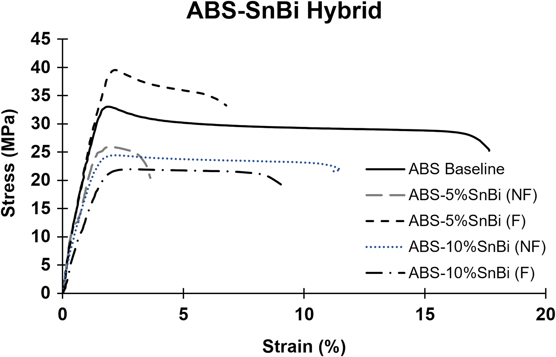
Representative stress–strain curves for the ABS–SnBi hybrid system.
Tensile test results for the ABS–SnBi system.
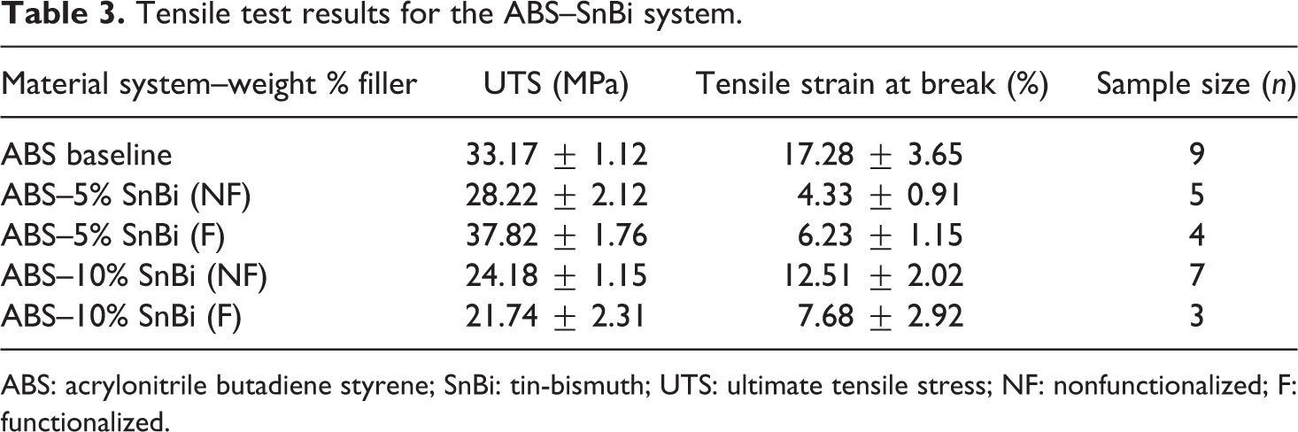
ABS: acrylonitrile butadiene styrene; SnBi: tin-bismuth; UTS: ultimate tensile stress; NF: nonfunctionalized; F: functionalized.
ABS:SEBS–SnBi hybrid systems
As was the case when ABS was used as a base resin, two loading conditions were evaluated when blends composed of ABS:SEBS were employed as a thermoplastic matrix. For clarification, the blends are denoted as ABS:SEBS XX:XX, where XX:XX refers to the weight ratio of ABS:SEBS. For the ABS:SEBS blends, the effect of functionalization was also evaluated. It should be noted that for the ABS:SEBS 25:75 matrix material, it was not possible to successfully fabricate a viable filament loaded with 10 wt% SnBi.
Table 4 lists the results of the tensile testing for the whole ABS:SEBS system, that is, 75:25, 50:50, and 25:75. All values represent the average obtained from the specimens pulled out for each composition. Figure 6 is a graphical representation of these same values using Tukey–Kramer HSD as a comparison metric. Similar to when ABS was the polymer matrix, loading of functionalized 5 wt% SnBi provided a statistically significant increase in the UTS values when ABS:SEBS 75:25 and 25:75 was used as a polymer matrix. However, when ABS:SEBS 50:50 was used as a matrix material, none of the loadings of functionalized conditions yielded a statically significant difference from the baseline UTS values. A higher loading of the SnBi alloy was introduced in the ABS:SEBS 75:25 and 50:50 systems for both functionalized and nonfunctionalized cases. It has been shown that the particle loading percentage as well as the interfacial adhesion can affect the mechanical properties. 19,20 With this higher loading (10 wt%) of metal powder, the functionalization process had less impact and the UTS was almost the same for both cases (functionalized and nonfunctionalized) in the 75:25 system. However, there was a decrease in the UTS with a 10% SnBi loading when compared to the 5 wt% loading.
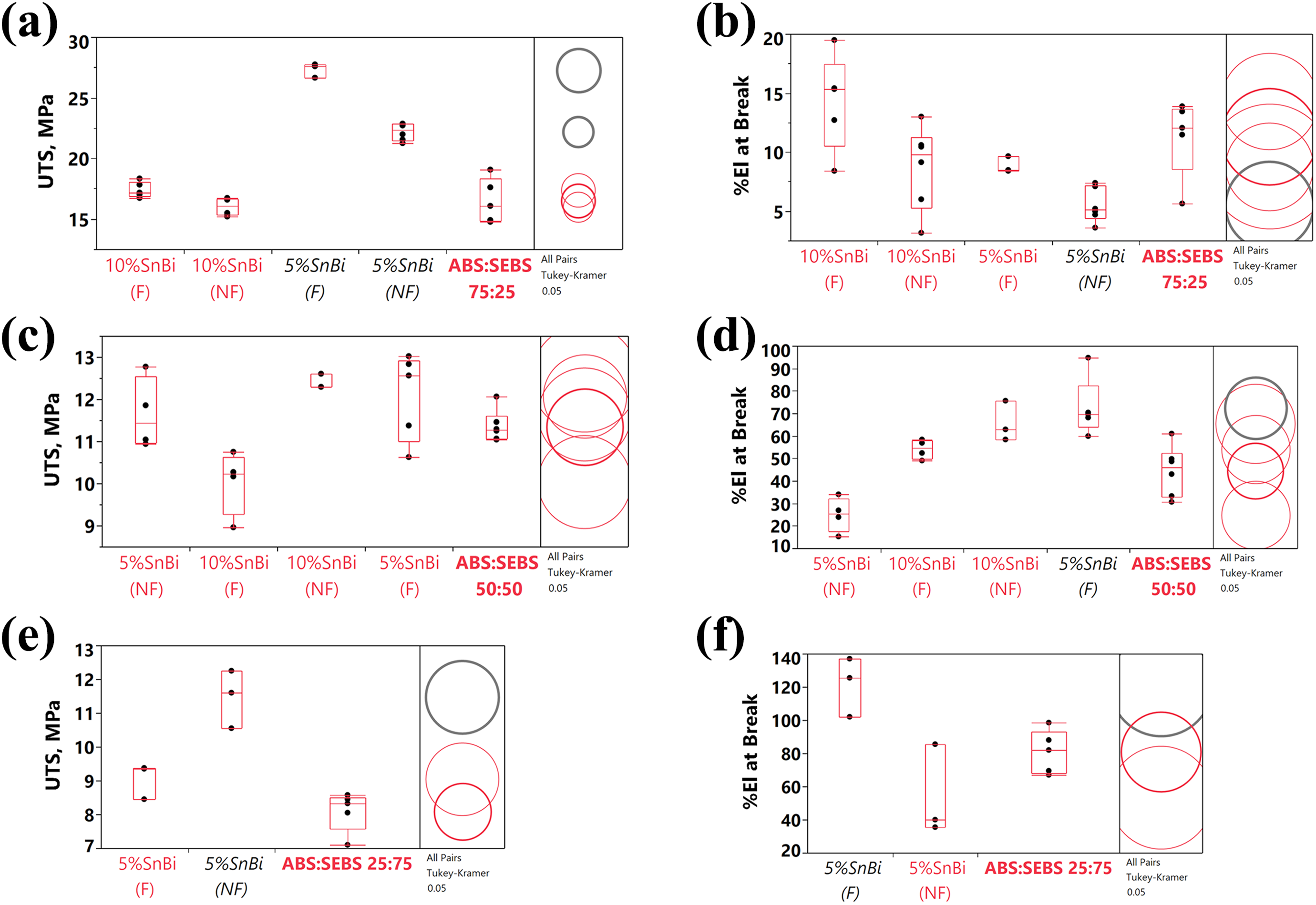
Mechanical test results for the ABS:SEBS–SnBi system. (a) UTS and (b) % elongation for the 75:25–SnBi system; (c) UTS and (d) % elongation for the 50:50–SnBi system; (e) UTS and (f) % elongation for the 25:75–SnBi system.
Tensile test results for the ABS:SEBS–SnBi system.
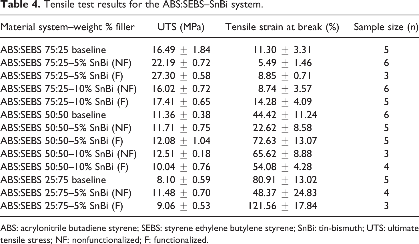
ABS: acrylonitrile butadiene styrene; SEBS: styrene ethylene butylene styrene; SnBi: tin-bismuth; UTS: ultimate tensile stress; NF: nonfunctionalized; F: functionalized.
In terms of percent elongation at break, the 75:25–10% SnBi system exhibited an increase when compared to the 5% SnBi system. The value of tensile strain at break for the functionalized 75:25–10% SnBi system was even larger than the value for the corresponding baseline as seen in Figure 6(a).
The functionalized 50:50–10% SnBi system exhibited a decrease in percent elongation at break as compared to the functionalized 50:50–5% SnBi system. However, this value (54.08 ± 4.28%) was still larger than the 50:50 baseline, however not by a statistically significant amount. In terms of percent elongation, the loading of 5 wt% functionalized SnBi provided an increase as compared to the baseline specimens.
Finally, for the ABS:SEBS 25:75 system, the larger fraction of the polymer matrix was composed of thermoplastic rubber and initial studies characterizing this blend noted unexpected rheological behavior 14 and in the work presented here, experiments involving this matrix material exhibited the greatest UTS values when the matrix was loaded with nonfunctionalized SnBi. This result indicates that the maleic anhydride graft in the SEBS becomes a dominating factor when the weight ratio is greater than that of the ABS and that the functionalization process imparts a malefic when higher concentrations of SEBS-g-MA are used. The Tukey–Kramer HSD analysis (Figure 6(e)) indicates the difference was statistically significantly different. In terms of percent elongation at break (Figure 6(f)), the system that exhibited the greatest values was the composite loaded with 5 wt% functionalized SnBi. As mentioned above, it was not possible to fabricate specimens loaded with 10 wt% SnBi when using ABS:SEBS 25:75 as a matrix material.
To summarize the results of the ABS:SEBS loaded material systems, it can be seen from Figure 6(a), (c), and (e) that there was an increase in the UTS when the loading was 5 wt% SnBi for the various ABS:SEBS blends evaluated in this study. In the case of the 50:50 system, there was an incremental increase in the UTS with a 10% SnBi loading (nonfunctionalized). A larger gain in UTS was observed in the 25 wt% SEBS, as the values increased from 16.49 ± 1.84 MPa to 22.19 ± 0.72 MPa. The increase was more substantial (27.30 ± 0.58 MPa) when the filler material was functionalized (see Table 4). The functionalization process had a positive impact on the UTS for the 25 wt% and 50 wt% SEBS (the 75:25 and 50:50 ABS:SEBS blends) and proved to be beneficial to both SnBi loadings (5% and 10%) in the case of the ABS:SEBS 75:25 blend. In the case of the 50:50 blend, the functionalization process did not have a profound effect on the UTS values of specimens loaded with 5 wt% SnBi. On the other hand, functionalizing the filler material had a detrimental effect on both the UTS and elongation at break in the case of the 50:50 blend loaded with 10 wt% SnBi. Figures 7 to 9 depict the representative stress–strain curves obtained for the ABS:SEBS–SnBi system.
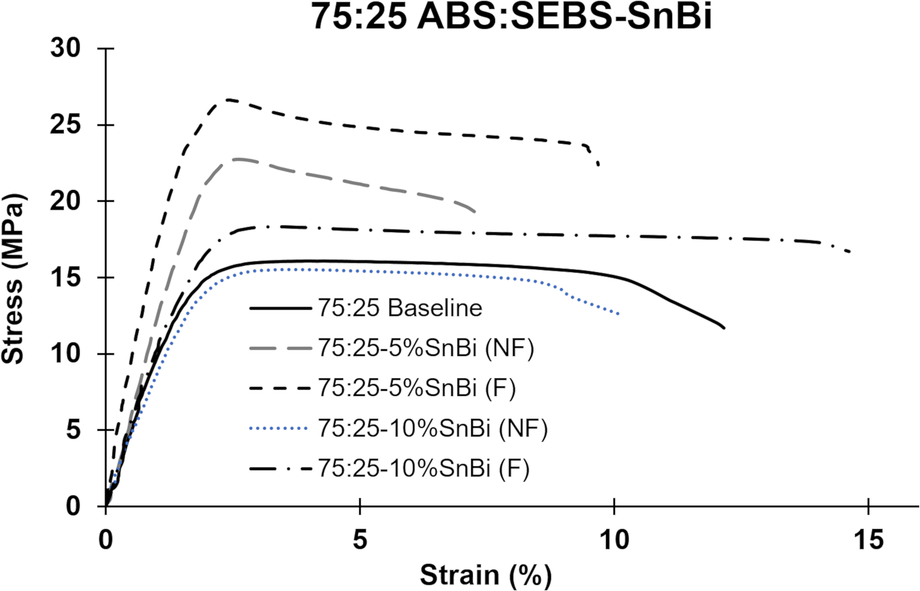
Representative stress–strain curves for the ABS:SEBS–SnBi hybrid systems for the 75:25 blend as a matrix.
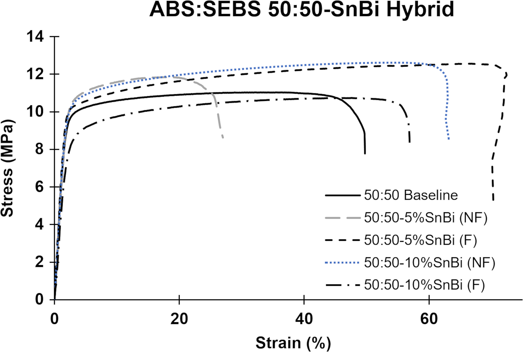
Representative stress–strain curves for the ABS:SEBS 50:50–SnBi hybrid system.
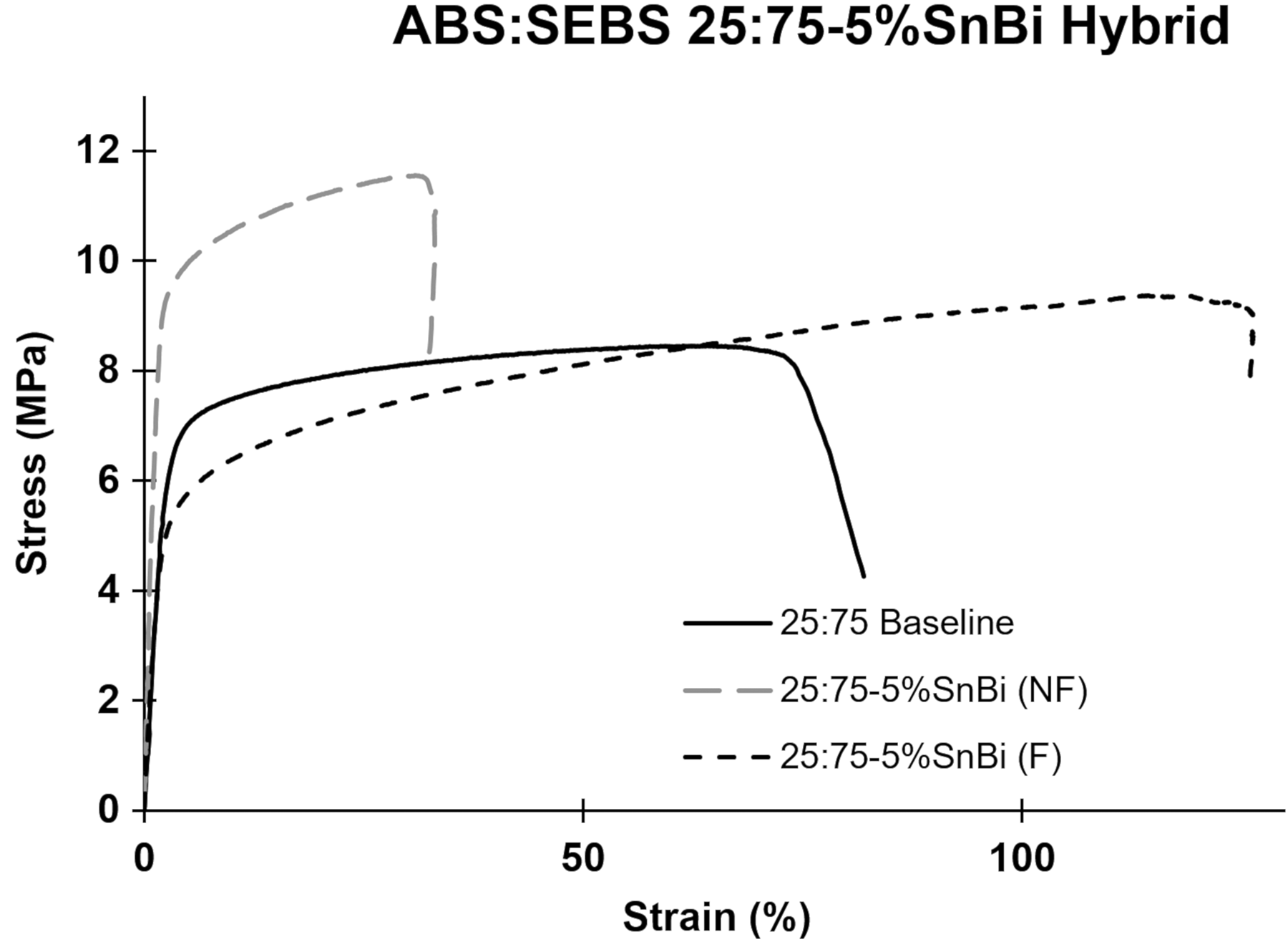
Representative stress–strain curves for the ABS:SEBS 25:75–5% SnBi hybrid system.
PLA–SnBi hybrid
For the PLA–SnBi hybrid, both functionalized and nonfunctionalized systems were produced and a monofilament loaded with 5 wt% SnBi was obtained. As was the case with the ABS:SEBS 25:75 blend described above, it was not possible to produce a printable monofilament composed of PLA loaded with 10 wt% SnBi. The results of the mechanical testing for the PLA–5% SnBi system are shown in Table 5. Figure 10(a) shows the obtained UTS values where it can be seen that not functionalizing the SnBi prior to compounding had a detrimental effect on the UTS values (43.71 ± 4.46 MPa as compared to 53.94 ± 0.95 MPa for baseline specimens). When the SnBi material was functionalized, there was a slight, but not significant increase in UTS as compared to the PLA baseline, but the percent elongation (Figure 10(b)) was decreased from 6.95 ± 0.47% to 3.56 ± 0.86% meaning the resulting hybrid material was stiffer as compared to PLA alone. Representative stress–strain curves for PLA and the composites composed of PLA and SnBi are displayed in Figure 11.
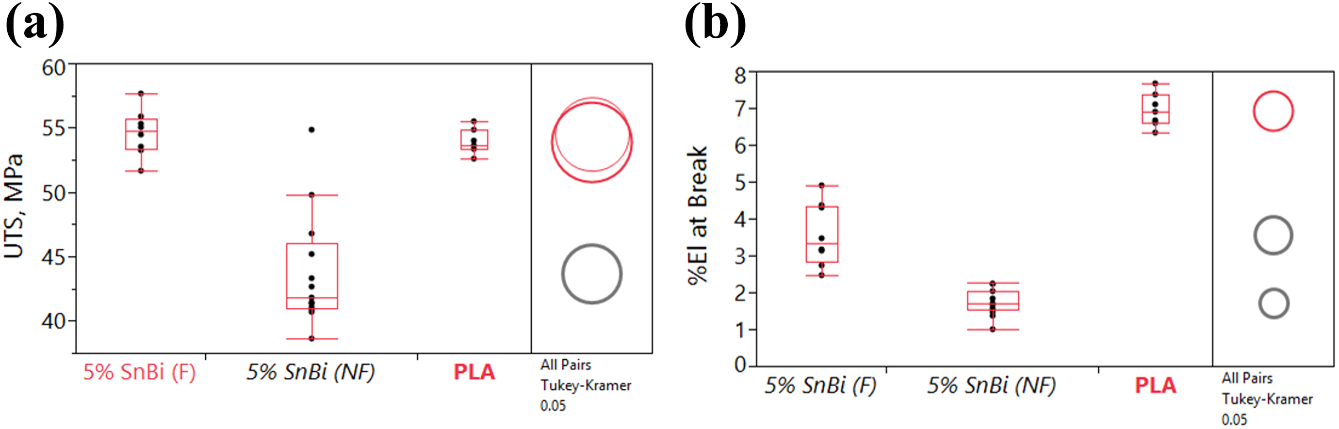
Mechanical test results for the PLA–SnBi system. (a) UTS and (b) tensile strain (% elongation) at break values.
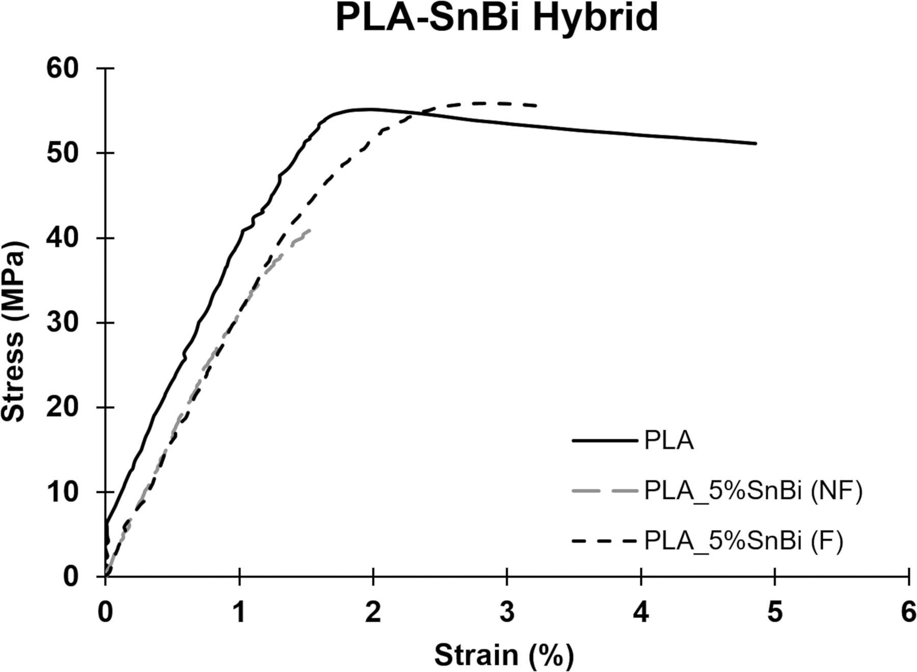
Representative stress–strain curves for the PLA–SnBi hybrid system.
Tensile test results for the PLA–SnBi system.
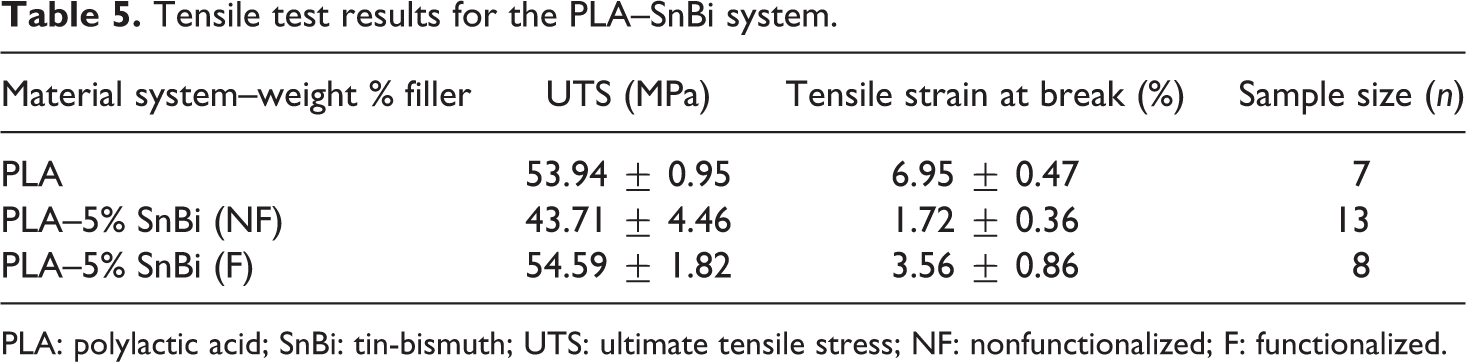
PLA: polylactic acid; SnBi: tin-bismuth; UTS: ultimate tensile stress; NF: nonfunctionalized; F: functionalized.
Scanning electron microanalysis
Filament
Electron microanalysis of ABS filament loaded with 5 wt% SnBi powder (Figure 12) revealed that drawing of the particles did not occur on a grand scale during the extrusion process. Analysis of the axial cross section revealed that, to a large degree, the morphology of the SnBi particles remained unchanged particularly at the center of the filament seen at a higher magnification in Figure 12(b). When examining the surface of the filament, it was revealed that some drawing of the SnBi had occurred (Figure 12(c)). Drawing on the surface may be due to higher forces acting on the outer surface of the filament as compared to the center of the filament. The degree of drawing varied from system to system and the ABS:SEBS systems appeared to exhibit a higher degree of drawing on the surface of the filament as indicated by the white arrows in Figure 12(d).
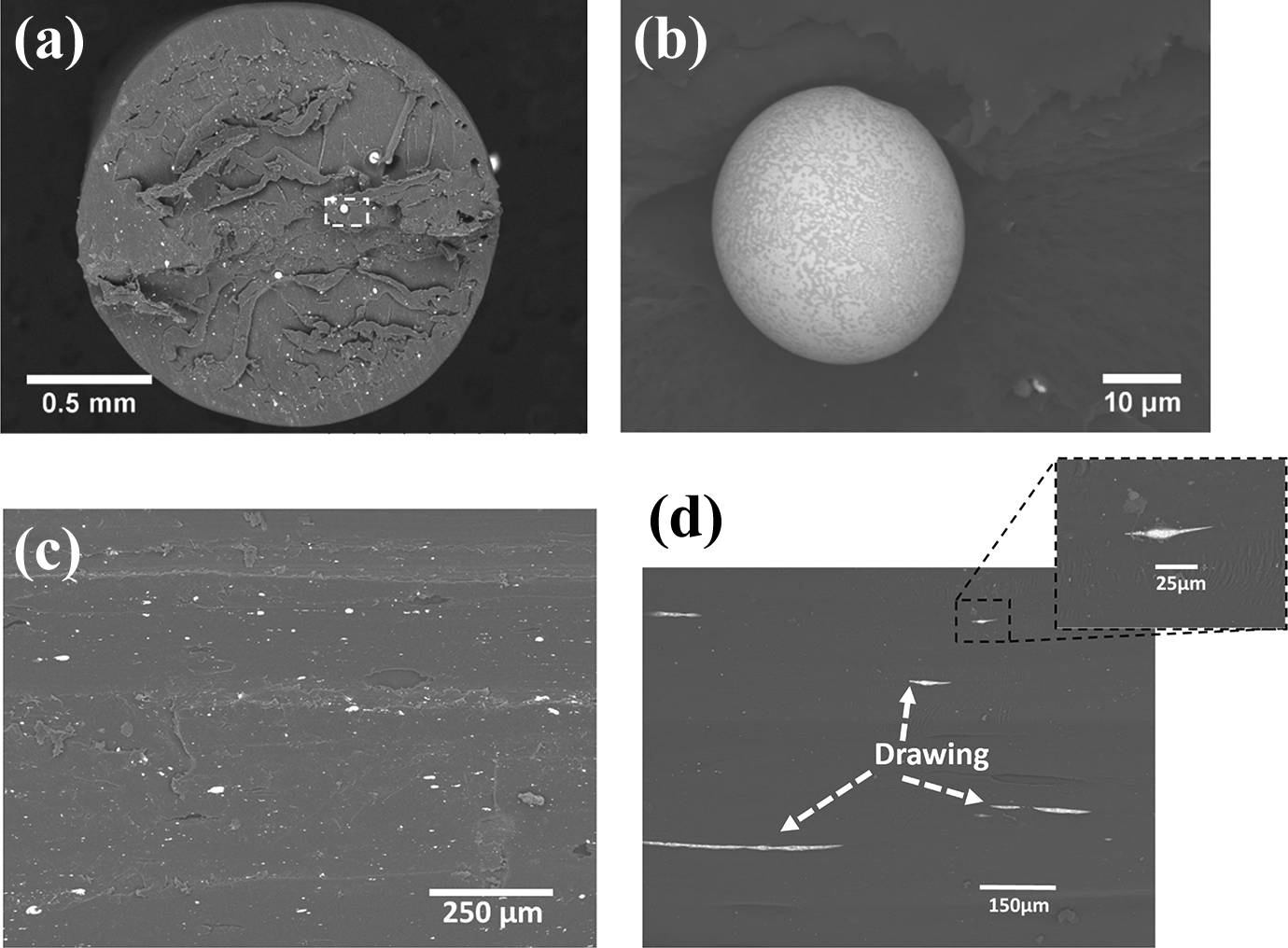
SEM images of the transverse cross section of a filament from the (a) ABS–5% SnBi (nonfunctionalized) system, (b) higher magnification of the square in (a), (c) external surface of the ABS filament, and (d) external surface of the ABS:SEBS 25:75 blend loaded with 10 wt% SnBi.
Fracture surface analysis of tensile specimens
ABS–SnBi system
As noted when examining the tensile test results, the silane functionalization process had a positive impact on the UTS for the ABS–5% system. As can be seen in Table 3, the ABS baseline specimens had UTS values of 33.17 ± 1.12 MPa, whereas the nonfunctionalized specimens had UTS values of 28.22 ± 2.12 MPa both compared to 37.82 ± 1.76 MPa for specimens loaded with functionalized SnBi powder. Scanning electron microanalysis correlated well with the tensile results as it was observed that a better dispersion of SnBi particles within the ABS matrix was achieved through the functionalization process and some drawing of particles was observed throughout the ABS matrix (see Figure 13(a)). On the other hand, agglomerates of the alloy particles were observed when no functionalization was performed, (see Figure 13(c)) proving detrimental for the mechanical properties. Also observable in Figure 13(c) is the presence of voids due to the additive manufacturing process. The voids were also observed in the case of the specimens loaded with nonfunctionalized SnBi particles and were determined to not be the cause of the difference in mechanical properties between the two experiments. Were we making a comparison between the FDM-type manufacturing process and injection molding we would expect injection molded parts to exhibit superior mechanical properties as has been observed in the literature. 21 The beneficial effect of functionalizing filler materials on the size of agglomerates and resultant mechanical properties has been observed in previous works by our group. 4
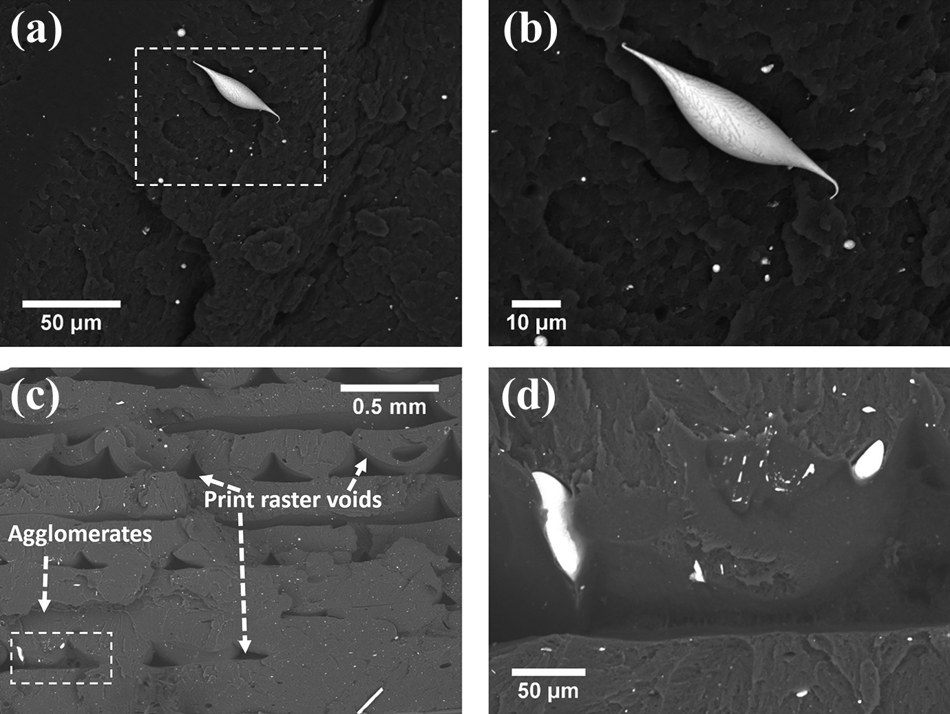
SEM micrographs of the fracture surface of (a) an ABS–5% SnBi (functionalized) specimen; (b) higher magnification (square in (a)) of drawing SnBi particles dispersed on ABS matrix; (c) fracture surface of an ABS–% SnBi (nonfunctionalized) specimen; (d) square in (c).
ABS:SEBS–SnBi system
Similar to observations made in the ABS–SnBi system, the functionalization process had a positive impact on the UTS for the ABS:SEBS–5% system. SEM microanalysis revealed that SnBi particles were better dispersed when the particles were functionalized and some exhibited drawing (Figure 14(a) and (b)). In the case of the 5% SnBi nonfunctionalized systems, agglomerates of SnBi particles were prevalent throughout the ABS:SEBS matrix as can be seen in Figure 14(c) and (d). As was the case for the ABS system, when the weight percent of the metal alloy was increased to 10%, the functionalizing process did not have a positive effect on the mechanical properties. Agglomerates were present in the functionalized systems as shown in Figure 14(e) and (f), meaning that the silane functionalization did not have the same positive effects as observed with a lower loading of 5 wt%. Although Figure 14 only shows the SEM micrographs of the 75:25–5% SnBi system, the same behavior was also observed in the other ABS:SEBS systems, that is, agglomeration of SnBi particles in nonfunctionalized specimens for the 5 wt% SnBi systems and agglomeration in both functionalized and nonfunctionalized for the 10 wt% SnBi systems.
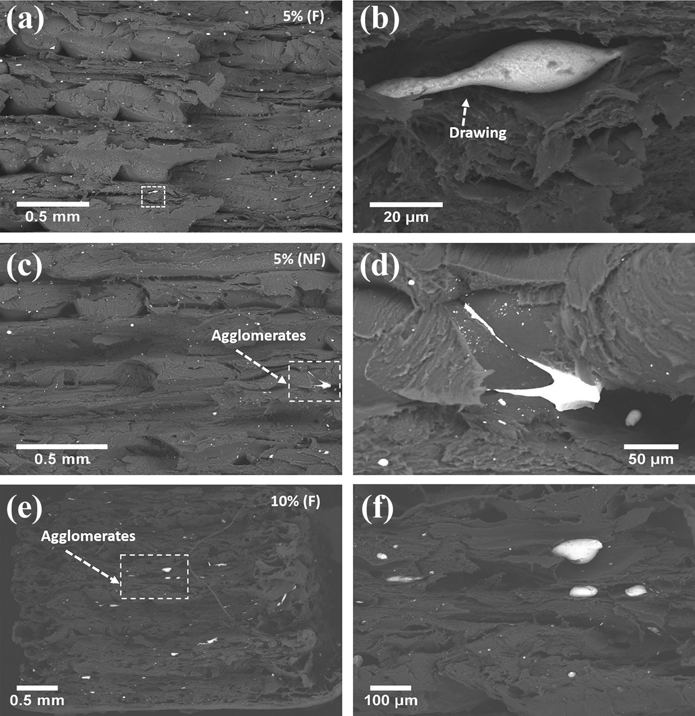
SEM micrographs of the fracture surface of tensile specimens from the (a) 75:25–5% SnBi (functionalized) system; (b) square in (a); (c) 75:25–5% SnBi (nonfunctionalized) system; (d) square in (c); (e) 75:25–10% SnBi (functionalized) system; (f) square in (e).
PLA–SnBi system
Microanalysis of the PLA loaded with SnBi revealed that in both the cases of functionalized and nonfunctionalized experiment sets, the SnBi particles were drawn into wires. The drawing was observed to be in the direction of the print raster as indicated in Figure 15(f). The morphology of the drawn SnBi material possessed a morphology different from that observed in the ABS systems and in some cases manifested in well-formed rod-like structures (indicated by white arrows in Figure 15(c)). The drastic difference in size of the elongated SnBi material indicates that agglomeration did occur, but did not inhibit the change in morphology of the metal alloy within the polymer matrix. Comparison of the fracture surfaces from the functionalized and nonfunctionalized fracture surfaces did not reveal any drastic differences between the behavior of the SnBi within the polymer matrix, which correlates well with the tensile testing data.
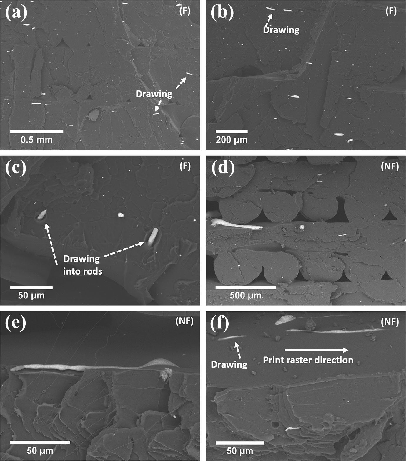
SEM micrographs of the fracture surface of tensile specimens from the PLA–5% SnBi system, F and NF. (a) Inset is a higher magnification of the small white square; (b) SnBi particles dispersed on PLA matrix; (c) wire-like SnBi particles indicated by arrows; (d) arrow shows drawing of SnBi particles on the PLA matrix; (e) and (f) drawing of agglomerated SnBi particles.
The reason for the differences in morphology between the drawn SnBi particles within the PLA matrix as compared to the other matrix materials used in this study may be due to viscosity differences between the different polymers. Previous work performed by Siqueiros and Roberson 1 involved melt flow index (MFI) measurements of PLA and the ABS:SEBS system and noted that the MFI values of PLA were lower than those of the ABS:SEBS blend utilized in that study. Though not a direct measurement of viscosity, the lower MFI value indicated a higher viscosity. The agglomeration most likely occurred during the compounding process, meaning that the wire drawing occurred during the printing process as was also the case with prior work involving the previously mentioned wire drawing of tin phosphate glass in PLA. 1 In the case of PLA, the key driver for successfully drawing the material into wires was viscosity and not the functionalization process.
Conclusions
The work presented in this study demonstrated the development of three different hybrid (polymer–metal) composite materials intended for 3-D printing platforms based on FDM™ technology. Characterization of the mechanical properties of the ABS:SEBS–5% and 10% SnBi and the PLA–5% SnBi hybrids demonstrated the compatibility of these novel hybrid material systems with conventional FDM-type 3-D printing platforms. An increase in the ultimate tensile strength was observed in these blends when compared to baseline ABS, ABS:SEBS, and PLA mechanical property values, though not always statistically significant. Observation of representative fracture surfaces the hybrid blends indicated that drawing of the SnBi particles had occured as the morphology of the particles had changed from spherical to elongated. Feedstock material (filament) was also observed under the SEM confirming this drawing of the spherical SnBi particles into wires.
The efficacy of a silane functionalization process was demonstrated in the case of ABS loaded with 5 wt% SnBi. This was a significant finding as the metal alloy was processed above the T m. The silane functionalization process had a positive impact on the ABS:SEBS systems with the exception of the 75 wt% SEBS blend indicating that the maleic anhydride graft component of the SEBS may have a negative interaction with the functionalization process. The functionalization process also had an effect on the PLA system, however, the process only mitigated a detrimental effect as the functionalized specimens yielded similar UTS values similar to the PLA baseline specimens. In terms of successfully drawing the SnBi material into wires, the functionalization process was less of a factor in the case of the PLA system as compared to the viscosity of the matrix material.
The work presented here demonstrates the development and characterization of hybrid metal/polymer systems for FDM-type 3-D printing. These hybrid systems differ from polymer matrix composites in that the morphology of the filler material changes during the filament fabrication and subsequent printing processes. This premise is different than the typical strategy for creating polymer matrix composites as the general reason to make a composite is to alter the properties of the matrix material rather than the morphological characteristics of the filler material. The materials processing concept presented here will serve to expand the premise of materials development for 3-D printing platforms.
Footnotes
Authors’ note
The work presented here was performed in the Polymer Extrusion Lab in the Department of Metallurgical, Materials and Biomedical Engineering at the University of Texas at El Paso. The authors thank Philip Morton for his contribution to this work.
Funding
The author(s) disclosed receipt of the following financial support for the research, authorship, and/or publication of this article: Funding for this work was provided by the AFOSR through the Young Investigator Program (YIP) under grant number FA9550-14-1-0260 and the Defense University Instrumentation Program (DURIP) under grant number FA9550-15-1-0312.