
Abstract
This study shows the benefit of a new composite material in terms of energy absorption for the automotive application. The ability of a tubular structure made of a glass fibers–reinforced thermoplastic matrix to absorb energy has been studied in this work. The pseudoplastic behavior of ±45° orientation used to build the different specimens allows a great level of damage in the composite. In particular, the influence of the section of the absorber on the global response to the shock and so on the amount of absorbed energy has been checked. A continuum mechanics model on Abaqus is used to compare different kinds of sections too complexed to be manufactured by standard process at low cost. The use of an external conical trigger is studied and presents a more stable energy absorption, constant all along the crushing.
Introduction
In the automotive application, the absorption of the energy released during a car accident is realized by the plastic deformation of metallic absorbing systems. 1 However, the tightening of laws on greenhouse gas emissions forces the automotive industry to optimize the design of all car systems. In particular, studies are led to reduce the mass of vehicles, improving the power/weight ratio of vehicles. This will directly limit the fuel consumption and the production of harmful gases. The use of optimized materials such as composites is so a priority issue including for complexed structures like absorbing systems. A new kind of materials still little used in automotive sector, laminated composites, owns mechanical properties similar to metals ones. However, they have the advantage of offering better performances in terms of energy absorption and a lower density, while being recyclable, than those of metallic materials, currently used for shock absorbing systems. 2 Moreover, the shock absorption scenario has to be constant all along the crash to avoid injuries on passengers because of too high levels of decelerations.
For composites, the energy absorption is achieved by damages and fractures, not through plastic deformation. 3 To maximize the amount of absorbed energy, progressive failure modes have to be preferred to catastrophic failure modes. 4 Hull 5 introduces these progressive modes into three kinds: fragmentation crushing (fracture of the composite in numerous debris), splaying crushing (a flare is observed due to interlaminar delamination), or brittle fracturing modes (combination of the two previous modes). The progressive mode followed by the composite during crash is indeed due to the damage mechanisms occurring inside the material during the crushing. At the scale of a ply, the kinetic energy released by the shock is consumed by the advent of these numerous mechanisms of damage: fiber rupture, matrix crack, and delamination. 6 These ruptures coupled with the friction induced between the material and the support allow the absorption of a more or less amount of energy. 7 The understanding of the failure mechanisms enables the optimization of the geometry and type of composite used to maximize the amount of absorbed energy. Actually, a large number of parameters related to the structure has a great influence on the local mechanisms 4 : geometry that is to say, for a tubular-based geometry, the kind of section used (square, circular, pyramid, etc.), 8 type of materials, 9 orientation of the plies, and so on. It is essential to study and to correctly determine these parameters to optimize the absorption.
In this article, a tubular shock absorber made by a specific laminated composite has been fixed: This study thus focuses on the effect of different kinds of tube sections and on the use of an external conical trigger on the global crash response of our material and finally on the amount of absorbed energy calculated, thanks to the specific energy absorption (SEA). Indeed, SEA quantifies the amount of energy used to crush a unit mass during a stable crash that is to say after the first loading of the composite resulting in an unstable phase (initial peak), calculated using the following

where Fmean plateau (N) = mean value of force measured during the stable plateau step (so after the initial peak corresponding to the contact between specimen and impactor), dmean plateau (m) = crush distance measured during the stable phase (plateau), ρ (g m−3) = specimen density, S (m2) = specimen section, and m (g) = specimen mass.
As Jacob 4 explains it, the stable step (plateau phase) can be difficult to determine for composite specimen, and the SEA then corresponds to the ratio between the total area under the load–displacement curve and the mass of material (method used in this study).
Since the 1990s, a large number of scientific studies have been carried out in order to exploit the ability of composites to absorb energy. Nevertheless, these studies concentrate on thermosetting matrix composites. 7,10 For industrialization purposes and due to the automotive constraints, the use of thermoplastic matrix is preferred (Omnium, 2015). 11 Some studies, moreover, demonstrate a greater energy absorption capacity for thermoplastic matrix than for thermosetting resin in composites, such as Polyetheretherketone (PEEK) matrix. 12
An example of these studies is the work of Schrank et al. 13 The authors investigated on a carbon fiber–reinforced plastic for automotive type shock absorbers and especially on numerical model to predict its behavior. The specific geometry used was a complex cone structure close to an automotive structural rail. Another study of composites used for crash absorption was developed by NASA Langley Research Center: A conical-shaped absorber made of hybrid carbon Kevlar fabric composite was designed for a ch46e helicopter to absorb energy from a drop. 14
Precisely, this study focuses on a laminated composite made of glass fibers and acrylic-based resin because of the interesting characteristics of its two constituents: high mechanical performance, density, processability, cost, and so on. This composite of specific acrylic resin can be processed by standard methods used on thermoplastic composite and is so interesting for a future industrialization in terms of cost and production rate.
Materials and methods
Geometrical characteristics of tubular structures
The ability of tubular structures made of a glass fibers–reinforced thermoplastic matrix to absorb energy is studied in this work. Quasi-static and dynamic compressive tests have been ruled on square and circular section composite tubes (Figure 1) manufactured by a resin transfer molding (RTM) process with a flexible membrane and aluminum absorbers (for references).
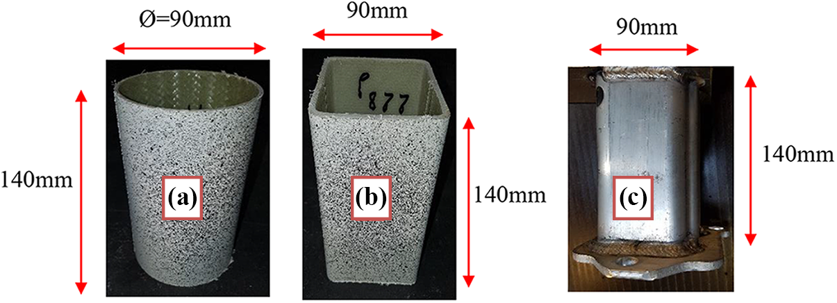
Specimen geometries of (a) circular, (b) square composite absorbers, and (c) aluminum reference absorber.
Glass fibers–reinforced thermoplastic matrix
Material properties
The composite material used for these structures is a [+45°/−45°]9 laminated composite made of non-crimp fabric (NCF) plies of glass fibers and an acrylic-based thermoplastic resin. Precisely, one ply of NCF reinforcement is composed by two unidirectional plies oriented as [+45°/−45°] linked by some weft yarns.
The different values of the mechanical properties of this glass fibers–reinforced acrylic matrix are given in Tables 1 and 2.
Quasi-static tensile and compressive elastic and fracture properties of NCF laminated composite.
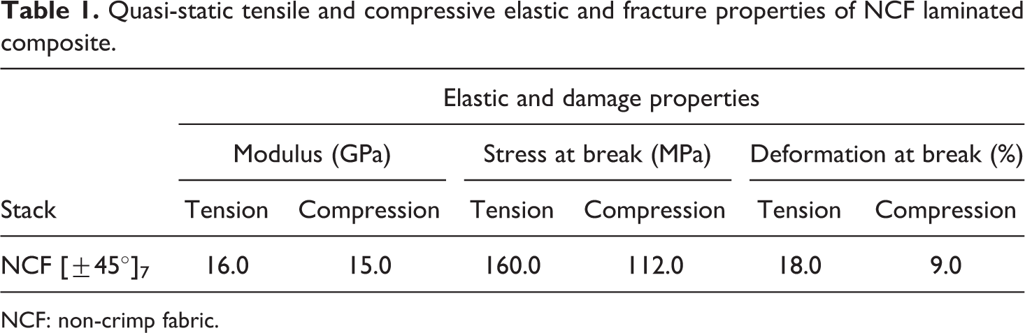
NCF: non-crimp fabric.
Quasi-static shear pseudoplastic properties of NCF laminated composite.
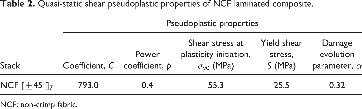
NCF: non-crimp fabric.
These mechanical parameters have been calculated from standard experimentations to characterize the composite and build the numerical model.
Material characterization tests
Tensile and compressive tests are almost always ruled to identify the main properties of the composite. 14 Indeed, compressive tests are important to check the possible difference of behavior in tension and compression of the composite material, even if having a pure compression test is quite complexed because of micro buckling. 15
First, tensile and compressive tests have been led to characterize the mechanical behavior of the glass/acrylic-based resin composite on five samples for each test. The NCF ±45° reinforcement is preferred because of its pseudoplastic behavior really interesting for the absorption of shock thanks to the optimized resistance-deformation couple. 16 Quasi-static (deformation rate of 10−3 s−1 ) tensile tests have been carried out on a ZWICK Z250 machine (Zwick/Roell international company, Austria) with a mechanical extensometer on 250 × 25 × 3.5 mm3 specimens with tabs (Figure 2), according to the standard NF EN ISO 527-4.
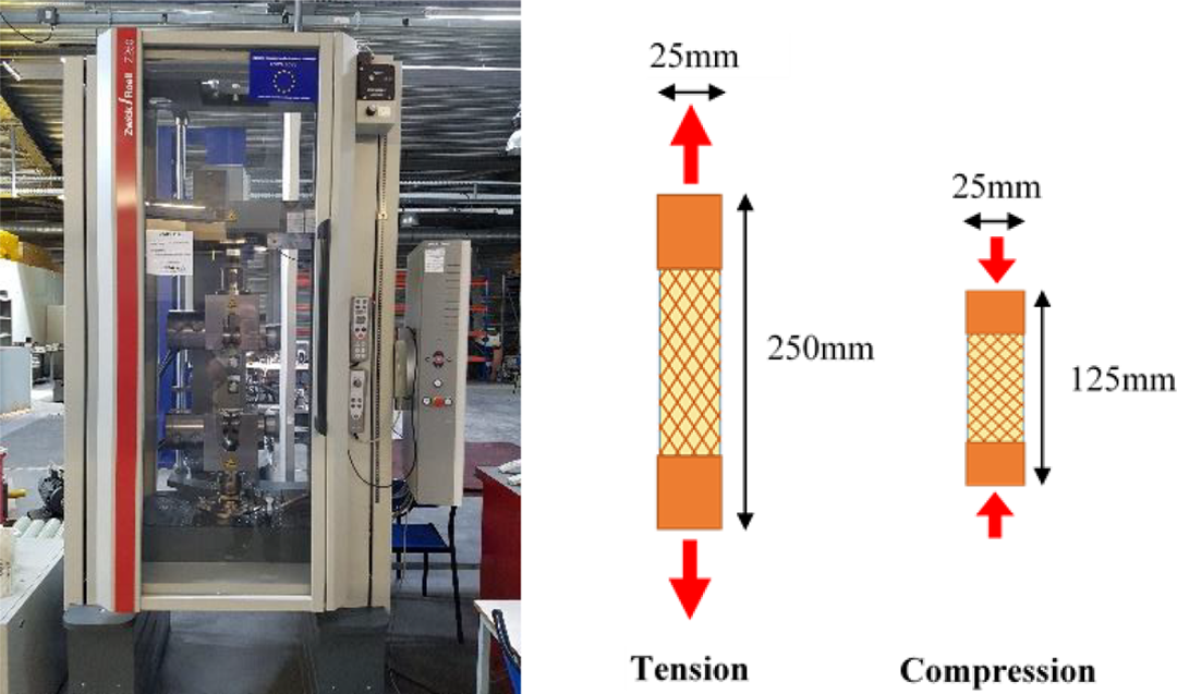
ZWICK Z250 quasi-static testing machine with specimen geometries.
Quasi-static compressive tests have also been made on NCF specimens (dimensions: 125 × 25 × 3.5 mm3) with tabs (Figure 2) according to the standard NF EN ISO 14126. For these tests, unidirectional strain gauges have been used to measure precisely the elastic deformation of the samples.
The tensile and compressive tests bring to light the interesting behavior of the NCF glass reinforcement. In general, under loading, [0°] n or [90°] n glass composites present, after an elastic linear phase, a sudden brittle break. On the contrary, ±45° NCF samples illustrate a higher deformation with this pseudoplastic step (Figure 3): The fibers begin to move and then the delamination between fibers and the matrix occurs; after that, ruptures in the matrix and fractures of the deformed fibers appeared.
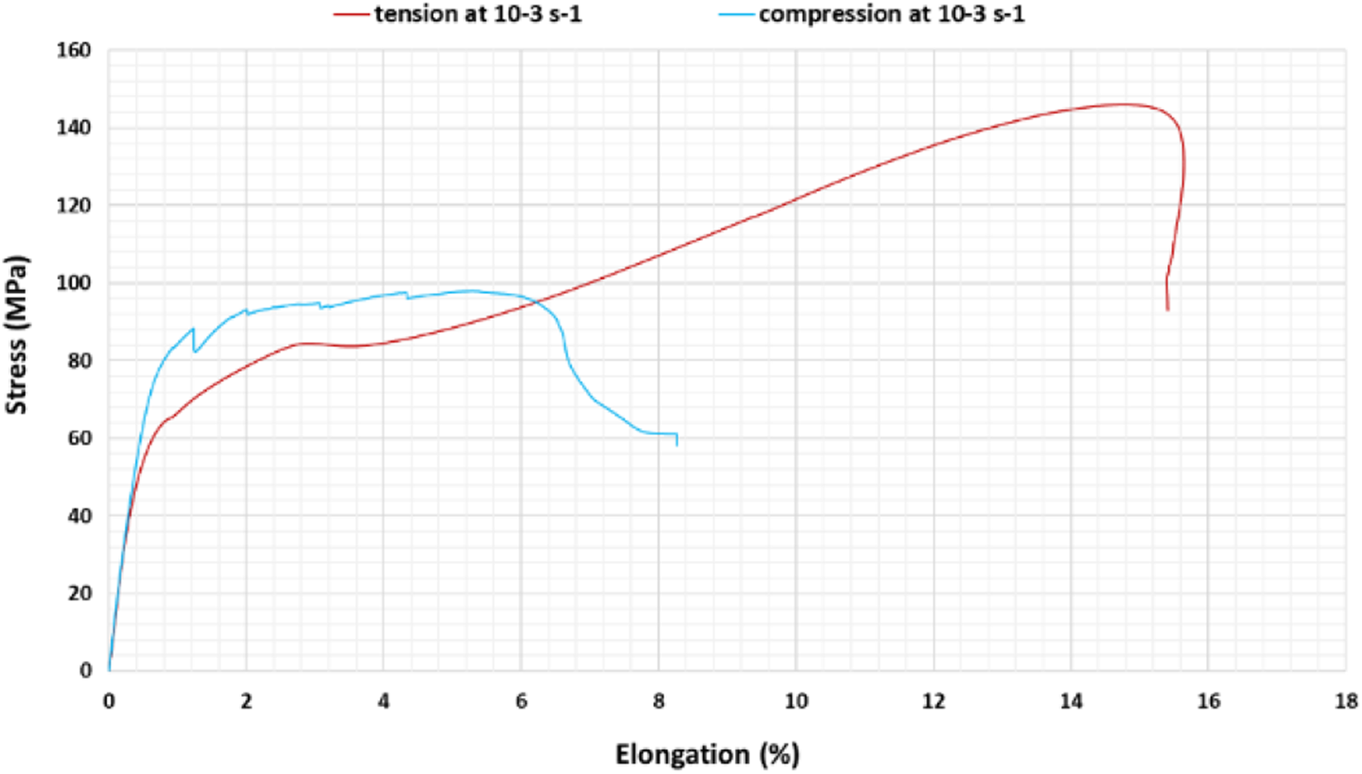
Mean responses of NCF ±45° laminated composite under tensile and compressive loadings.
Actually, to optimize the amount of absorbed energy, the couple stress/strain has to be maximized. The NCF version indeed offers an interesting stress level and an important strain grade. The combination of multiple kinds of fractures (delamination, fiber buckling, fiber/matrix debonding, fiber break, matrix crack, etc.) responsible of this plateau of pseudoplasticity finally permit to absorb an important amount of energy, equal to the area under the force/displacement curve.
Numerical model
All the parameters obtained have been used to build a numerical simulation based on the continuum mechanics model created by Johnson 17 and implemented by a subroutine in Abaqus v6.14 software. This model is an elastic plastic fabric failure model that accounts for in-plane shear damage. The fabric-reinforced composite ply is assumed a homogenous orthotropic elastic material. The failure of composite is the resulting of progressive degradation on loading by microcracking up to the ultimate fracture. Multiaxial failure criteria are incorporated by setting the element stresses to zero once the failure envelope is reached, even if the other damage states are not reached. The shear response in the model is dominated by the nonlinear behavior of the matrix, which includes both plasticity and stiffness degradation due to matrix microcracking. So, matrix plasticity only exists in shear and is not taken into account in the two main directions. The plasticity of the used resin is very low in the two main directions, so the plasticity in these two directions can be neglected.
To represent the pseudoplasticity of the composite from shear loading, a hardening function of stress with the following form is used

where
This pseudoplastic law is obtained from the damage of a ±45° laminate during charge–discharge tensile tests. From the values of each cycle slopes, the damage parameter d12 and the plastic deformation
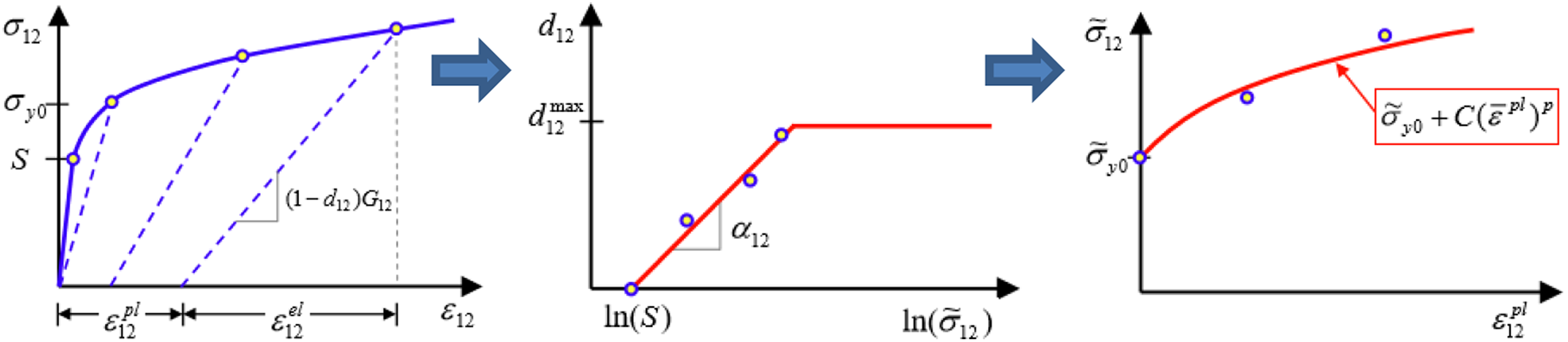
From d12, the stress parameter

Then, the curve representing the evolution of d12 as a function of
Finally, from the extrapolation from a power law of the evolution of
Nevertheless, this model neither represents the delamination of composite plies nor the strain rate sensitivity. In fact, this model is modified in another study, in particular to improve its accuracy and take into account delamination and strain rate. 19 However, its sufficient accuracy allowed us to simulate tests at scale 1:1 on absorbers with too complexed sections to be manufactured at low cost.
Once the material characterized, the main phase of tests debuts to compare NCF square and circular section tubes manufactured by an RTM process with a flexible membrane and aluminum absorbers (used as references).
Test methods for tubular structures compression
Quasi-static tests are easier to realize and allow the understanding of the crash response directly during the test. However, to check the effect of deformation rate on the global behavior of composite absorbers and on the SEA measured, dynamic tests will also be ruled.
On the ZWICK Z250 machine, quasi-static compressive tests have been ruled on these structures to measure the amount of energy absorbed during the test and compare the behavior of the tubes.
Dynamic compressive tests are carried out on the ZWICK AMSLER HTM 160-20 high-speed testing machine (Figure 5). The speed of the moving plate is controlled at the input and set at 20 m s−1 (an average deformation rate of the order of 102 s−1 ) to simulate a shock during an automobile accident. To check the different phenomena of fractures during tests and to measure precisely the real deformation, a high-speed camera GOM is used to take up to 30,000 pictures by second of the specimen. A correlation processing of pictures is realized with GOM Correlate 2016 software by GOM company through the tracking of the movements of the points of a speckle pattern (Figure 5) previously painted on the absorbers structures. Since the speed of impact is fixed by the displacement of the mobile plate, the precise deformation rate in the sample is also checked by the correlation of images.
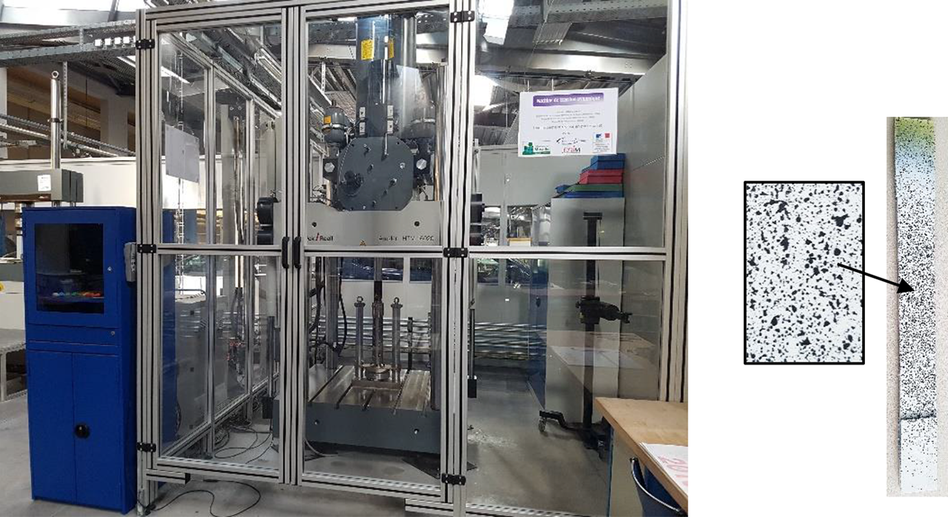
ZWICK Amsler HTM 160-20 high-speed testing machine (left) used to test composite specimen with a painted speckle pattern for digital image correlation (right).
The numerical model is checked with the experimental results and is then used to simulate the responses of too complexed section structures to be manufactured at a reasonable cost.
About the use of triggers, in the same quasi-static conditions on the ZWICK Z250 testing machine, quasi-static tests on the same NCF circular absorbers coupled with conical trigger are realized to improve the measured SEA.
Results and discussion
Experimental comparison of square and circular section absorbers at quasi-static loadings
Figure 6 illustrates the different phases of ruin of the absorbers during quasi-static compressions. At the macroscopic scale, the first phase corresponds to an initial peak of high stress when the square or circular absorber is brought into contact with the impactor plate.
Circular (a) and square (b) section NCF ±45° composite absorbers responses under compressive quasi-static loadings with aluminum solution reference (c).
During the loading of the specimen, a swelling of the walls appears (interlaminar delamination and debonding between fibers and matrix) resulting in a main rupture (fractures of fibers and matrix), responsible for the drop-in resistance of the piece. For the circular section, the swelling leads to a major circumferential rupture of the absorber (Figure 6(a)). For the square section, this swelling involves four major breaks in the corners of the specimen. Indeed, the right angles of the specimen play the role of triggers and correspond to zones of over-stressing. These fragile areas are thus more easily solicited during the swelling of the absorber and undergo a significant brittle fracture (Figure 6(b)). Then, the absorber is damaged gradually by mixed mode of brittle fracture: due to interlaminar delamination and major fiber breaks, the four walls of the square section and the circular one “fold” and fragment (mixed mode of brittle rupture is preponderant). This phenomenon continues until the compression of the remaining material debris, responsible for a rapid increase in the resistance of the sample (after about 110 mm of displacement). This increase is not interesting in terms of shock absorption because it implies a further significant deceleration suffered by the passengers of the vehicle. We therefore consider the absorptive capacity of these absorbers up to 110 mm of displacement (on the 140-mm total length of absorber). Figure 6 also recalls the behavior of the aluminum reference specimen, which is more stable than composite solutions due to the progressive formation of lobes during compression (Figure 6(c)) but which has a lower effective length: 85 mm of displacement before the incompressibility of the remaining material.
From the point of view of energy absorption by composites, this overall behavior does not absorb the shock optimally for the safety of passengers. It is indeed necessary to reduce the initial peak by decreasing the value of the “peak force value”/“force plateau value” ratio (currently equal to 4) we will now call load efficiency. In addition, after the initial break, the absorber is too damaged and presents a resistance too low to consume an interesting amount of energy.
In conclusion about the type of section, the circular geometry seems more interesting in the state than the square section. The formation of breaks in the corners of the square section makes it possible to absorb an interesting quantity of energy, but their fast propagation along the corners implies an early failure of the specimen: The final SEA is lower than the aluminum specimen one. The size being fixed (outside diameter and width defined at 90 mm), the square section has a larger area but the amount of energy absorbed per unit of material is smaller than the circular solution one. The circular section has indeed a mechanical strength/weight ratio more interesting and therefore allows to achieve an SEA close to the aluminum reference solution, even if its overall behavior is similar to the square solution. However, a not insignificant advantage of the square section is to allow the prediction of the zones of initial breaks. The exact area of the initial failure for the circular absorber is, on the contrary, difficult to predict.
Finally, these sections exhibit an absorption behavior far from being as efficient as the aluminum absorber. Indeed, thanks to its plastic deformation and the regular creation of lobes, the energy absorption of the aluminum version is more regular and has a rather low load efficiency (near 1.3). Nevertheless, the advantage of the square section and the absorption performance of the circular solution demonstrates the advantage of the use of composites for shock absorption and therefore deserves optimization of the specimens.
Validation of square and circular section absorbers responses at dynamic loadings
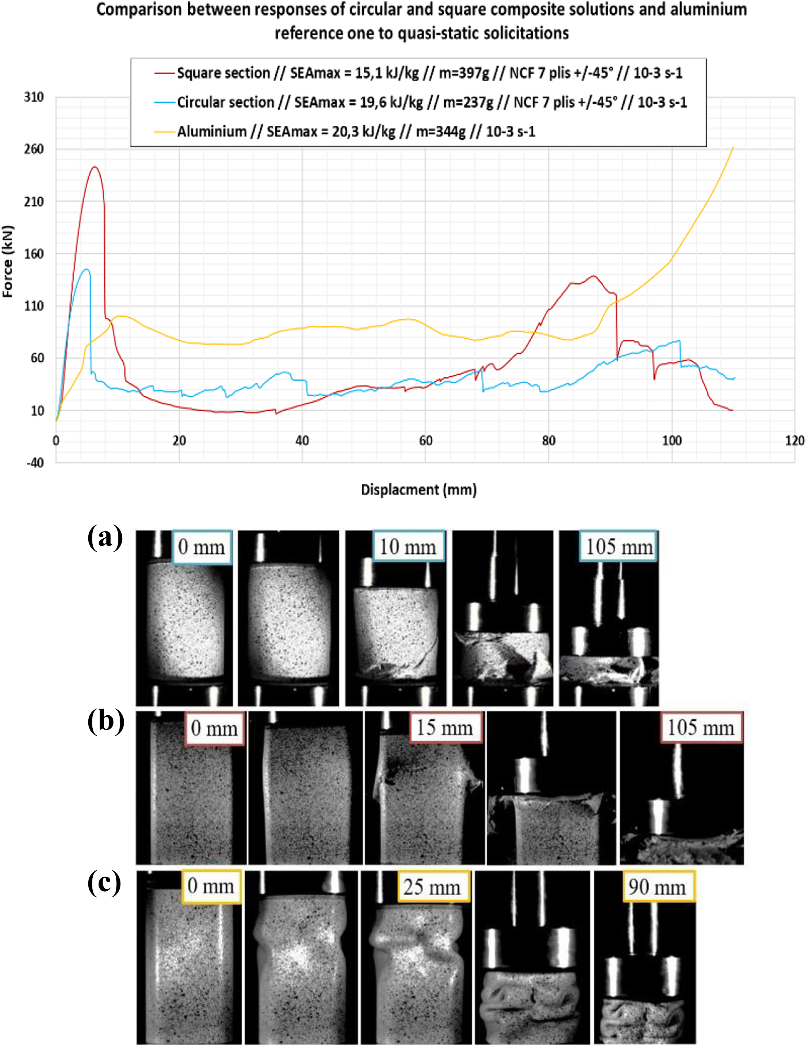
As the final objective is to use this material as shock absorbers for automotive, it has been decided to test the NCF ±45° 7-plies circular and square absorbers under dynamic conditions. It is important to note that the force sensor used on the ZWICK HTM 160-20 is limited to 100 kN: A saturation is then observed on the dynamic responses of the samples when the compressive strength reaches 100 kN. Figure 7 illustrates the respective difference in crash response of circular and square section absorbers under quasi-static and dynamic loads. The aluminum solution is tested under the same conditions to reflect the performance to be achieved.
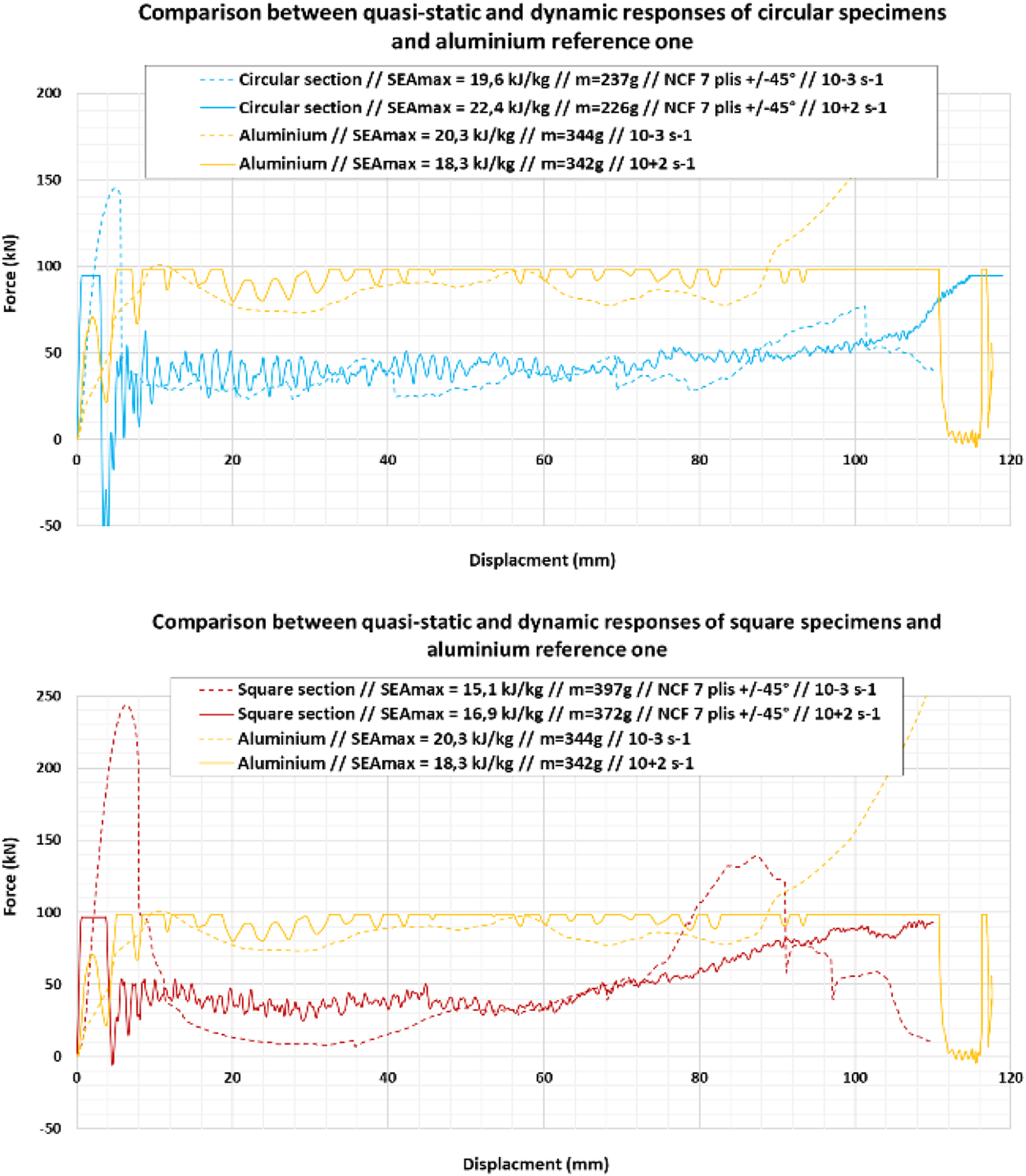
Effect of deformation rate on circular and square section NCF ±45° absorbers with aluminum reference.
In terms of behavior, the embrittlement of the material is reflected in Figure 7. However, in terms of energy absorption, this stiffening does not significantly alter the amount of energy absorbed and can be neglected in this study. Moreover, after the first break, the damage behavior is more regular in dynamics. The stressing speed weakens the NCF material [±45°], in particular the matrix, 20 and promotes significant interlaminar delamination. Indeed, as mentioned in the study on the material, the interlaminar rupture resistance decreases with the increase in the deformation rate: The propagation of cracks by delamination between plies is favored. 21 –23 At the macroscopic scale, these phenomena lead to a change of failure mode: The main mode of brittle fracture in quasi-static evolves toward a principal splaying mode in dynamics. 24
The images obtained with the high-speed camera in Figure 8 confirm a compression by splaying mode mainly rather than by mixed mode. This dynamic crushing of the composite structures is more regular than during quasi-static loadings which present major break phases during the brittle fracture mode. Figure 8(a) illustrates the crushing of the aluminum reference absorber. The response of the specimen is similar to its response under quasi-static stress with the formation of different lobes.
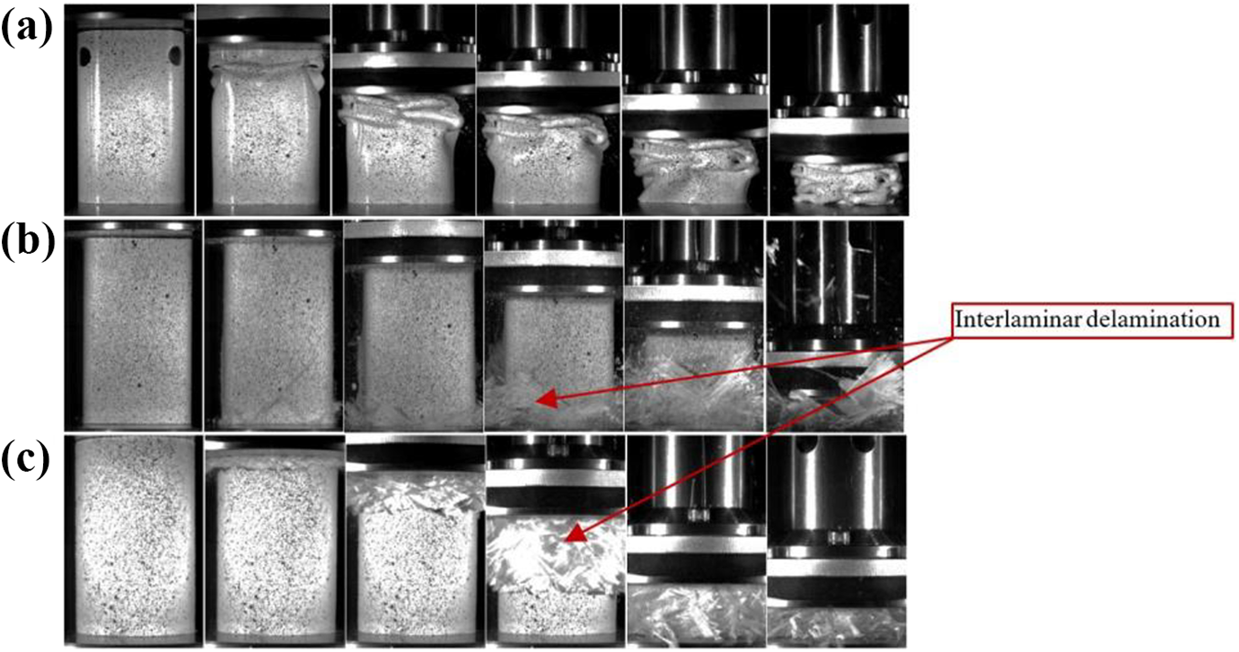
Compressive tests at 20 m s−1 on: (a) aluminum solution, (b) square section absorber, and (c) circular section absorber.
For composite absorbers (Figure 8(b) and (c)), the pictures appear to confirm smoother crushing. The swelling of the structure during the contacting is less visible during these dynamic tests. The splaying mode is observable for both types of sections where an interlaminar rupture separates the walls of the composite into two sets. These sets of plies then fold over themselves throughout the crash (fourth images) and the compression continues until the compaction of the piece. However, the embrittlement of the material does not modify the mean value of the force plateau: The area under the curves seems similar for the different deformation rates. Even if the mode of rupture changes according to the deformation rate, the values of SEA are similar whatever the speed of the shock. Nevertheless, the performance of composite systems to effectively absorb dynamic shocks without endangering passengers is insufficient. Such as the responses to quasi-static loadings, the amount of energy absorbed is interesting but it is necessary to suppress the presence of the initial peak while maintaining the most stable plateau possible throughout the shock. It is therefore important to study other more complex geometries that allow more effective control of the ruin of a material favoring a low load efficiency and a maximized SEA.
Numerical study of complexed section absorbers
Before testing different sections, the continuum mechanics model must be validated through a comparison with experimental results. Figure 9 reflects the accuracy of the model to simulate the impact of a circular section absorber under quasi-static loading. The numerical model overestimates the resistance and so the SEA (+7% for the numerical SEA) of the real specimen: This error can be explained by the geometrical defaults of the real specimen (variation of wall thickness due to the flexible membrane) but also, because the actual model doesn’t take into account delamination, a less energy-consuming phenomenon than fiber fracture. However, the accuracy of the model is sufficient to correctly simulate and compare the overall behavior of different kinds of sections.
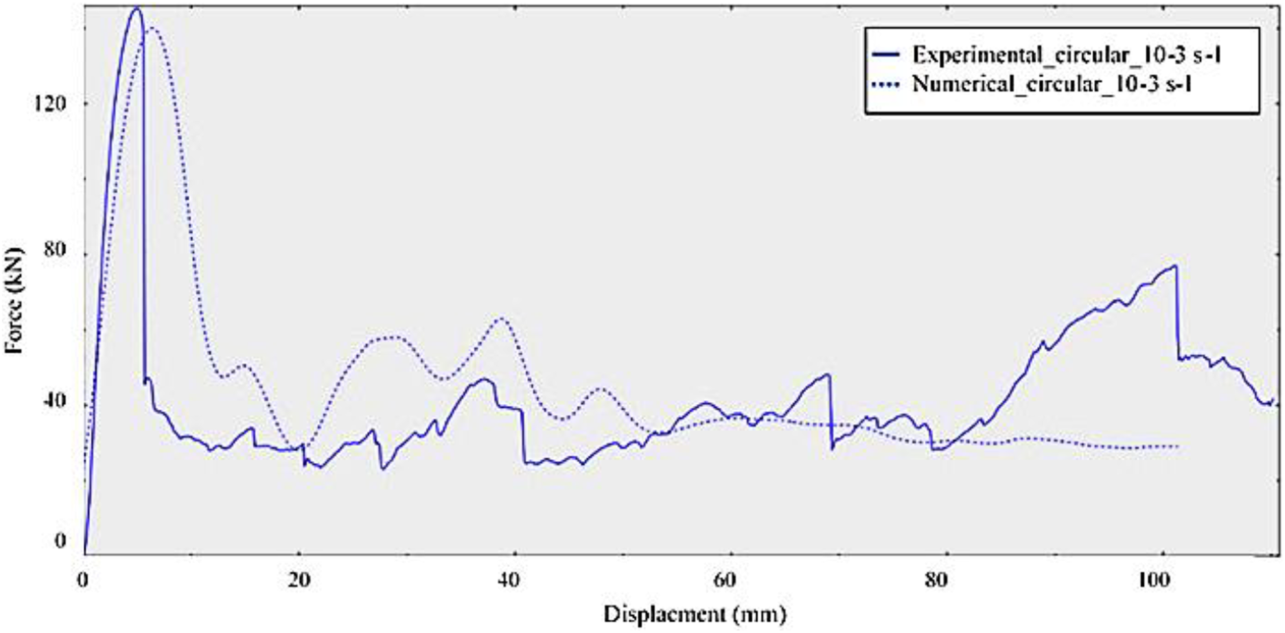
Comparison between the experimental response and the numerical simulation result of an NCF ±45° 7 plies circular section absorber under quasi-static compression.
In view of the numerical results of this validation step, a comparative study of new sections can be initiated to optimize the geometry improving the ability of the material to absorb the energy released during the impact. Indeed, this will allow us to improve our understanding of the effect of the section on the overall energy absorption behavior of the specimen. Although the experimental study was able to show a higher amount of energy absorbed for the circular section, the square section test allowed us to observe the role of right angles. Indeed, the lack of energy absorbed compared to the circular section is mainly due to the flanks of the square which undergo only little damage during the crash while the corners consume the vast majority of the final energy.
The choice of sections for the numerical simulation was based on the modification of the “basic” sections (circular and square) to maximize the damage of the material and to optimize the areas of breaks. Figure 10 shows the different sections tested numerically. The size of the sections is fixed by the allowable space requirement (90 mm space) and an NCF 7-plies laminate oriented at ±45° is used.
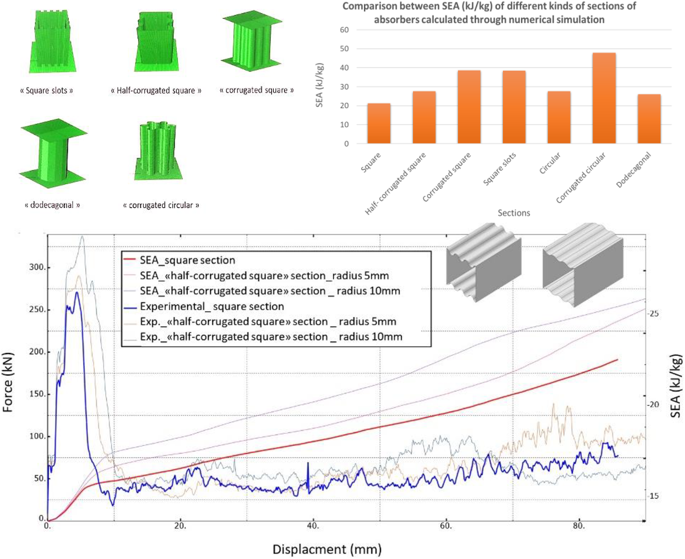
SEA values of different sections obtained with the numerical model: example of the numerical crash response of an NCF ±45° 7 plies “half-corrugated” section absorber under quasi-static compression.
Unfortunately, no tested section improves the overall absorption behavior and presents similar responses to the square and circular sections: after a high initial peak, a more or less stable plateau of force is observed before compression of the rest of the sample. Figure 10 shows an example of this type of crushing behavior by illustrating the response of the “half-corrugated square” section according to two radius values for the corrugations.
Despite the improvement of the SEA compared to the one of the basic square section (40% more), the value of the load efficiency too high (in the order of 5) and the lack of regularity in the “plateau” zone are observed on the half-corrugated square sections. The same conclusion can be drawn on all the geometries tested. Figure 10 illustrates the increase in the value of SEA for the different sections studied. Indeed, the use of complex sections makes it possible to significantly increase the value of SEA: The use, for example, of corrugations on the walls of the square and circular sections (but also of crenellations) makes it possible to simulate the action of the right angles in the crash of a square section while increasing the number of principal breaks: The value of the SEA is increased up to about 80% compared to the “simple” square and circular sections.
Nevertheless, the very interesting values of SEA are not sufficient to compensate for the initial crushing behavior of these sections, coupled with the difficulty of producing these unconventional geometries. The use of corrugations, crenellations, and so on, which improves the number of breaks (and therefore the SEA) does not alter the significant resistance offered by the absorber during the first contact (high value for the load efficiency). It therefore seems better to use internal or external triggers to try to reduce the first shock and allow the smooth progressive crash of the absorber.
Study of the effect of a conical trigger
Like Thuis and Metz illustrate the performance of triggers, 25 an external base concept in conical form (Figure 11) was tested as a trigger to reduce the initial contact area and create circumferential stress (by reducing the diameter) regularly during the crash. 26 It is important to note that the use of this trigger makes it possible to consume the entire length of the absorber, that is, a useful length of 140 mm against the 110 mm consumed during a composite absorber “standard” compression. However, in the lab conditions, the tests are stopped earlier (≈80 mm of displacement), once the plateau of force stabilized, in order to avoid any damage to the structures of the test machine. Figure 11 illustrates the compression of the absorber inside the conical base. During the test, the absorber is forced inside the cone and the imposed change of diameter causes constant damage to the specimen during the crash.
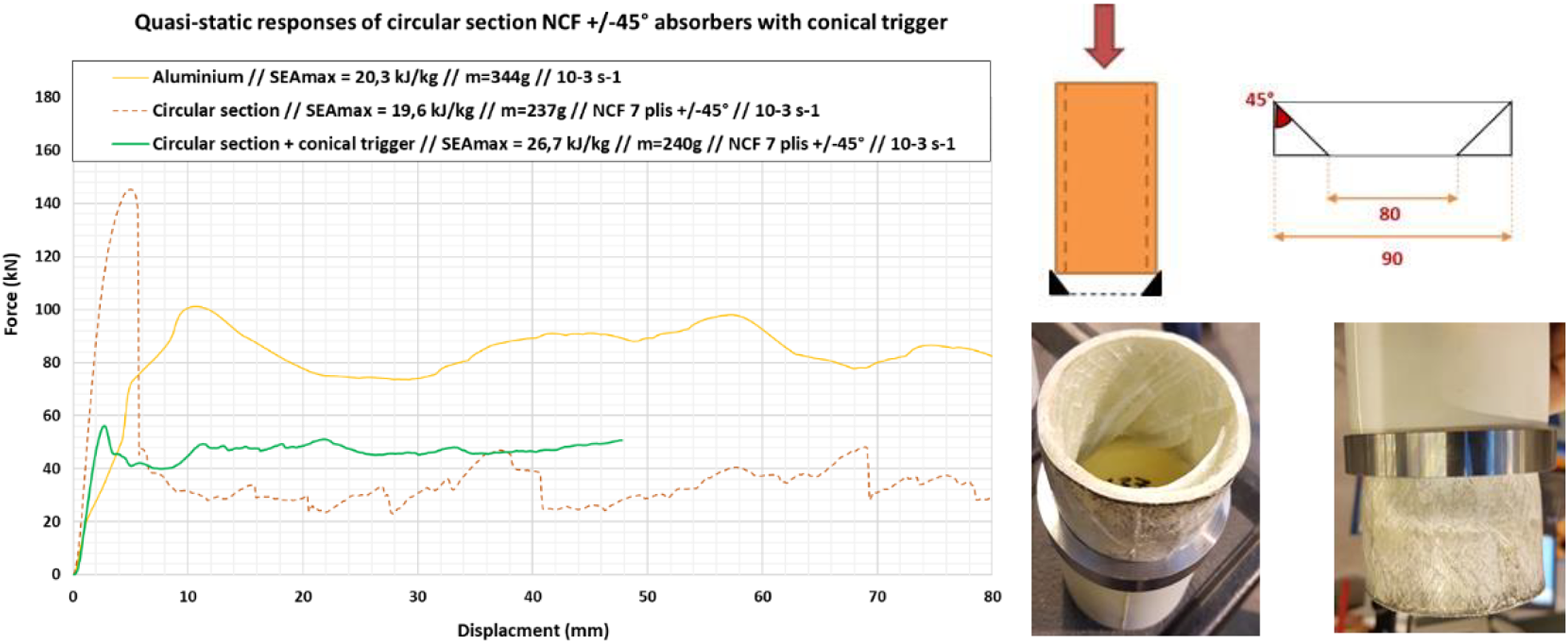
Experimental response of the compression of the circular section absorber with conical trigger.
Figure 11 shows the quasi-static compression response of an NCF ±45° 7-plies absorber with the “conical base” trigger. The response is very interesting in terms of behavior despite a “simple” section geometry of absorber.
Precisely, the initial peak is very low during contact. Indeed, the progressive contact between the absorber and the conical base limits an increase in the measured charge. Moreover, the progressive and stable failure mode in this case begins earlier: from the first contact, the new diameter imposed by the conical trigger brings an important interlaminar delamination allowing the sliding of the laminate plies. This constant phenomenon goes on until the end of the test, whereas, for compressive tests on absorbers without triggers, the uncontrolled progressive crush by brittle mode occurred after an initial break and ended early because of the difficult compression of the remaining debris of composite. With the use of this conical trigger, once initiated, the compression is quite regular and so allows to absorb a quantity of energy higher than the SEA found on the simple compression of the same absorber: 26.7 kJ kg−1 for “conical base” concept against 19.6 kJ kg−1 for “standard” compression. Anyway, the objective fixed by the aluminum reference (SEA = 20.3 kJ kg−1 ) is exceeded by the use of the trigger. The stability of the global crash response of the couple composite absorber/conical trigger is similar if not better than the performance of the metallic solution thanks to the controlled failure mode imposed by the trigger.
Conclusions
As we have seen it in this study, the NCF presents an interesting high-level couple stress-deformation. Thanks to the number of different fractures and the level of deformation, the absorption of energy during compression of the material is quite important. The geometry of the specimen has to let the full potential of this material. The “simple” square section brings macro-ruptures since the start of the test and the specimen is rapidly ruined. New kinds of sections have been investigated numerically and show greater amounts of absorbed energy. However, such as circular and square sections, their global responses to crash don’t respect automotive criteria in particular absorbing energy constantly all along the crushing. Regarding these results, the use of a conical trigger has been studied. The crash behavior is more stable and introduces a low value of load efficiency while absorbing a higher amount of energy than circular “basic” section. A new study has begun to optimize the number of plies of the laminated composite to maximize the SEA with the use of a trigger (conical or another type) while improving the value of the load efficiency and the stability of the crash response.
Footnotes
Funding
The author(s) disclosed receipt of the following financial support for the research, authorship, and/or publication of this article: The authors acknowledge the help of project COMPAS funded by the REGION GRAND EST and the EUROPEAN UNION as part of the operational program FEDER FSE LORRAINE et Massif des Vosges 2014–2020 in partnership with REHAU, Institut de Soudure and CINI for their support of this work.