
Abstract
Induction heating or welding can be performed by considering the combined effect of ferromagnetic heating due to magnetic hysteresis losses and eddy current heating due to conductive material. Nonconducting thermoplastic composite parts can be joined or welded by induction heating using a susceptor sheet filled with nickel-coated carbon fibers (NiCCFs) and nickel-coated graphite particles (NiCGPs) or both with polypropylene (PP) thermoplastic matrix. Above the percolation threshold, NiCCFs can serve as conductive materials and nickel coating will provide the ferromagnetic heating. NiCCF/PP and NiCCF/NiCGP/PP susceptor sheets were developed via melt mixing using a twin-screw extruder and sheets were produced by Calendering process. Induction heating tests were performed on a circular pancake coil and at frequencies below 1 MHz. In induction heating, fiber heating by Joule loss, junction heating (i.e. dielectric heating and contact resistance heating), as well as magnetic hysteresis effect were observed in both the cases. Heating in hybrid filler was higher at lower filler concentrations; however, with higher concentrations, heating reduced. Reduction in induction heating maybe due to a reduction in electrical conductivity was observed. Electrical conductivity was measured in fibers direction by a Keithley electrometer using a four-point measuring method and temperature was measured by an infrared thermal camera. Microstructure characterization was performed by X-ray computed microtomography and light microscopy.
Introduction
With the advances in manufacturing technologies, thermoplastic composites have attracted many industries due to lightweight, high stiffness and strength, good fatigue resistance and corrosion resistant, as well as short processing time. 1 –4 Joining of thermoplastic composites has been carried out by conventional methods. Mechanical fastening and adhesive bonding are conventional methods of joining; however, they have certain disadvantages. 5,6 In mechanical fastening, the addition of extra weight, stress concentration, delamination during drilling, different thermal expansion of composite materials and fasteners, and corrosion due to water intrusion are the main drawbacks. Further to these, extensive labor and time is also required. In adhesive bonding, it requires extensive surface preparation, long curing times, and difficulties for bond formation to thermoplastic matrix. 7,8 Fusion bonding is the joining of thermoplastic components by fusion 1 and consists of five steps such as surface preparation, heating, pressing, diffusion, and cooling. Heat can be generated at joint interface by different means; therefore, fusion bonding techniques are classified on the basis of heat introduction at interface. 9,10 These are bulk heating, frictional heating, electromagnetic heating, and two-stage techniques. Induction heating is a subclass of electromagnetic heating, where heat can be obtained by exposing the material to induction field created by a coil. The field generates eddy currents in the conductive materials and heating occurs due to Joule losses.
Joining by induction heating is a contactless joining process that can join fiber-reinforced thermoplastic composites, as well as dissimilar thermoplastics and thermoplastic to non-thermoplastic composites. 11 –13 It can be automated to fulfill the industry requirement for a fast and reliable method for product manufacturing. Induction heating or welding uses flow property of thermoplastic when heated above their glass transition temperature or melting point. Bonding of composites by induction heating consists of heating followed by melting, flow, and consolidation. Joining in case of nonconducting or nonmagnetic materials thermoplastic, an additional susceptor sheet is required.
Induction heating is a simple phenomenon. In induction heating, alternating electromagnetic field is placed near ferromagnetic and conductive materials; heat is produced by magnetic polarization effect and eddy currents in magnetic and conductive materials, respectively. 14,15 Therefore for nonconductive or nonmagnetic materials, a medium is required that has one or both the properties; however, heat energy generated by eddy currents is higher than magnetic hysteresis effect. 16 Heating in conductive fibers took place due to three mechanisms simultaneously occurring, that is, Joule losses, 17 dielectric heating, 18 and contact resistance heating 19 ; however, ferromagnetic particles heat due to magnetic hysteresis loss. 20 An added advantage of ferromagnetic particles is the Curie temperature. At this temperature, heating stops automatically where material becomes paramagnetic. 21 This is automatic cutoff at certain temperature; however, only few commonly available susceptor particles have melting range of thermoplastic. 22 –24
A susceptor sheet that fulfils the following requirements can be used for induction heating. The susceptor sheet with electrical properties heating can be obtained by eddy current unless they form closed electrical conductive loops, like carbon fabric, and ferromagnetic particles filled sheet can generate heat by magnetic losses. If short carbon fibers are used, that should achieve the percolation threshold. Contrary to short carbon fibers, multiwall carbon nanotubes can achieve the percolation threshold at lower weight fraction; however, they don’t form conductive loop. 19 To increase the electrical conductivity, carbon-based fillers, 25,26 metallic fillers, 27 –29 metal-coated fillers, 30,31 and combination of fibers and particles 32,33 as well as effect of processing 34 were investigated. Metallic-coated fillers have various advantages like metals having high electrical conductivity as well as good thermal conductivity. During induction heating, they can also give heating due to magnetic hysteresis. Thermal conductivity is another aspect of homogeneous heating. For high thermal conductivity, high filler loading of particles required. 35 However, synergistic effect of different carbon fillers also gives good thermal conductivity. 36
Particles 19,20,37 and fibers 38,39 are being used by various researchers to obtain fast heating that will be able to melt the thermoplastic matrix. Baryel 19 investigated iron particles and found that particle size of 25–62 µm was excellent in heating; however, nickel particles of same range were too slow in heating. Zhang et al. 40 investigated the ferrites with different filler concentrations of nickel and zinc. Hysteresis losses were only the source of heating as high resistivity of ferrites didn’t allow eddy current losses. Fibers were also used for induction heating and most of the work was performed using unidirectional prepreg materials 41,42 ; however, 0/90° layups of unidirectional prepreg materials have high heating. 18,43 In prepreg materials, number of plies, interface, and ply thickness are critical. High electrical contact between crossed plies and Joule heating in fibers was observed and reported by Miller et al. 17 ; however, during the layup process, different layers of fibers were used that created dielectric effect and heating obtained by dielectric losses. 18 Dielectric losses were reported by Fink et al. Yarlagadda et al. 43 observed fiber heating as a dominant mechanism, because of the low contact resistance, fiber structure, and its type. Kim et al. 41 observed the junction heating as a dominant mechanism and high heating can be achieved with available high fiber junctions.
Induction heating can be performed using ferromagnetic particles below the percolation threshold, 20 where magnetic hysteresis loss is the heating mechanism; however, due to low aspect ratio, particles concentration should exceed above 33 vol.% 44 to achieve percolation. Various researchers have worked with different ferromagnetic particles; however, only few particles have melting range of thermoplastic with respect to the Curie temperature. On the other hand, the use of alloys by doping and modification of the processing route can help to influence the heating and Curie temperature. Different particles of micrometer 19 and nanometer 45 sizes, as well as different ferrite particles 40 were used to obtain better heating.
The objective of this work was to investigate the metal-coated short fibers along with metal-coated hybrid fillers (i.e. nickel-coated carbon fiber (NiCCF) and nickel-coated graphite particle (NiCGP)) filled thermoplastic susceptor sheet for induction heating application. The present work will not only give better understanding of all four heating mechanisms but also conductivity-based heating.
Experimental
Materials and manufacturing process
Polypropylene (PP; Moplen HP 400 R) thermoplastic, from LyondellBasell Company, was used as matrix. It has melt flow index (MFI) of 25 g/10 min and a density of 0.90 g/cm3. Two different fillers were used: one was fiber and second was particles. Both of these fillers were nickel coated. Fibers were purchased from Toho Tenax Co., Europe GmbH of grade Tenax®-J HT C903. They have the following properties, that is, a length of 6 mm, a diameter of 7.5 µm, and a density of 2.70 g/cm3. Coating thickness of nickel on fibers was 0.25 μm. NiCGPs were purchased from Lomberg GmbH. They were 90 μm in diameter, having a density of 3.8–4.0 g/cm3. Nickel coating on graphite particles was 60%.
Compounding was carried out using a double screw extruder (ZE25A X 44 D; from Krauss-MaffeiBerstorff GmbH). Melt mixing technique was used to mix fibers (NiCCF) and particles (NiCGP) together with the PP matrix as mentioned in Table 1. Sheets were produced by the Calendering process. Approximately 500 μ thickness sheets were prepared using an optical films from (Dr. Collin GmbH) machine. Various compositions were prepared using fibers (NiCCF) and particles (NiCGP). The processing parameters were kept the same; they were processing temperature of 220°C, the screw rotation speed of 300 r/min, and the throughput of 9 kg/h. A main feeder was used for feeding PP granules; fibers (NiCCF) and particles (NiCGP) were added by a side feeder by the controlled gravimetric dosing system. Vacuum was applied at the end of the polymer melt to avoid porosity. The NiCCF/PP and NiCCF/NiCGP/PP melt directly falls on the Calendering rollers. They form into thin sheets and rolls were produced by collecting into big rolls.
Filler concentrations and their notations.
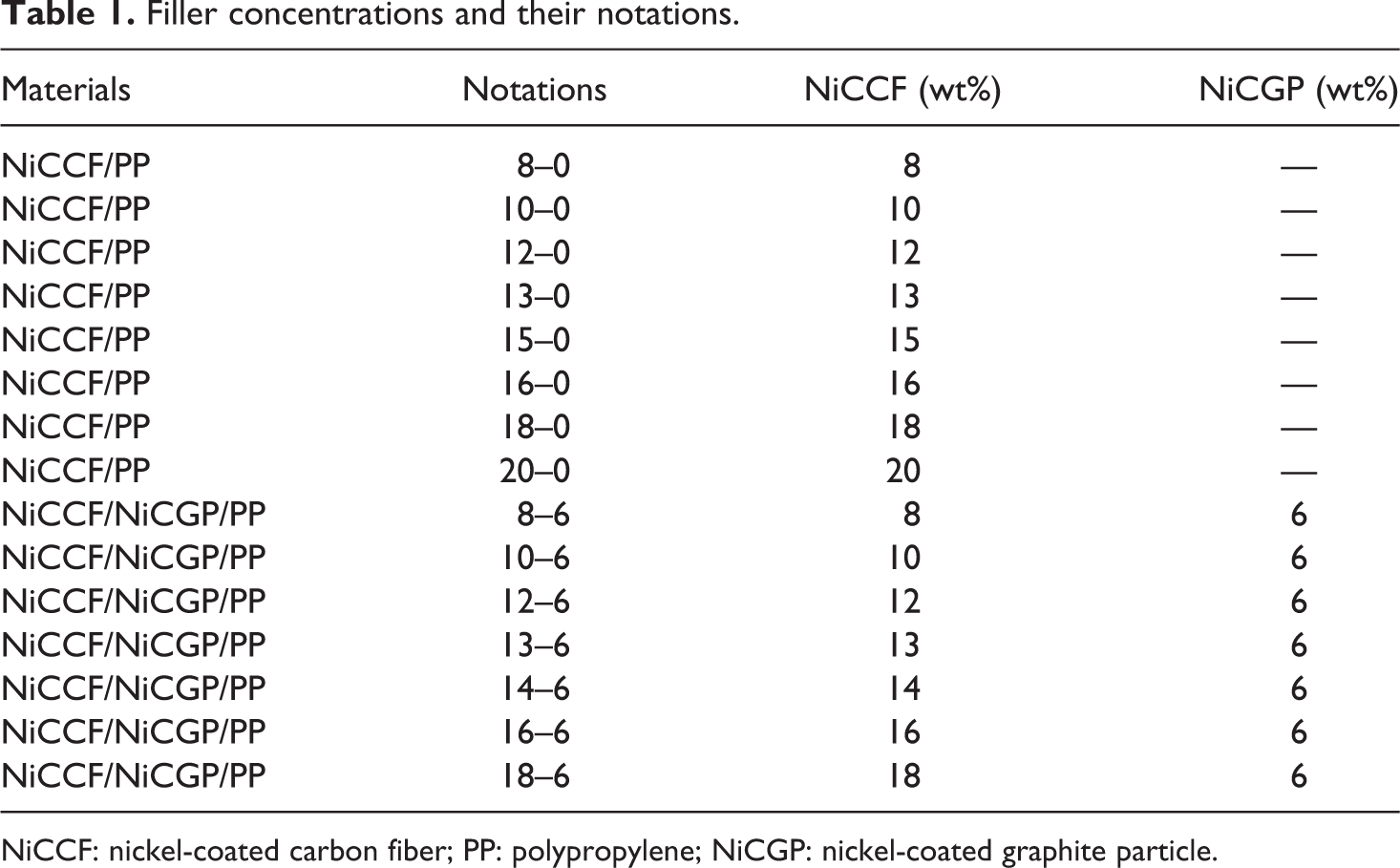
NiCCF: nickel-coated carbon fiber; PP: polypropylene; NiCGP: nickel-coated graphite particle.
Characterization
Electrical properties
For electrical conductivity measurement of NiCCF/NiCGP/PP sheets, the four-probe testing method was used and determined according to DIN EN ISO 3915 (1999). A Keithley 2601A electrometer was used, and in a four-probe test setup, two electrodes were for power supply and two for measuring potential difference. Rectangular samples of having dimensions of 30 × 10 × 4 mm3 were used after grinding and polishing. Blocks were prepared by stacking sheets and hot pressed, later on rectangular sample was prepared by cutting on a band saw. Silver paste was used to reduce the contact resistance. The resistivity of the samples was measured and the volume-specific conductivity was calculated by
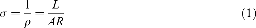
where ρ is volume resistivity (Ω mm), R is measured resistance (Ω), L is the distance between electrodes (mm), A is a cross-sectional area (mm2), and σ is volume conductivity (Ω−1 mm−1). Five samples were tested and the average value of the resistivity in parallel direction (i.e. longitudinal, sheet processing direction from Calendering) was obtained. Later on, conductivity was calculated from equation (1).
Induction heating properties
Induction heating experiments were carried out by the locally developed test setup. It consists of a generator, a capacitor box, and a pancake coil. Generator (Hüttinger TruHeat 5010 MF) was purchased from TrumpfHüttinger, Germany. Generator maximum current was 35 A that transformed to a coil circuit current of 280 A. Changeable capacitors with different frequencies were used. Pancake circular coil with a diameter of 100 mm and a thickness of 6 mm with an internal water cooling system was used. NiCCF/PP and NiCCF/NiCG/PP composite sheets of 120 × 120 mm2 were placed at a coupling distance of 2 mm. By selecting different frequencies using different sets of capacitors, induction testing was performed.
Morphological properties
For the distribution of fibers and particles, X-ray computed microtomography scans (micro-CT) were performed. A commercial micro-CT machine from nanotom by Phoenix X-Ray Systems, Germany was used. Micro-CT scan gives a three-dimensional image; therefore, the distribution of fibers and its dispersion within layers can be seen. Similarly, particle distribution can be seen in the composite sheets. Light microscopical analyses (Diaplan, Leitz, Germany) were carried out to observe macroscopically the fiber orientation and fiber length distribution of NiCCF and NiCCF/NiCGP, using digital images and analysis software (AnalySYS FIVE; Olympus GmbH, Germany). Scanning electron microscopy (SEM; Zeiss Supra VP40, Carl Zeiss SMT AG, Germany) was performed to obtain further morphological information. Before SEM analysis samples were coated with platinum–gold layer in a sputtering device (OerlikonBalzers, Liechtenstein).
Results and discussion
Electrical conductivity
In Figure 1, volume-specific electrical conductivity of NiCCF/PP and NiCCF/NiCGP/PP composites has been shown. 46 Conductivity was measured in fiber direction in both the filler concentrations. In the hybrid system, filler concentration of particles remained constant; however, filler concentrations of fibers increasing. Increasing trend of fiber will keep the properties of fibers dominant. The conductivity of hybrid filler (NiCCF/NiCGP/PP) increases by increasing the filler loading. For filler weight percentages (see Table 1), first digits show fiber concentrations and second shows particle concentration as weight percentage. In hybrid fillers, from 8–6% to 12–6% only a slight increase in conductivity can be seen. However, at higher loading, a sudden jump in conductivity was observed. Further increasing the filler loading above 14–6%, conductivity approached a plateau. The percolation threshold is in the range of 12–6% to 13–6% filler loading. Main issues related to the increase in conductivity are fibers and particles made an interconnected network in plane, and particles also helped to generate connections between the top and bottom layers of fiber. Other main reasons are metallic coating of fibers and high aspect ratio. The addition of nickel has an adverse effect on conductivity 33 ; however, a similar effect in decrease of conductivity was observed. The main reason for introducing the coated particles was to make better contacts between fibers. Due to the adverse effect of nickel, a small constant amount of NiCGP was used to keep the fibers properties dominant.
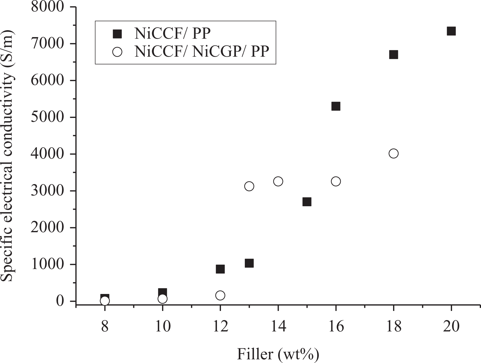
Conductivity versus filler concentrations of NiCCF/PP and NiCCF/NiCGP/PP composites.
The volume-specific electrical conductivity of the NiCCF/NiCGP/PP composites was significantly lower in comparison to NiCCF/PP composites. However, the percolation threshold was reduced from 15% to around 13–6%. The main issue related to the reduction in conductivity was particles due to high contact resistance.
Induction heating properties
Induction heating properties of NiCCF/PP and NiCGP/PP composites have already been published. 46 The heating effect of the NiCCF/PP composite was combined effect due to eddy current losses and magnetic hysteresis; however, for NiCGP/PP composites, heating obtained by magnetic hysteresis only, as particles were well below the percolation threshold. Induction heating of fibers–particles hybrid fillers was studied, using a constant amount of particles and fibers concentration was increased. Effects of changing the frequency of the electromagnetic field were studied as well as the influence of different microstructures of the sample.
(a) Effect of susceptor materials
In this study, fibers and fibers plus particles hybrid fillers were used; however, in hybrid filler, particles concentration was kept constant and fibers were changing. Induction heating tests were performed using Hüttinger generator with pancake coil. Initial testing was performed at lower frequency on both the filler polymer systems. Temperature was measured by an infrared (IR) thermal camera. Fibers were having a high aspect ratio, while particles have a low aspect ratio. From time temperature graph obtained from the IR thermal camera, first 10 s were selected to calculate the average temperature obtained in this time interval.
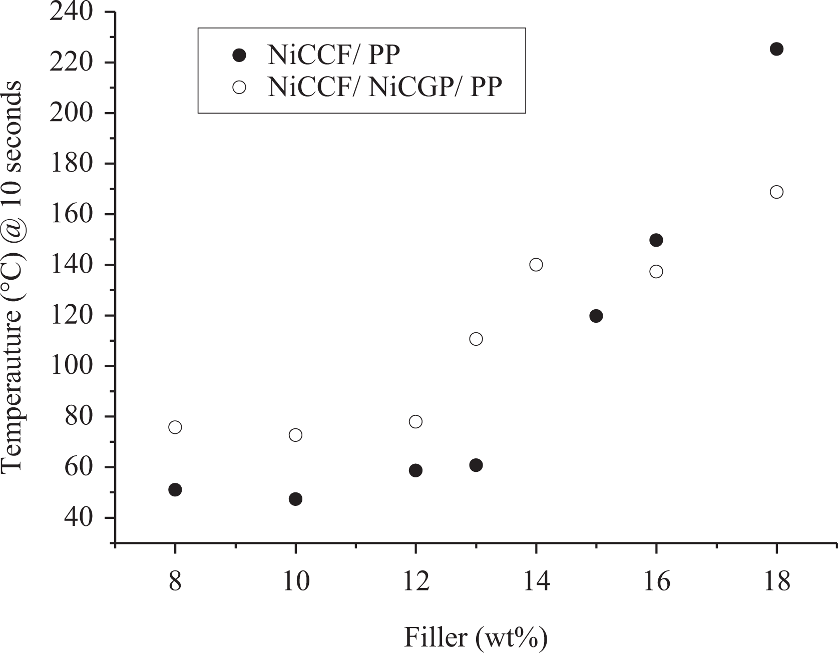
In Figure 2, filler versus temperature graphs for fibers and hybrid filler are plotted. The induction heating was performed at 30 A and a frequency of 273 kHz. Increasing the filler concentration increases the average temperature during selected time interval in both the filler systems. At low concentrations, hybrid filler is ahead in heating, while fibers were below during this time interval. This high temperature gain may be due to different factors. The addition of NiCGP particles contributes more heating from magnetic hysteresis effect and formation of additional contacts with the help of particles and junctions that heat generated due to contact resistance. Heating due to the formation of junctions at various points in a sample was observed. At higher concentrations, fibers are ahead in heating, while hybrid filler is well below. From the electrical conductivity results, it can be seen that the percolation threshold of fibers lies around 15%; however, for hybrid filler, it lies around 13–6%. The reduction in heat in higher concentrations in hybrid filler may be due to the close formation of junctions that behave as a single heating region or magnetic heating due to cluster formation. High heating may be due to the dielectric heating in hybrid filler at low filler concentration; however, at higher filler concentration, that effect has reduced. These three mechanisms, such as magnetic hysteresis, contact resistance, and dielectric hysteresis, change with filler concentration. The result shows that at certain filler concentration in hybrid filler, that is, 13–6%, percolation has achieved that did not support enough for heating at this filler concentration, as we have seen the reduction in electrical conductivity.
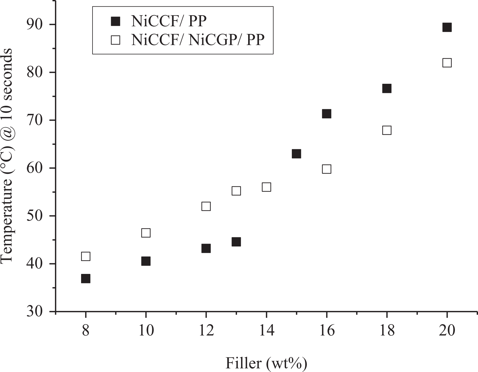
Effect of filler concentration on heating NiCCF/PP versus NiCCF/NiCGP/PP, tested at 30 A and 273 kHz.
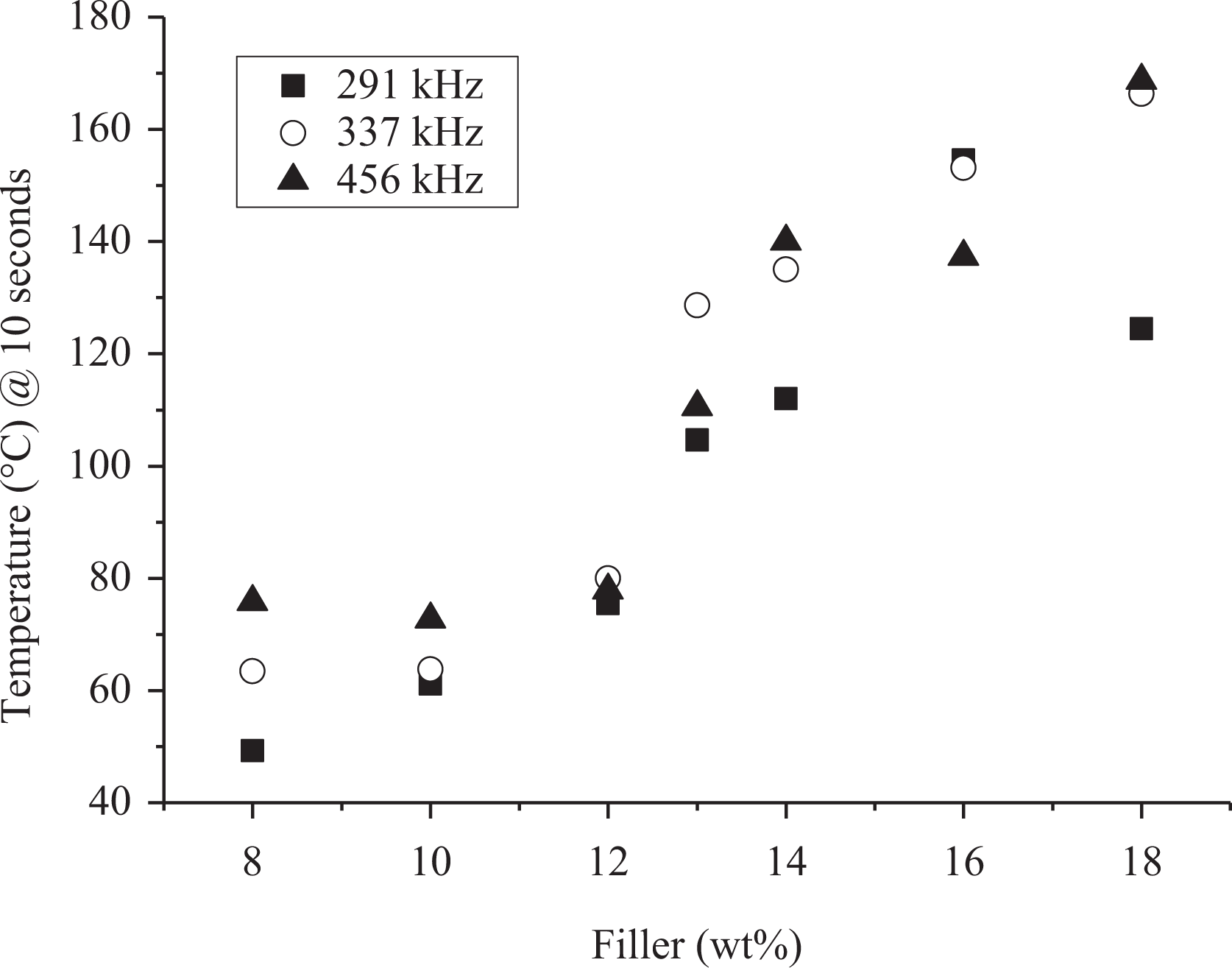
In Figure 3, filler versus temperature graphs are plotted. Fibers (NiCCF) and fiber plus particles (NiCCF + NiCGP) samples were tested at 30 A and a frequency of 456 kHz. Temperature is taken in the first 10 s of induction heating. Two different concentrations of fibers and hybrid filler were compared.
Effect of filler concentration on heating NiCCF/PP versus NiCCF/NiCGP/PP, tested at 30 A and 456 kHz.
In the heating pattern of NiCCF/PP and NiCCF/NiCGP/PP composite sheet at lower concentrations, a gradual rise can be seen; however, hybrid filler is more efficient than fiber-filled sheets. In hybrid filler, a sharp rise can be seen at 13–6%. This may be the effect from percolation. We observed the electrical percolation of hybrid filler at 13–6%, as it can be seen in Figure 1. In fibers, we observed the electrical percolation around 15% and a sharp increase in heating was observed. At higher concentrations in both the filler systems, a further rise was observed; however, fibers were ahead from the hybrid system at higher concentrations.
In Figure 4, fiber (NiCCF/PP) filler concentrations versus electrical conductivity and induction temperature are plotted. It was observed that increasing the filler concentration, temperature and electrical conductivity increased in a similar trend. A gradual increase of temperature and conductivity can be seen at lower filler concentrations; however, at higher concentration where electrical percolation is obtained, induction temperature increases in the same fashion.
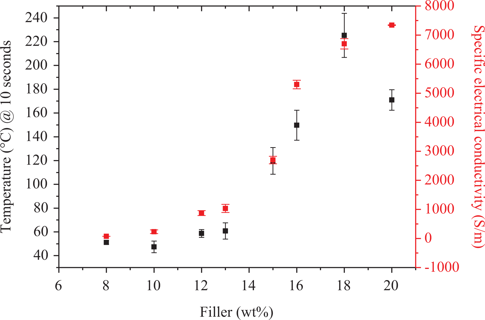
Filler versus conductivity and time of NiCCF/PP composites graph, electrical conductivity tested at room temperature, induction heating at 30 A and 456 kHz.
In Figure 5, hybrid filler (NiCCF/NiCGP/PP) concentrations versus electrical conductivity and induction temperature are plotted. A similar increase in the heating pattern as well as conductivity results were observed that were seen in fiber-filled sheets. Increasing the filler concentration, temperature and electrical conductivity were also increased. At lower concentrations, a low rise was observed; however, at electrical percolation, a sharp rise was also observed in induction heating.
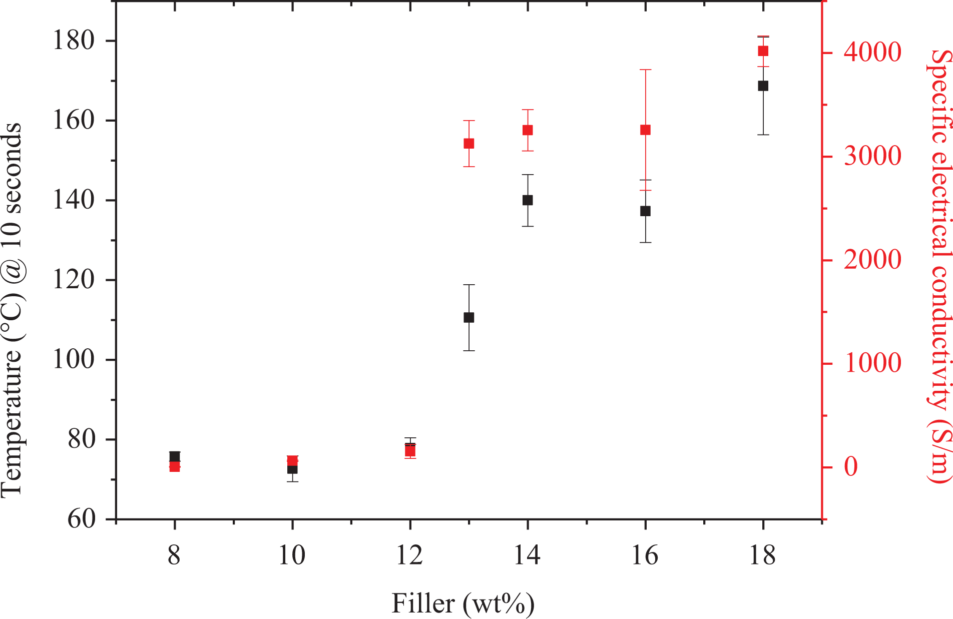
Filler versus conductivity and time of NiCCF/NiCGP/PP composites graph, electrical conductivity tested at room temperature, induction heating at 30 A and 456 kHz.
(b) Effect of frequency
Theoretically by increasing the frequency, the heating rates of conductive materials 47 also increase; however, it decreases due to many factors, for example, charged inductor impedance, losses in mountings, and other related negative factors. Frequency is a parameter that is related to the generator-capacitor system. In Figure 6, frequency dependence on induction heating at different filler concentrations of NiCCF/PP composites is evaluated from time–temperature graph. Temperatures were taken after first 10 s of experiment and the average temperature was calculated by different concentrations at various frequencies, and generator power was kept constant during testing.
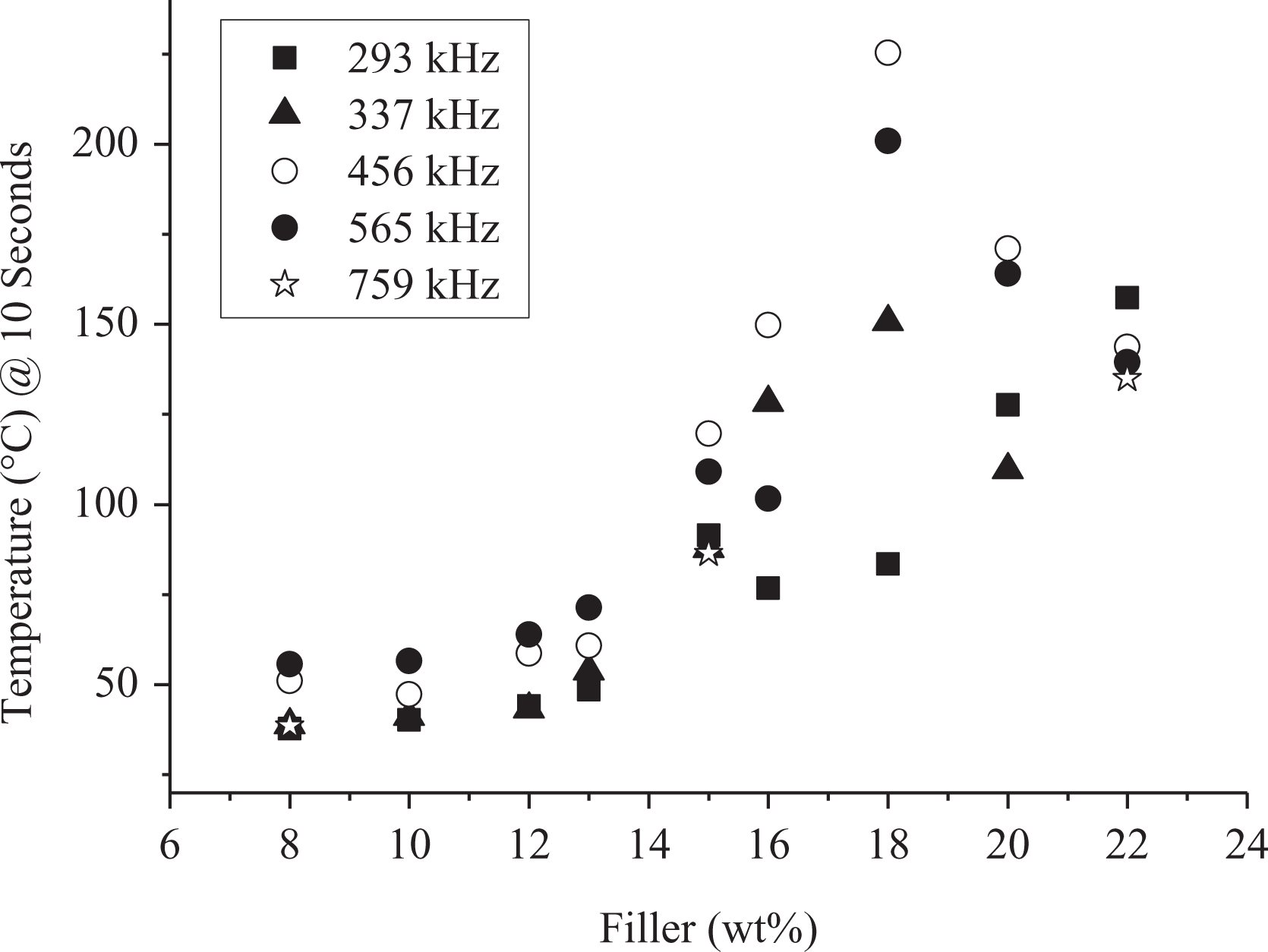
Effect of filler concentration versus frequency of induction heating of NiCCF/PP at 30 A (759 kHz at 15 A).
Increasing the frequency increased the heating effect and attained higher temperature during the 10-s testing interval. This was credited to high intrinsic electrical conductivity of NiCCF and finally the overall conductivity of the composite. Contrary to our observation, Rudolf et al. 48 noticed a quadratic reduction in time. At lower concentrations, increasing the frequency has higher effect on heating time. Heating time reduced up to 40%. At higher frequency near percolation, heating time further reduced; however, formation of straight burning lines was observed that may be due to restricted formation of eddy currents.
In Figure 7, hybrid filler sheets are tested at different frequencies. Average temperature was calculated during the first 10 s. At low frequency, heating temperature increases with increasing concentration. As it was observed in the conductivity results, percolation threshold observed around in hybrid filler was at 13–6%; similar results can be observed in low frequencies as well as higher frequencies. However, at higher frequencies, there was no distinct difference in temperature observed by changing the frequencies. At hybrid filler 8–6% and 13–6%, it can be seen that frequencies have a clear difference. As the concentration of particles was constant, the heating trend should be followed at lower concentrations with fibers. As the fibers concentration increases, the rise in temperature was observed at 337 kHz frequency; however, at other frequencies, this trend was not observed.
Effect of filler concentration versus frequency of induction heating of NiCCF/NiCGP/PP at 30 A.
(c) Effect of coupling distances
Distance between the sample and the coil is very critical, and by changing the distance, it can affect the heating. It is called coupling distance. Reduction in heating with increasing in coupling distance was expected due to lower magnetic field strength. Geometry of coil also important and the intensity of electromagnetic field depend on coil geometry. If the coupling distance i.e. distance between sample and coil, increases the intensity of electromagnetic field reduces. 48 Throughout the experimental process, the circular pancake coil was used in which the intensity of the electromagnetic field decreases with 1/s3. In Figure 8, the nickel coated short carbon fibers (NCSCF) reveals a very similar behavior at different concentrations. We selected two filler concentrations, one below and the other above the electrical conductivity threshold.
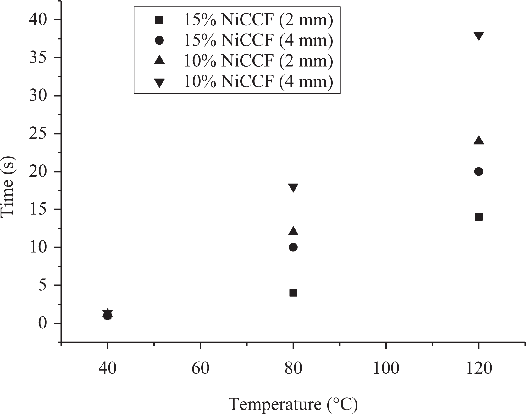
Effect of coupling distance on the heating time of different filler concentrations.
Penetration depth
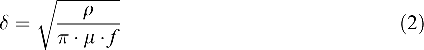
Increasing the frequency increases power and has better heating results; conversely, high frequencies reduce the penetration of electromagnetic field to certain depth, that is, skin depth. 48 Skin depth limits the heat generation to surface area at higher frequencies. The skin depth δ can be determined by the following equation (2), where ρ is electrical resistivity (Ω-m), µ is magnetic permeability (H/m), and f is frequency (Hz).
Relative magnetic permeability of nickel powder composites (67 vol.%) and nickel-coated graphite fibers composites (20 vol.%) has been reported 5.80 and 1.38, respectively, at 1 kHz. 49 The magnetic permeability values at 10 Hz to 100 kHz remained steady. Shu et al. 50 measured the susceptibility value as ratio of parallel to normal aligned fibers and got higher values in aligned fibers. The low penetration depth at high frequencies confines the heat energy to the surface regions of the part. In NiCCF/PP composites, the volume percent of fibers used was below 9 vol.%. Due to thin nickel coating, relative magnetic permeability may fall in the 1.03–1.05 range.
Morphological properties
(a) Micro-CT imaging
Both the sheets of NiCCF/PP and NiCCF/NiCGP/PP composite were processed using a twin-screw extruder and sheets were prepared through the Calendering process. Filled polymer melt aligned the fibers in flow direction. In micro-CT imaging in Figure 9(a), aligned fibers can be seen. The magnified cross-sectional view of the same can be seen in Figure 9(b), which shows the inside structure of fiber network. Due to some misaligned fibers, a good interconnecting network in plane as well as between different layers can be achieved. Therefore, a good heating effect can be obtained in such films. Head–tail connections may also serve as contact junctions, which adds to the heating further.
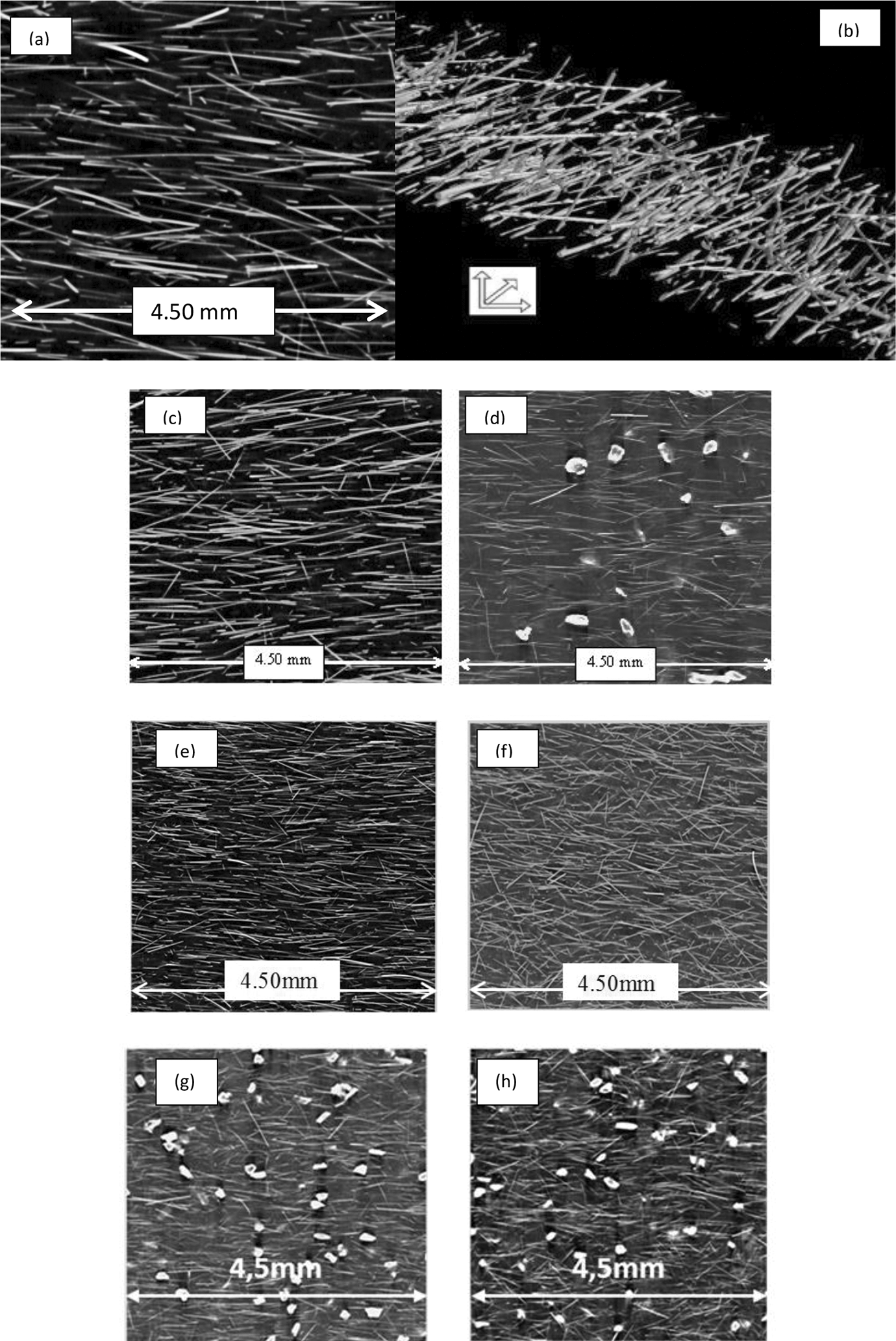
(a) NiCCF/PP (15–0), (b) cross-sectional view, (c) NiCCF/PP (13–0), (d) NiCCF/NiCGP/PP (13–6), (e) NiCCF/PP (15–0), before induction heating, (f) after induction heating, (g) NiCCF/NiCGP/PP (15–6), before induction heating and (h) after induction heating.
Figure 9(c) and (d) shows the micro-CT images of NiCCF/PP and NiCCF/NiCGP/PP composite samples, respectively. Good dispersion of fibers and particles can be seen. In the fiber/particle hybrid system, fibers seem to be not well aligned at few locations, as they were well aligned in sheets without particles. Only a few fibers were tilted to small angels at higher concentrations. In Figure 9(d), good dispersion of fibers and particles can be seen. In NiCGP/PP composites, ferromagnetic hysteresis heating was the single source of heat generation; therefore, a good dispersion of the particles in the matrix is required. Proper mixing and uniform dispersion of the particles were achieved due to adequate temperature shear compounding; however, possible oxidation of particles cannot be neglected.
In Figure 9(e) and (f), micro-CT images of NiCCF are taken before and after heating for comparison. When the polymer melts, it is difficult to observe the changes. Before induction heating, no misalignment of fibers could be observed. And after heating the samples, fibers got misaligned from the melting of the matrix polymer. When the polymer melts, the distance between the fibers reduces and the heating mechanism got changed. For instance, at the start of induction heating experiments, the dielectric heating was prominent; however, as the polymer melts, fiber–fiber distance reduces and the polymer layer thickness further reduces that shifts the heating mechanism in contact resistance heating mechanism. Therefore, micro-CT images taken after heating became important and explains that how fibers were spread over the sheet when melting takes place. Fibers were well distributed that showed the uniform heating and no hot spot formation observed.
In Figure 9(g) and (h), micro-CT images of NiCCF/NiCGP/PP are taken before and after heating for comparison. In the hybrid system, fibers were not well aligned as were in only fibers case. Therefore, to observe the melting of polymer is difficult. Before and after heating, misalignments could be observed; however, large misalignments can be seen. And after heating the samples, fibers as well as particles were accumulated due to melting. Therefore, the dispersion of particles was changed in the samples before and after heating. Therefore, heating mechanisms, that is, contact resistance and dielectric heating change due to the melting of the polymer. Fibers and particles distribution not much reasonably changes, which can be observed in IR thermal imaging. However, a large change was observed as the filler concentration increases.
In Figure 10, the orientation parameter is calculated from the images taken from the light microscopy analysis system attached with digital camera, and calculation was performed by software analysis of image taken. Bay and Tucker 51 have observed that weight average gives more accurate orientation results. In NiCCF orientation produced by the image analysis system, it is plotted against orientation angel and fiber content.
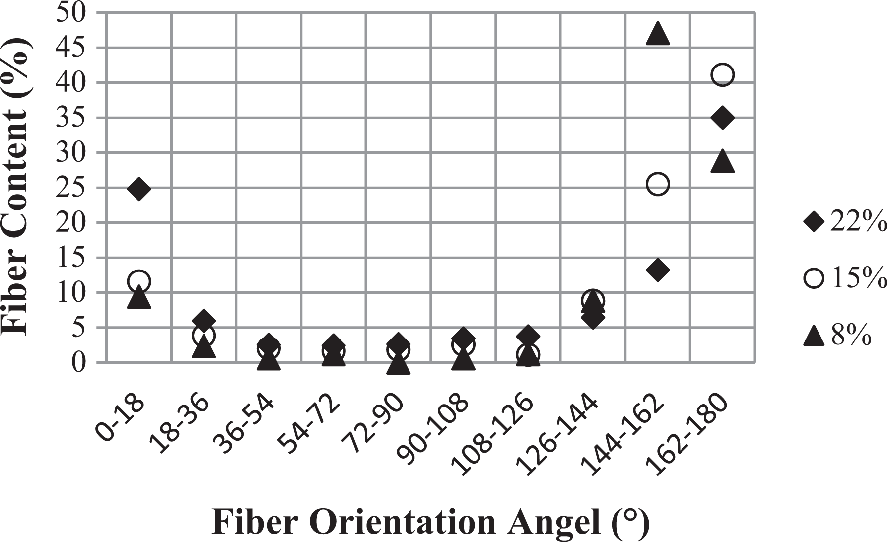
Fiber orientation angel versus fiber content of different NiCCF/PP composite thin sheets.
(b) IR thermal imaging
Temperature measurements and heating pattern imaging were performed by the IR thermal camera system. It’s being used for real-time measurements. The IR imaging system consists of a camera (Infratec), data processing software (IRBS), and a computer. IR thermal images were taken during induction heating experiments. Images taken by the IR thermal camera can also distinguish between the heating mechanisms, for example, magnetic hysteresis effect or eddy current losses. In coils, maximum field strength lies at center and reduces toward the outer area. Magnetic hysteresis effect shows heating circle at the center due to high electromagnetic field strength.
In Joule losses, eddy current travels in outer regions or away from the center; therefore, the heating pattern looks different from magnetic hysteresis. The heating pattern in Joule losses shows heating big circle at the outer region and empty from center due to induced currents. Figure 11(a) is a NiCCF/PP sample image, having 13% filler concentration of fibers. Image shows the heating pattern is similar to magnetic hysteresis effect; however, the diameter of the heating pattern is larger than the normal magnetic hysteresis effect that confirms the eddy current heating mechanism is also present. Dominant effect may be the magnetic hysteresis effect. Due to th enickel coating of fibers, magnetic hysteresis effect is dominant; however, the shape is oval, and that may be the reason of being aligned and conductive fibers network. Figure 11(b) shows NiCGP/PP samples image with 15% filler concentration of particles. The heating pattern tells that magnetic hysteresis effect is the only heating mechanism present. It is pertinent to mention here that in Figure 11(a) and (b), the sample size is not the same. In Figure 11(a), it is 120 × 120 mm, and in Figure 11(b), it is 60 × 60 mm. Therefore, the heating pattern is the combination of all the heating mechanisms. In fibers case (Figure 11(a)), heating shows the magnetic hysteresis effect along with eddy current effect. Therefore, the big red circle with a large diameter was observed during heating. However, with particles (Figure 11(b)), this is not the case.
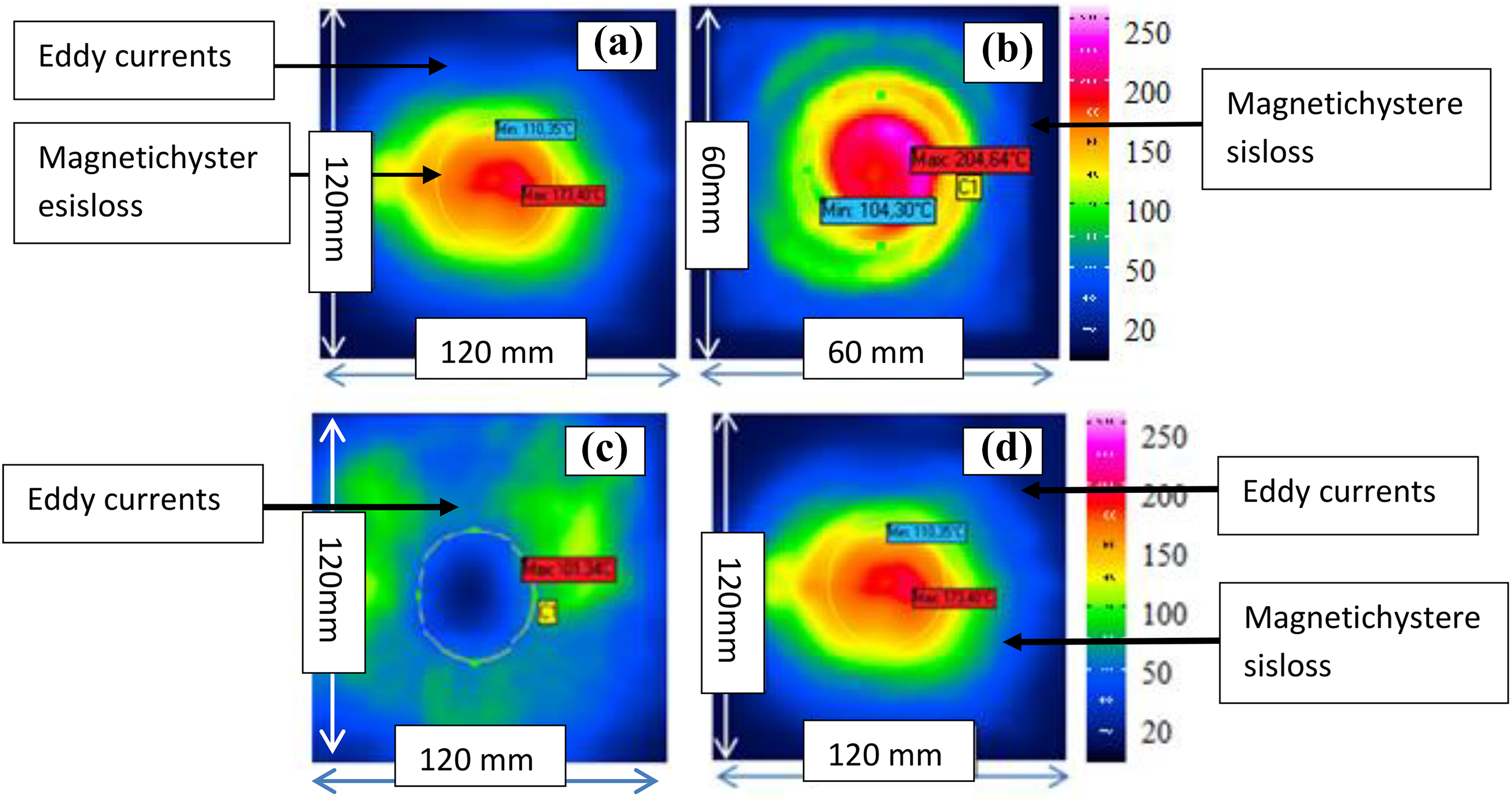
(a) NiCCF/PP (13–0)%, (b) NiCGP/PP (0–15)%, (c) 20% SCF/PPS, (d) NiCCF/PP (13–0)%.
To distinguish between the heating patterns, that is, magnetic hysteresis effect and eddy current, fibers without nickel coating were used. Due to the absence of metallic coating, magnetic hysteresis effect will not be present. Figure 11(c) is a short carbon fiber filled polyphenylene sulfide sample image, with 20% filler concentration.
It is very clear from the image that eddy currents travel in the outer region; therefore, heating was present in the outer region due to Joule losses. However, the center of the coil shows no heating. The image shows the heating pattern of eddy current losses. In this case, the sample size was 120 × 120 mm so that heating area can be compared. In Figure 11(d), nickel-coated fibers show the combined effect of eddy currents and magnetic hysteresis; however, magnetic hysteresis shows bright effect.
In Figure 12(a) and (b), NiCCF/NiCGP/PP samples are compared with NiCGP/PP. In Figure 12(a), NiCCF/NiCGP/PP shows the combined effect of eddy currents and magnetic hysteresis. Sample size was also 120 × 120 mm. The heating pattern was similar like in fibers; however, the shape of the red heating circle was perfect round. In Figure 12(b), NiCGP/PP only magnetic hysteresis effect is present. Sample size was 60 × 60 mm, therefore, it shows that magnetic hysteresis effect remains smaller as compared with hybrid filler.
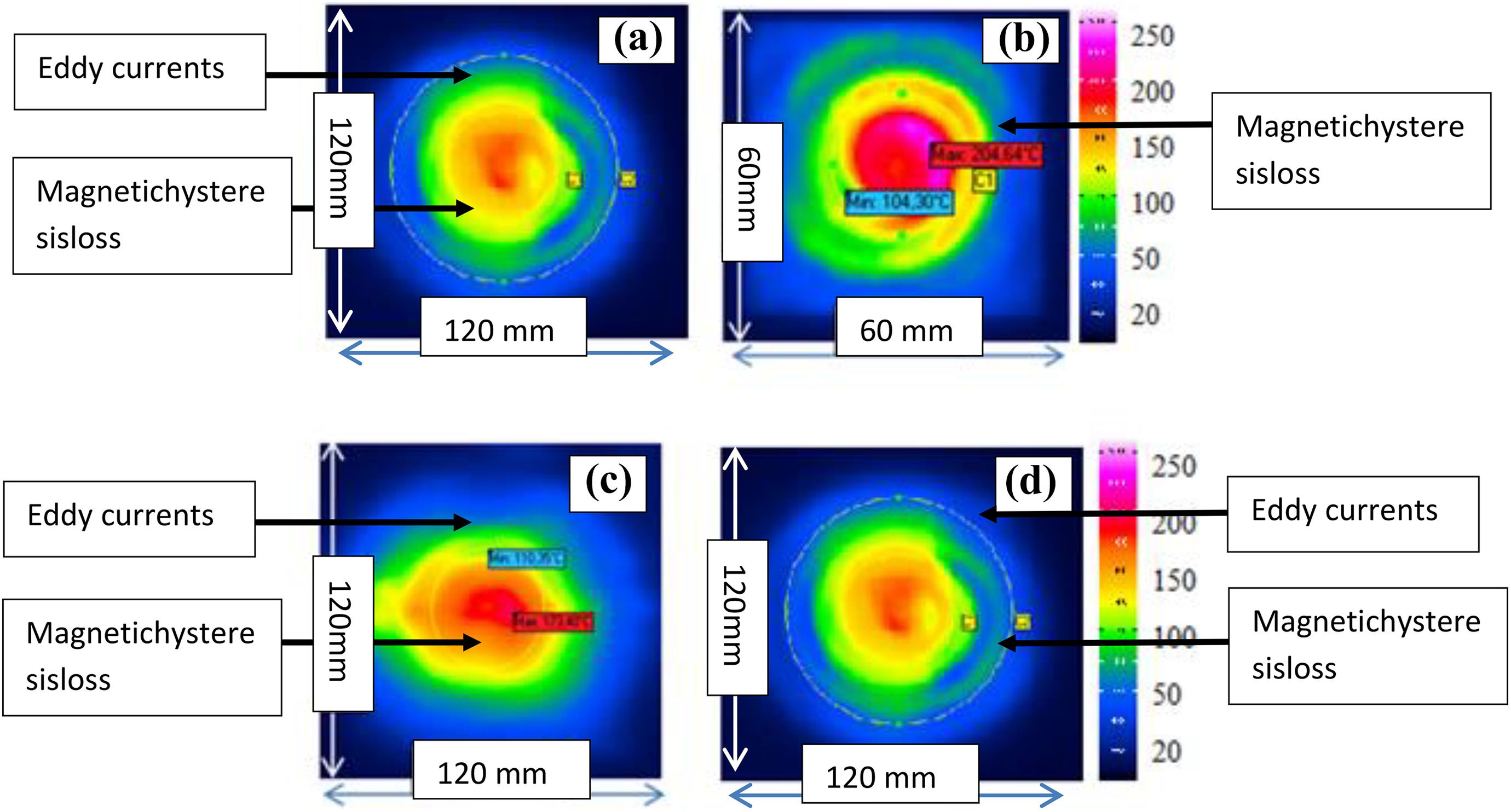
(a) NiCCF/NiCGP/PP (13–6)%, (b) NiCGP/PP (0–15)%, (c) NiCCF/PP (13–0)%, and (d) NiCCF/NiCGP/PP (13–6)%.
In Figure 12(c) and (d), NiCCF/PP and NiCCF/NiCGP/PP samples are compared. Figure 12(c) and (d) shows the combined effect of eddy currents and magnetic hysteresis. Both these samples have a dimension of 120 × 120 mm. In both the cases, the heating effect of magnetic hysteresis is dominant; however in Figure 12(d), hysteresis effect is more prominent than in Figure 12(c). This may be due to two reasons. First one is that the addition of particles increases the nickel concentration that highlighted it and second is due to reduced electrical conductivity. It can also be seen that the saturation magnetization of hybrid-filled system is higher than only fibers. If they are compared with only particle-filled samples, the heating circle was much bigger than particle-filled samples. The change in heating circle diameter confirms that eddy current and magnetic hysteresis effect were both present.
Conclusion
The susceptor was developed using NiCCFs, NiCGP, and a combination of both. Mixing of the said fillers was achieved by melting blending in extruder and sheets were prepared by the Calendering machine. It was observed that electrical conductivity was higher in NiCCF/PP sheets; however, hybrid sheet was lower in conductivity. Induction heating rate at low frequency was lower at low filler concentration in NiCCF/PP; however, at higher filler concentration, it was high. A similar trend was also observed at high frequency induction heating experiments in NiCCF/PP and hybrid filler system. The main reason behind the higher heating rate in hybrid filler at low concentration may be due to the higher nickel concentration; however, at higher concentration, electrical percolation dominated the heating rate. At higher filler concentration in NiCCF/PP, the heating rate was dominant due to Joule losses; however, magnetic hysteresis loss was also present.