
Abstract
The fiber-reinforced polymer composites are important alternative for conventional structural materials because of their excellent comprehensive performance and weight reduction. The mechanical properties of such composite materials are mainly determined by the fiber orientation induced through practical manufacturing process. In the study, a through process modeling (TPM) method coupling the microstructure evolution and the mechanical properties of fiber-reinforced composites in practical processing is presented. The numerical methodology based on the finite volume method is performed to investigate three-dimensional forming process in the injection molding of fiber-reinforced composites. The evolution of fiber orientation distribution is successfully predicted by using a reduced strain closure model. The corresponding finite volume model for TPM is detailedly derived and the pressure implicit with splitting of operators (PISO) algorithm is employed to improve computational stability. The flow-induced multilayer structure is successfully predicted according to essential flow characteristics and the fiber orientation distribution. The mechanical properties of such anisotropy composites is further calculated based on the stiffness analysis and the Tandon–Weng model. The improvement of mechanical properties in each direction of the injection molded product are evaluated by using the established mathematical model and numerical algorithm. The influences of the geometric structure of injection mold cavity, the fiber volume fractions, and the fiber aspect ratios on the mechanical properties of composite products are further discussed. The mathematical model and numerical method proposed in the study can be successfully adopted to investigate the structural response of composites in practical manufacturing process that will be helpful for optimum processing design.
Introduction
The fiber-reinforced polymer composites have recently become important alternative for conventional structural materials in the aerospace, automotive, and ordnance industries because of their excellent comprehensive performance and weight reduction. If thermoplastics are utilized as matrix material, the properties of such composites depend strongly on the fiber orientation developed in practical forming process, besides the fiber volume fraction, the fiber aspect ratio and the interfacial adhesion between the fibers and matrix. 1
In recent years, many researchers have dedicated to investigate the mechanical response of fiber-reinforced composites through experimental method. Mazahir et al. 2,3 experimentally measured fiber orientation along three different heights representative of shell, transition, and core layers, in order to understand the evolution of orientation along the radial direction in the frontal region in injection molding process of a center-gated disk. Thia et al. 4 explored the application of X-ray computed tomography imaging technique for observing and measuring fiber application in two injection-molded specimens with and without a weldline. Ayadi et al. 5 combined X-ray microtomography and finite element computation to determine the elastic modulus in various positions in an open hole plate configuration with dissymmetric fiber distribution. Melenka et al. 6 experimentally evaluated the elastic properties of the fiber-reinforced 3-D printed structures and predicted elastic properties using an average stiffness method. A predictive model was also proposed for designers to evaluate the elastic properties of fiber-reinforced 3-D printed parts to be used for functional components which require specific mechanical properties. Mortazavian and Fatemi 7,8 experimentally investigated anisotropy effects on tensile properties of two short glass fiber-reinforced thermoplastics, and the variation of tensile toughness with fiber orientation and strain rate was evaluated. The micromechanisms of fatigue failure at different temperatures were also investigated and a fatigue life estimation model was presented which correlates data for different temperatures, fiber orientations, and stress ratios. Due to time consuming and costly testing of the experimental measurement, many researchers tried to use theoretical modeling and numerical method to investigate the effect of microstructure on the mechanical properties of polymer composites. Dean et al. 9 developed a fully-coupled thermomechanical invariant-based elastoplastic constitutive model for short fiber-reinforced composites. Sencu et al. 10 proposed a fiber tracking algorithm to efficiently locate fiber centerlines from X-ray computed tomography images of carbon fiber-reinforced polymer, which was also used to generate microscale finite element model. Brighenti et al. 11 developed a micromechanical model for unidirectional or random fiber-reinforced materials under cyclic loading. Modniks 12,13 evaluated the mechanical properties of short fiber-reinforced composites by orientation averaging of the unit cell properties obtained by finite element method. Yang et al. 14 presented dynamic simulation of fiber-reinforced composite materials in mold filling process with double inlets based on the gas–solid–liquid model, and the mechanical properties were further calculated with different slenderness ratios and fiber volume fractions. Wang et al. 15 proposed a finite element model to examine the effects of the fiber content and fiber length on Young’s modulus of short fiber-reinforced polypropylene foams based on periodic tetrakaidecahedrons. Cosmi 16 adopted both morphological and numerical methods to capture the principal direction of anisotropy and the differences between shell and core among the volumes of interest within each region in short glass fiber-reinforced polymer parts obtained by injection molding. Beicha et al. 17 considered two microstructures including hexagonal periodic and random arrangement of fibers and studied the influence of microstructure on effective transverse elastic behavior of fiber-reinforced composites by finite element simulation.
From an industrial viewpoint, rigorous model that considers the effects of practical processing conditions on fiber orientation is the basis for correct prediction of the mechanical properties of fiber-reinforced polymer composites. In the present study, a novel through process modeling (TPM) method is adopted for the prediction of mechanical properties of short fiber-reinforced polymer composites produced by injection molding based on finite volume simulation. By using the TPM method, the microstructure evolution in practical processing and the properties of composites product are coupled with each other. The structural response of composites in practical manufacturing process can hence be exactly evaluated and the optimum processing parameters can be further chosen at the stage of processing design based on the properties evaluation of composites product. The mathematical model of 3-D fiber suspension flow is established with a reduced strain closure (RSC) model for the numerical prediction of microstructure developed during the mold filling process. The corresponding finite volume model is derived and the details of numerical schemes are introduced. Stable solving method for the nonlinear problem is investigated and the pressure implicit with splitting of operators (PISO) algorithm is employed to improve computational stability. The essential flow characteristics and fiber orientation are investigated based on the established mathematical model and numerical algorithm. The Tandon–Weng model is adopted to compute the mechanical properties of unidirectionally aligned composites including Young’s modulus, shear modulus, and Poisson’s ratio. According to the numerical results of fiber orientation, the mechanical properties of injection-molded anisotropy polymer composites that are regarded as laminated orthogonal structure are predicted using stiffness analysis. The influences of mold cavity structure and fiber characteristics on the mechanical properties of fiber-reinforced polymer composites are further illustrated based on the proposed modeling and simulation method.
Mathematical modeling
Fiber suspension flow
Injection molding and extrusion are main forming processes utilized for the producing of fiber-reinforced polymer composites parts. In practical mold filling process of polymer matrix with fiber inclusion, the flow field can be seemed as non-compressible non-Newtonian fiber suspension flow. Based on the conservation of mass, momentum, and energy, the governing equations to solve fiber suspension flow problem can be obtained from the continuity equation (1), the momentum equation (2), and the energy equation (3) as follows


where
In order to trace the fiber suspension–air interface in the flow front region, the volume of fluid method is adopted, where the fraction of volume of the fiber suspension in each cell is represented by a function of volume fraction φ as follows
where
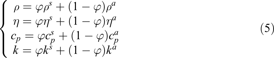
The physical properties including density ρ, viscosity η, specific heat capacity cp, and thermal conductivity k in each cell can be calculated by averaging the properties of fiber suspension and air as follows
In the fiber suspension flow, the orientation of fibers can be represented by a probability distribution function of fiber orientation vector


where
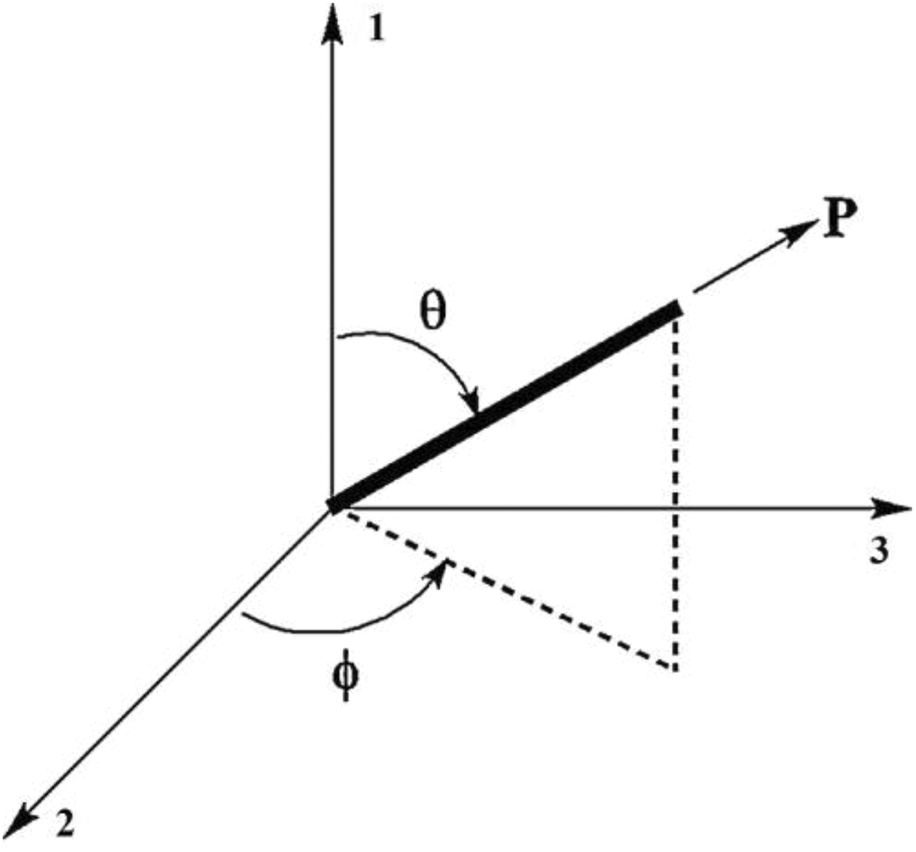
Definition of fiber orientation vector.
Accurate calculation of the fiber orientation state can be solved through equations (6) and (7), which requires huge computational resources. The second-order orientation tensor

After the second-order and the fourth-order orientation tensors are introduced into equations (6) and (7), the following evolution equation of the second-order orientation tensor can be derived

Because of too rapid evolution of orientation in transient shear flow of the above equation that is derived based on Folgar and Tucker model, some modifications were proposed to slow down the orientation kinetics. In the study, a RSC model is adopted to delay the orientation evolution based on an assumption that the effective velocity gradient experienced by the group of fibers is less than the bulk velocity gradient due to the cluster of fibers 20


where κ is the strain reduction factor,
In order to calculate the second-order orientation tensor
The fiber orientation in the fluid matrix can be coupled with the momentum via constitutive relation. In the fiber suspension flow system, the composite stress can be presumed to be the linear sum of stress contributions from the non-Newtonian fluid

The non-Newtonian fluid contribution

where ηn is the non-Newtonian viscosity.
The fiber anisotropy and the effect of fiber orientation on suspension rheology is taken into account in the stress tensor as follows 21

where N
Estimation of mechanical properties
In order to calculate the mechanical properties of fiber-reinforced polymer composited with laminated structure, the properties of unidirectional fiber-reinforced materials are firstly estimated in the study. These unidirectional properties can then be averaged across laminated structure developed in practical forming process according to the fiber orientation distribution predicted through above numerical investigation of fiber suspension flow.
The mechanical property parameters of unidirectionally aligned composites including longitudinal Young’s modulus Y11, transverse Young’s modulus Y22, in-plate shear modulus S12, out-plate shear modulus S23, and major Poisson’s ratio v12 are firstly calculated according to Tandon–Weng model as follows 22


where Yp, Sp, and vp denote the Young’s modulus, shear modulus, and Poisson’s ratio of the polymer matrix, Yf, Sf, and vf denote the Young’s modulus, shear modulus, and Poisson’s ratio of the fiber inclusion, α is the fiber volume fraction, Eijkl are the following components of Eshelby’s tensor


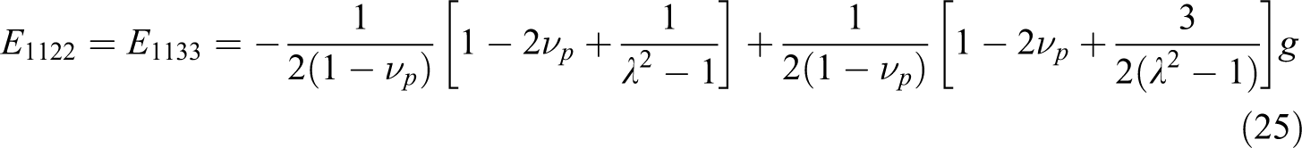


where
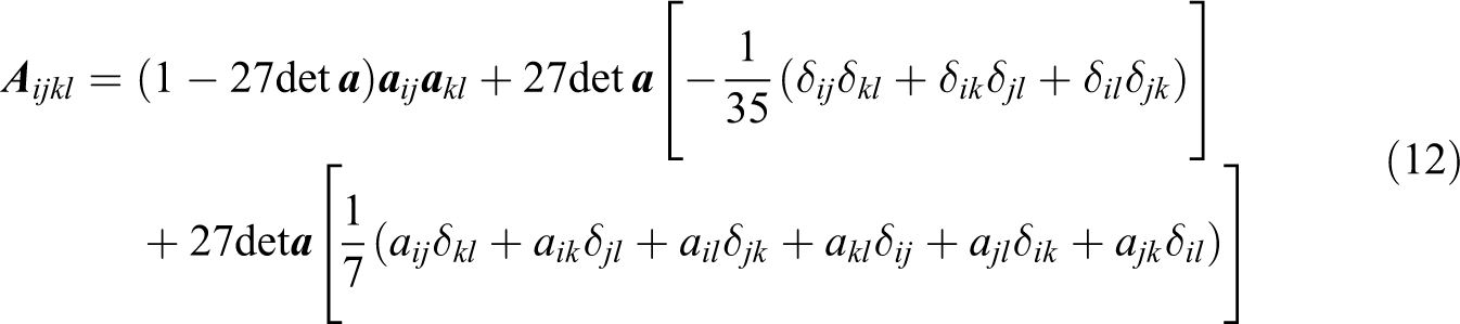
The following explicit function of the Eshelby’s tensor can hence be obtained


where


where
The components of stiffness coefficients matrix Cij can then be calculated according to the mechanical property parameters of the unidirectional composites as follows


where
In order to predict the mechanical properties of non-unidirectional oriented short fiber-reinforced polymer composites, the off-axis matrix of stiffness coefficients Cij have to be converted to the ortho-axis matrices of stiffness coefficients
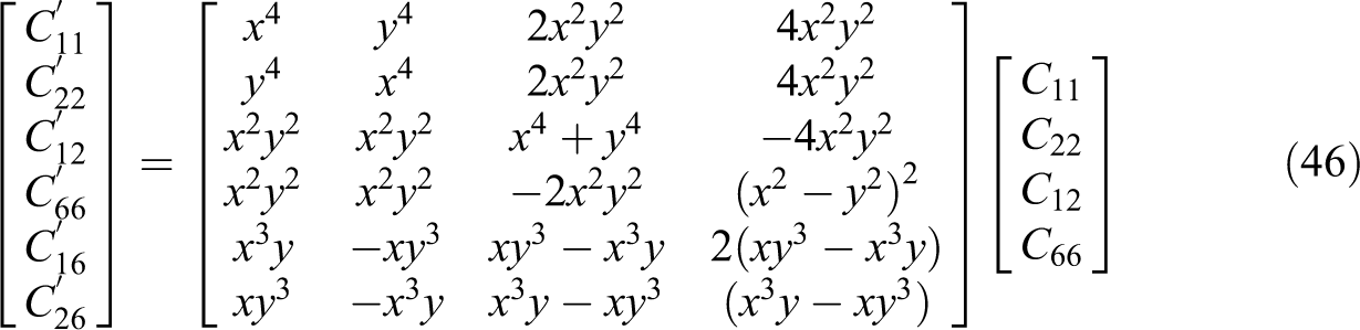
where
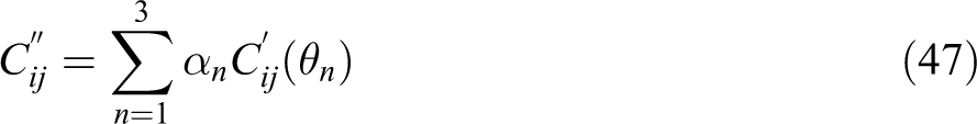
where α denotes three eigenvalue of the orientation tensor.
According to the multilayer structure developed in practical forming process that will be detailedly discussed in the “Results and discussion” section, the total stiffness matrix
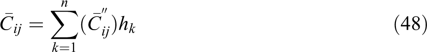
where k is the number of different layers and h denotes characteristic thickness of each layer.
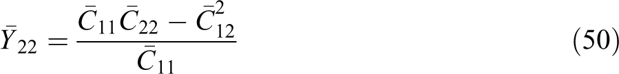
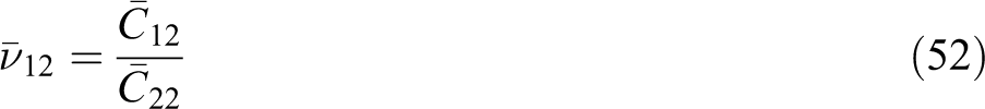
The mechanical properties of fiber-reinforced composite products including longitudinal Young’s modulus, transverse Young’s modulus, shear modulus, and Poisson’s ratio can hence be obtained through the total stiffness matrix as follows


Numerical algorithm
The nonlinear system of governing equations consisting of the continuity equation (1), the momentum equation (2), the energy equation (3), the interface tracking equation (4), the fiber orientation equation (10), and the constitutive equation (13) form a closed set of equations in terms of the
The governing equations for fiber suspension flow can be written as the following general transport equation

where φ is tensor-valued property of the flow, Θ and Γ are constant coefficients.
After integrated within the control volume and time domain, the following equation can be obtained
According to Gauss divergence theorem, the body integral in spatial domain can be converted into the area integral as follows


where φf is the variable value in the center of each surface on the control volume.
Based on the collocated grid system, the following semi-discrete governing equation can be obtained
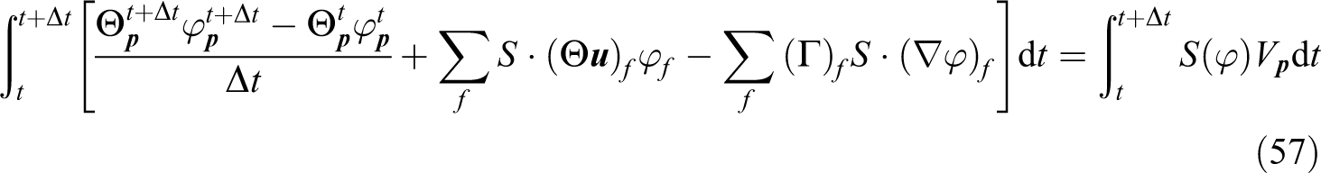
After time discretization, the discrete form of governing equations can be obtained as follows
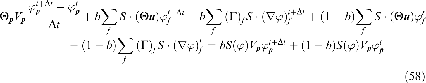
When different coefficient value b (b = 1, b = 0, and b = 1/2) is adopted in equation (58), different difference schemes including the implicit difference scheme, the explicit difference scheme, and the Crank–Nicolson difference scheme can be obtained.
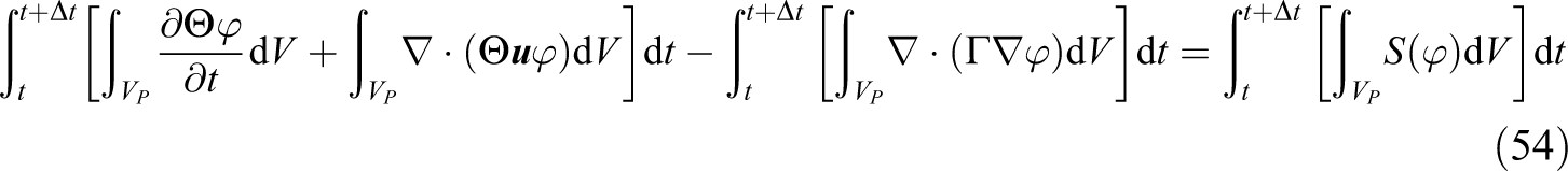
After spatial and time discretization, the governing equations in each control volume can be written as the following algebraic equation

The global matrix equation of the governing equations for all the control volume within the calculation domain can then be assembled as

where
The ICCG and Bi-CGSTAB iterative solution methods are adopted in the calculation of above large nonlinear matrix equation. 23,24 In order to avoid computational divergence, the relaxation factor υ is introduced in the discretized governing equation (60) at each time step and the following iterative equation can be obtained

In each time step, the convergence criteria is defined upon the requirements on velocity, pressure, temperature, and orientation. When the relative error of each variable is less than a set value, convergence is considered to be achieved. Based on the converged fundamental solution, the strain rate tensor and extra stress tensor can be derived.
In order to avoid oscillations in pressure solution, the PISO algorithm which includes an estimation step and two correction steps for pressure field and velocity field is adopted in the study. 25,26
According to the discrete form of momentum equation, the following semi-discrete equation can be written as

If substituting the initial pressure field p* of current time step into the equation (62), the velocity field
After substituting the corrected velocity field

The first corrected velocity field
The above correction step is repeated again and the second velocity correction term
After introducing the corrected velocity field

The second corrected velocity field
Results and discussion
Process modeling
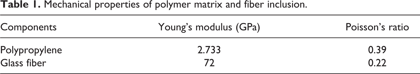
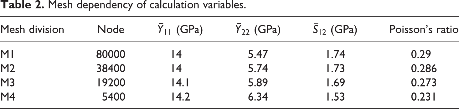
In the study, the mechanical property of an injection-molded flat plate formed with glass fiber-reinforced polypropylene is investigated based on the proposed mathematical model and numerical method. The injection mold cavity of flat plate is shown in Figure 2, where the length L is 0.06 m, the width W is 0.03 m, and the thickness H is 0.003 m. The mechanical properties of both polymer matrix and fiber inclusion of the studied composites are shown in Table 1. 27 The average aspect ratio of the glass fibers suspended in the polypropylene matrix is 25, and 30% by volume short glass fibers were used as reinforcement. The flat plate is formed by injecting fiber suspension flow inside the mold cavity with a volume flow rate of 50 cm3/s, where the temperature of polymer melts and that on mold wall is 498 K and 311 K, respectively. In order to learn about the effects of mesh refinements on the numerical results and the convergence of the numerical scheme, calculation based on four mesh division schemes M1, M2, M3, and M4 are firstly carried out as shown in Table 2. By comparison, almost the same predictions of longitudinal Young’s modulus, transverse Young’s modulus, shear modulus, and Poisson’s ratio are found for the more refined mesh division schemes M1 and M2. Considering sufficient accuracy and computational cost-effectiveness, we accept mesh division M2, shown in Figure 2, as our base mesh and all the results to be given below are computed with the mesh division M2 unless otherwise stated.
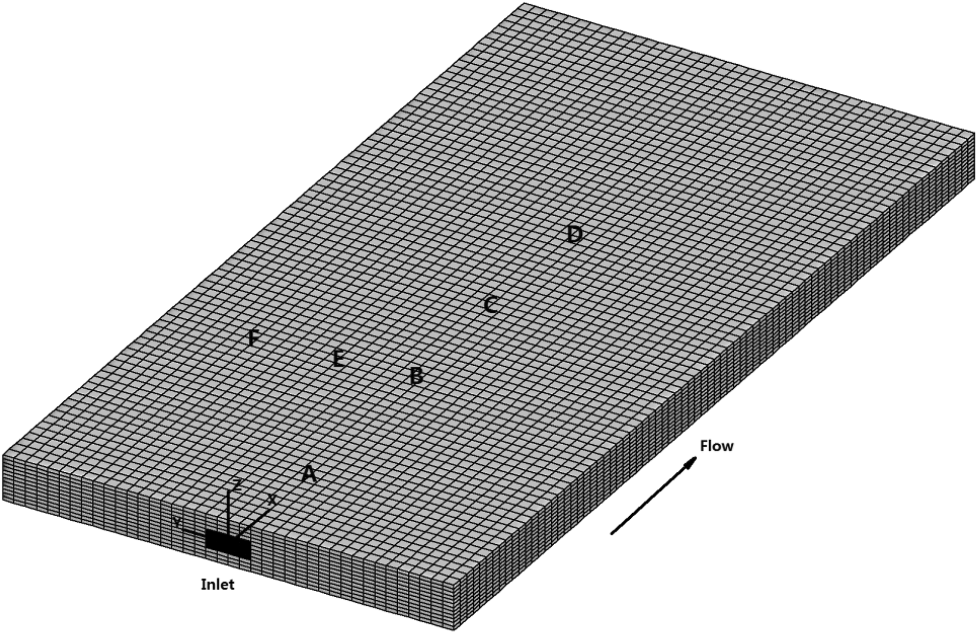
Geometric model of the injection mold cavity.
Mechanical properties of polymer matrix and fiber inclusion.
Mesh dependency of calculation variables.
Distribution of fiber orientation
According to distribution of fiber orientation, a multilayer structure across thickness of the composite products including two skin regions, two shell regions, two transition regions, and a core region have been found in many experimental researches as shown in Figure 3. 4,16 The skin regions can be found in the case of slow injection speed because of the fountain flow characteristics, while they may disappear in the case of fast injection speed. 5 The fibers in the shell regions are mainly aligned along the flow direction due to high shearing near the mold wall. Owing to lower shearing and high extensional flow effects in the core region, the fibers are more aligned transversely to the flow direction. Two transition regions are located between the shell regions and the core region, where non-preferential orientation can be found.
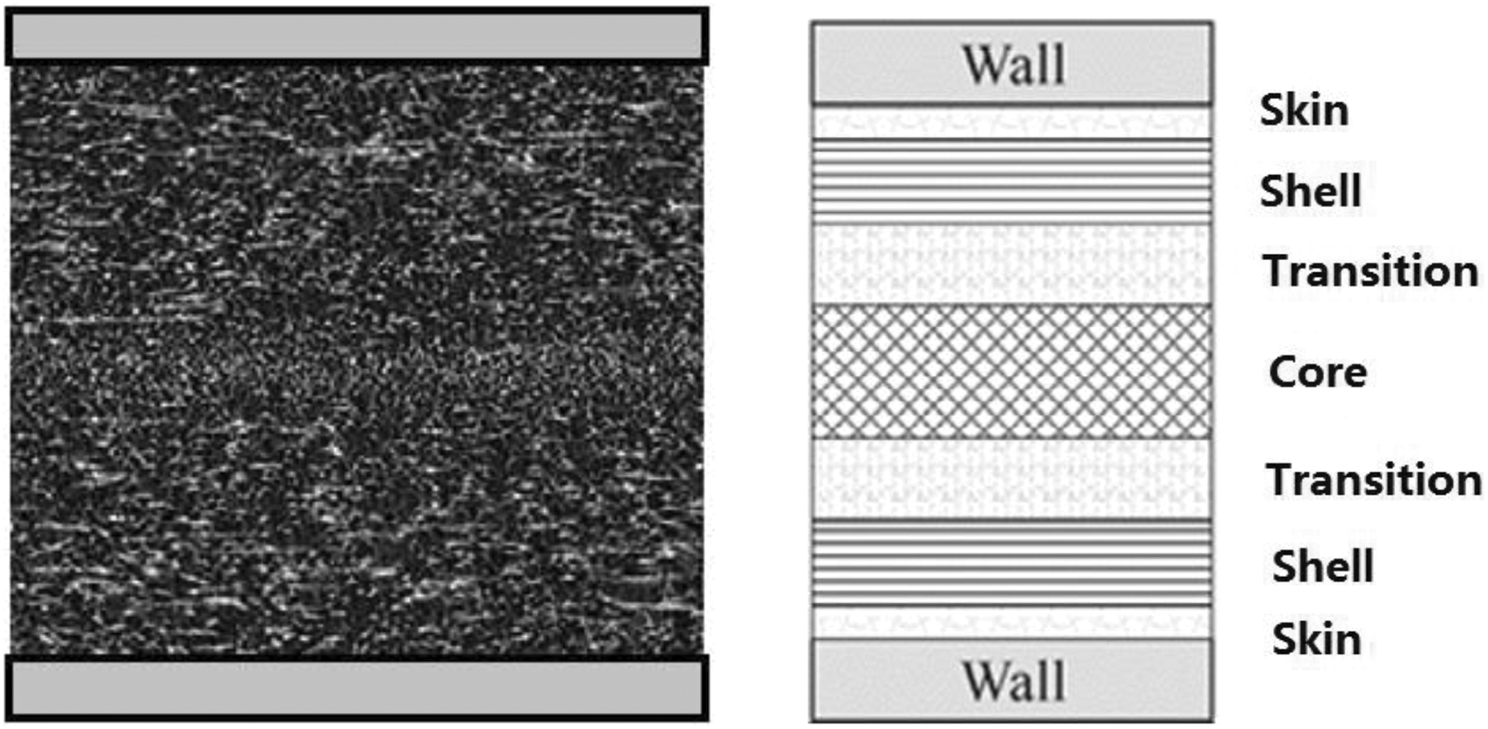
Multilayer structure of the fiber-reinforced composites.
By using the proposed mathematical model and numerical method, the evolutionary process of fiber orientation within 3-D flat plate injection mold cavity can be comprehensively predicted. Stable calculation is achieved as shown in Figure 4. The tolerance iteration of fiber orientation tensor components are found to be smoothing for the case of injection mold filling flow. Figure 5 shows comparison of fiber orientation evolution within the mold cavity at different time point. It can be found that the fibers are mostly aligned along transverse direction near the injection gate and gradually aligned along flow direction after entering the main flow channel. Because of the structure variation from the injection gate to the main flow channel, the flow field can be divided into three regions including entry, lubrication, and front. The fiber orientation behavior within the injection gate directly influences its evolution within the main flow channel. Owing to the expansion flow characteristics near the injection gate, extensional deformation is dominated in the entry region. According to the distribution of fiber orientation tensor components axx and ayy, fibers tend to align along the direction of extension, especially around the centerline of flow channel. As the suspension flow filling into the mold cavity, the lubrication region is formed where a combination of shear and extensional deformation is present. Fibers tend to align along flow direction near the mold wall where the shear effect is found to be dominated, and they tend to align transversely to the flow direction around the centerline where the extension effect dominates.
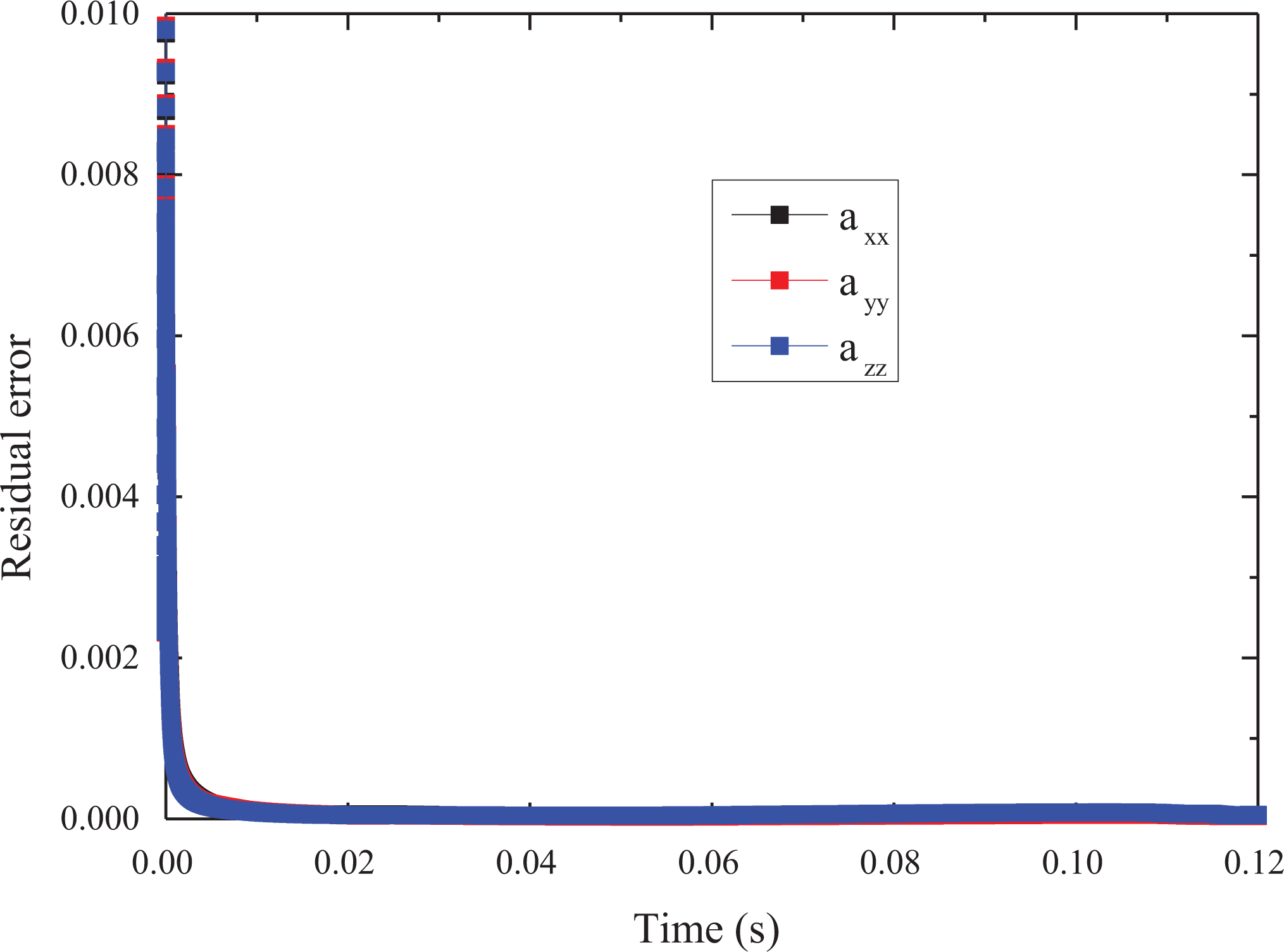
Evolution of calculation residual error.
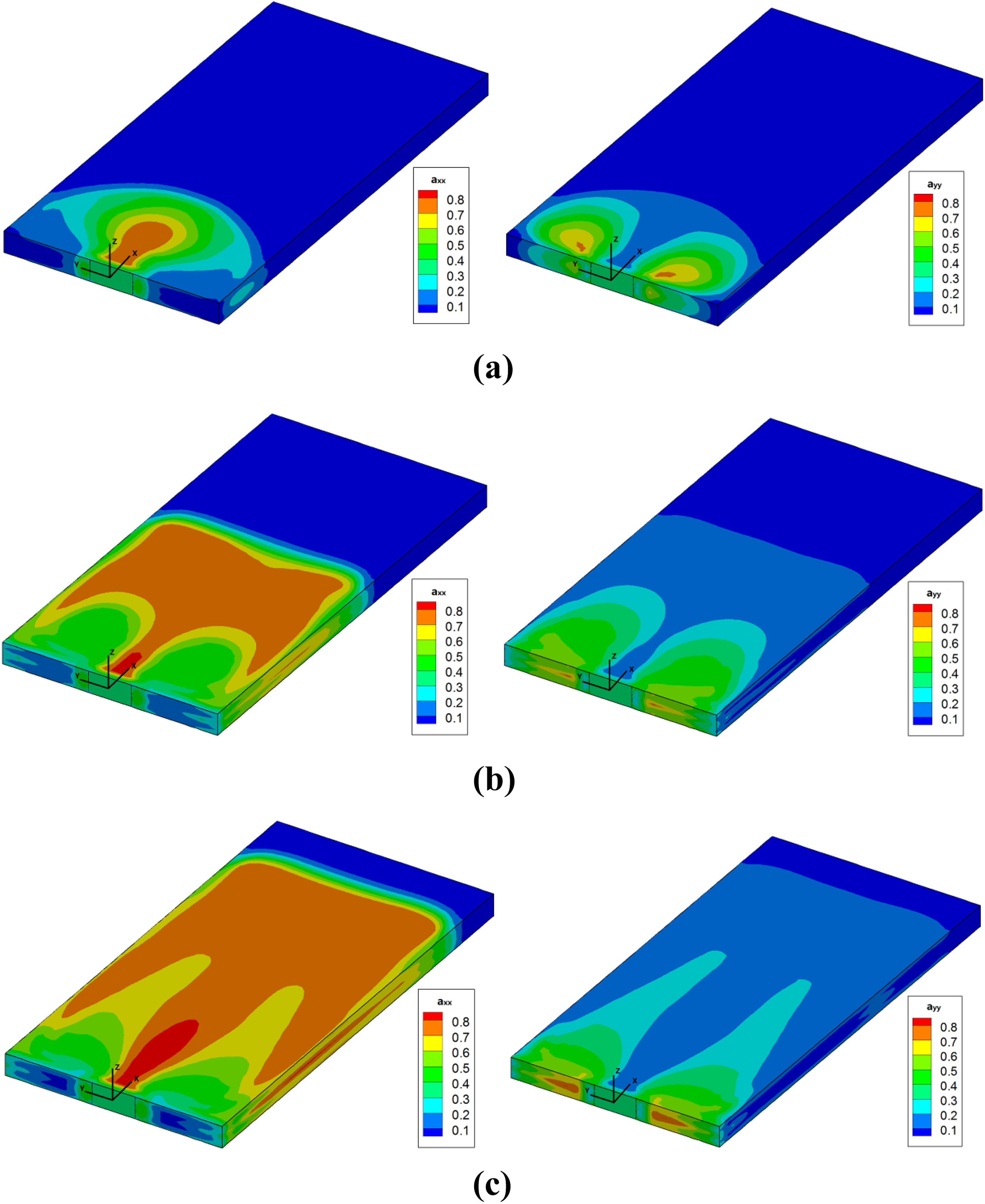
Evolution of fiber orientation during injection molding process: (a) 0.02 s; (b) 0.06 s; (c) 1.0 s.
Owing to effects of shear and extension flow behavior on fiber orientation during mold filling process, a multilayer structure across the thickness within the flow channel has been observed. The distribution of fiber orientation on different positions A (0.005 m,0), B (0.02 m,0), C (0.03 m,0), D (0.04 m, 0), E (0.02 m, 0.005 m), and F (0.02 m, 0.01 m) as shown in Figure 2 after filling into the mold cavity is extracted in the study to quantitatively evaluate such distinct structure as shown in Figure 6. Figure 6(a) to (f) shows the distribution of orientation tensor components axx, ayy, and azz across the thickness on different positions A, B, C, D, E, and F, respectively. The values of orientation tensor components axx are found to be larger than 0.5 in the shell region, especially in the downstream flow channel where longer shearing effects are experienced. In the core region where extension flow dominates, the values of orientation tensor components ayy are found to keep increasing. Between the shell region and the core region, a transition region is found where the value of orientation tensor components axx, ayy, and azz are close to each other. A non-preferential orientation is found to occur in the upstream flow channel approaching to the injection gate where much more extension effect may exist for the structure variation from the injection gate to the main flow channel. By comparing the variation of fiber orientation on positions A, B, C, and D along the flow direction, we can find that the orientation degree is continuously enhanced along flow direction as the fiber suspension flow fills into the mold cavity for the reason of continuous shearing effect. Larger variations are also found through the comparison of fiber orientation on positions B, E, and F along the transverse direction. Fibers are found to be aligned to the flow direction obviously near the mold wall, while non-preferential orientation are found along centerline within the mold cavity especially near the entry region.
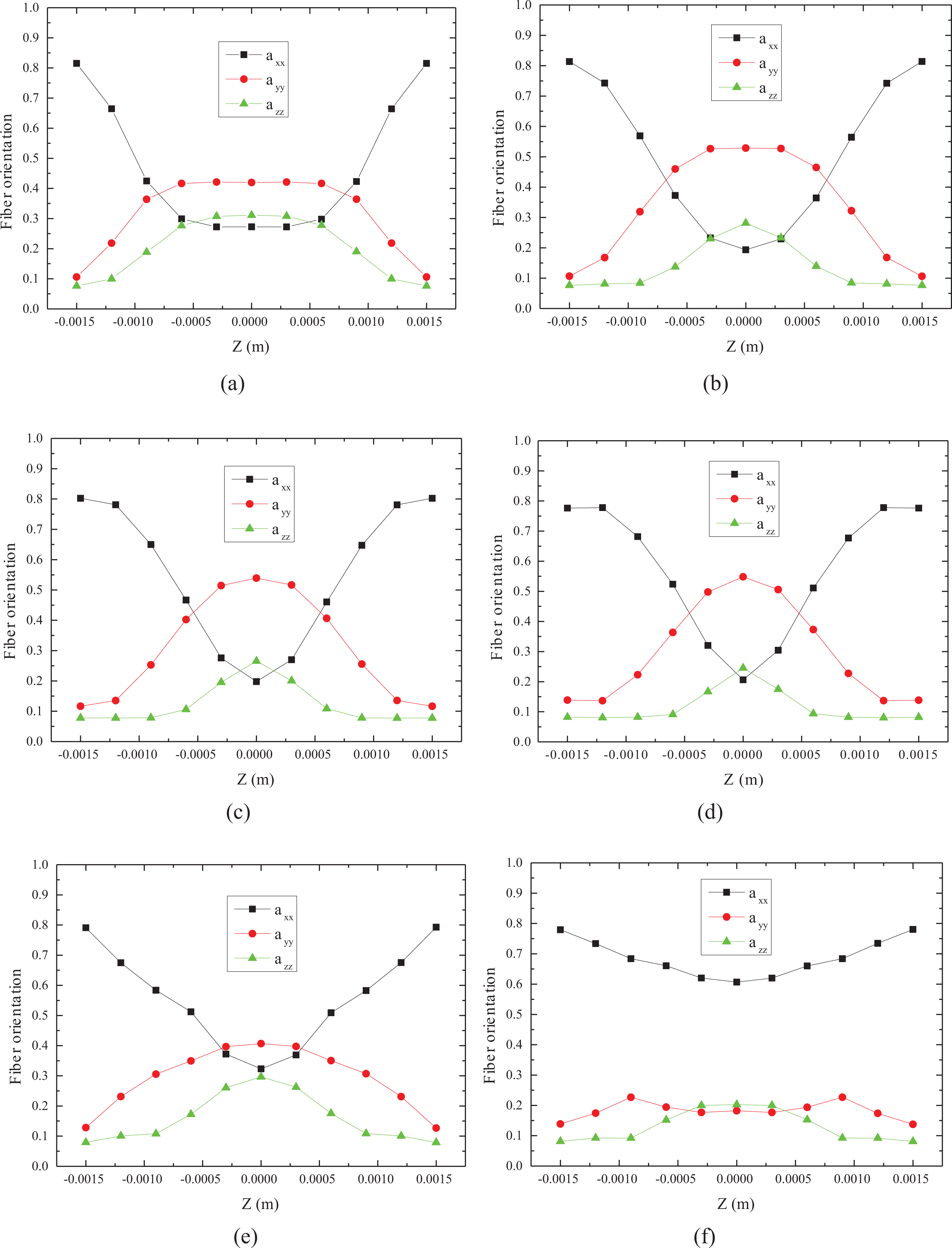
Comparison of fiber orientation distribution within the injection mold cavity: (a) position A; (b) position B; (c) position C; (d) position D; (e) position E; (f) position F.
Prediction of mechanical property
The orientation of fibers within the polymer matrix can directly influence the mechanical properties of fiber-reinforced composites. Based on the fiber orientation predicted in the study, the mechanical properties of the injection-molded flat plate is investigated through TPM method and the influence factors on the mechanical properties are further discussed. According to the parameters of mechanical property predicted with the mesh division scheme M2 as shown in Table 2, we can find that the longitudinal Young’s modulus and transverse Young’s modulus are improved about 5.12 and 2.1 times, respectively. The value of longitudinal Young’s modulus is also found to be more than twice of the transverse Young’s modulus. That is to say the injection-molded fiber-reinforced flat plate shows obviously anisotropy. Under current processing conditions as illustrated in the “Process modeling” section, the influence of geometric structure of mold cavity on the mechanical property of the injection part is also investigated as shown in Figure 7. It can be found that the longitudinal Young’s modulus decreases with the increase of the thickness of mold cavity, while both the transverse Young’s modulus and shear modulus keep increasing. This is because the variation of mold cavity weakens the degree of fiber orientation along the flow direction and hence influences the mechanical property of the anisotropic composite products. Besides the factors that directly influence the distribution of fiber orientation including processing conditions and geometric structure of mold cavity, the fiber volume fraction and the fiber aspect ratio can also influence the mechanical property of fiber-reinforced polymer composites. Figure 8 shows the variation of mechanical properties versus different fiber volume fractions. With the increase of fiber volume fraction, both the Young’s modulus and shear modulus are found to increase. Especially along the flow direction, the longitudinal Young’s modulus increases about eight times. Hence, the increase of fiber volume fraction can obviously improve comprehensive performance of fiber-reinforced composites products. Figure 9 shows the variation of mechanical properties versus different aspect ratios of fiber length to diameter. If the fiber aspect ratio is smaller than 50, all three main parameters of the mechanical properties are found to increase with the increase of fiber aspect ratio. While, if the fiber aspect ratio is larger than 50, the variation of fiber dimension shows less influence. As for even larger fiber aspect ratio, the breakage of fibers within polymer matrix should be considered.
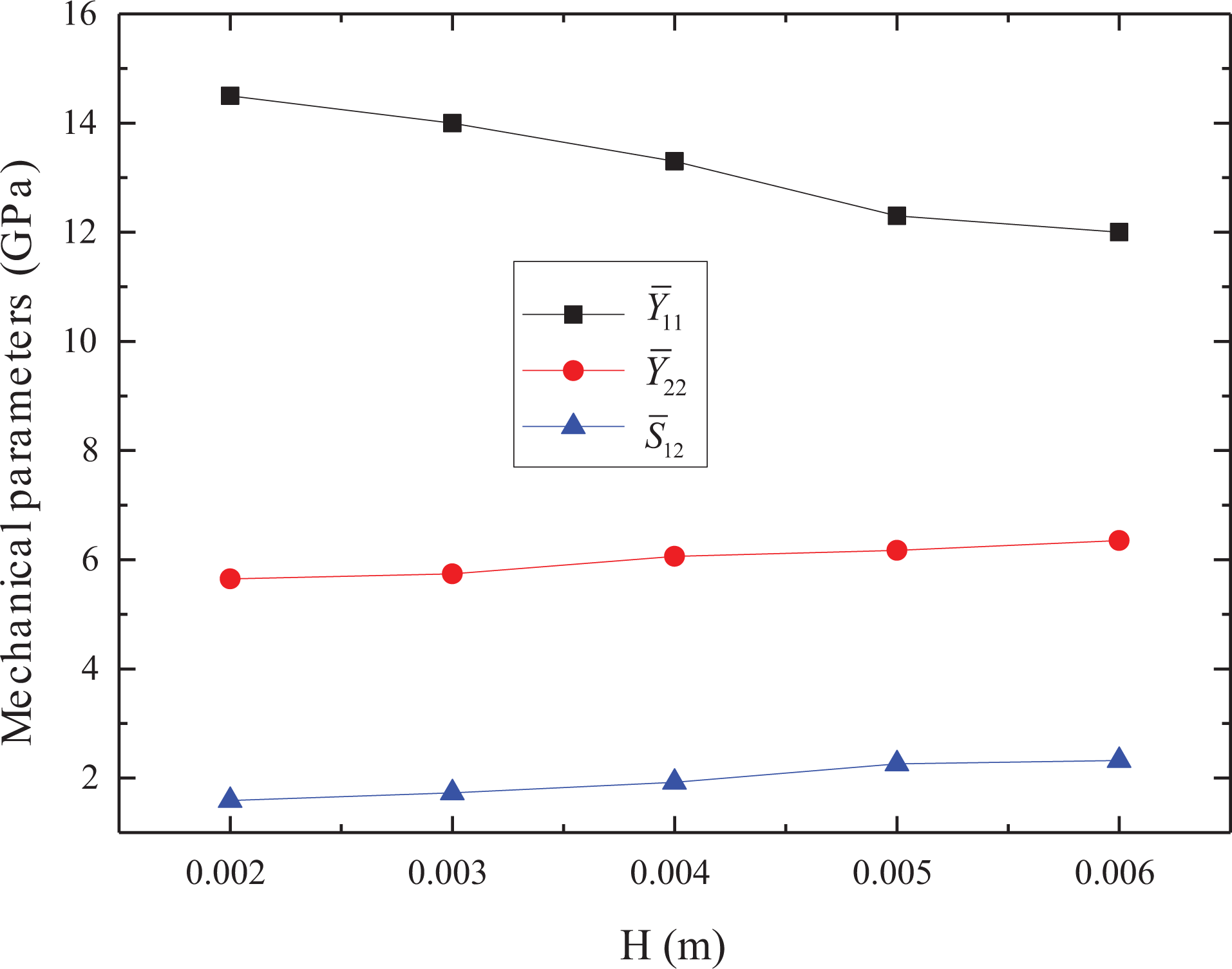
Variation of mechanical properties versus different geometric parameters of injection mold cavity.
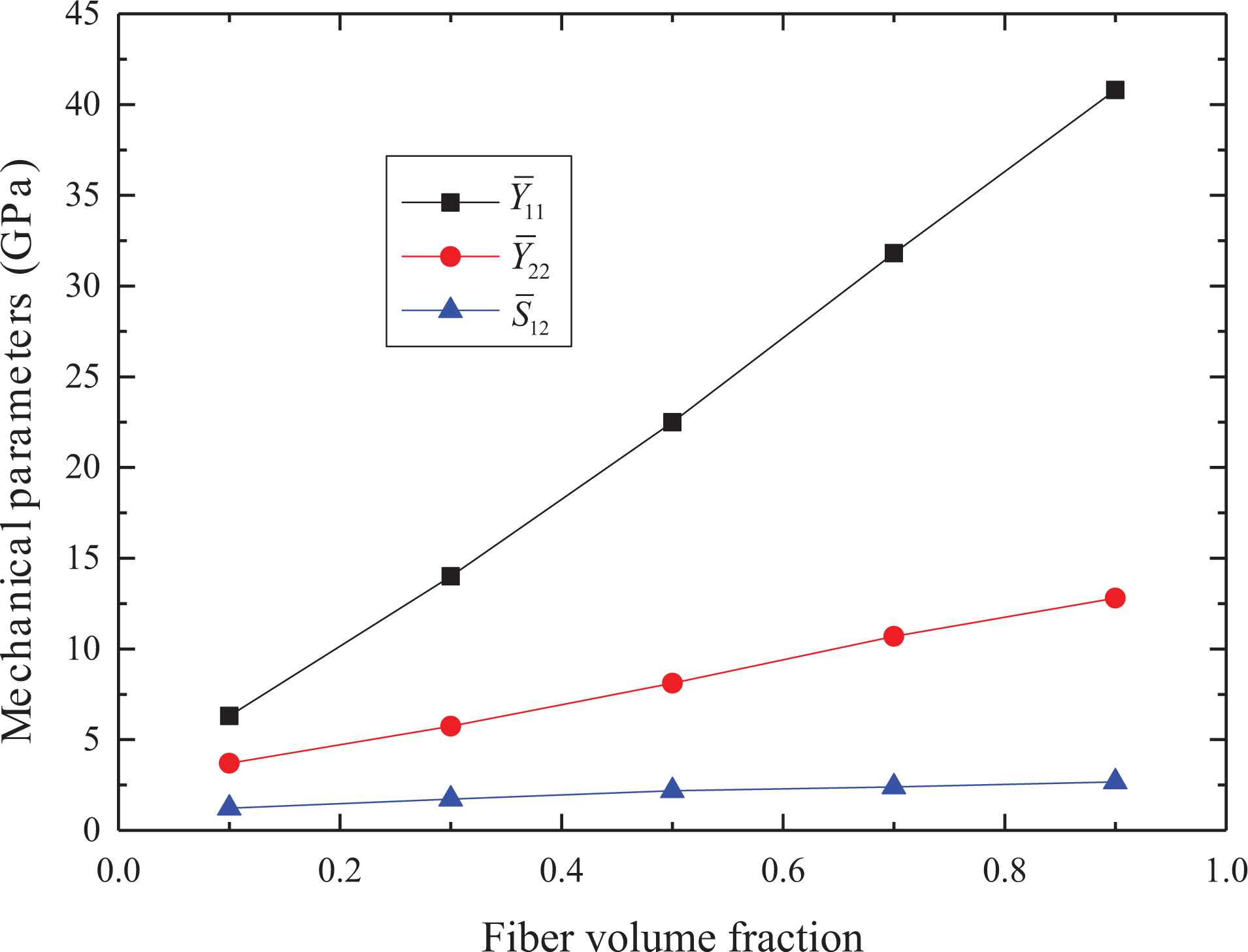
Variation of mechanical properties versus different fiber volume fractions.
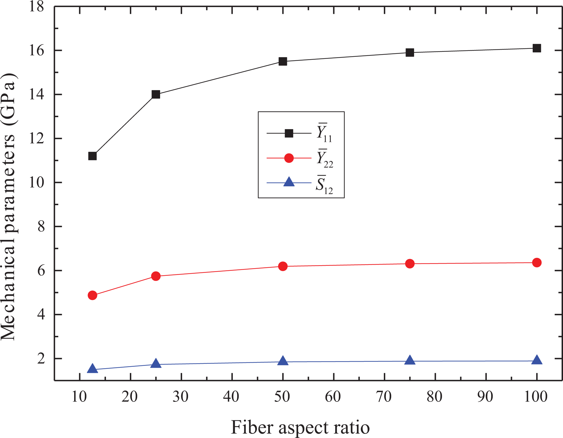
Variation of mechanical properties versus different fiber aspect ratios.
Conclusions
The mechanical properties of short fiber-reinforced polymer composites have been investigated through TPM method that couples the microstructure evolution and the properties of composites in practical processing in the study. Stable calculation was achieved for the multi-fields coupling problem by using the finite volume method based on the PISO algorithm. The RSC orientation evolution model was adopted for the analysis of 3-D fiber suspension flow characteristic during practical forming process. The evolution of fiber orientation distribution during the injection molding process of a fiber-reinforced flat plate was successfully predicted and the anisotropic shell-core-shell multilayer structure was obtained by using the established mathematical model and numerical algorithm. The mechanical properties of anisotropic composites including the Young’s modulus, the shear modulus, and the Poisson’s ratio were analyzed based on the Tandon–Weng model and the stiffness analysis. The Young’s modulus along longitudinal direction was found to be more than twice than that along transverse direction in the injection-molded flat plate. The mold cavity structure and fiber characteristics in practical processing process were found to directly influence the evolution of fiber orientation distribution and hence to affect the mechanical properties of final products. With the increase of the height of mold cavity, the longitudinal Young’s modulus was found to decrease for the reduction of fiber orientation degree. As for the fiber characteristics, the increase of fiber volume fractions and fiber aspect ratios can both improve mechanical property parameters of composite products especially along the longitudinal direction. Based on the TPM method proposed in the study, the structural response of composites in practical manufacturing process can be successfully evaluated and hence to correctly predict the mechanical property of fiber-reinforced polymer composites. Further work on how to improve the inner structure and the properties of fiber-reinforced composites products through more effective and optimum control of the processing conditions that are of significant interest to practical engineering problems can be conducted.
Footnotes
Funding
The author(s) disclosed receipt of the following financial support for the research, authorship, and/or publication of this article: This work is financially supported by the National Natural Science Foundation of China (No. 51675308, No. 51205231), the Natural Science Foundation of Shandong Province (No. ZR2012EEQ001), the Key Research and Development Program of Shandong Province (No. 2018GGX103014), and the Joint Funds of the Ministry of Education of China (No. 6141A02011705).