
Abstract
This work presents details of manufacturing and testing of a carbon fibre polyetheretherketone induction-welded hat-stiffened panel. Mechanical testing is carried out to evaluate the performance of the welded assembly and results are compared with similar testing of an adhesively bonded panel. The results show that the welded panel and the bonded panel had similar load-bearing capacity (<2% difference) and stiffness (<1% difference). Optical microscopy is used to verify the weld quality and identify manufacturing artefacts associated with induction welding. Inspection of the panel after welding shows that the induction welding process caused minor warpage, voids and delamination in the panel. The work addresses the lack of data relating to demonstrator scale welded assemblies in the literature, demonstrates that continuous induction welding is a suitable assembly technique for aerospace and automotive components under uniaxial in-plane compressive loading and identifies process-induced artefacts that may occur during induction welding.
Introduction
The cost of assembly of an aerospace wing box can represent as much as 40% of the total production cost of the part. 1 Assembly using mechanical fasteners is the primary method used for joining aircraft primary structures. 2 This is typically a manual process involving the alignment of parts using jigs and shims before drilling, deburring, cleaning and installing the mechanical fasteners. 1 Adhesive bonding is also used in aerospace manufacture, but it is also a labour-intensive manual process. The possibility of poor bonds due to inadequate surface preparation or uncured adhesive (kissing bonds), which are not detectable using conventional non-destructive testing (NDT), is a major disadvantage of the adhesive bonding process. 3 A study of the effect of surface preparation on bond strength of carbon fibre polyetheretherketone (CF-PEEK) samples showed that bond strength is strongly dependant on the surface preparation carried out. 4 These potential defects and the inability of NDT in detecting them lead to difficulties with certification of adhesive joints, thereby largely limiting their use to secondary loaded structures. 5 Due to these issues, additional fasteners are often incorporated into adhesively bonded joints, increasing weight, cost and production time.
Thermoplastic composite materials can offer superior toughness, better high temperature performance, longer storage life and better solvent resistance in comparison to traditional thermosetting composite material. 6 Thermoplastic composites represent a small market share of the aerospace sector. 6 This is partly due to manufacturing challenges (in particular, the high forming temperature and viscosity) when compared with their thermosetting counterparts. Recent advances in the automation of thermoplastic manufacturing, such as thermoplastic fusion bonding, stamp forming and automated tape placement, have demonstrated that thermoplastic composite manufacturing can be cost-effective. 7 Such manufacturing techniques are viable alternatives to autoclave manufacturing and traditional methods for joining composite subassemblies. Because of these advantages, thermoplastic composites are currently replacing thermosetting composites in many applications. 8
CF-PEEK is a semi-crystalline thermoplastic composite with excellent toughness, high temperature properties, solvent resistance and environmental resistance. 6 CF-PEEK can be manufactured using automated processes such as press forming and automated tape placement. 9,10 CF-PEEK has been shown to perform well in a simulated space environment 11 and there is ongoing research into its use in primary structures of launch vehicles, 12 in primary structures of commercial aircraft 13 and in cryogenic fuel tanks. 9 –14
Thermoplastic composite fusion bonding, or welding, involves the application of pressure and energy to the thermoplastic matrix at the weld line (interface between two previously unconnected subcomponents). During fusion bonding, heat melts the thermoplastic matrix of both components locally, and the pressure ensures intimate surface contact, causing fusion of polymer matrix chains in both components. This remelting of the composite laminate can cause deconsolidation. 15 The fibre network decompaction, void evolution due to gas expansion and surface tension and vaporization of moisture influence deconsolidation. 15 The pressure ensures that the individual composite laminates do not deconsolidate (i.e. structural disintegration of originally consolidated composites 16 ) when heated. 17,18 Once cooled, the thermoplastic matrix at the weld line solidifies, creating a strong continuous bond without the need for fasteners or adhesive. The weld type is generally classified based on the energy used to melt the material at the weld line. Three of the most promising forms of fusion bonding are ultrasonic, resistance and electromagnetic (induction) welding. 19
Induction welding is a type of fusion bonding where heat is induced at the weld line using electromagnetic induction. During welding, an alternating current passes through an induction coil creating an alternating magnetic field. This induces eddy currents in nearby conductive materials, which result in volumetric heating of these materials. Pressure can be applied by mechanical means via a roller, 20,21 tooling 22 or drawing of a vacuum. 21 With roller pressure (generally limited to flat panels), the weld line is initially heated by induction without the application of pressure before the consolidation roller passes over the part. 8,20,23 This means that the area heated by induction may deconsolidate locally before being reconsolidated by the roller. With vacuum pressure only, the maximum achievable pressure is atmospheric pressure (circa 1 bar) and a vacuum tight set-up is required.
Induction welding is currently used in the aerospace industry and has several advantages over adhesive bonding and joining with fasteners. These advantages including ease of automation, 7 weight reduction, 7 cycle time reduction, 24,25 reprocessability, 25 reproducibility (has been shown to provide single lap shear strength results with a scatter less than 1.5% of lap shear test value 26 ), fatigue life 4 and surface preparation reduction. 19 It has been demonstrated that induction welding is capable of automated joining of complex composite geometries. 27 Fokker Technologies (Papendrecht, The Netherlands) have manufactured several parts using fusion bonding. Part of the leading edge of the Airbus A380 wing is manufactured using resistance welding of glass fibre resulting in a net weight reduction of more than 20% as well as lower manufacturing costs. 28 The rudder and elevator of the Gulfstream G650 is manufactured using induction welding of carbon fibre polyphenylene sulphide (PPS) and mechanical fasteners. 7 The use of induction-welded CF-PPS in the Gulfstream Aerospace Corporation (Georgia, USA) G650 has resulted in a 20% cost saving and a 10% weight saving. 7 The weight reduction is achieved through the reduction of the number of fasteners as well as consequent reduction in ply build-ups around fastener holes. Fokker has stated with relation to thermoplastic composites ‘Our ambition is to step up from the products we already have to larger products that bear higher loads. For example, the complete tail section of the aircraft’. 29 The thermoplastic affordable primary aircraft structure research projects are aimed at developing technologies, including induction welding, to enable thermoplastics in primary structural applications. This project has demonstrated that thermoplastic materials and manufacturing methods, including induction welding, are suitable for the manufacture of primary structures. 13 Although induction welding of large scale, loaded parts is currently used in the aerospace industry, there is a lack of detailed published data on the topic. Details of part geometries, loading conditions, welder set-up, tooling set-up and test results have not been published. For many of the commercial parts that are either in service or under development, it is not clear to what extent induction welding has been used in the manufacturing process. In the case of the Gulfstream G650 tail section, joints between the beam webs and ribs are bolted and anti-peel fasteners are used at weld ends 7 Furthermore, none of the large scale, induction-welded demonstrators are manufactured using CF-PEEK. Induction welding is also used in automated manufacturing of unreinforced thermoplastic materials for high volume production of lower value parts, 30 highlighting the low cost and automation benefits of the process. This potential low cost may open up new markets such as automotive, sporting goods and construction.
During manufacture, thermal residual stress is created in composite components due to the mismatch in thermal expansion between the fibre and the matrix, the anisotropic thermal expansion of the plies (for non-unidirectional lay-ups only) and asymmetric cooling of the matrix. 31 For laminates with a balanced, symmetrical lay-up, where the laminate is not subject to large asymmetrical cooling, this residual stress does not lead to component warpage, as the stresses are symmetrical about the centre of the laminate. The localized thermal cycle (room temperature to above melt temperature and back to room temperature) associated with composite induction welding may alter the residual thermal stress distribution in the assembled component. In the heat-affected zone (the region around the weld line that has had its microstructure changed by the welding process), some of the matrix near the weld line is heated past its melting point. As the laminate approaches its melting temperature, it loses its ability to resist the residual stress in the laminate. The high residual thermal stresses combined with low material properties at high temperatures may lead to stress relief via component warpage, internal voids, local fibre buckling and microcracking. These defects may reduce joint performance and/or the functioning of the overall assembly may be altered. To the best of the authors’ knowledge, warpage of a structural assembly due to induction welding has not been reported in the literature; however, warpage has been reported by studies investigating resistance welding. 25,32 It should be noted that the heat-affected zone in resistance welding is quite different to induction welding. During resistance welding, the entire length of the weld line is above the melt temperature of the matrix, whereas in continuous induction welding, only a small part of the weld line is molten at any given time. As such, induction welding should be less susceptible to warpage.
Induction heating and welding of thermoplastic composites has been the focus of research for many years. 8,20 –23,25,26,30,33 –44 The majority of the work investigates welding small-scale simple geometries. Where testing has been carried out, it has involved coupon-level tests such as single lap shear, double cantilever beam, wedge and peel tests. A review of fusion bonding techniques, which also provides a comparison with adhesive bonding and mechanical fastening, gives single lap shear results from each method given in the study by Ageorges et al. 25 This review indicates that, based on lap shear tests, induction welding offers superior performance to adhesive bonding and mechanical fastening. Although small-scale lab trials and industry reports indicate that induction welding provides advantages in comparison to adhesive bonding, there is very little published work on demonstrator-level, induction-welded, structural components to confirm this. Only one component-level induction-welded part consisting of a carbon fibre PPS stiffened panel was identified in the literature, and the only testing carried out as part of this study was small-scale L-pull tests. 41 This highlights the knowledge gaps that currently exist in the literature relating to the structural performance of component-level induction-welded demonstrators.
For laminates reinforced with woven carbon fabrics, junction heating effects between the fibres are the dominant heating mechanism, 45 with heat being induced in loops in the carbon fabric, through which eddy currents can flow. Unidirectional stacked carbon fibre reinforcements generate significantly less heat when exposed to an alternating electromagnetic field compared to carbon fabrics 44 and are generally unsuitable for induction welding without the addition of a conductive material (referred to as a susceptor). 23 Thermoplastic composite laminates reinforced by glass fibre or unreinforced polymers cannot be induction welded without the use of susceptors at the weld line, as the materials are not electrically conductive. 37 Carbon fibre fabric, metal-coated carbon fibres, metal grids or doping the matrix with metal particles have been used to facilitate induction heating. 34 –46 In the current study, nickel-coated carbon fibre mat is used as a susceptor material.
Several studies have identified issues along weld-line edges due to local heating and pressure effects. 20,22,26,33 These edge effects can lead to local overheating causing process defects or alternatively incomplete welds due to insufficient heating or pressure. The induction welding process may produce defects, including voids in the weld line 22 and in the heat-affected zone of the composite subcomponents. 6 Careful control of process parameters such as pressure and temperature distribution is needed to minimize void and delamination formation. Minimizing the size of the heat-affected zone minimizes the volume in which process-induced defects can occur and Bayerl et al. 34 concluded that a susceptor material should ideally be placed at the weld line in order for heating to be localized at the weld line only. Applying cooling to the workpiece surface during the welding process has also been shown to reduce the size of the heat-affected zone. 47,48
The current work investigates two methods (induction welding and adhesive bonding) to join carbon fabric–reinforced PEEK stiffeners to a unidirectional carbon fibre–reinforced PEEK skin to form a stiffened composite panel. As the skin is unidirectional composite, a susceptor material has been placed at the weld line to generate sufficient heat to create a strong induction-welded joint and to minimize the size of the heat-affected zone. Macro-scale warpage and micro-scale defects attributed to induction welding are identified and the load-carrying capacity of the stiffened panel is tested and compared to that of an adhesively bonded panel. The work addresses knowledge gaps in the induction welding field relating to large-scale testing of CF-PEEK induction-welded components, by providing details of the manufacture, test and post-test inspection of an induction-welded CF-PEEK stiffened panel.
Materials and methods
A stiffened composite panel, consisting of a flat skin reinforced with hat stiffeners, is shown in Figure 1. This panel was designed as a demonstrator structure for composite joining in aerospace applications. Hat-stiffened panels are widely used in the manufacture of load-bearing aerospace structures due to their specific stiffness, strength and fatigue resistance. 49 The skin of each panel was manufactured from 60% fibre volume, unidirectional CF-PEEK. 50 The lay-up of the skin was symmetric (90/+45/0/−45) and contained 26 plies with unequal ply percentages and a thickness of 3.6 mm. The stiffeners were manufactured from 52% fibre volume 3K, five harness fabric reinforced CF-PEEK 51 consolidated using a heated hydraulic press. The lay-up of the stiffeners was (+45/−45, 0/90, 0/90)s with a thickness of 1.9 mm. CF-PEEK was chosen as the material for the current study due to its toughness, environmental resistance 6 and its performance in space environments. 11 CF-PEEK is a tough thermoplastic with a glass transition temperature of circa 143°C and a melt temperature of circa 343°C. The high melt temperature of CF-PEEK also leads to high thermal stress. The process cycle for all subcomponents was in accordance with the material supplier’s manufacturing specifications. Two stiffened panels have been manufactured and tested. The first panel was manufactured using a continuous induction welding process and the second using a standard adhesive bonding technique. The manufactured panels were then loaded to failure to determine their load-bearing capacity and provide a comparison between the two manufacturing techniques.
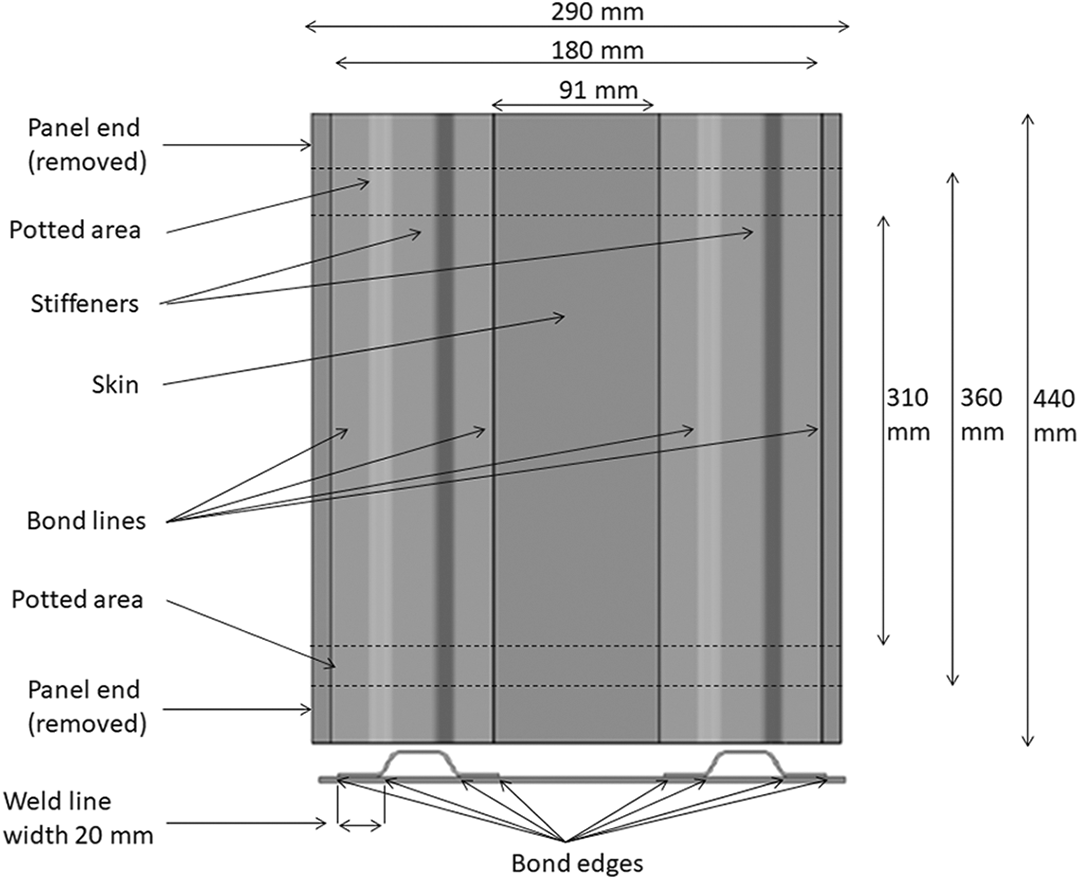
Geometry of stiffened panels showing features of the panels including the panel ends, potted area, test section and bond edges.
Induction-welded panel assembly
The stiffeners and the skin of the induction-welded panel are joined together using the continuous induction welding process shown in Figure 2. Alternating electrical current is supplied to the induction coil by a generator, which is controlled and monitored using the control unit and a data acquisition system. The coil is a ‘double-D’ geometry which is 18 mm wide by 32 mm long. A pneumatic pressure of 3 bar is supplied through the pressure bladder in the lower tooling and the upper tooling is stationary. A flat pressure plate is positioned between the bladder and the workpiece to ensure the pressures is evenly distributed. A transparent pressure plate is positioned directly above the workpiece; this reacts the pressure from the pressure plate and allows the surface temperature to be monitored using an infrared pyrometer. The upper pressure plate is cooled during welding using compressed air on the upper surface of the plate. The pressure is monitored using a pressure gauge with an accuracy of ±2.5%. The current system is capable of a continuous weld up to circa 1.5 m in length; however, the system could be upgraded to connect to a multi-axis robot arm in order to facilitate continuous welding of large complex geometries. A proprietary susceptor layer, highlighted in red in Figure 2, was supplied by EireComposites (Galway, Ireland). The susceptor, consisting of a nickel-coated CF mat embedded in PEEK film, 0.2 mm thick and 30 mm wide, was inserted along the length of the weld line. The susceptor was oversized by 5 mm either side of the weld line to eliminate susceptor misalignment during assembly.
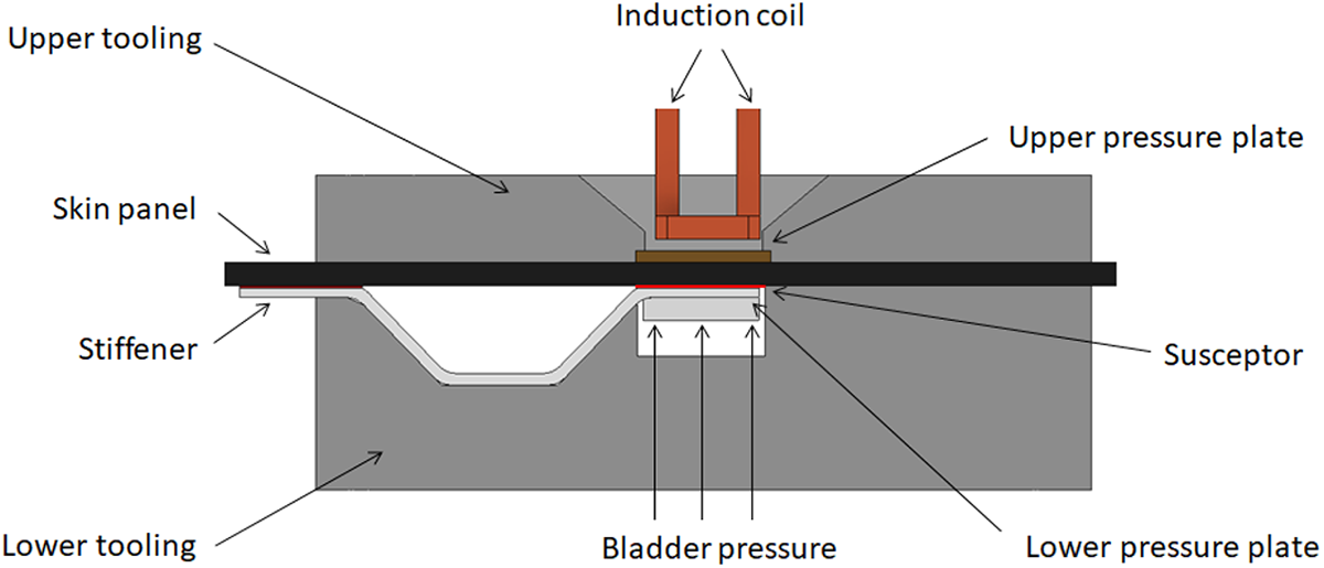
Section view of induction welding set-up.
The stiffeners and susceptor layer were aligned with the skin and placed in the tooling. The induction coil was positioned 5.6 mm above the weld line but not in contact with either of the subcomponents. An alternating current of 240–288 A at a frequency of 620 kHz was applied to the coil and it was moved along the length of the weld line at a rate of 1.75 mm per second. The welder current was controlled using a proportional–integral–derivative (PID) controller with the temperature on the top surface of the laminate used as the input set point. The set point of 195°C was selected, so that the entire contact area of the weld line was welded. To ensure no overheating occurred, trial welds were also carried out with a type k thermocouple located at the centre of the weld line. Figure 3 shows the temperature at the weld line as the coil moves over the weld line. The figure shows that the weld line is above the melt temperature for 24 s. The PID input temperature on the top surface of the skin laminate was measured during welding using an infrared pyrometer with an accuracy of ±2°C.
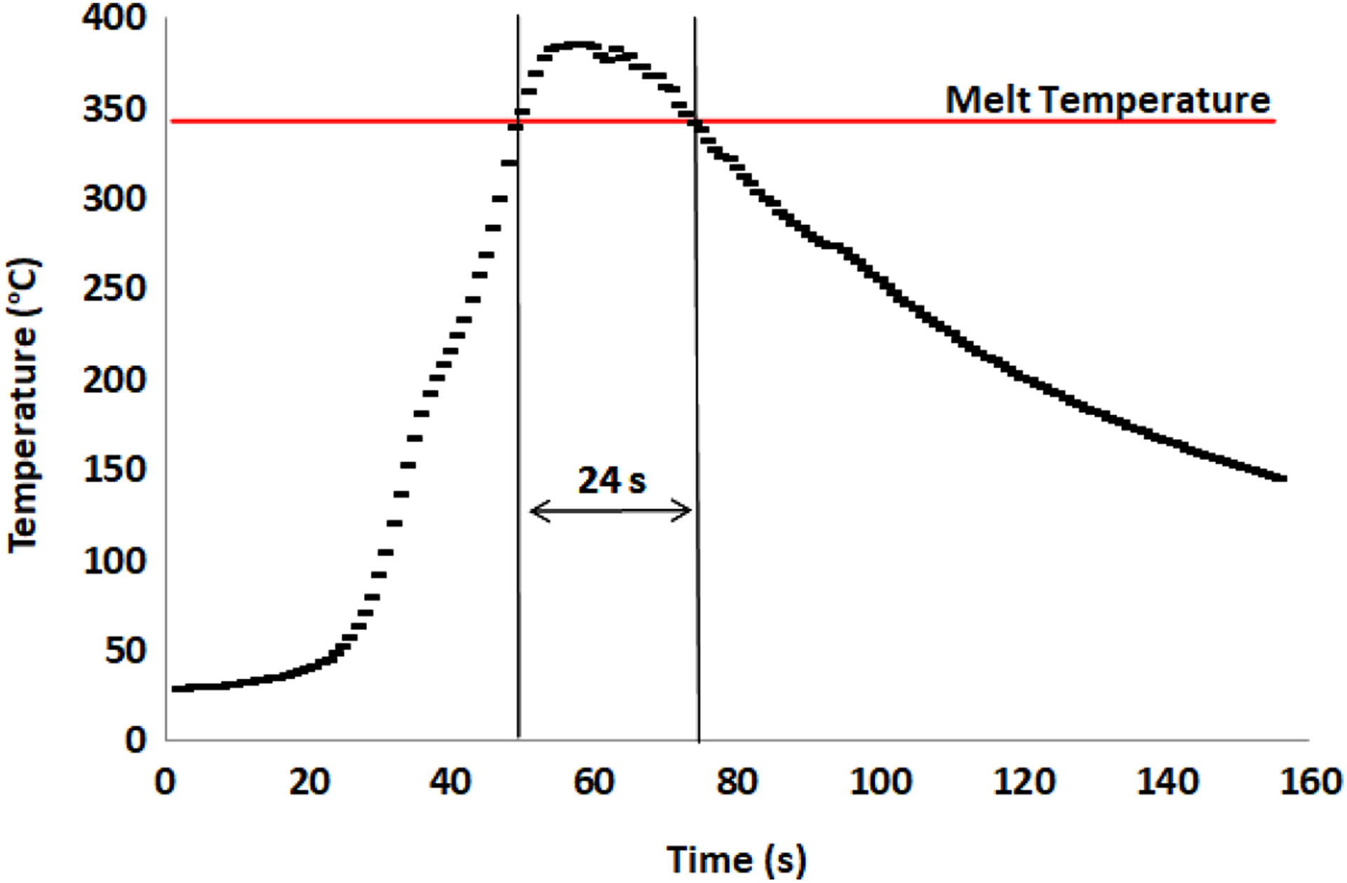
Weld-line temperature for trial weld, showing time above the melt temperature of CF-PEEK.
In order to eliminate any possible end effects at the weld run in and run outs due to overheating or under heating, as discussed by Mitschang et al., 33 a length of approximately 40 mm was removed from either end of the panel before mechanical testing. It was observed following welding that this area of the laminate had overheated. This area of the laminate was not part of the final structure.
Adhesively bonded panel assembly
A 3M scotch-weld 9323-150 two-part structural adhesive 52 recommended for bonding aerospace primary structures 53 was used to adhesively bond the second panel. Testing in accordance with BS EN 1465 54 showed that this adhesive provided lap shear strengths of 26 MPa for CF-PEEK samples. The surfaces were sandblasted and cleaned with acetone prior to bonding. The adhesive was mixed and applied in accordance with the manufacturer’s instructions. Glass beads of diameter 150 µm were included in the mixture to control the bond-line thickness. The adhesive was placed along the bond line and the stiffeners were aligned with the panel. The stiffeners were clamped in place and the adhesive was allowed to cure at 65°C for 2.5 h.
Inspection
Prior to assembly, all components were visually inspected for defects and NDT scanned using a Midas NDT ultrasonic through-transmission system. This verified that the parts were free from major issues such as large (>25 mm2) defects due to high percentages of local porosity, delamination or inclusion of foreign matter. Visual and dimensional inspections were also carried out to identify surface defects, such as dry fibres or surface imperfections, and to ensure that the panel thickness was uniform. The skin sections were inspected for flatness before assembly on an inspection table using a calibrated Mitutoyo digital dial with an accuracy of ±0.03 mm. After assembly, the panels were also visually and dimensionally inspected to check stiffener alignment and joint quality and to identify process-induced visual defects.
Mechanical testing of stiffened panels
The panel ends were potted in epoxy resin and machined flat to ensure that the load was transferred evenly over the entire surface area. This also allowed a cross-sectional view of the weld lines and bond lines to be visually inspected. Both panels were subjected to uniaxial in-plane compression loads along the axis of the stiffeners and testing was carried out using a Zwick (Ulm Germany) 400 kN screw-driven test machine, calibrated in accordance with ASTM E4-16, 55 class A. The crosshead displacement was measured using an linear variable differential transformer (LVDT) with an accuracy of ±0.01 mm. The test panels were placed between the upper and lower test platens and clamped in place as shown in Figure 4. 12 KFG 12-Ω uniaxial strain gauges were placed along the longitudinal direction to measure the panel deformation during loading. Both samples were then loaded in compression up to 60 kN to check the alignment of the test fixtures. Metal shims were placed between the test panels and the loading fixture to correct misalignment. Once the strain gauge data for all gauges indicated compressive symmetrical loading, the panels were loaded beyond the onset of buckling to ensure that buckling behaviour was elastic. Following this, the panels were loaded to failure.
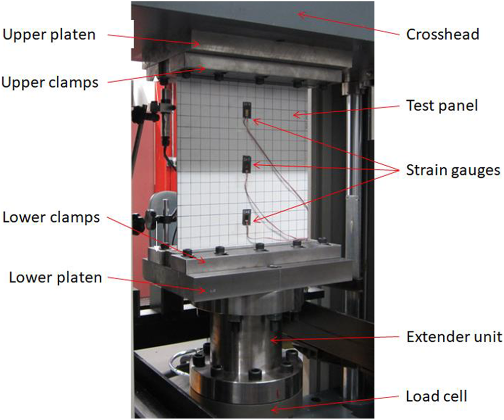
Test sample installed in test machine showing upper and lower platens.
Results
Pre- and post-assembly inspection
Pre-assembly inspection of the skins and stiffeners showed that the subcomponents were well consolidated with no large inclusions, delaminations or voids. Measurements of the flatness of the skins before joining showed that the skins were within a flatness tolerance of ±0.3 mm over the panel length. No defects or stiffener alignment issues were found during post-assembly inspection. Although detailed pretest microscopy was not carried out, visual inspection of the section view of the panel ends was carried out to identify any major issues. This inspection indicated that the weld lines and bond lines were well formed, with no perceptible voids or incomplete bonds. Flatness measurements of the adhesively bonded demonstrator taken after assembly showed that the panel remained within the flatness tolerance of ±0.3 mm and that no warpage had occurred during bonding. Flatness measurements of the welded demonstrator, presented in Figure 5, show that warpage up to 1.15 mm occurred during welding of the panel. The measurements were taken from the flat side of the panel and the warpage has curved the panel in the direction of the stiffeners. The warpage consists of a bowing along the loading axis of the panel. The ends of the welds, in the region of the panel that was removed, showed evidence of fibre and resin pushout and minor surface wrinkling on the stiffener foot. Visual inspection of the welded areas in the main body of the panel showed no perceptible surface discolouration or matrix or fibre push out at the edge of the part.
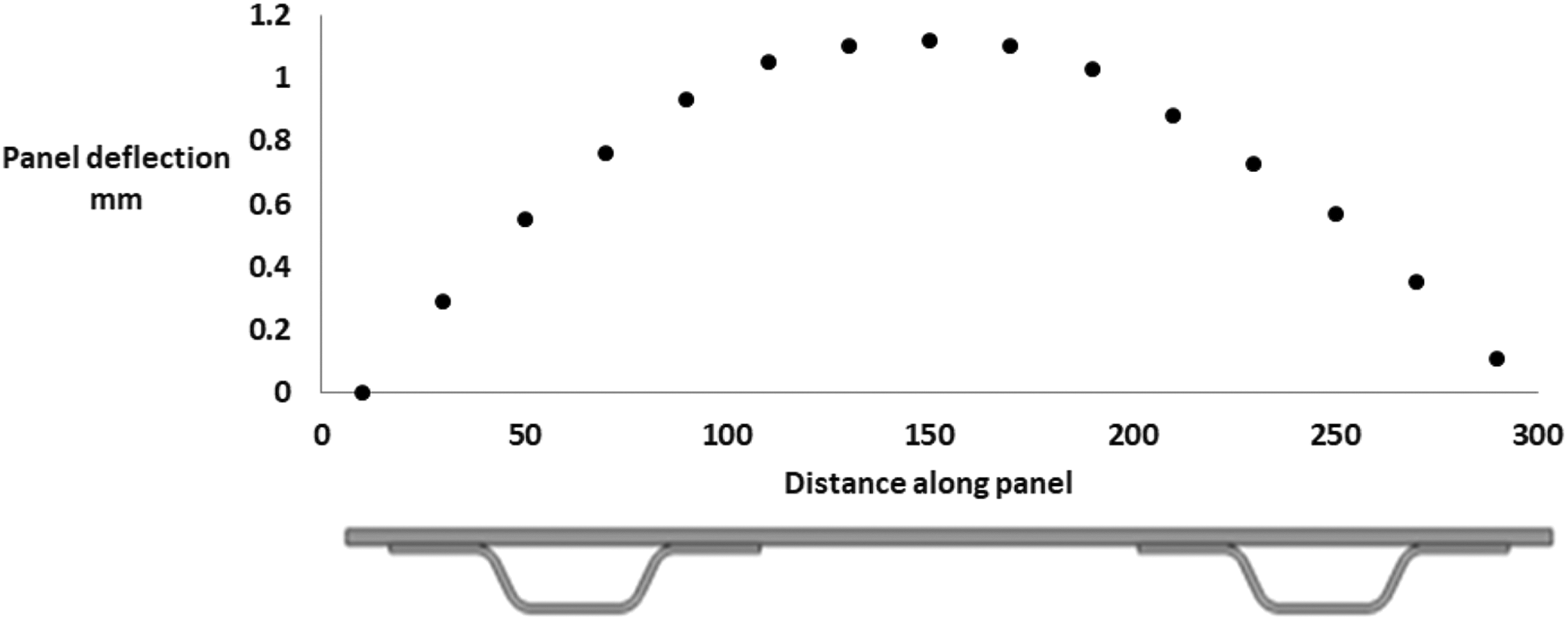
Graph of out-of-plane deflection of welded panel showing warpage of panel.
Testing
The buckling and failure behaviour of the panels during testing are illustrated in Figure 6. Figure 6(a) shows the adhesively bonded panel under load, prior to buckling. Figure 6(b) shows the panel in a buckled state and Figure 6(c) shows the panel post failure (a grid pattern has been painted on the surface to highlight panel deformation). Figure 6(c) shows that the stiffeners have failed across the mid-height of the panel and have detached from the skin of the panel. Comparing the panel buckling in Figure 6(b) to theoretical buckling in Figure 6(d) indicates that the panel behaviour is similar to that of a theoretical flat plate fully restrained against rotation at both ends.
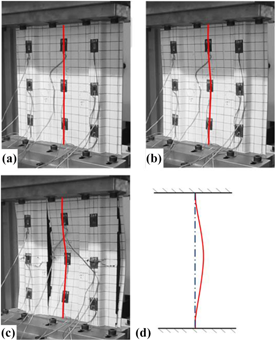
Images of adhesively bonded panel with panel deformation highlighted by a red spline. (a) Loaded prior to buckling, (b) buckled panel, (c) panel post failure and (d) image of buckling behaviour of a plate fixed at both ends with unbuckled deformation highlighted by the broken blue line and the buckled deformation highlighted by a solid red spline.
Figure 7 shows the load–deflection curves for the induction-welded and adhesively bonded panels. The induction-welded panel failed at a load of 370 kN, and the adhesively bonded panel failed at 361 kN. The load for both panels has been normalized against the failure load of the induction-welded panel. Trial loading to circa 80% of the failure load, and loading to failure is shown for each panel. The load–deflection graphs for both panels show an initial non-linearity due to bedding in of the test machine and fixtures. After this initial non-linearity, both panels show a linear load–deflection response up to circa 70% of the failure load. Above 70% of the failure load, the responses of the panels become non-linear and diverge slightly from each other. This non-linearity indicates that there is a loss of stiffness representing the onset of buckling. Comparison between the trial loading and the loading to failure of both panels shows that the load response of the panels was repeatable and there were no signs of damage in the panels. This indicates that the buckling was elastic. Following buckling, both panels failed at similar loads and crosshead displacements, with the adhesively bonded panel failing at 98% of the failure load of the welded specimen.
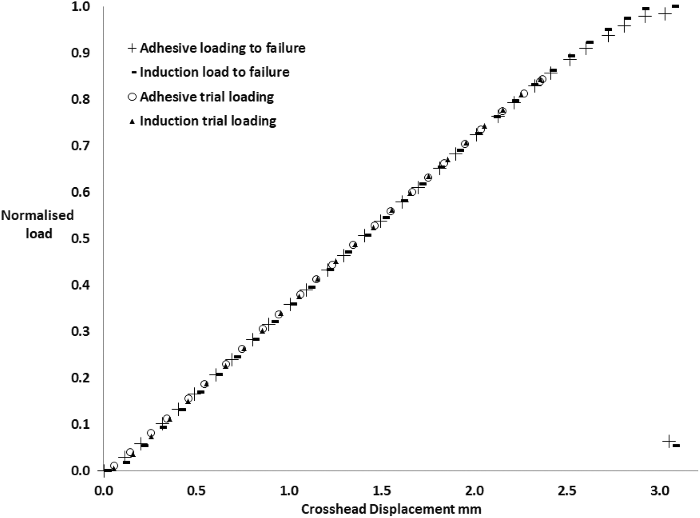
Load–displacement graph for the adhesively bonded and induction-welded panels showing trial loading and loading to failure of each panel. For loading to failure of each panel, the non-linearity due to buckling and post failure load-carrying capacity can be seen.
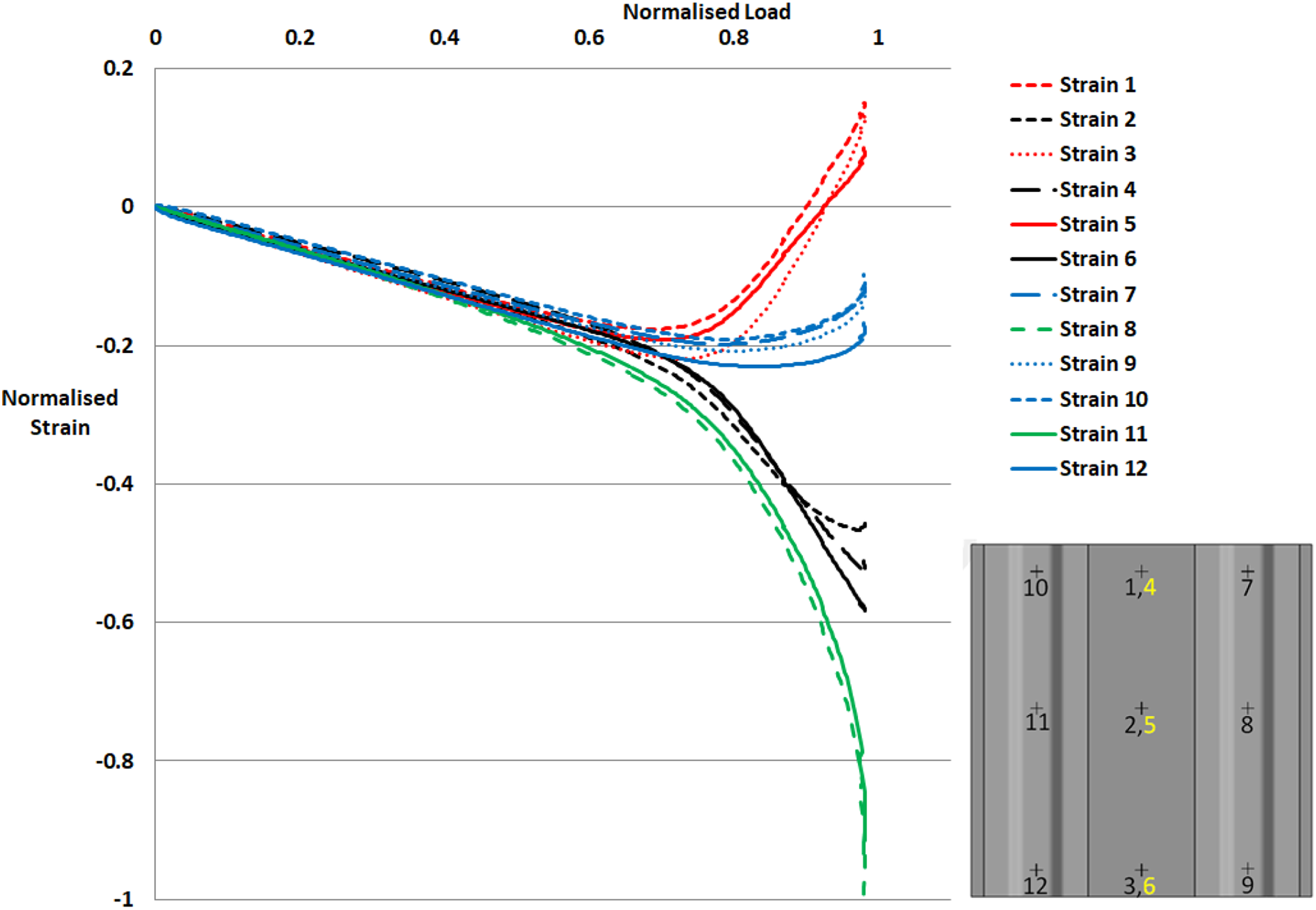
Figures 8 and 9 show the strain gauge response for loading to failure of both panels. The strain gauge data have been normalized against the maximum strain experienced by the panels. The grouping of all gauges at the start of loading and the response of gauges on each stiffener verifies that the panel was well aligned in the test machine. The figures show that the strain responses for equivalent gauges on both panels are similar. Gauges that behave in a similar manner have been colour coded in order for ease of comparison. The strain at any point in the structure is the sum of the strain due to the compression loading and the strain due to bending caused by the onset of buckling. Initially, the compressive strain in all gauges increases linearly with increased load. At approximately 70% of the failure load, both panels start to buckle. At this point, the rate of change of strain increases with increase in load for strain gauges 2, 4, 6, 8 and 11, while the rate of change of strain reverses for gauges 1, 3, 5, 7, 9, 10 and 12. As the load increases, the strain becomes positive for gauges 1, 3 and 5, indicating that the surface ply of this area of the panel goes into tension. This is due to the superposition of the bending strain due to buckling and the compressive strain in each gauge. The strain gauge data indicate that the panels with fixed ends behaved as indicated in Figure 6(d) and that buckling occurred gradually as the load increased.
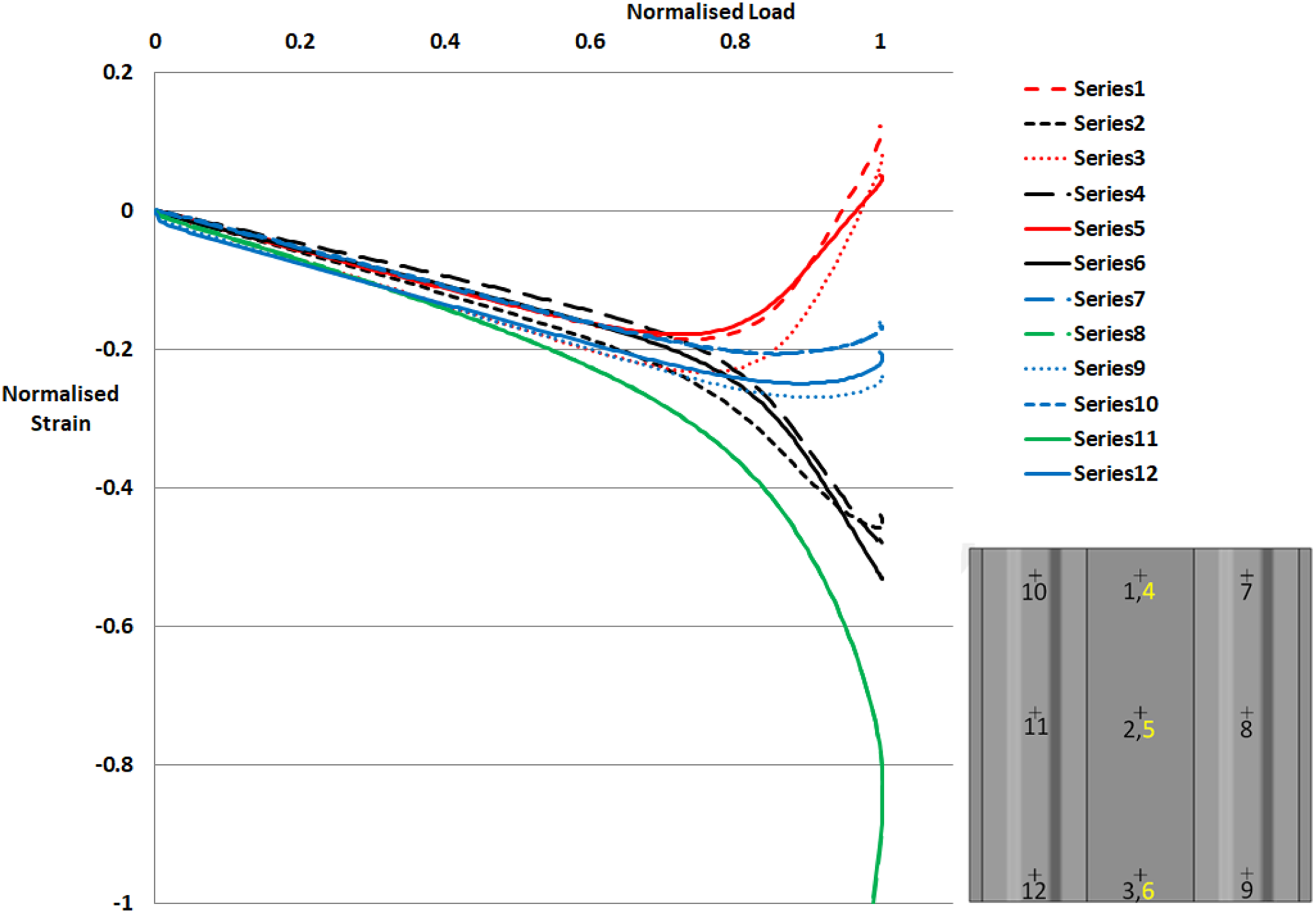
Strain gauge locations and response to loading for the induction-welded panel. The gauge locations are marked by a cross, black gauge numbers are located on the stiffener face of the panel and yellow numbers are located on the flat face of the panel. All gauges are orientated in the loading direction. Note that the data for gauges 8 and 11 and gauges 7 and 10 overlap one another and cannot be distinguished from one another in the above graph.
Strain gauge locations and response to loading for adhesively bonded panel. The gauge locations are marked by a cross, black gauge numbers are located on the stiffener face of the panel and yellow numbers are located on the flat face of the panel. All gauges are orientated in the loading direction.
Several acoustic emissions were heard prior to failure in both panels. The maximum compressive strain, which exceeded 12,000 microstrain (1.2% strain) for both test panels, was measured at the mid-height of the panel on the crown of the stiffeners as shown in Figures 8 and 9. This strain measurement is in the region of the ultimate compressive strain to failure of the fabric material 51 and indicates that the stiffeners failed initially. Following the initial failure, the stiffeners detached from the skin, along the mid-height of the panel, and transferred the load into the skin causing buckling of the unidirectional skins of the panels.
Post-test inspection
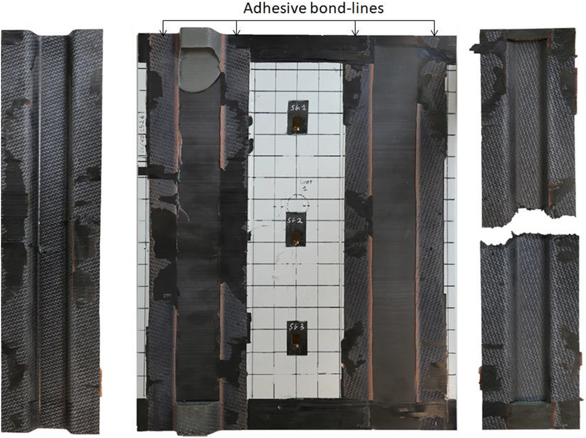
Post-test inspection of the welded panel showed that the stiffener had detached along the length of the panel. Figure 10 shows the welded panel disassembled following failure. The potted ends of the panel were removed from the panel and micro-sections were extracted at locations 1 to 8 in Figure 10. For the purpose of this discussion, adhesive failure is failure at a weld surface between the susceptor and the composite surface, cohesive failure is failure in the susceptor and substrate failure is failure in the substrate of the composite. The stiffeners of the panel have fractured across their mid-height at strain gauge locations 8 and 11. Areas that have failed via adhesive failure between the stiffener and the susceptor are highlighted in yellow. Areas that have failed via adhesive failure between the susceptor and the panel are highlighted in red. For the remainder of the weld line, the substrate of the panel failed and the majority of the weld lines remained intact. In general, the joint failed adhesively between the CF-PEEK and the susceptor material at the mid-height of the panel. Away from the mid-height of the panel, the failure transitions to substrate failure in the skin panel. Much of the top ply, and in some areas the second ply, has remained welded to the stiffeners. In areas where the first ply has been removed, the welded area of the composite is highlighted by a slight change in texture and appearance as seen in Figure 10. The areas highlighted in green and blue contain several defects which are examined in more detail in Figures 11 and 12.
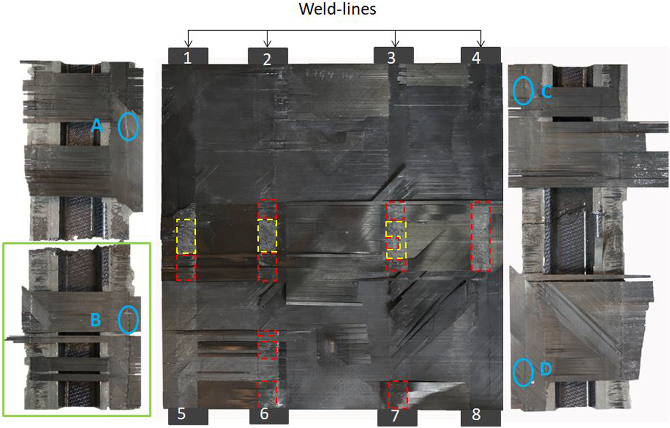
Welded panel dismantled following testing, showing the skin of the panel in the centre and the stiffeners on the right and left. The locations marked 1 to 8 indicate the areas from which micro-sections were extracted. The areas highlighted by yellow dashed lines are areas that have failed via adhesive failure between the stiffener and the susceptor. The areas highlighted in red dashed lines have failed via adhesive failure between the susceptor and the panel. The areas highlighted in green and blue solid lines are shown in more detail in the following figures.
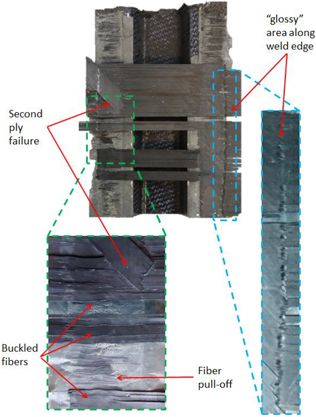
Close up of welded-stiffener fracture surface highlighted in green in Figure 10 showing second ply failure, buckled fibres and glossy weld edge appearance.
Figure 11 shows a close up of the bottom of the left-hand stiffener from Figure 10, which highlights the second ply failure, buckled fibres, on the top ply of the laminate, and the glossy appearance at the edge of the weld line. The area in Figure 11 where the panel has failed via adhesive failure between the susceptor material and the skin shows that fibres have been pulled off the surface of the top ply along the centre of the weld line. This indicates that a strong bond was formed between the weld line and the laminate skin. Fibre pull-off was also evident in areas where the weld failed via adhesive failure between the stiffener and the susceptor again indicating a strong bond. The majority of the failure occurred either by adhesive failure between the skin and the susceptor or failure of the substrate of the panel.
Figures 10 and 11 show that all the interply fracture surfaces have a matt appearance, apart from some of the edges of the weld lines where the material has a glossy surface. Figure 12(a) to (d) shows microscopic images of the glossy areas highlighted by the green circles in Figure 10. Figure 12(e) shows a typical fracture surface away from the weld lines between the first and second plies. Figure 12(a) to (d) shows a distinctly different fracture surface to Figure 12(e). The PEEK matrix, located on the fracture surface, has round edges at several locations showing that it was formed by thermal processing as opposed to fracturing of the part. This shows that these locations represent voids/delamination in the part which were created during thermal processing. The glossy area at the edge of the weld line is the only area that showed these patterns.
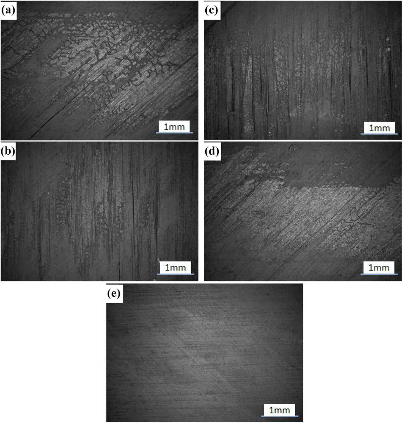
(a) to (d) show the fracture surface at the glossy area at locations A to D in Figure 10. Each image shows the formations of melted PEEK that indicate voids/delamination were formed during thermal processing. (e) Shows a typical fracture surface away from the welding. Fracture surfaces (a) and (d) are between the second and the third plies. Fracture surfaces (b) and (c) are between the first and second plies. PEEK: polyetheretherkeytone.
Eight welded sections were extracted from ends of the failed panel and two sides of each section were polished in order to inspect the microstructure of the weld and the surrounding composite. The sections were removed after testing but prior to panel disassembly to preserve any intact welds at the panel ends. Inspection of the weld lines showed that the weld lines were well consolidated with a low void content. Figure 13 shows a representative micro-section of a weld line taken from the top of location 1 in Figure 10. The figure shows an intact, well-consolidated, weld line between the stiffener and the skin with very few voids. The figure also shows voids in the stiffener, delaminations and one void in the skin, and potential stress concentrations at the weld edges. The location of the delaminations in the skin along the edge of the weld line between the first, second and third plies coincides with the glossy areas highlighted in Figures 11 and 12. Of the 16 micro-sections examined, 7 contained voids at the edge of the weld line in the top plies of the skin, similar to those shown in Figure 13, while 2 did not contain voids at this location and 7 were inconclusive as the welded joint had failed. This indicates that the glossy areas of the panel represent delaminations in the top plies.
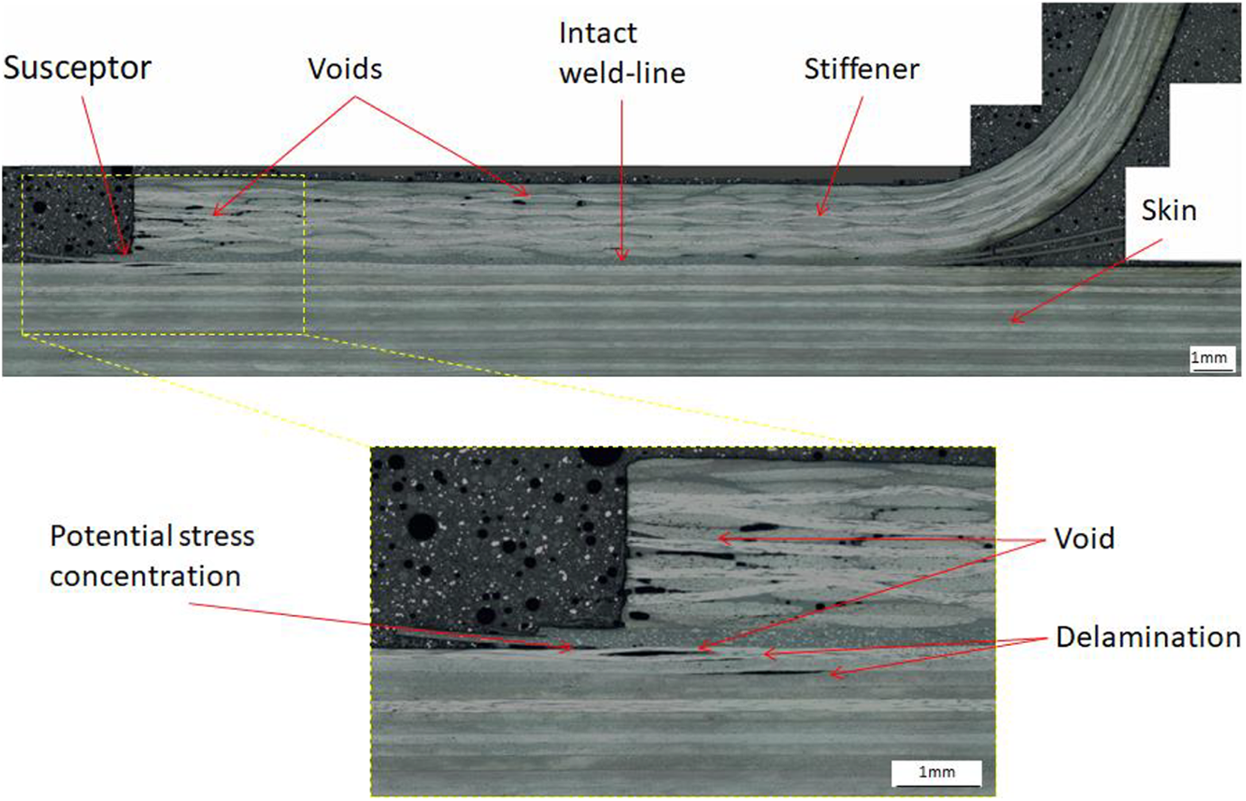
Micro-section of stiffener and skin, taken from the top of location 1 in Figure 10, showing intact weld-line and process-induced voids and delamination.
Figure 14 shows a micro-section of a failed weld line taken from the bottom of location 1 of Figure 10. On the left-hand side of the weld line, the weld has failed adhesively between the susceptor and the skin of the panel. Near the centre of the weld line, the failure transitions through the second ply and causes a delamination along the centre of the weld line. The image shows that the failure has transitioned through the first ply via fibre breakage and through the second ply via matrix microcracking. Microcracking can also be seen in the third ply of the laminate. On the right-hand side of the weld line, the failure transitions back through the first ply causing a delamination between the first and second plies. Figure 14 also shows potential stress concentrations at both edges of the weld, potential stress concentrations were found on all welds examined. There was no evidence of process-induced defects seen in the skin of the laminate at the location examined; however, this may be because the delamination passed through or initiated at the defect and is no longer visible. Although there were local areas of high porosity at the free edge of the stiffener, a void analysis of the entire welded area of the stiffener foot from Figures 13 and 14 showed that the void content of the stiffener was below 1.5%. The void analysis was carried out by applying a threshold to a micro-section image of the stiffener and calculating the number of pixels below this threshold as a percentage of the total pixels using ImageJ. 56
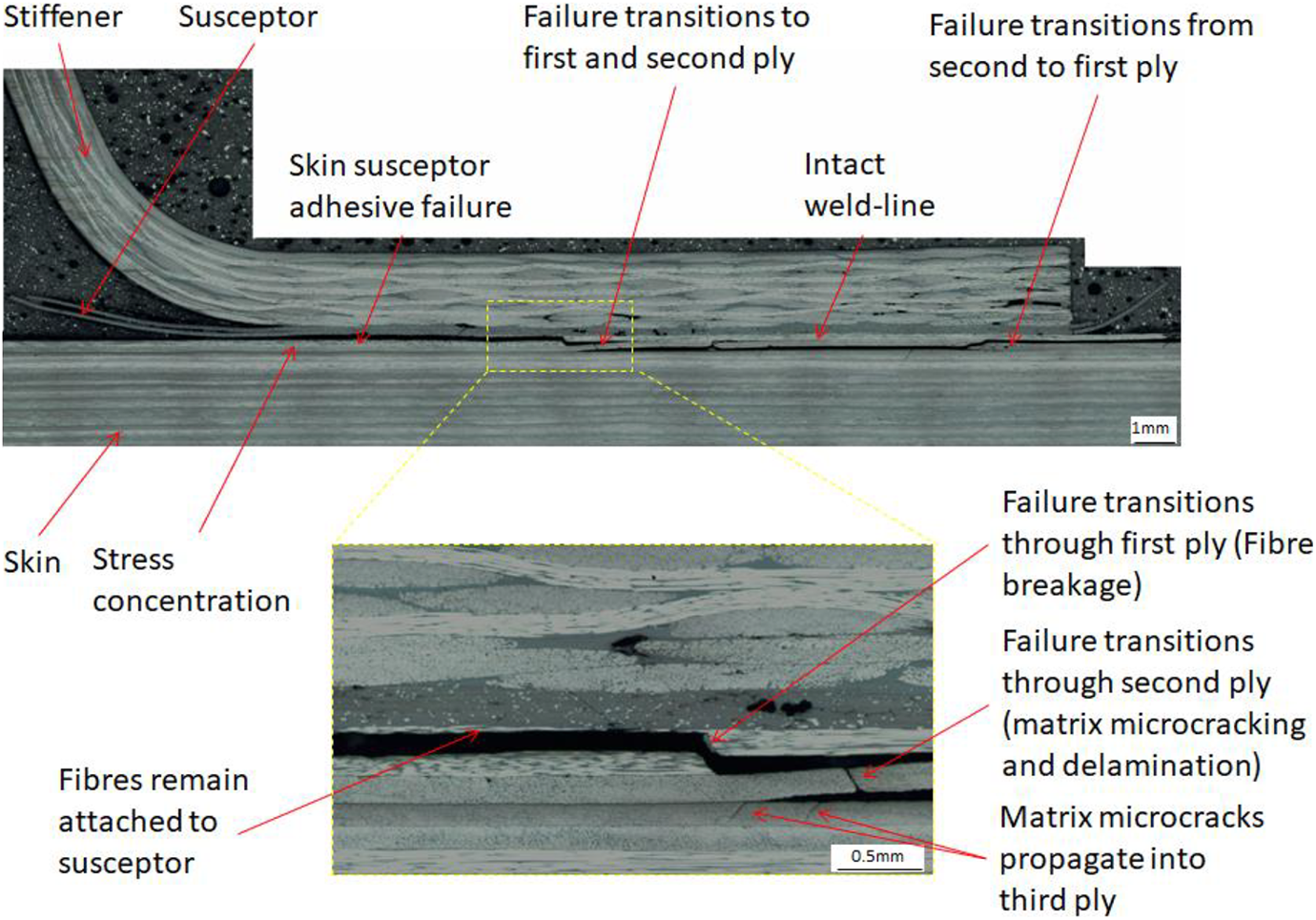
Micro-section of failed weld line, taken from the bottom of location 1 in Figure 10, showing adhesive failure between the susceptor and the skin and failure in the first and second plies of the skin.
Figure 15 shows a micro-section taken from a weld run in at the end of the panel, where overheating was observed following welding. This area is part of the area that was removed prior to testing. The figure shows several process-induced defects in the heat-affected zone in both the stiffener and the skin of the panel with defects in the skin located as far as 15 plies into the panel. At the edge of the stiffener, fibres and matrix have been pushed out and have deformed locally. Voids and delaminations can be seen in the skin of the panel, while voids can also be seen in the stiffener and in the weld line itself. The voids and delaminations in the skin form a ‘deconsolidation front’ similar to that shown by Ageorges and Ye. 57 This offcut illustrates the potential problems that occur when an area is overheated during welding and highlights the need for process control during welding.

Micro-section of an offcut taken from the end of the panel showing an area where the weld line was overheated. Process-induced defects can be seen throughout the heat-affected zone of the laminate.
Figure 16 shows the adhesively bonded panel disassembled following failure. Post-test inspection of the adhesively bonded panel showed that the stiffener had detached along the full length of the panel. The stiffeners of the panel have fractured across their mid-height at strain gauge locations 8 and 11. Areas where the pink adhesive can be seen on the surface of the panel failed due to adhesive failure between the stiffener and the adhesive. The remainder of the bond failed due to adhesive failure between the skin and the adhesive. Close examination of the bond area showed that the adhesive had pulled out individual surface fibres and caused local delaminations in the bond area. This indicates that a strong bond had been formed between the adhesive and the subcomponents along the full length of the stiffener.
Adhesively bonded panel dismantled following testing showing the skin of the panel in the centre and the fracture surface of the stiffeners on the right and left.
Discussion
The strain gauge data and failure loads reached for both panels showed that both panels behaved in a similar manner. This indicates that induction welding is comparable to well-bonded structural adhesive and that it is suitable for the manufacture of CF-PEEK primary components.
Post-test inspection of the welded panel showed that the welded joints had failed via (i) adhesive failure between the stiffener and the susceptor, (ii) adhesive failure between the skin and (iii) delamination of the top plies of the skin. Over much of the panel, the welded joint remained intact and failure occurred in the second and third plies of the skin. This indicates that a strong joint was formed by the welding process. Optical microscopy of the weld line showed that the weld line was well consolidated. The edge of the weld line, where the susceptor material joined to the composite, contained sharp edges that may act as stress concentrations. These stress concentrations are difficult to avoid and could lead to reduced joint strength in certain loading conditions.
The heat-affected zones in both the skin laminate (unidirectional) and the stiffener (fabric) were inspected; process-induced defects were found in both stiffeners and skins. Visual examination of the skin showed that the surface ply had buckled locally under the welded area, as shown in Figure 11, and a glossy area had formed between the first and second plies, as well as between the second and third plies. The glossy areas on the fracture surface were examined under a microscope and revealed melted PEEK formations between the first, second and third plies. Optical microscopy of nine intact micro-sections removed from the panel revealed the presence of voids and delaminations at the weld edge in seven out of the nine samples. The glossy area on the panel and the delaminations identified in the panel were found to be in the same location as the voids and delamination. This indicates that the glossy areas on the fracture surface of the plies are delaminations between the plies. The locations of these defects at the edges of the weld line indicate that the defects were caused by the welding process. Visual examination of the entire fracture surface has shown that the glossy regions were present between the first and second plies, as well as between the second and third plies, and were up to 3 mm wide in places.
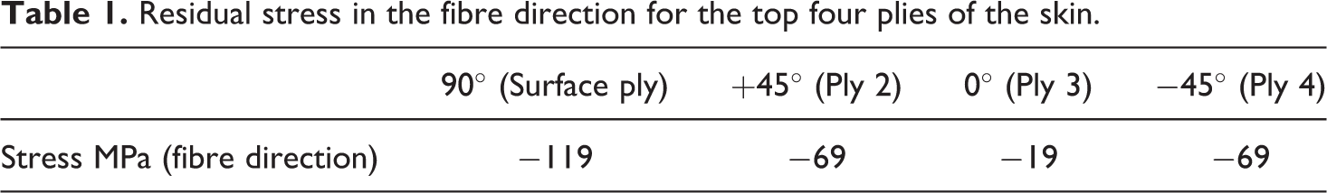
In order to investigate the possible cause of the fibre buckling and delaminations in the heat-affected zone, the residual stress of the top four plies of the laminate was investigated. During manufacture, the main body of the skin laminate contracts during cooling. Due to anisotropic thermal expansion of the individual plies, macro-mechanical residual stress builds up as the laminate cools from the stress free temperature to room temperature. The macro-mechanical residual thermal stress in the fibre direction for the top four plies is given in Table 1. The values were calculated using composite laminate theory (CLT) and verified using a 3-D finite element simulation. The material properties given in the study by Grogan et al. 58 were used for the analysis. Using elastic CLT has been shown to give good approximation or residual stress 59 ; however, more accurate material properties and a viscoelastic analysis verified by experimentation would be needed to accurately predict the macro-mechanical residual thermal stress. The analysis indicates that there is a significant compressive thermal stress present in all plies and that the compressive stress in the fibre direction for the top ply of the laminate is nearly twice that in the ±45° plies, and nearly five times that of the 0° plies.
Residual stress in the fibre direction for the top four plies of the skin.
During welding, the matrix of the surface plies melts and these plies lose their compressive load-carrying capacity. If the pressure constraining the plies is not adequate, the fibres may buckle locally in the heat-affected zone 16 due to compressive thermal stress caused by the temperature gradient in the laminate. This may explain the in-plane buckling observed on the surface of the laminate under the welded joints and the delaminations formed in the top plies of the laminate. Two of the nine specimens examined contained no delamination. This shows that these defects may be avoided with tighter process control and highlights inconsistencies in the current set-up. Future work will investigate the coil geometry and susceptor material consistency in order to eliminate these defects.
Visual examination of the stiffener showed no surface defects. A void analysis of the foot of the stiffener showed that the void contents were below 1.5%. It is not clear whether these voids are caused by the welding process or if they were already present in the stiffener before welding. During stiffener manufacture, the fabric material is compressed in a hydraulic press and heated in order to consolidate the material. Once the part has cooled sufficiently, the compression constraint is removed and the matrix of the laminate must resist the decompaction force of the carbon fibre. 15,18 During welding, the matrix of the laminate is melted and the decompaction force may cause deconsolidation of the laminate. As with the skin laminate, if the pressure constraining the fibres is not sufficient, deconsolidation may occur.
Dubé et al. 32 have proposed that a reduction in pressure at the free edge is responsible for the formation of voids. During the welding process, much of the matrix of the stiffener foot is melted and the edge of the stiffener is not constrained. This results in the melted composite deforming outward at the free edge and the composite no longer fully reacting the pressure applied by the welding rig. The lower pressure then allows voids to form in the surrounding composite. This may explain why voids and delaminations were found in the skin below the free edge of the stiffener but not on the other edge of the weld. Further work is needed to say with certainty that this is the main cause of the observed voids.
Residual stress has been highlighted as a major factor in deconsolidation of carbon fibre re-enforced thermoplastics. 15,16,60 The local buckling defects and voids identified in the current paper are consistent with these observations. Reducing the residual stress, by tailoring the lay-up so that plies with the lowest residual stress are located at the surface, or by controlling the cooling during manufacture 61 may lead to a reduction in process-induced defects.
Measurement of the panel geometry after welding showed that the panel had deformed during the welding process. Warpage may occur during any thermal process; therefore, it is not surprising that some warpage occurred in the current study. Fibre buckling is a means of compressive stress relief, and the presence of local buckling indicates that compressive stress has been reduced on the stiffener side of the skin. This creates an asymmetric stress distribution in the laminate which may cause warpage of the panel toward the stiffener of the panel. Other factors that may affect buckling are the clamping conditions, thermal expansion mismatch between the stiffener and the skin or a change in crystallinity in the heat-affected zone. During manufacture, the ends of the panel were subject to excessive heating which caused major defects in this area. Although this area was removed from the laminate, it is possible that this approach increased the warpage in the panel. Micro-sections were examined in an area of the panel that was overheated. The examination showed some process-induced defects throughout the skin and stiffener. This examination highlighted the need for improved process control in order to avoid damage to the subcomponents during assembly. End effects have been identified in several studies, 20,33 but there is little published work quantifying their effects. In order for induction welding to become a standard manufacturing technique, end effects will have to be quantified and methods for mitigating their effects developed.
Reducing the size of the heat-affected zone and achieving better temperature uniformity across the width of the weld line would likely reduce the defects that have been identified in the current paper. Several improvements could be made to the current set-up. The coil design used here is a ‘double D’ design which has been shown to give a heating pattern which is a mirror image of the coil, with the hottest point at the centre of the coil. Improving the coil design to give better uniformity across the weld line would reduce the size of the heat-affected zone and also the thermal gradients in the laminate. Adding cooling channels to the tooling to achieve better cooling of the workpiece during welding would also reduce the size of the heat-affected zone at a cost of tooling complexity.
The study has shown that the welding process may cause defects in the final part. These defects are not identifiable through non-destructive visual inspection. In order for the induction welding process to be used in aerospace applications, better process control, process monitoring and NDT procedures are needed.
Post-test inspection of the adhesively bonded panel showed that the joint failed via (i) adhesive failure between the adhesive and the stiffeners and (ii) adhesive failure between the adhesive and the panel. The bonded joint also caused the surface ply to delaminate in the area under the bond line, indicating that a strong bond was formed. No process-induced defects were found.
Conclusions
The current work compares a single induction-welded stiffened panel to a single adhesively bonded stiffened panel under uniaxial in-plane compression loading. The materials used, pressure application method, testing and post-test inspection have provided a valuable insight into a novel manufacturing method. Several issues not previously highlighted in the literature have been identified. The following conclusions can be drawn from the work.
The work carried out in this study indicates that the induction welding process is a suitable assembly process for the manufacture of CF-PEEK primary structural components. Mechanical testing showed that the stiffness, ultimate load, failure location and buckling behaviour of the induction-welded panel were similar to an adhesively bonded panel. The mechanical performance demonstrated here, combined with its advantages over traditional bonding, make it a promising manufacturing method for bonding primary aerospace structures. Further studies, however, involving multiple demonstrators under a variety of loading conditions are needed to further validate the induction welding process for primary load-bearing structures.
The process demonstrated in the current study is capable of high-quality, continuous induction welding of a hat-stiffened panel, representative of a typical aerospace primary structure.
Both glued and induction-welded thermoplastic panels were shown to be capable of repeated loading past the onset of buckling without any indication of damage to the panel.
The failure of the weld line during panel structural failure caused damage into the third ply of the skin, indicating that a strong bond had been formed between the skin and the stiffeners.
The welding process caused warpage, local fibre buckling, voids and delamination formation in the skin of the panel. These defects did not significantly affect the mechanical behaviour of the panel in the current loading scenario.
Process-induced defects that could affect the mechanical performance of the laminate were not apparent during visual examination. This highlights the need for investigation of NDT techniques suitable for verifying the induction welding process and for tight process control and quality procedures in order to verify joints.
Potential stress concentrations created during welding were identified. These defects occur where the susceptor material fuses with the subcomponents at the edges of the weld line. These defects are intrinsic to the welding process, and as such, their effect on different loading scenarios should be investigated.
Examination of an area of the laminate that was overheated at the start of the welding procedure showed the potential to create a poor bond and to damage the surrounding composite.
Footnotes
Acknowledgements
The authors would like to acknowledge Dr Tomas Flanagan, Dr Oscar De La Torre and Mr Colm Walsh for their assistance.
Funding
The author(s) disclosed receipt of the following financial support for the research, authorship, and/or publication of this article: This work was financially supported by the Irish Research Council (IRC) Employment-Based Postgraduate Scheme, the European Space Agency and Science Foundation Ireland (SFI) through the MaREI Centre (Grant No. 12/RC/2302).