
Abstract
Discontinuous Long Fibre (DLF) composites, composed of randomly-oriented strands of chopped unidirectional pre-impregnated tape, have been used in the aerospace industry to produce intricate, net-shape parts with complex features – replacing complicated metallic brackets with single, lightweight parts. Carbon/PEEK DLF composites suffer from warpage problems driven by several factors including their high processing temperatures and semi-crystalline matrix shrinkage. This work aims to characterize warpage of thin-gauge parts and pursue mitigation. Results showed that the magnitude of warpage reduces with decreasing strand size and increasing thickness. At thicknesses greater than 2 mm, warpage appeared relatively stable. The introduction of ribbed features was explored as a mean of mitigating warpage by increasing part stiffness. No significant impact on the magnitude of warpage was observed within parts. However, the addition of ribs helped to control the warped shape of the part.
Introduction
The usage of composite materials in aircrafts is dominated by primary structures, such as the fuselage and wing surfaces. Hundreds of load-bearing components – including clips, hinges, and brackets – remain metallic. 1 Some parts with relatively simple geometries, like the clips used to attach fuselage panels to its frame, are beginning to be replaced with thermoformed thermoplastic-matrix composites as they have been in the Airbus A350 XWB.2,3 For complex geometry components, such as those with rib-like features, thickness changes, and holes, discontinuous long fibres (DLF) composed of chopped strands of pre-impregnated composite tape have proven to be useful when compression moulded.4,5 The success of this method has been demonstrated by several authors including van Wijngaarden, 6 Howell, 7 and Eguémann. 8
Demand for compression-moulded DLF composites is growing in the aerospace industry and manufacturers like Greene Tweed9,10 have demonstrated its potential for commercial use. One such example is the Xycomp® DLF carbon fibre/Polyether-ether-ketone (PEEK) bracket, 9 a 43% lighter single-piece replacement for a three-part aluminum assembly. In creating this near net-shape part as one piece, manufacturing time is significantly reduced, lowering part cost as well as part weight.
DLF composite parts act as a compromise between high strength, but difficult-to-form continuous fibre composites and weak, but easily formable short strand composites.10,11 By using DLF, a high fibre volume fraction is preserved, so parts maintain a relatively high stiffness. 11 The reduced fibre length provides sufficient formability for the creation of intricate net-shape parts with complex features.9,11 However, the random distribution of strands leads to greater variability in part properties, as both the in-plane and out-of-plane orientations of strands are uncontrolled and vary part-to-part.
A few researchers have investigated the processing conditions of DLF parts – using numerical models to assess compaction pressures for eliminating interstrand voids, 12 fluid-structural models to assess the interactions between chopped strands during compaction and their transition from a compressible to incompressible medium, 13 computational models to characterize the squeeze-flow behaviour of the moulding compound during melt processing, 14 and temperature-dependent stress simulations to determine necessary cooling pressures for manufacturing parts free of surface voids. 11 A few researchers have assessed the final part structure as well – using micrometer scale computed tomography (MicroCT) to determine final microstructure in the part15,16 and developing methods for measuring strain during high temperature testing. 17 The most common focus of researchers is on understanding how this randomization of strands affects mechanical properties. Authors have concentrated on characterizing the variability in mechanical properties of thermoplastic18–21 and thermoset-matrix22–24 DLF parts, and explored means of reducing variability by using specialized “ultra-thin” strands,16,20,21 using existing pre-formed sheeting, 25 or by introducing labor-intensive strand distribution methods to create preformed sheets of random material.16,19,21,24 Efforts to pursue predictive models for the elastic moduli,20,26,27 strength, and failure mechanisms 28 seen in DLF parts, or stiffness and strength of similarly discontinuous composites with high fibre volume fractions,29,30 have also been prevalent. Nevertheless, there is little understanding of how the heterogeneous meso-structure of DLF composites affects dimensional stability of the final part. Selezneva et al. 18 indicates that an undesirable out-of-plane deflection, or warpage, presents itself as a prominent defect in the carbon fibre/PEEK DLF plates that were manufactured.
While many of the factors creating warpage within composite parts are known, there are still many existing unknowns for the overall impact of each factor, particularly in thermoplastic-matrix composites. Thermoplastics are typically processed at higher temperatures, which can significantly increase the impact of the matrix CTE on residual stress.31,32 Some authors believe from observation that 75% of residual stress in carbon/PEEK builds up between its glass-transition temperature (Tg) and room temperature. 32 Conversely, other studies have found that residual stresses build up linearly, above and below Tg. 33 Moreover, semi-crystalline thermoplastics like PEEK have a fraction of the matrix that is densely packed during cooling, creating significant matrix shrinkage 31 and stiffening the matrix to lock in residual stresses. 33
Other factors add to the challenge of understanding the compounded complex residual stress state that is created in DLF composite processing. In short-fibre composites, the flow of the fibres, their resulting alignment, and their final distribution must be considered. In addition, warpage is a common problem in injection moulded parts as well, whether they are made with neat, unfilled thermoplastics or thermoplastics filled with short fibres. In both cases, cooling gradients, mould designs, and process conditions are attributed to creating uneven part shrinkage, resulting in warpage. 34
Also during processing, as each strand will overlap with multiple strands to varying degrees and in varying orientations, complex macro-mechanical stress interactions will be created. Moreover, the discontinuities in stress at the edge of each strand and the high fibre volume fraction compared to short-fibre composites will further contribute to warpage. Finally, the strand dispersion is random and will change for every part. Therefore, there is much to explore with regards to the dimensional stability of DLF composites.
The main objective of this work is to advance the knowledge of warpage in DLF composites by characterizing the warpage of thin-gauge parts and pursuing mitigation through inclusion of small ribbed features.
Materials and methods
Material
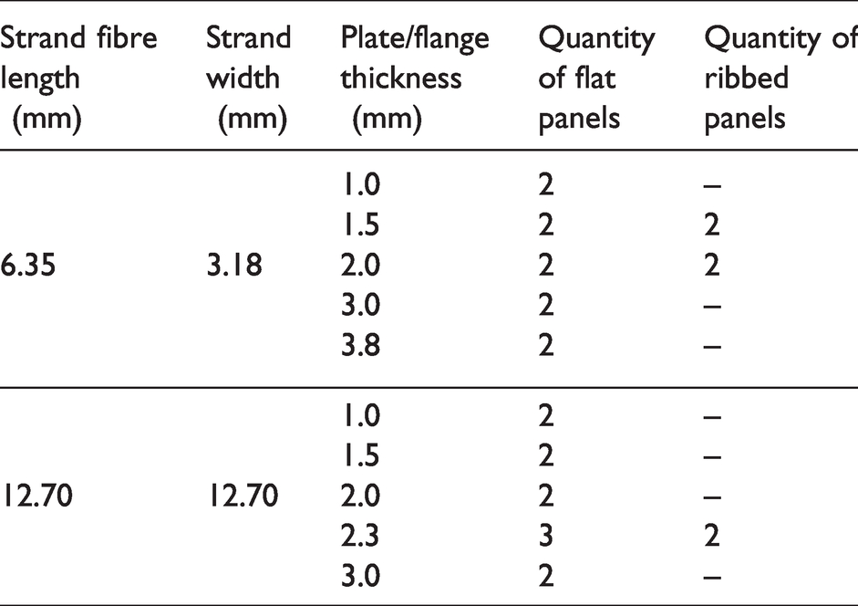
Chopped strands of pre-impregnated unidirectional AS4 carbon fibre/PEEK tape were used to manufacture DLF flat and ribbed panels. Two different sizes of strands were assessed: 1) 6.35 mm long (fibre length) × 3.18 mm wide strands of Toray Cetex® MC1200 bulk moulding compound; and 2) 12.70 mm × 12.70 mm strands of Toray Cetex® TC1200/AS4 tape. The 6.35 mm × 3.18 mm strands will be referred to as “short strands” and the 12.70 mm × 12.70 mm strands will be referred to as “square strands.” Both strand sizes have a fibre volume fraction of approximately 59%, a consolidated ply thickness of 0.132 mm, a melting point of 343°C, and a glass transition temperature of 143°C. Panels were moulded following the test matrix presented in Table 1. Target thickness was achieved by weighing material prior to placement – using the density of the material and the intended volume of the part cavity to determine the required weight. Strands were manually distributed in the mould cavity as shown in Figure 1. To minimize out-of-plane strand orientation, the strands were added in small batches, shuffling between batches to allow for an even and random distribution.
Flat and ribbed panels test matrix.
Processing cycles
To manufacture the flat panels, a picture frame mould was fitted around the bottom platen, creating a 101.6 mm × 101.6 mm mould, and the processing cycle shown in Figure 2(a) was applied. For the ribbed panels, a mould design using 1.0 mm × 3.0 mm ribs was explored, where the ribs were made 50.8 mm apart in both directions, as depicted in Figure 3. The mould was created at an offset such that future work could explore using ribs that are 25.4 mm apart. In other words, the ribs were not centered in the mould but displaced so that if the number of ribs were to be doubled, they would be 25.4 mm apart. A specialized cooling strategy was used based on the findings from Landry and Hubert, 10 to ensure appropriate compaction pressure during crystallization as shown in Figure 2(b). The flange of the part (bottom platen) was kept near molten, with a low modulus, while the ribs (top platen) crystallized, to maintain compaction pressure in the ribs. If the flange solidifies and stiffens before the ribs, the ribs lose pressure and tear away from the mould walls as they cool, leaving a rough, matrix-torn surface. Thus, the ribs needed to be cooled before the flange of the part.
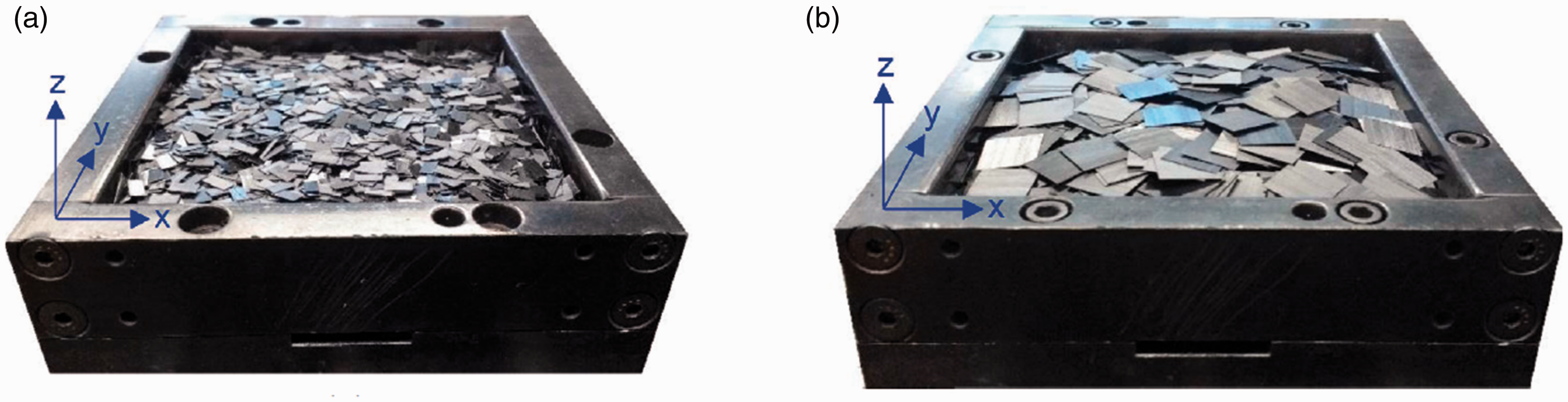
Distribution of (a) small and (b) square strands in the mould cavity.
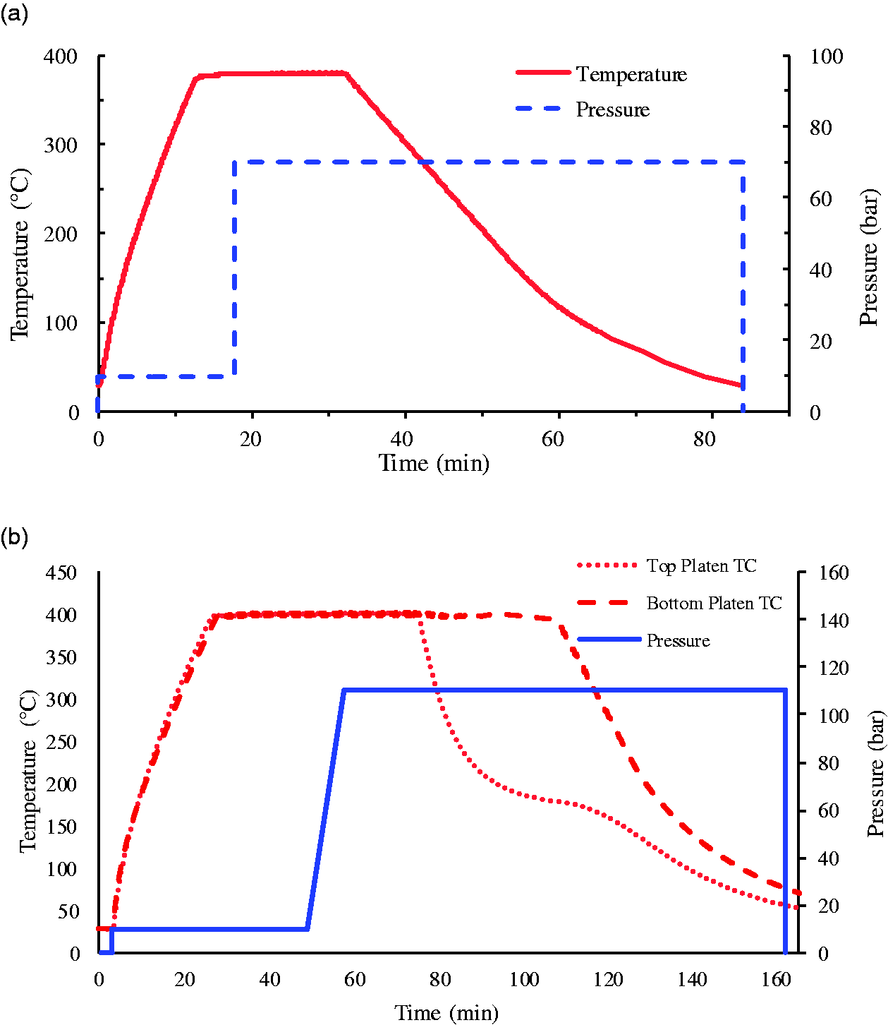
Processing cycle used for the (a) plat panels and (b) ribbed panels.
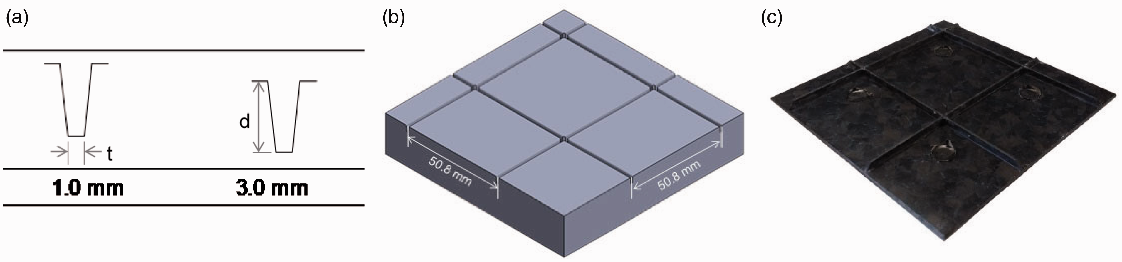
(a) Rib dimensions; (b) Rib placement within the mould; and (c) Moulded part.
Warpage measurements
As the force from a standard dial gauge or CMM probe would deflect the 2.0 mm and thinner panels, they were scanned using a FARO® ScanArm, generating a unique point cloud for each part in Geomagic Studio. The point cloud was then converted to a 3 D model and exported as an STL file. Using InnovMetric’s PolyWorks® IMInspect software, these unique part models were aligned with 3 D models of perfectly flat panels using a best-fit approximation and electronically probed to determine their deviation from a flat surface, effectively providing a flatness measurement. The warpage measurement method is depicted in Figure 4, where the warpage is the shown as the combined delta between the highest and the lowest point from the fitted plane.
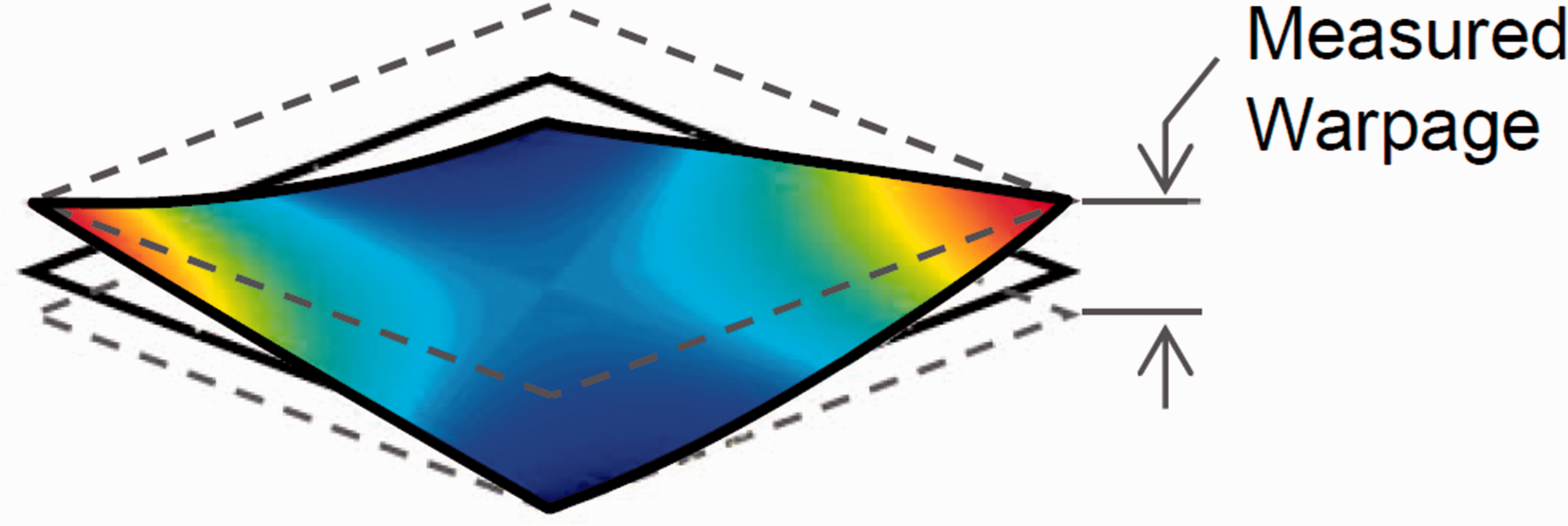
Depiction of warpage measurement for DLF panels.
Results and discussion
Flat panels
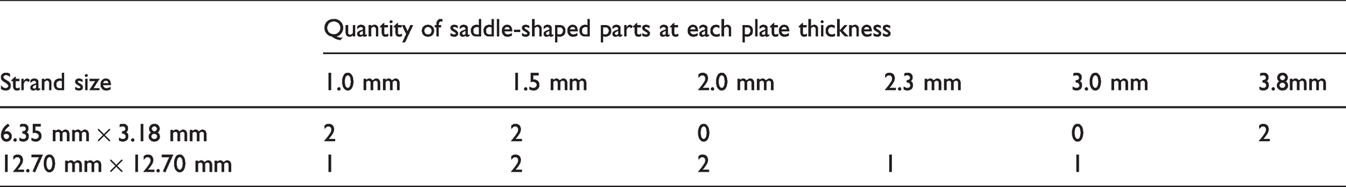
The panels were scanned for warpage assessment. Variation was found in the warped shape, regardless of thickness or strand size. For all parts made, the highest and lowest points on the plate were found along the free edge of the plate, but the locations and number of maxima and minima are not consistent. Of the twenty-one flat panels made, thirteen have relatively saddle-shaped warpage patterns, with saddle points – where orthogonal curves meet at a maximum for one and a minimum for the other – near the centre of the plate. As seen in Figure 5, the saddle shape may have its extrema at all four corners, along each edge, or in some combination of both. The parts that were found to be relatively saddle-shaped are indicated in Table 2, with the quantity of saddle-shaped parts at each strand size and thickness indicated.
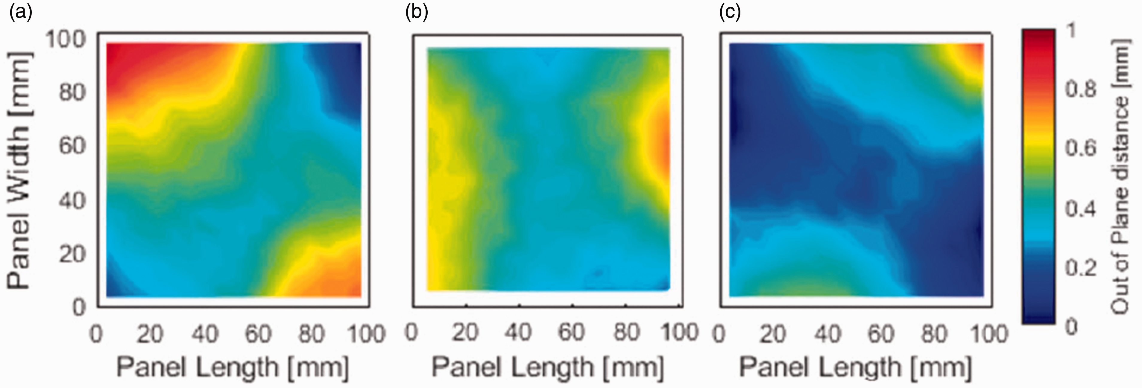
Warped shape of (a) 2.0 mm thick part made with square strands, showing maxima and minima at corners; (b) 1.5 mm thick part made with short strands, showing maxima and minima at free edges; and (c) 2.3 mm thick part made with square strands, showing mixture of maxima and minima at corners and edges.
Distribution of saddle-shaped parts.
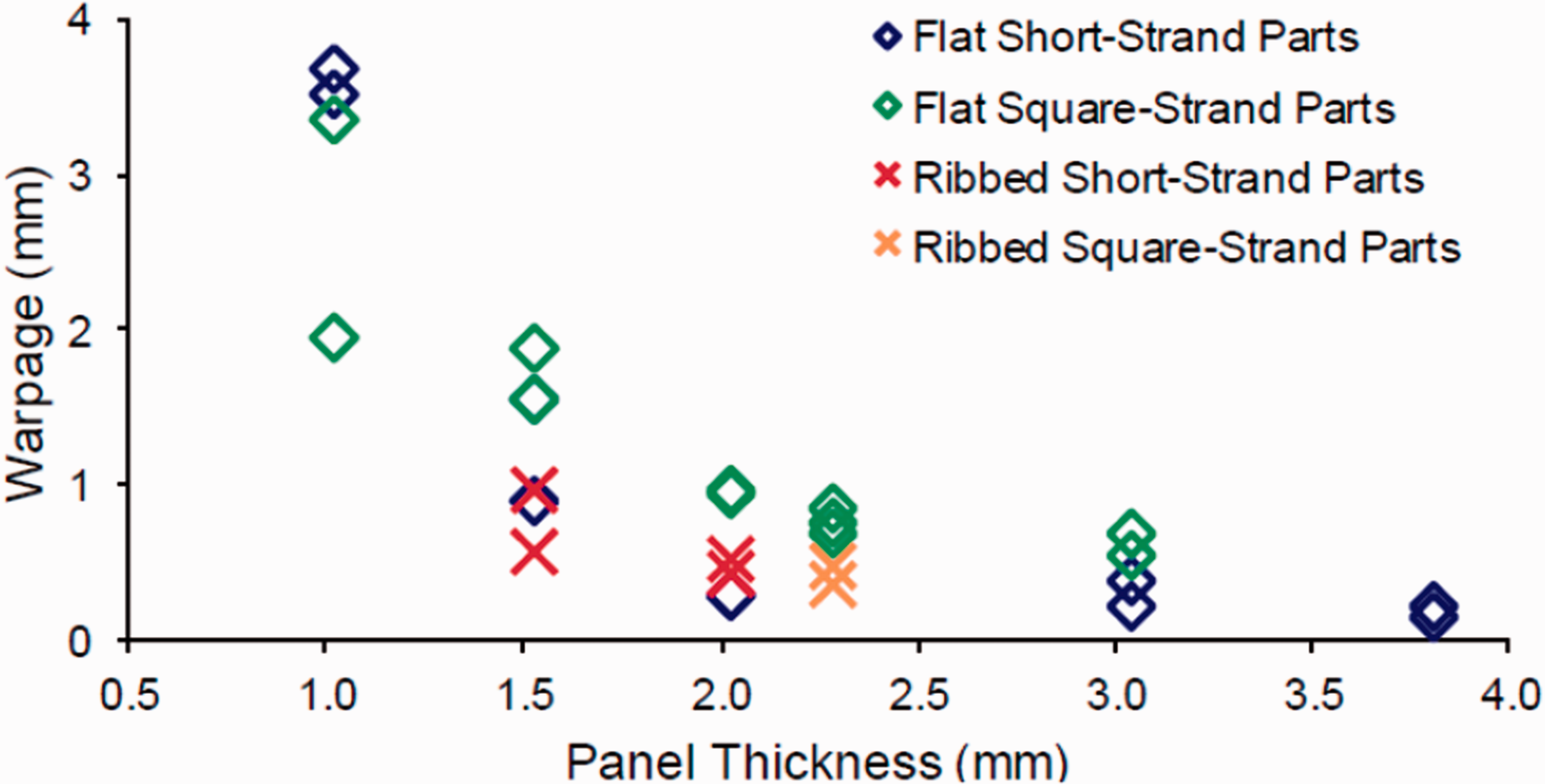
The dependence of warpage on panel thickness obtained experimentally is depicted in Figure 6. From these experimental results, a few trends can be observed. First, there is significant scatter in warpage values for the 1.0 mm and 1.5 mm thick plates. In addition, the warpage values for these plates are greater than the plate thickness. Second, warpage appears to decrease with increasing panel thickness. This trend is intuitive, particularly for thin plates where the temperature gradient through the thickness of the plate is not believed to be significant. As warpage is created by residual stresses internal to the plate, stiffer plates should better resist warpage. The stiffness of the plate is closely tied to its thickness, with its moment of inertia increasing as a cubic function of thickness. Finally, the plates made with the larger, square, strands, sustained greater warpage than those made with the short strands, with the exception of the 1.0 mm thick plates. This trend is less intuitive, but consistent with what was seen by Selezneva and Lessard. 17 Increasing the strand size significantly reduces the number of strands that are randomly distributed within the plate and thus reduce the likelihood of a relatively homogeneous distribution. As the square strands are eight times larger than the short strands, there is roughly one eighth of the number of strands in the same panel thickness, making these panels much more heterogeneous. It is believed that this increased heterogeneity contributes to the increase in part warpage.
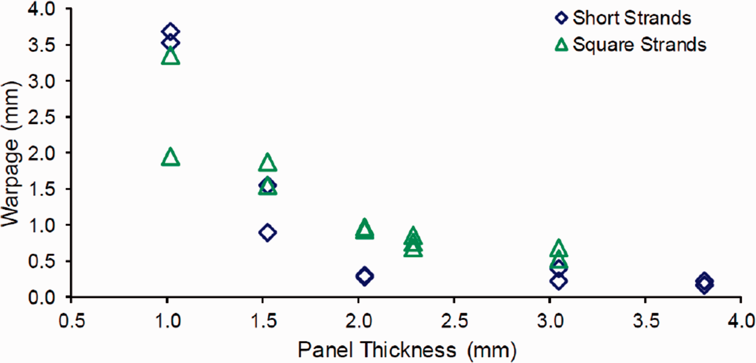
Panel warpage as a function of the thickness.
Ribbed panels
The back surfaces of the ribbed panels were scanned and assessed for warpage. A graph comparing the magnitude of warpage in flat and ribbed panels is shown in Figure 7. The addition of ribs does not have a visibly positive effect on part warpage. The panels made with short strands did not show an improvement in overall magnitude of warpage when compared to flat panels. The magnitude of warpage in the 1.5 mm thick ribbed panels was reduced, but the variation in warpage was still significant. The magnitude of warpage in the 2.0 mm thick ribbed panels was larger than that seen in the 2.0 mm thick flat panels. Minimal reduction in magnitude of warpage was seen when adding ribbing to the 2.3 mm thick plates made of square strands. In addition, the panels made with square strands appear to have warped magnitudes closer to those seen in panels produced with short strands, indicating that the panel ribbing may be influencing warpage more than strand size.
Warpage comparison of flat and ribbed panels.
The addition of ribs did appear to have a positive effect on the consistency of part shape. Unlike the flat panels, where the largest deflections were seen at different points along the part edge, the maximum warpage in all ribbed panels was seen near the centre of the fully supported section. Figure 8 depicts an example of this trend, showing the full panel with the ribs represented as dashed white lines, oriented such that they would be coming out of the page.
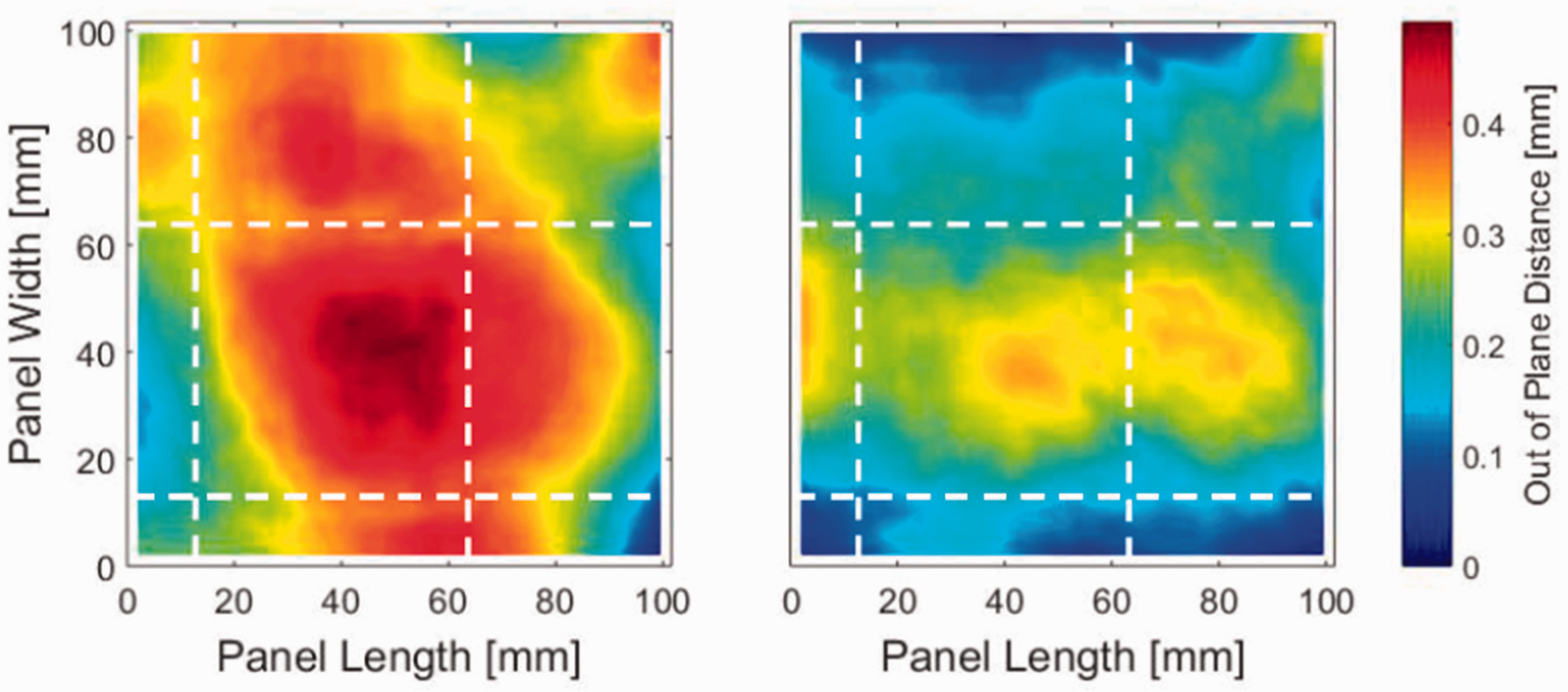
Warpage in ribbed panels made with square strands to be 2.3 mm thick.
This relatively consistent shape appears to come predominantly from the addition of the ribs, particularly since local maxima appear within the sections supported on at least three sides by ribs. Adding ribs changes the dynamic during part cooling as the ribs are cooled before the flange of the part, restricting the in-plane shrinkage of the ribbed surface more than the flat surface. The flat surface experienced more shrinkage, causing the part to bow inwards, between ribbed sections. It is important to note that, because thermal gradient is inherent to the geometry, it is difficult to assess if the presence of ribs could also be contributing to the warping of the part. All ribbed panels produced the same warped shape, creating a dome bowing inwards towards the ribs in each part.
If the fully supported section of the panel is isolated, by looking at data measured for this section, the degree of warpage within this 50.8 mm × 50.8 mm section shows to be consistent in both shape and magnitude. A comparison of the warpage magnitudes between supported sections of the ribbed panels and corresponding sections of the flat panels is captured in Figure 9 to evaluate the effect of the restriction imposed by the ribs on the warpage. For the parts made with short strands, data points for warpage magnitude overlap each other, with a value of 0.15 mm in both 2.0 mm thick parts and a value of 0.25 mm in both 1.5 mm thick parts. By comparing these sections to 50.8 mm × 50.8 mm sections of the flat panels, it is further apparent that the addition of ribs does not lead to reduced magnitude of warpage. In the case of the 2.0 mm thick panels made with 6.35 mm × 3.18 mm strands, the magnitude of warpage was lower in the flat panels than it was in the supported sections of the ribbed panels. It should be noted that, the magnitude of warpage in flat panels made with 6.35 mm × 3.18 mm strands is relatively consistent for parts 2.0 mm thick and thicker. Therefore, this strand size at this thickness is already relatively stable. Adding ribs does not appear to reduce this warpage, but rather creates a new source of warpage.
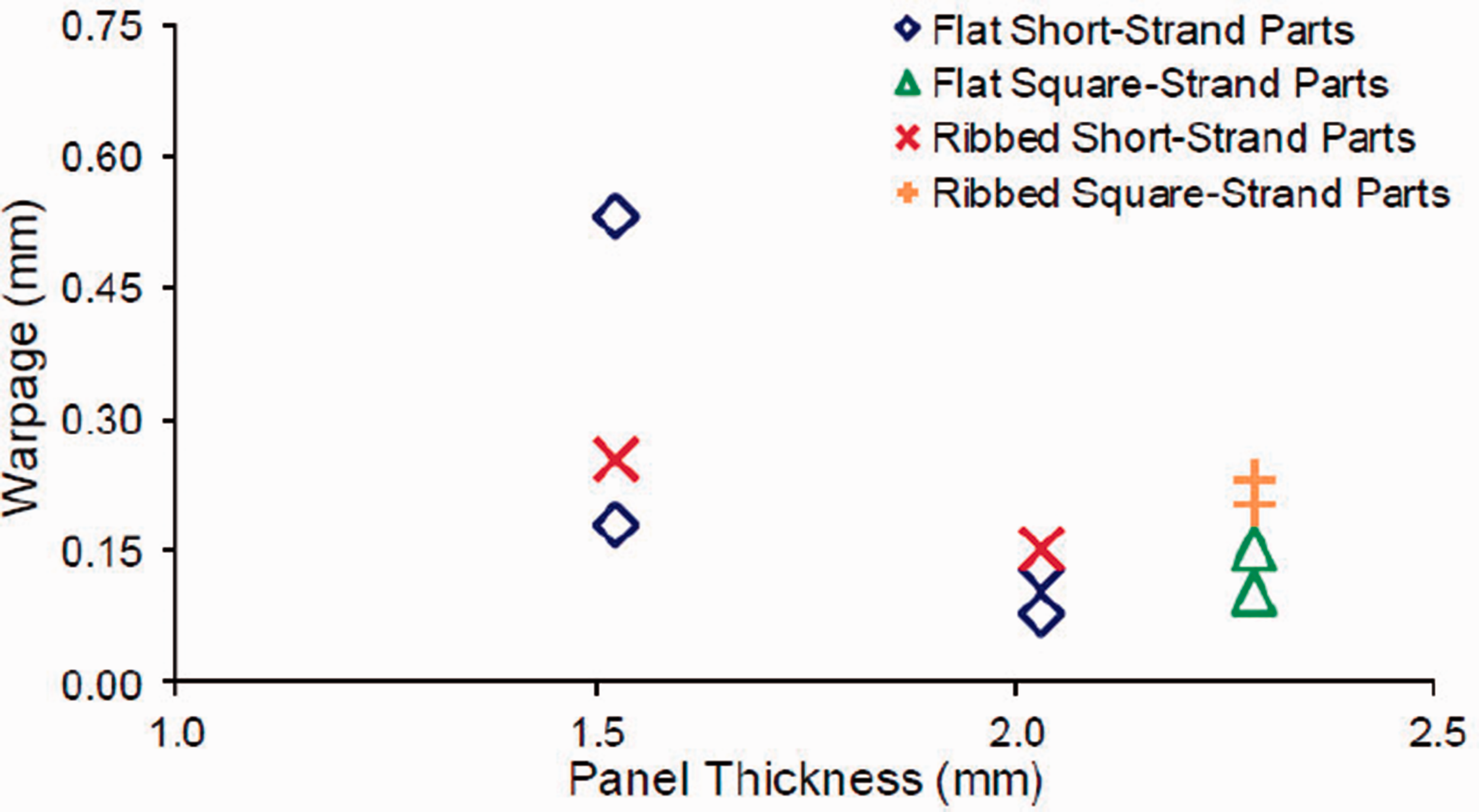
Warpage comparison of 50.8 mm x 50.8 mm supported section of ribbed panels to 50.8 mm x 50.8 mm sections of flat panels at the same part location.
Conclusions
The main objective of this work was to advance the knowledge of warpage in DLF composites such that critical thickness can be determined in the design stages for DLF parts with large, thin sections and tight dimensional stability requirements. In addressing this knowledge gap, processing investigations were performed for thin, flat parts as well as for thin parts with small ribbed features. The following conclusions were drawn:
Flat panels made <2.0 mm thick suffered from the most significant warpage, with significant variation part-to-part. Plates made with short strands warped less than plates made with square strands, leveling out with an average of 0.28 mm warpage for short-strand parts 2.0 mm and thicker, but still showing between 0.53 mm – 0.68 mm in 3.0 mm thick parts made with square strands. Each flat plate warped differently, indicating that the random strand distribution has a dominant effect on part warpage. While many of the parts took on saddle-like shapes, approximately 40% of the parts did not resemble saddles. The addition of evenly spaced, orthogonal rib features altered how the parts warped. Residual stress induced from the ribbed geometry appeared to dominate, reducing the deviation in warpage between parts made with short strands and square strands, but increasing the overall warpage seen in 2.0 mm thick parts made with short strands. However, the shape of the warpage was consistent, particularly within the regions fully surrounded by ribs, the warpage appeared to take on a domed shape, bowing inwards, towards the ribs. Warpage was observed in all the parts, with a significant variation part-to-part. This work contributed by identifying the warpage trends that resulted from each of the changes proposed here (e.g. thickness, strand size, addition of ribs). However, a greater number of samples would be beneficial to provide a better statistical data and to assist in future warpage prediction.
Footnotes
Acknowledgments
The authors would like to thank the financial support provided by the Consortium for Aerospace Research and Innovation in Canada (CARIC), the Consortium for Research and Innovation in Aerospace in Quebec (CRIAQ) and industrial partners: Pratt and Whitey Canada Corp., Hutchinson Aerospace & Industry Ltd, and Dema Aeronautics. Acknowledgments also go to the Research Centre for High Performance Polymer and Composite Systems (CREPEC) for their support.
Declaration of Conflicting Interests
The author(s) declared no potential conflicts of interest with respect to the research, authorship, and/or publication of this article.
Funding
The author(s) received no financial support for the research, authorship, and/or publication of this article.