
Abstract
In this study, silicate- based 13-93 bioactive glass (BG) /poly-ε-caprolactone (PCL) nanocomposite fiber mats were fabricated through electrospinning. To prepare composites, amorphous electrospun bioactive glass nanofibers (BGFs) or melt-derived microscale bioactive glass particles (BGPs) were incorporated into the PCL matrix. In vitro mineralization ability of the prepared fibrous mats was assessed in simulated body fluid under static conditions. The results revealed that it is possible to prepare bead-free continuous nanofibers using PCL-acetone solution at specified PCL concentrations (8 and 10 wt%). Nanofibers with almost uniform diameters were produced using 10 wt% PCL solution. Incorporation of BG in the form of particle or fiber into the PCL matrix was made between 1 wt% and 10 wt%. The results showed that the diameter of BGP-containing composite fibers was higher compared to BGF-containing composite scaffolds. The addition of BG to the PCL matrix both in the form of powder and fiber enhanced hydroxyapatite formation in the fibrous scaffolds. The amount of calcium phosphate–based material formation was higher in glass particle–containing samples compared to glass fiber–containing PCL scaffolds. Additionally, the degradation rate in phosphate buffer and silicium ion release amount of BGP-containing PCL fibers was higher compared to BGF-containing PCL fibers. It was concluded that fibrous composite scaffolds prepared in this study could have potential in tissue engineering applications.
Introduction
Fibrous scaffolds consisting of nanofibers have gained increasing attention in tissue engineering applications. These structures have morphologies and fiber diameters in a range comparable with those found in the extracellular matrix of human tissues. They support cell expansion and differentiation and can be employed as a vehicle for cell transplantation to the damaged tissue. They can also be utilized in wound healing and drug delivery applications. 1 –4 One of the approaches used in the manufacture of nanofibrous scaffolds is electrospinning. 1,2
Poly-ε-caprolactone (PCL) is a biodegradable polymer with high toughness and good biocompatibility. 5 It is a semicrystalline aliphatic polymer that has a slower degradation rate than most biocompatible polymers. 6,7 PCL has limitations in bone regeneration applications because of its low stiffness, hydrophobic nature, and lack of bioactivity. 7,8 The combination of PCL and other biopolymers with bioactive materials such as hydroxyapatite (HA) and bioactive glass (BG) is a promising way to overcome these drawbacks. 8 –13
BGs are surface reactive materials used for bone and soft tissue repair. They are reported to be able to stimulate bone regeneration more than other bioactive ceramics. 14 –16 The silicate-based 13-93 BG composition (in mol%: 54.6% silicon dioxide (SiO2), 22.1% calcium oxide (CaO), 7.9% potassium oxide (K2O), 7.7% magnesium oxide (MgO), 6.0% sodium oxide (Na2O), and 1.7% phosphorus pentoxide (P2O5)) was approved by the US Food and Drug Administration. 17,18 It has the capacity to support cell proliferation and the ability to be formed into porous scaffolds by viscous flow sintering. 18
Ahmed et al. 9 fabricated the composites of PCL and phosphate-based bioglass fibers using compression molding. The modulus increased from 0.5 GPa for pure PCL to approximately 2.5 GPa for composite film containing 18 vol.% bioactive glass fiber (BGF). The degradation rate of composites also increased by increasing glass fiber content. 9 Kouhi et al. 8 fabricated BG-containing PCL nanofibers using electrospinning method. Evaluation of the mechanical properties revealed that there is a limit to the nanoparticle concentration at which BG nanoparticles can improve the tensile strength of the PCL nanofibrous web. The X-ray diffraction (XRD) analysis indicated that an HA layer formed on the surface of the nanofibrous samples after soaking in simulated body fluid (SBF) over different time periods. 8 Similarly, Otadi and Mohebbi-Kalhori 19 produced PCL-BG nanocomposites using electrospinning method. In addition to 45S5 BG, sol-gel derived BGs (based on SiO2-CaO- SrO-P2O5) were used in the system having different SrO content. The results revealed that bioactive glass particles (BGPs) with good dispersion and distribution in the nanofibers increase mechanical properties compared with pure PCL, but the 45S5 makes the nanocomposite structure more fragile. 19 Previous studies also showed that the electrospun nanocomposites of PCL scaffolds incorporating the BG have excellent performance in cell attachment and proliferation for bone remodeling. 6 More recently, Lepry et al. 20 studied the fabrication and acellular bioactivity of sol–gel-derived borate glass-PCL electrospun scaffolds. Scanning electron microscopy (SEM), Fourier-transform infrared (FTIR) spectroscopy, and XRD analysis indicated apatite formation in the BG (5 w/v%) incorporated composite scaffold, which initiated after 3 days of immersion in SBF. 20
Although the preparation of BG-PCL composites had been studied previously, the use of 13-93 glass in this system and the effect of 13-93 BG morphology on the in vitro mineralization behavior of electrospun BG-PCL scaffolds were not investigated yet to the best of our knowledge. Therefore, the aim of this work was to prepare 13-93 BG-PCL composite nanofibrous scaffolds and to investigate the effect of BG morphology (particulate or fiber) on the HA formation ability and degradation behavior of these scaffolds. For this purpose, PCL nanofibers containing 13-93 bioactive glass nanofibers (BGFs) or 13-93 powders (BGP) were prepared through electrospinning technique. Characterizations were performed to investigate the morphology, in vitro mineralization, and degradation behavior of these composite electrospun fibers in physiological fluids.
Materials and methods
Materials
PCL (Aldrich 440744, Mn : 80,000 g/mole) was purchased from Aldrich. Acetone (Sigma-Aldrich, St.Louis, USA) was used as received. Amorphous silicate–based 13-93 (in mol%: 54.6% SiO2, 22.1% CaO, 7.9% K2O, 7.7% MgO, 6.0% Na2O, and 1.7% P2O5) BGFs that were prepared previously by electrospinning technique and calcined at 625°C were utilized in the study by Deliormanlı. 21 They were ground into short fibers using an agate mortar prior to experiments.
Bioactive glass particles
The silicate-based 13-93 glass particles, used in this study, were prepared by melt-cast method. For this purpose, a homogeneous mixture of reagent-grade chemicals of CaCO3, Na2CO3, MgCO3, K2CO3, SiO2, and CaHPO4·2H2O (Fisher Scientific, St. Louis, Missouri, USA) particles (in appropriate quantities) was melted in a platinum crucible in air atmosphere for 2 h at 1350°C, and molten glass was quenched between steel plates. Then, they were ground using a planetary micro mill (Fritsch Pulverisette 7, premium line, Idar-Oberstein, Germany) for size reduction and sieved to a size of <106 µm.
PCL solution preparation and electrospinning
In the study, acetone was utilized in solution preparation because it is a readily available and nontoxic solvent. PCL solutions (8, 10, 12, and 14 wt%) were prepared by dissolving an appropriate amount of PCL pellets in anhydrous acetone by stirring at 50°C for 2 h. The 1, 5, or 10 wt% 13-93 BGFs being ground into short fibers or 13-93 glass particles (BGP) were then incorporated into the PCL organic matrix solution at 50°C and homogenized using a magnetic stirrer for 20 min, followed by homogenization using an ultrasonic horn for an additional 10 min. Then, 10 ml of this solution mixture was immediately loaded to a syringe and the syringe was placed on a micropump. From the syringe, solution was fed to a metallic nozzle at a rate of 0.5 ml h−1. During electrospinning experiments, a laboratory scale nanospinner (NE-300; Inovenso, Istanbul, Turkey) was utilized. The setup includes a nozzle system that delivers polymer solution, grounded collector, and a high-voltage electric field between the collector and the nozzle. When the voltage is high enough to overcome the surface tension of the polymer solution, a charged jet is generated toward the grounded collector, along which the solvent evaporates from fibers. A grounded stainless steel cylinder was utilized as the collector. The experiments were carried out by maintaining a distance of 15 cm between the tip of the nozzle and the rotating collector. An electrical voltage of 25 kV was applied to the metallic nozzle delivering the polymer solution by a high-voltage power supply. Experiments were performed at room temperature (25°C) in a closed chamber.
Characterizations
BGPs and BGFs
Median diameter of the glass particles after size reduction and the BGFs after being ground into short fibers was measured using a laser diffraction particle size analyser (Malvern Mastersizer 3000, UK). The device uses Mie theory of light scattering to calculate the particle size. XRD (Philips, X’Pert Pro, Eindhoven, Netherlands) was used to analyze the presence of any crystalline phase formation in 13-93 BGPs and BGFs; XRD was performed using copper Kα radiation at a scanning rate of 0.01° min−1 in the 2θ range of 10–90°.
Viscosity measurements
Apparent viscosity of the PCL-acetone solutions in the absence and presence of BGF and BGP was measured using a controlled rate rotational viscometer (HAAKE Viscotester E; HAAKE Inc., Paramus, New Jersey, USA) with a small sample adaptor. Measurements were performed with TR series spindles, using 8–13 ml of suspension. Variation in shear stress and the viscosity of polymer solutions were monitored as a function of shear rate. All measurements were performed at 25°C in the presence of a circulating water bath. A specially designed solvent trap was utilized during the measurements to eliminate the solvent evaporation.
Morphology of the composite fibers
After electrospinning, fabricated PCL fiber composite scaffolds were dried at room temperature at least for 48 h prior to characterizations. The morphology of the as-prepared and SBF-treated fibers was examined using SEM (Philips XL-30S FEG, Netherlands) at an accelerating voltage of 5 kV and a working distance of 10 mm. About 40 randomly selected fibers taken from the SEM micrographs were utilized to obtain the fiber diameter distribution and determine the average fiber diameter.
In vitro bioactivity and degradation
The bioactivity of scaffolds was investigated in vitro in SBF under static conditions. SBF was prepared in compliance with the protocol of Kokubo et al., 22 by dissolving reagent-grade chemicals of NaCl, NaHCO3, KCl, K2HPO4·3H2O, MgCl2·6H2O, CaCl2, and Na2SO4 (Sigma-Aldrich, Germany) in deionized water and buffering at a pH of 7.40 with ((CH2OH)3CNH2) and 1 M hydrochloric acid (Fisher Scientific Inc.). Ratios of 1 g of sample to 1000 ml of SBF were used in the conversion experiments. Each sample was immersed in a polyethylene bottle containing the SBF solution and kept for varying time periods, without shaking, in an incubator at 37°C. After removal from SBF, the samples were first rinsed with deionized water and then with ethanol and dried at room temperature prior to characterizations. Ultrapure water with a resistivity of 18 MΩ·cm was used through the experiments.
SEM was utilized to analyze the structure of reacted composite scaffolds, using the conditions described previously. Attenuated total reflectance–Fourier-transform infrared (FTIR-ATR; Agilent Cary 660, USA) was also used to characterize HA-like layer formed on the surfaces of composite scaffolds. FTIR analysis was performed in the wave number range of 400–4000 cm−1. Atomic force microscopy (Ambios Q250, Russia) was utilized to analyze the surface roughness of SBF-treated composites. Additionally, in SBF solutions, silicium concentration was measured using ICP-OES (Optima 8000, PerkinElmer) to analyze the Si ion released from composite fibers.
In the study, degradation (weight loss) of the prepared fibrous scaffolds was analyzed in phosphate buffer solution (initial pH 7.4) at 37°C for 30 days. The degree of degradation may be estimated from measurements of mass loss. The percentage of weight loss, W%, is computed from

where W 0 is the initial mass of the scaffold and Wf is the final mass.
Results and discussion
The morphology of the synthesized BGPs and BGFs utilized in the study is shown in Figure 1(a) and (b). SEM micrographs revealed that the sintered glass fibers have well-defined fibrous structure and BGPs showed an irregular morphology. Figure 1(c) and (d) shows the particle size and fiber diameter distribution of 13-93 BG powders and fibers. Median particle size of the glass powders was measured to be 2.3 µm, whereas average fiber diameter was calculated to be 508 ± 88 nm. Figure 1(e) shows the particle size analysis graph of 13-93 fibers after being chopped (using an agate mortar) into short fibers. High median diameter and bimodal size distribution reveal that 13-93 fiber mats tend to form an agglomerated network of short fibers after chopping and they have a high aspect ratio.
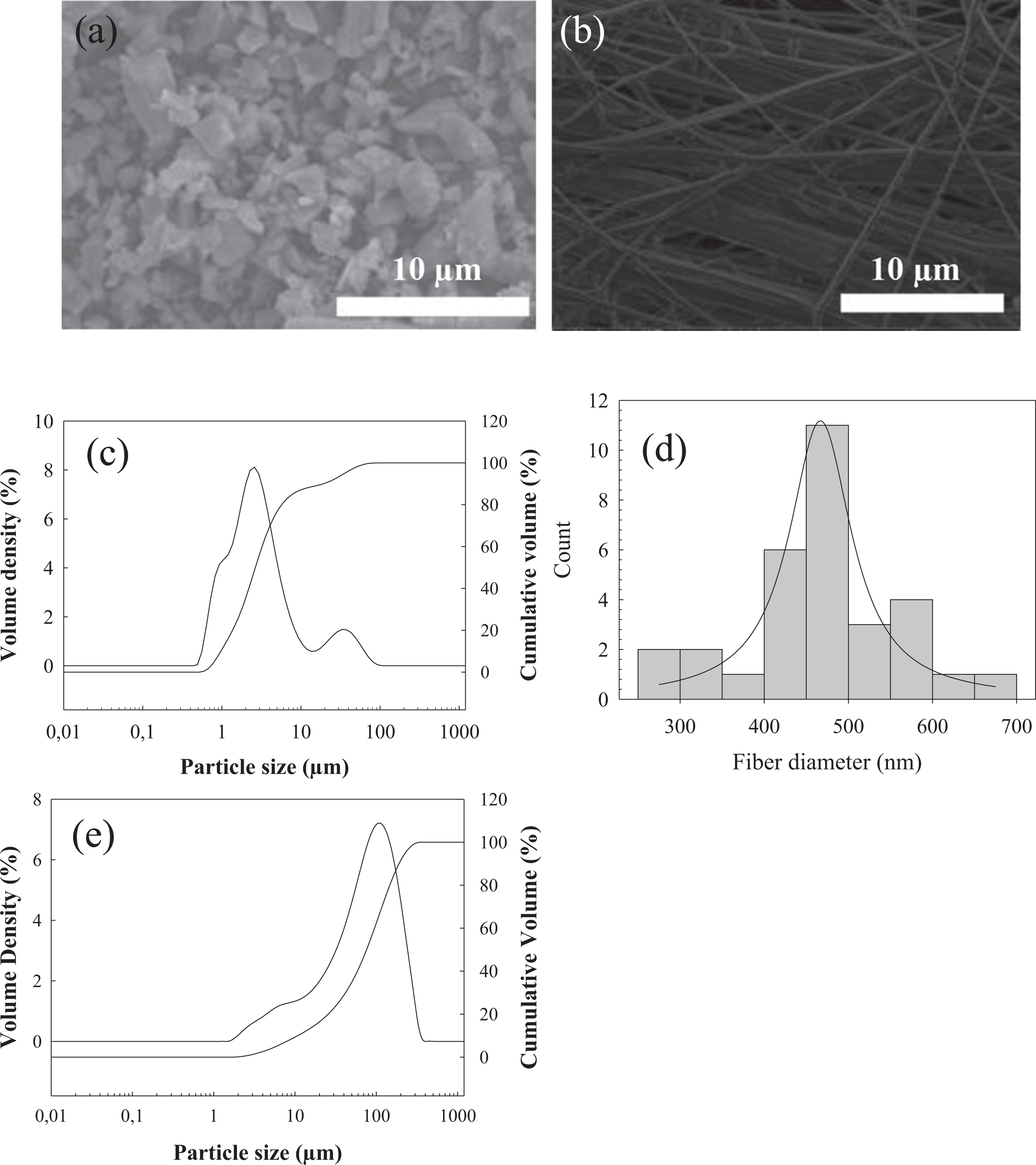
SEM micrographs of the 13-93 bioactive glass (a) particles and (b) fibers utilized in the study, (c) particle size analysis graph for 13-93 particles, (d) fiber diameter distribution of the bioactive glass 13-93 fibers, (e) particle size analysis graph for 13-93 fibers after being ground into short fibers. SEM: scanning electron microscopy.
Figure 2 shows the XRD diagrams of the 13-93 glass fibers and particles utilized in the study. Accordingly, both in electrospun fibers and in melt-derived 13-93 BGPs, any crystalline phase formation was not observed and they showed amorphous structure.
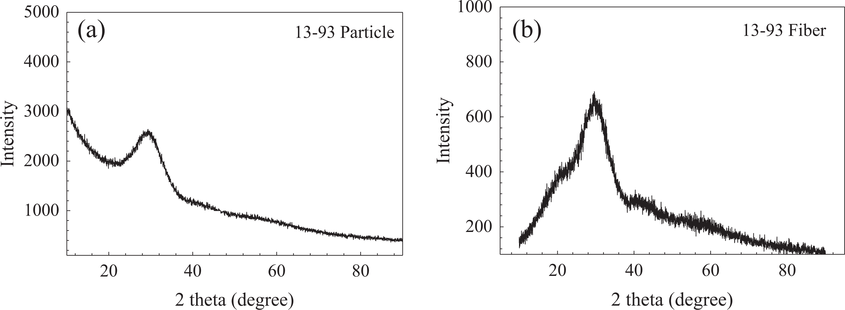
XRD diagrams of the (a) melt-derived bioactive glass particles and (b) electrospun bioactive glass fibers used in the study. XRD: X-ray diffraction.
PCL solution properties
Viscosity of the pure PCL solutions in the absence and presence of BG was measured and their flow behavior was investigated. Figure 3(a) and (b) shows the shear stress versus shear rate and viscosity versus shear rate graphs for PCL-acetone solutions at different concentrations. Accordingly, an increase was observed in solution shear stress and in viscosity as the PCL concentration was increased, and all of the PCL solutions tested showed Newtonian flow behavior. Viscosity of the pure PCL solution (10 wt%) was measured (shear rate: 35 1/s) to be 160 mPa. On the other hand, apparent viscosity values of the BGP and BGF-containing (at 10 wt%) PCL solutions were measured to be 220 and 180 mPa, respectively, under the same conditions (Figure 3 [c]).
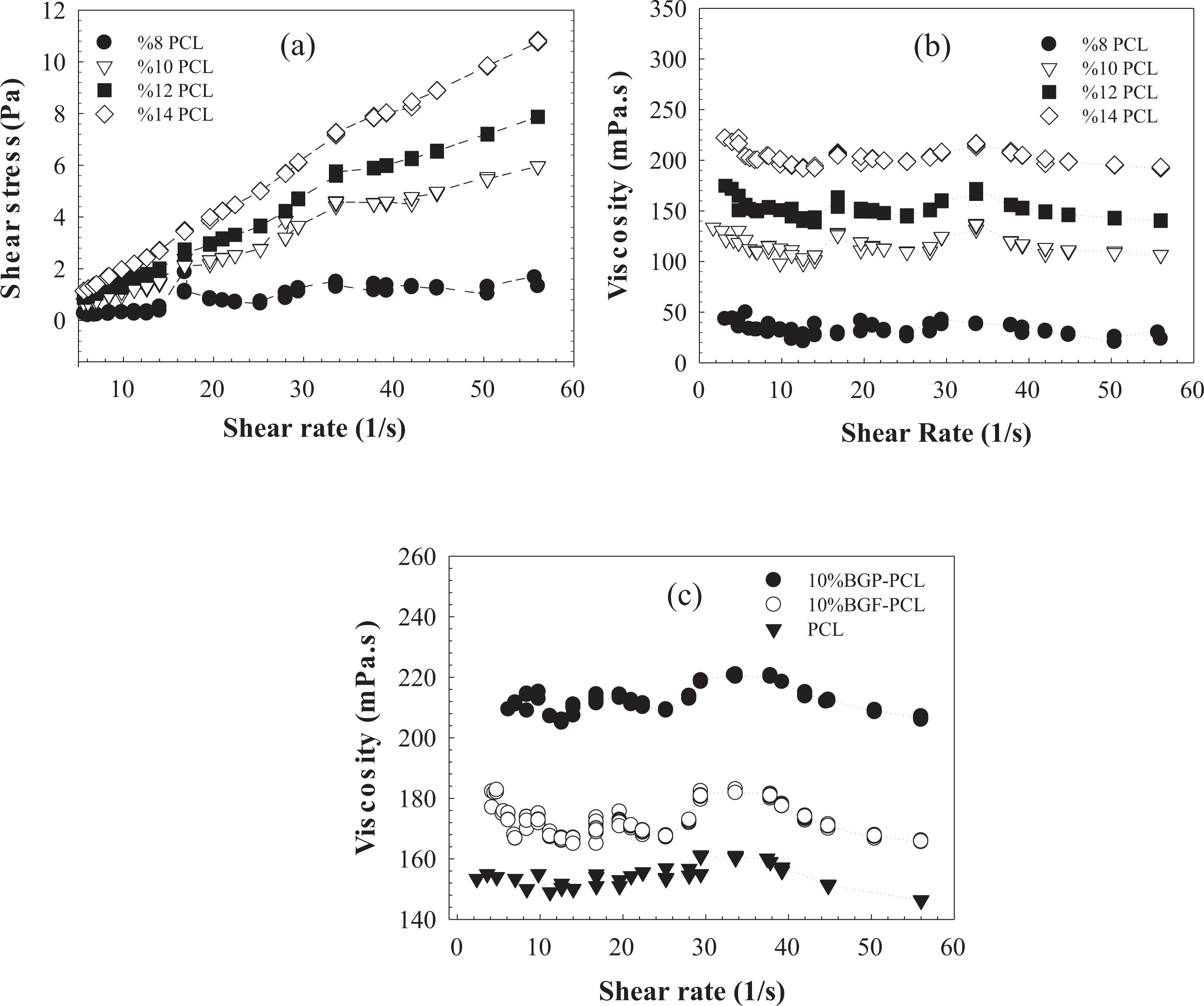
(a) Shear stress versus shear rate, (b) viscosity versus shear rate graph for PCL solutions at different concentrations, and (c) viscosity of bioactive glass (10 wt%)-containing PCL solutions (10 wt%) as a function of shear rate. PCL: poly-ε-caprolactone.
Viscosity of a polymer solution generally increases with the increase in concentration. There are four regimes for polymer solutions: dilute, semidilute unentangled, semidilute entangled, and concentrated. The transition between dilute and semidilute unentangled regimes occurs at a concentration known as overlap concentration. At this concentration, the individual chains begin to overlap with one another but still remain largely unentangled. The transition between semidilute unentangled and semidilute entangled regimes is known as entanglement concentration (Ce). It is known that a concentration ≥Ce is required to get a stable electrospinning and uniform beadless fibers. 23 Ce of PCL-acetone solution used in this study may be lower than 8 wt% because no bead formation was observed at this concentration and it was possible to obtain continuous fiber network.
Electrospun PCL fibers
Fiber morphology of the bare and BG-containing electrospun PCL samples was investigated using SEM. During spinning, no bead formation was observed in the fibrous mats, and nanofibers deposited randomly in the form of a thin sheet on the counter electrode for PCL solutions prepared at 8 wt% and 10 wt% (Figure 4). Starting from 12 wt%, an increase was observed in fiber diameter and at 14% PCL concentration fibrous network formation disrupted. At PCL concentration of 14%, spinning was found to be difficult presumably due to rapid drying of the solution at the nozzle tip. For the four concentrations investigated, the lower two concentrations (8 and 10 wt%) resulted in the production of submicron fibers, whereas micron-sized fibers were most common for 12 and 14 wt% solutions. The average fiber diameter was measured to be 314 ± 210 nm, 450 ± 80 nm, 1658.9 ± 598 nm, and 3327 ± 740 nm for PCL solutions at 8 wt%, 10 wt%, 12 wt%, and 14wt% PCL, respectively (Figure 4(e)). Compared with the other concentrations, the SEM micrograph of the fibers prepared using 10 wt% PCL shows a narrower fiber diameter distribution. Therefore, based on the SEM analysis, optimum PCL concentration was chosen at 10 wt% to carry out the subsequent electrospinning experiments in the presence of BG.
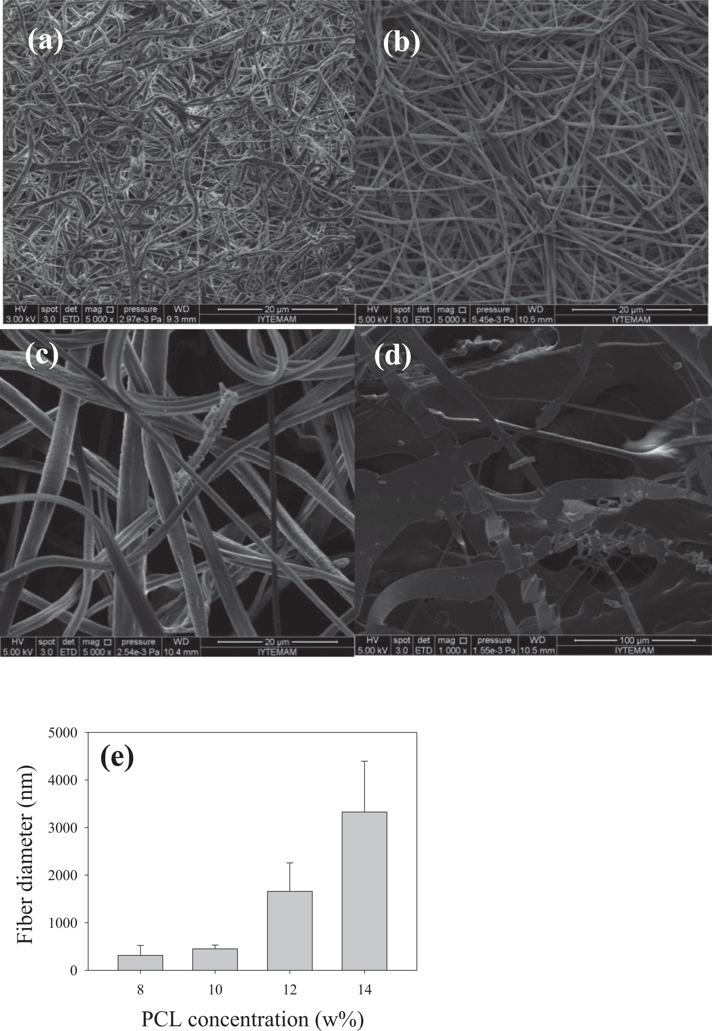
SEM micrographs of the electrospun PCL fibers prepared at different PCL concentrations (a) 8 wt%, (b) 10 wt%, (c) 12 wt%, (d) 14 wt%, and (e) fiber diameter distribution of the electrospun PCL fibers prepared at different concentrations. SEM: scanning electron microscopy; PCL: poly-ε-caprolactone.
In the study, 13-93 BG in the form of fibers or powders (at 1, 5, and 10 wt%) was successfully incorporated into the PCL matrix through the electrospinning process. An increase was observed in PCL fiber diameter by the addition of the BG phase to the matrix system both in the form of particle and fiber. The increase mainly occurred in regions containing BGPs, with the diameters of glass-free regions in the composite scaffolds exhibiting dimensions comparable to those of bare PCL fibers. The presence of glass particles or glass fibers did not result in apparent fiber discontinuities in the composites. Fiber diameter distribution graphs of the BG/PCL composite fibers are shown in Figure 5. Accordingly, PCL/glass composite fiber diameter was measured to be 503.9 ± 108 nm and 518.4 ± 149 nm when the 13-93 BG (at 1 wt%) was incorporated in the form of particle and fiber, respectively. Fiber diameter of BGP-PCL fibrous scaffolds reached to 761.2 ± 296 nm when glass was added at 10 wt%. Diameter of the BGF-PCL fibers was measured to be 647.34 ± 296 nm under the same conditions. Fiber diameters in the range of a few micrometers to hundreds of nanometers may be preferred for bone tissue regeneration due to the closer similarity in size with collagen fibrils naturally present in bone tissue. 24
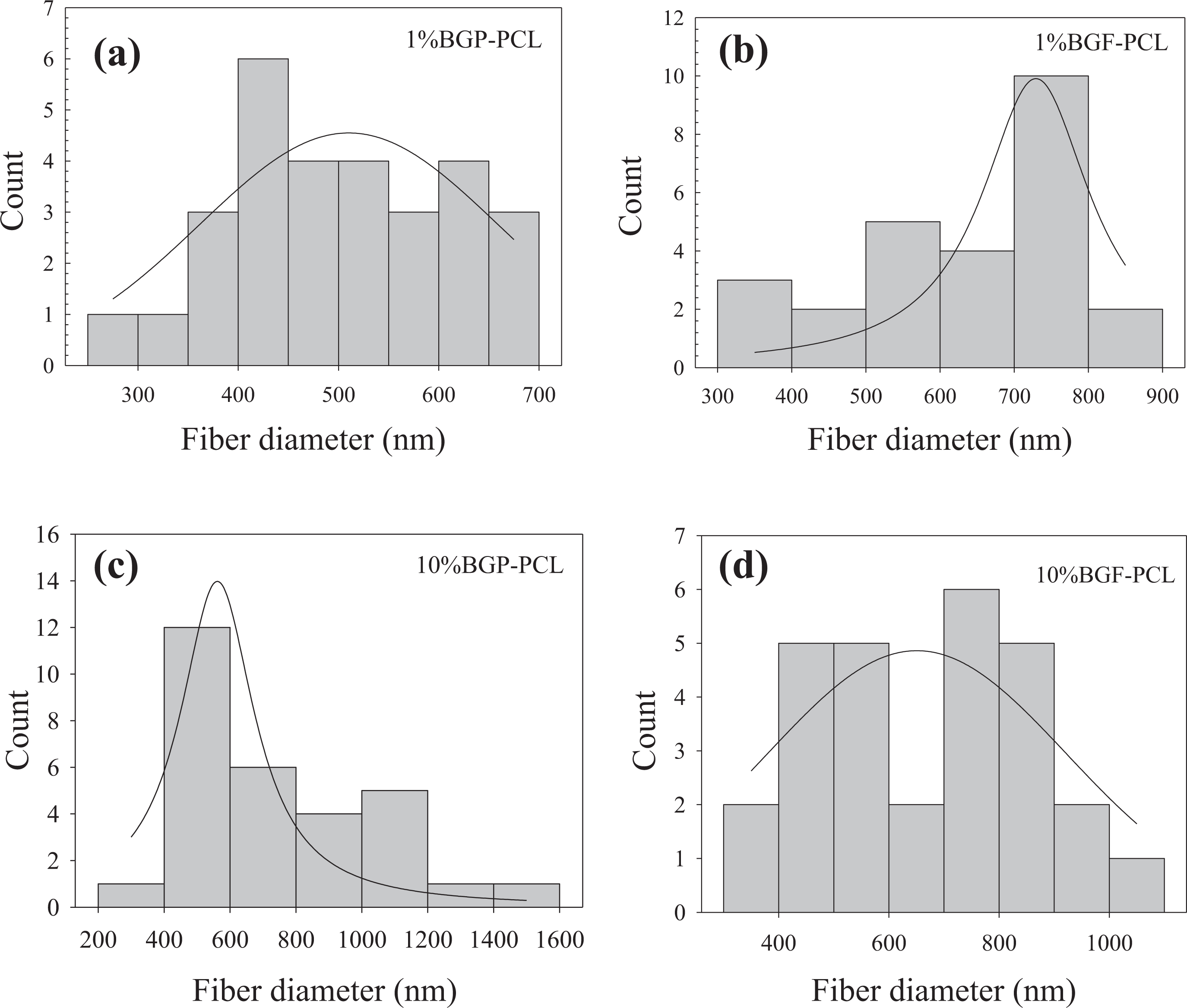
Fiber diameter distribution of the electrospun PCL-bioactive glass composite fibers prepared in the study: (a) and (c) BGP-PCL and (b) and (d) BGF-PCL. BGF: bioactive glass fiber; BGP: bioactive glass particle; PCL: poly-ε-caprolactone.
In vitro bioactivity
In the study, HA forming ability of the PCL-BG composite scaffolds was investigated in SBF at 37°C. Figures 6 and 7 show the surface morphology of BGF-PCL and BGP-PCL scaffolds, respectively, after immersion in SBF for 7 days. Accordingly, a second-phase material presumably an amorphous calcium phosphate or HA was observed in both glass fiber and glass particle–containing PCL scaffolds. The amount of this second-phase material was higher in composite samples containing higher concentration of BG. SEM micrographs of the pure PCL, 10% BGP-PCL, and 10% BGF-PCL composite fibers treated in SBF for 30 days are shown in Figure 8. HA-like layer formation has been clearly observed in 10% BGP-PCL scaffolds. The converted layer on the BGP-PCL composite fibers consisted of fine, plate-like particles, typically observed for nanocrystalline HA formed by conversion of reacting silicate BGs in an aqueous phosphate solution. 25
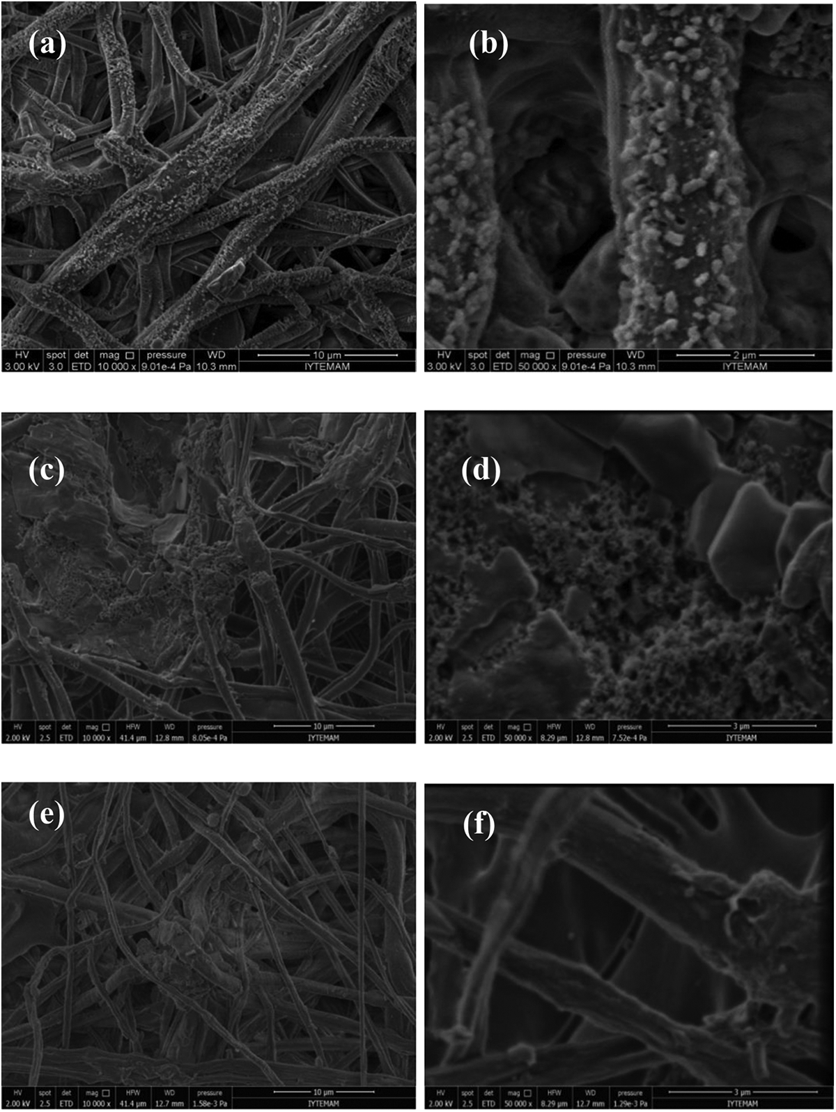
SEM micrographs of the PCL-bioactive glass composite fibers treated in SBF for 7 days: (a) and (b) 1% BGF-PCL, (c) and (d) 5% BGF-PCL, and (e) and (f) 10% BGF-PCL, scale bar (left): 10 micrometer, scale bar (right): 2 micrometer. SEM: scanning electron microscopy; PCL: poly-ε-caprolactone; SBF: simulated body fluid; BGF: bioactive glass fiber.
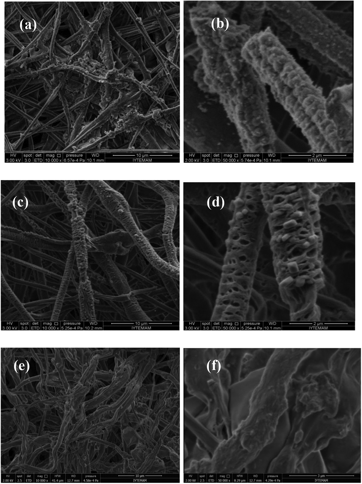
SEM micrographs of the PCL-bioactive glass composite fibers treated in SBF for 7 days: (a) and (b) 1% BGP-PCL, (c) and (d) 5% BGP-PCL, and (e) and (f) 10% BGP-PCL, scale bar (left): 10 micrometer, scale bar (right): 2 micrometer. SEM: scanning electron microscopy; PCL: poly-ε-caprolactone; SBF: simulated body fluid; BGP: bioactive glass particle.
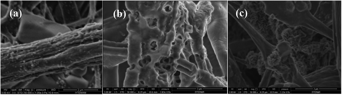
SEM micrographs of the PCL-bioactive glass composite fibers treated in SBF for 30 days: (a) pure PCL, (b) 10% BGF-PCL, and (c) 10% BGP-PCL, scale bar: 2 micrometer. SEM: scanning electron microscopy; PCL: poly-ε-caprolactone; SBF: simulated body fluid; BGF: bioactive glass fiber; BGP: bioactive glass particle.
Calcium phosphate–based material formation was also analyzed by ATR-FTIR spectroscopy. FTIR spectra of untreated pure PCL fibers (Figure 9(a)) showed bands associated with the crystalline phase at 1295 cm−1 and amorphous phase at 1166 cm−1. The band at 1721 cm−1 can be attributed to the stretching of s(C=O), while the bands at 1237 and 1180 cm−1 represent the asymmetrical stretching of as(C–O–C) and symmetric stretching of ss(C–O–C), respectively. 27,26 Additionally, the asymmetric CH2 stretching at 2943 cm−1 and symmetric CH2 stretching at 2866 cm−1 that were the characteristic peaks of PCL were also observed on the samples. 27
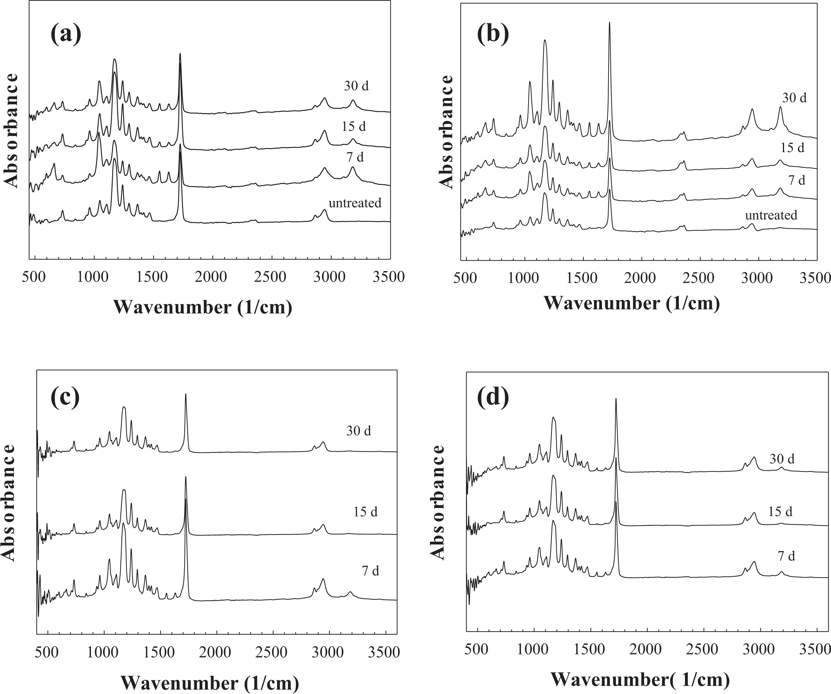
FTIR spectra of the PCL-bioactive glass composite fibers treated in SBF for different time intervals: (a) PCL, (b) 1% BGF-PCL, (c) 5% BGF-PCL, and (d) 10%BGF-PCL. FTIR: Fourier-transform infrared; SBF: simulated body fluid; PCL: poly-ε-caprolactone; BGF: bioactive glass fiber.
FTIR spectroscopy analysis of the SBF-treated composite fibers showed resonances at 1000–1100 cm−1 and at 570 cm−1 corresponding to a calcium phosphate (Figures 9 and 10). The two P–O bending peaks at 560 and 604 cm−1 are the main peaks for characterizing the HA formation. 28,29 A crystalline Ca-P layer, as indicated by the divided P–O bending vibration band between 550 cm−1 and 610 cm−1, formed only in BGP-containing samples immersed in SBF. The results also revealed that a crystalline Ca-P layer, as indicated by the divided P–O bending vibration band, appeared after only 15 days of immersion or longer (30 days) in 5% BGP-PCL and 10% BGP-PCL samples. Higher intensity in P–O bending peaks in these samples suggests a faster HA formation rate. Additionally, the broadening of the peak around 1020 cm−1 was observed in all BGP-PCL samples. The peak broadening started from 15 days of immersion for 1% BGP-PCL, whereas for 5% BGP-PCL and 10% BGP-PCL samples, it was noticeable starting from 7 days of immersion. Especially for the sample 5% BGP-PCL immersed in SBF, the broadening of the peak around pronounced by day 30, surpassing the intensity of the characteristic PCL _s(C=O) peak at 1721 cm−1. The time in SBF indicated the progressive increase in the intensity of the peak around 1020 cm−1, which is attributed to PO3 −4 demonstrating calcium phosphate formation. In contrast, the spectra for the bare PCL and the BGF-PCL samples treated in SBF remained largely unchanged as a function of time in SBF (Figure 10).
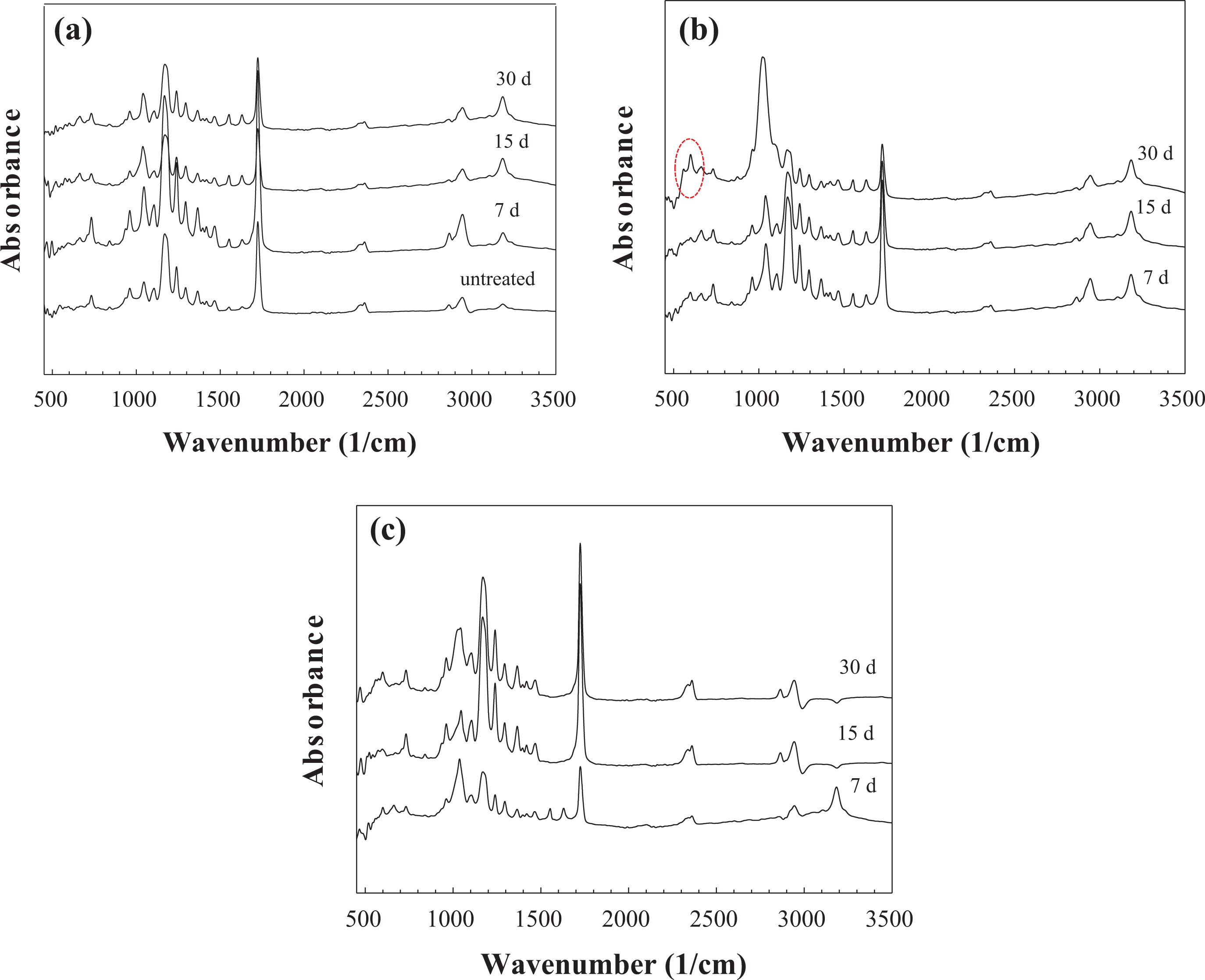
FTIR spectra of the PCL-bioactive glass composite fibers treated in SBF for different time intervals: (a) 1% BGP-PCL, (b) 5% BGP-PCL, and (c) 10% BGP-PCL. FTIR: Fourier-transform infrared; PCL: poly-ε-caprolactone; SBF: simulated body fluid; BGP: bioactive glass particle.
Atomic force microscopy (AFM) images of the bare and BG-containing PCL fibers treated in SBF for 30 days are shown in Figure 11. AFM images were obtained in scanning mode. Sharp silicon probes were used to collect the images. The brightness of features in captured topographic images increases as a function of height of the samples. The average roughness of SBF-treated bare PCL samples was measured to be 0.54 µm. On the other hand, the average roughness of 10% BGF-PCL and 10% BGP-PCL scaffolds was 0.57 µm and 0.64 µm, respectively. Higher roughness of the 10% BGP-PCL sample may be due to the higher bioactive response (HA layer formation) in SBF compared to other samples.
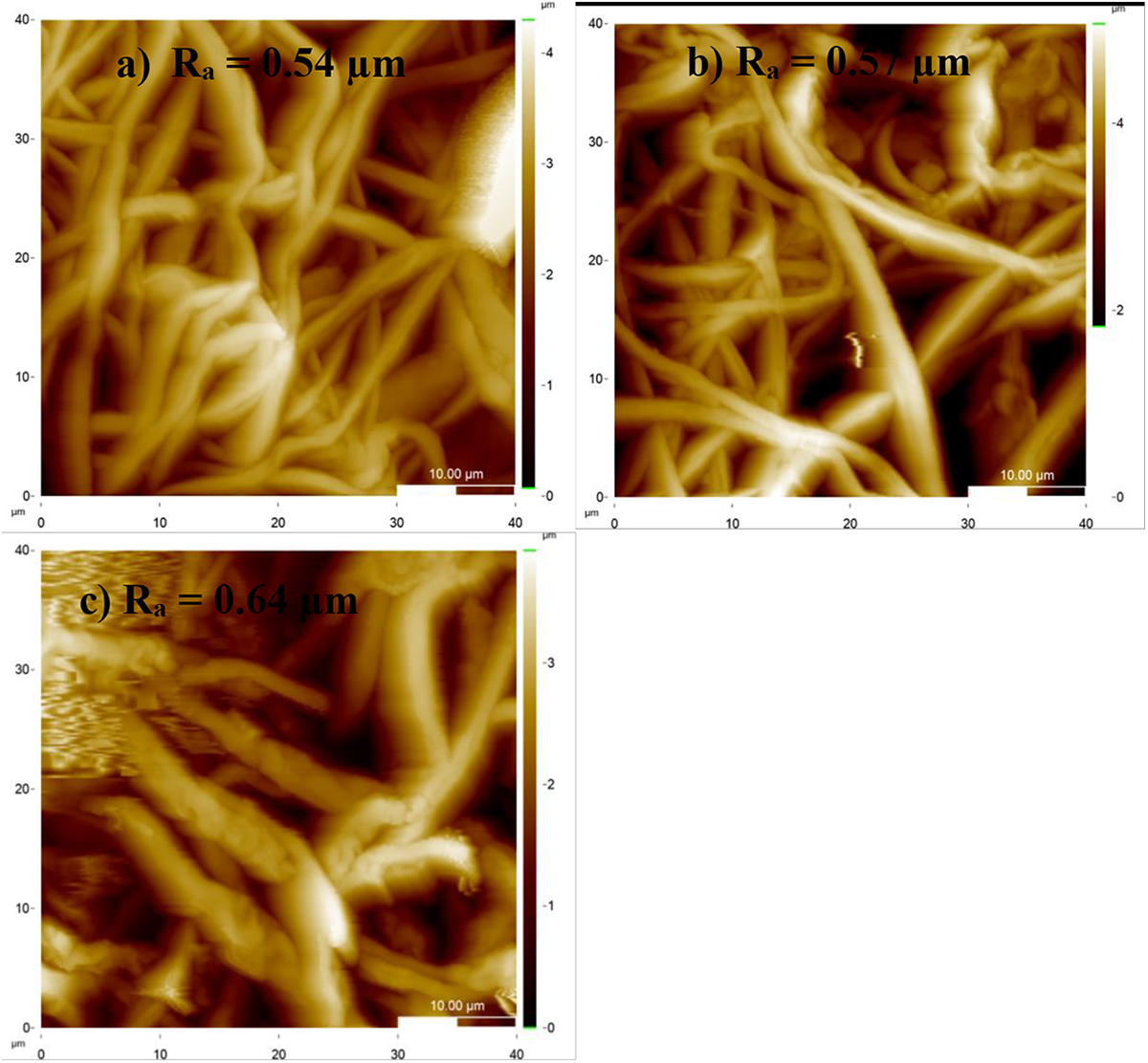
AFM images of the fibrous PCL-bioactive glass composite scaffolds treated in SBF for 30 days: (a) bare PCL, (b) 10% BGF-PCL, and (c) 10% BGP-PCL. PCL: poly-ε-caprolactone; SBF: simulated body fluid; BGF: bioactive glass fiber; BGP: bioactive glass particle; AFM: atomic force microscopy.
Degradation behavior and Si release
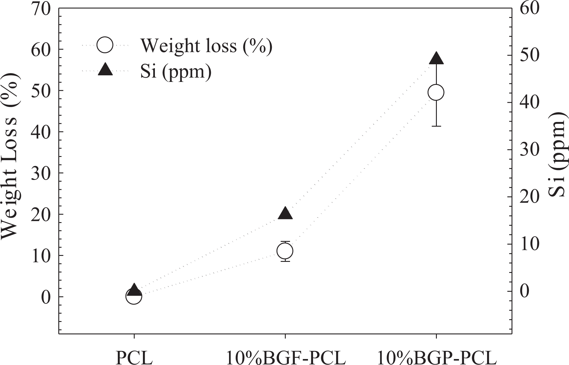
The experimental results for weight loss of the fibrous scaffolds are presented in Figure 12 for the pure PCL, 10% BGP-PCL, and 10% BGF-PCL immersed in the phosphate buffer saline (PBS) for 30 days. The results revealed that although PCL has a very low degradation rate, the combination with BG in the form of particle or fiber resulted in a faster degradation compared to PCL alone. This behavior suggests that the 13-93 BG acts as an accelerator for the degradation of PCL fibers in PBS presumably due to high surface reactivity in water. On the other hand, PCL is hydrophobic and has a highly crystalline structure that does not allow fast water penetration into the PCL bulk. Though the mechanism of PCL degradation is known as random hydrolytic chain scission of the ester linkage, the degradation kinetics was relatively slower than other degradable polyesters. 30 Based on Figure 12, the degradation percentage of 10% BGP-PCL fibers (49.43% ± 8.1) was higher compared to 10% BGF-PCL fibers (10.98% ± 2.4) under the same conditions. The lower degradation rate of BGF-containing PCL scaffolds may be attributed to the lower reactivity of these samples compared to BG-containing PCL scaffolds. The results are also consistent with the experimental findings obtained for the bioactivity of the composite PCL scaffolds.
Graph showing the weight loss and the silicium release behavior of the PCL-based fibrous scaffolds prepared in the study. PCL: poly-ε-caprolactone.
Previously, Díaz et al. 31 studied the degradation behavior and mechanical properties of PCL/nano-HA composite scaffolds in PBS at 37°C, over 16 weeks. The addition of nano-HA particles to the scaffolds accelerated the weight loss of the composites and increased their capacity to absorb water during the initial degradation process. 31 Similarly, Santocildes-Romero et al. 24 investigated the preparation of electrospun PCL composite membranes containing strontium-substituted BGPs. They reported accelerated polymer degradation due to interactions between both components. In the current study, accelerated degradation of PCL fibers in the presence of glass particles or glass fibers may be due to the rapid alkalinization of the medium, resulting in the release of acidic degradation products.
In the study, the amount of silicium ions being released into SBF was investigated under static conditions. The silicium concentration in SBF after immersion of the composite PCL fibrous scaffolds for 30 days was measured using ICP-OES (Perkin-Elmer, USA). The results showed that the glass particles and glass fibers were able to dissolve from the PCL composite fibers after immersion in SBF and releasing their dissolution products into the local environment. Si ions released from the 10% BGP-PCL sample were higher than the 10% BGF-PCL sample under the same conditions (Figure 12). Higher release rate was attributed to the higher degradation behavior of 10% BGP-PCL scaffolds.
Discussion
It is known that filler size may affect the strength, bioactivity, and cell proliferation of tissue engineering composite constructs. 32 In the study of Jo et al., 33 PCL/BG (60% SiO2, 36% CaO, and 4% P2O5 in mol%) nanocomposites fabricated using BGFs and compared with an established composite fabricated using microscale BG particles. The results showed that the PCL/BGF composite has greater biocompatibility and mechanical stability when compared with PCL/BG particle composites. However, in that study, PCL-BG composite films were prepared by solvent evaporation method and HA forming ability of the composites was not tested. Misra et al. 34 compared the influence of micro (5 μm) and nano (29 nm) -sized bioactive glass particles when mixed into a P(3HB) polymer matrix. They observed that the addition of nano-size bioactive glass has a greater impact on the mechanical and structural properties of composite films than micro-size fillers. The increase in degradation and swelling was more obvious for nanocomposites than microcomposites. 34
The BGFs used in the current study have sizes on the submicron scale, therefore their specific surface area is much larger than that of BGPs with micron scale. Because of their high surface area, BGFs can interact sufficiently with the organic matrix and react efficiently with the physiological environment such as SBF. However, it is important to note that synthesis methods for 13-93 fibers and particles used in the study were different and this may affect the final acellular bioactivity of these glasses. In the study of Deliormanlı, 21 it was reported that a crystalline Ca-P layer, formed only after 7 days for the electrospun 13-93 fibers immersed in SBF at 0.5 mg ml−1 fiber/SBF ratio. On the other hand, a different study 35 on the in vitro mineralization of PCL (20 wt%) coated 13-93 glass scaffolds (produced by melt-cast glass particles) proved the HA formation just after 3 days of immersion in SBF. Similarly, Fu et al. reported the formation of HA phase by thin-film XRD analysis on the surface of the sintered 13-93 glass scaffolds immersed in a SBF for 7 days. 36 Therefore, slight differences may be found on the in vitro mineralization ability of the glass fibers and the particles utilized in the study.
In addition, the results of the current study showed that BGPs can be distributed evenly in the PCL matrix because of their unimodal size distribution. However, BGFs have to be chopped into short fibers prior to use and particle size analysis showed that they have some agglomerates in the short fiber form with a high aspect ratio and this may affect their distribution inside the PCL matrix.
Conclusions
PCL fibrous scaffolds incorporated with 13-93 BGPs or BGFs were successfully fabricated by electrospinning. The effect of BG morphology on the in vitro bioactivity of composite scaffolds was investigated. An increase was observed in PCL fiber diameter by the addition of the BG phase to the system both in the form of particle and fiber. However, fiber diameter was higher in the glass particle–containing system compared to the glass fiber–containing composite system. Based on the results of morphological and structural analyses, BGP-PCL scaffolds demonstrated higher reactivity and higher conversion rate to HA in SBF compared to BGF-PCL scaffolds. Additionally, silicium ion release and degradation rate of BGP-PCL scaffolds in phosphate buffer were higher compared to BGF-PCL samples. These differences presumably caused by the dimensional and morphological characteristics of BG fillers as well as their surface reactivity. The difference was also attributed to better dispersion of glass particles inside the PCL matrix compared to glass fibers. PCL-based fibrous composite scaffolds prepared in this study can find applications for bone tissue engineering applications.
Footnotes
Declaration of Conflicting Interests
The author(s) declared no potential conflicts of interest with respect to the research, authorship, and/or publication of this article.
Funding
The author(s) received no financial support for the research, authorship, and/or publication of this article.