
Abstract
This study proposes a novel tab for the tensile testing of unidirectional (UD) carbon fiber-reinforced thermoplastic polyamide 6 (CF/PA6) to reduce stress concentration at the tab end. The length of the new tab is identical to that of the UD CF/PA6 specimen to avoid a sudden change in geometry that is typically observed in a conventional tab end. Additionally, three types of UD CF/PA6 laminates from different manufacturers are used to fabricate tensile specimens. Specimens with a new tab and a conventional nontapered tab are tested under quasi-static tension. Finite element simulations of tensile testing are also performed for specimens with two types of tabs. The experimental and simulation results demonstrate that the newly designed tab reduces the stress concentration at the tab end by approximately 10% and improves the estimates of tensile strength for the UD thermoplastic composite laminates.
Introduction
The ultimate tensile strength of unidirectional (UD) composite materials in the fiber direction is one of the most basic mechanical properties of continuous fiber-reinforced composite materials. Therefore, an accurate measurement of the tensile strength of UD composite materials in the fiber direction is important for the design and application of composite materials. In the cases of conventional homogeneous and isotropic materials, such as various metals and plastics, specimens for tensile testing are easily machined into dog bone or hourglass geometries and are expected to fail in the waist section of the specimen. However, in the cases of continuous fiber-reinforced composite materials, machining a UD specimen into a dog bone or hourglass shape causes discontinuity in the specimen fibers from the wide clamp region to the waist region. Additionally, machining composite materials easily induces various damages near the machined surface, and this may reduce the tensile strength of the specimen. The high cost of machining a shaped specimen of composite materials is also a disadvantage. Therefore, various national and international standards 1 –5 recommend the use of flat and straight-side specimen geometries with end tabs to prevent clamp failure. However, in tabbed specimens, there are high stress concentrations near the tab end due to the sudden changes in terms of geometry, material and the transfer of stress from the shear stress between tab and specimen to the tensile stress in the specimen. A high stress concentration near the tab end causes specimen failure at a stress significantly lower than real strength and this leads to an underestimation of tensile strength in the UD composite specimen.
A few efforts focused on investigating the effects of tab shape and tab material on the tensile testing of UD composite laminates over the past decades. 6–12 Numerical results of stress distribution, as reported by Cunningham et al. 6 and Lévesque et al., 7 indicate that stress concentration at the root of the nontapered tab significantly exceeds the one at tapered tab. Conversely, Hojo et al. 8 experimentally investigated the effects of a nontapered tab and a 10° tapered tab on the tensile strength of UD carbon fiber-reinforced (thermosetting) plastics (CFRP). Their experimental results revealed a small difference (3–4%) in the tensile strength in the fiber direction of tabbed specimens of two types. Most specimens failed near the tab end and inside the tab. Furthermore, 60–85% specimens with the tapered tab broke inside the tab within the region between the tapered and nontapered parts, while 20–55% specimens with nontapered tab broke slightly inside the tab. High shear stress and low shear strength in the tapered region between the tapered tab and the specimen easily produce debonding between the tapered part of the tab and the specimen. Debonding significantly deletes the effect of the tapered part on the reduction of stress concentration at the tab end. Lavoie et al. 9 also indicated that it is difficult to measure the real strength of UD laminates in the fiber direction through the tensile testing of UD specimens. Two multidirectional layups of [90/0/90]s and [90/±45/0]s were recommended to measure the tensile strength of UD laminate indirectly. Maheri 10 and Wisnom et al. 11 developed a specimen with a waist region with respect to the thickness using a ply dropoff layup technique. An improvement of 9.4–13.7% in the tensile strength was reported by Lavoie et al. 9 when compared to those of a flat specimen with respect to the thickness. However, the fabrication of this kind of specimen is not cost-effective. Baere et al. 12 numerically and experimentally investigated the effects of tab shape and tab layup on the tensile strength of [(0, 90)]4s carbon fiber-reinforced poly phenylene sulfide (PPS) numerically and experimentally. Here, PPS is a type of thermoplastic resin and (0, 90) represents a layer of fabric of a 5-harness satin weave. Their numerical results indicated that tapered tab results in a lower stress concentration at the tab end as opposed to the nontapered tab. However, the chemical inertness of the PPS results in a poor bond between tab and specimen, and thus, the authors proposed the use of a nontapered tab for carbon fiber-reinforced thermoplastic (CFRTP). The result indicated that it is more difficult to expect the effect of tapered tab on the reduction in the stress concentration at the tab end of CFRTP specimens, due to the poor bond between the tab and specimen, when compared to those of thermosetting resin-based composite specimens. Therefore, further study is necessary to reduce the stress concentration at the tab end of CFRTP specimens.
The present study proposes a novel tab for the tensile testing of UD carbon fiber-reinforced thermoplastic polyamide 6 (CF/PA6) to reduce stress concentration at the tab end. The new tab is fabricated from aluminum and it has the same length as the UD CF/PA6 specimen to avoid the sudden change in geometry as observed in the conventional tab end. Furthermore, three types of UD CF/PA6 laminates fabricated by different manufacturers are used to fabricate tensile specimens. Specimens with new tab and conventional nontapered tab are tested under quasi-static tension. Numerical simulations are also performed for specimens with two types of tabs. The cost-effectiveness of the new tab design is examined based on numerical and experimental results.
Experimental
Materials and specimens
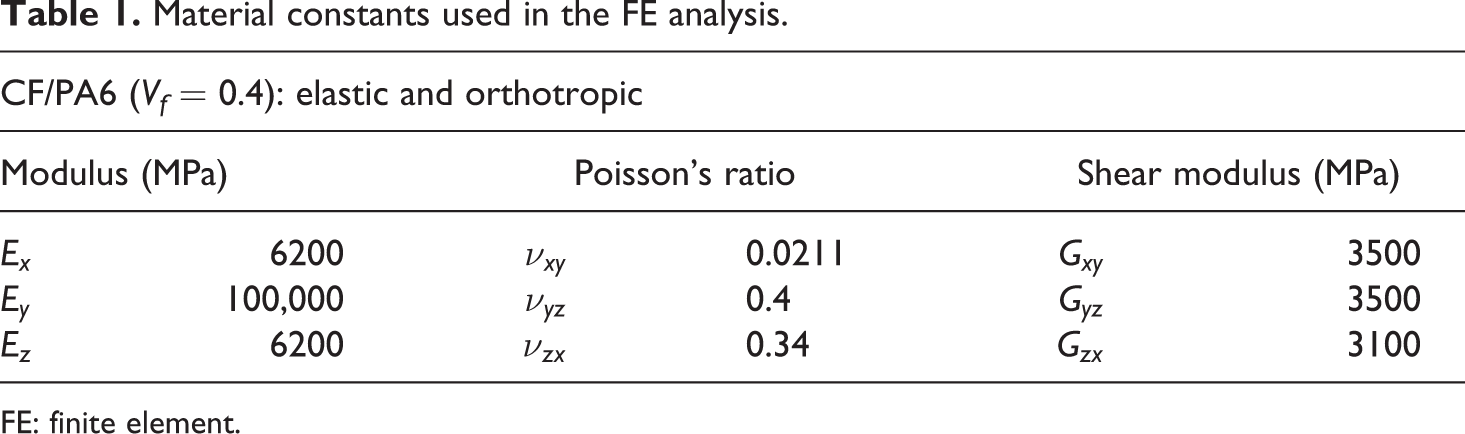
In this study, three different types of UD CF/PA6 laminates fabricated by three different manufacturers of CF/PA6 tapes are used to investigate the validity of newly designed tab for the tensile testing of UD CF/PA6. The first laminate AFPT CF/PA6 UD laminate[0°]8 is made from Celstran® CFR-TP PA6 tape and fabricated by AFPT GmBH (Germany) using laser assisted thermoplastic fiber placement technology. The nominal thickness of Advanced Fibre Placement Technology (AFTP) laminate is 1.2 mm. The process temperature is 250°C, tape speed is 9 mm/min, cooling temperature is 100°C, and consolidated pressure is 0.2 MPa. The second laminate Maruhachi CF/PA6 UD laminate [0°]8 is made from Maruhachi CF/PA6 8exe®-U prepreg with spread carbon fiber tow and fabricated by Maruhachi Corporation (Japan) using hot pressing technology. The nominal thickness of Maruhachi laminate is 1.4 mm. The process temperature is 235°C and the consolidation pressure is 3 MPa. The third laminate TenCate CF/PA6 laminate [0°]8 is made from TenCate Cetex®-TC910 CF/PA6 tape and fabricated by Maruhachi Corporation (Japan) using hot pressing technology. The nominal thickness of TenCate laminate is 1.2 mm. The process conditions are as same as those used in the fabrication of Maruhachi laminate. An aluminum alloy 2024-T3 plate with 1 mm thickness is used to make the tab since the aluminum alloy plate can be easily machined into any shape and and corresponds to a low-cost material when compared to fiber-reinforced plastics.
Specimens of 20 × 250 × thickness (mm3) are cut from the CF/PA6 UD laminates using a water cooled diamond cutter and designed following the national standards of ASTM D 3039/D 3039M and JIS K7073 with a gauge length of 150 mm. The specimen is 5 mm wider than the recommended specimen width with respect to the standards because the new tab has a long central slot of 6 mm wide for bonding a strain gauge on the specimen. Dimensions of tabbed specimens with two types of tabs are shown in Figures 1 and 2. The conventional nontapered tab as shown in Figure 1 is a rectangular tab of 20 × 50 × 1 mm3. The new tab depicted in Figure 2 has the same length as the CF/PA6 specimen to reduce the stress concentration caused by the sudden change in the geometry of the conventional tab end. A long slot is made at the central area of the tab to measure the tensile strain at the center of CF/PA6 specimen. Tabs are bonded to the two surfaces of specimens using 2-ethyl cyanoacrylate adhesive CC-33A (Kyowa Electronic Instruments Co., Ltd., Japan). The bonding length between specimen surface and the tab is 50 mm at both ends of the specimen. Additionally, a thin Kapton film is inserted at the gauge length between CF/PA6 specimen and the new tab to prevent the adhesive from adhering throughout the gauge length. Typical tabbed specimens are shown in Figure 3. A strain gauge is bonded to the central surface of each tabbed CF/PA6 specimen to measure the tensile strain of the specimen. In the case of specimen with the new tab, an additional strain gauge is bonded to the central surface of aluminum tab to measure the tensile strain of the aluminum tab. According to the limitation of composite laminates, each type of tabbed specimens are fabricated using three specimens from AFPT and Maruhachi laminates and six specimens from TenCate laminates.
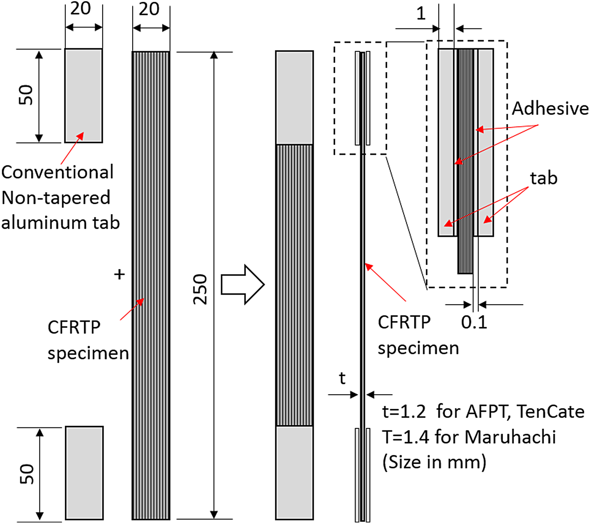
Dimensions of a specimen with the conventional nontapered aluminum tab.
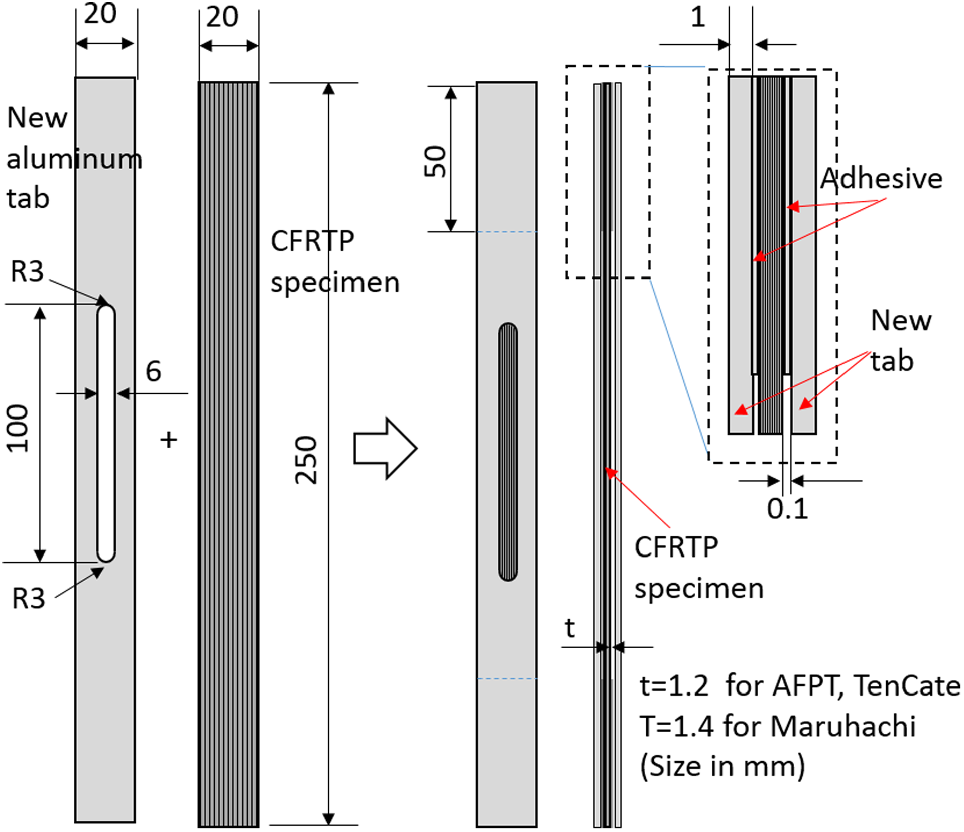
Dimensions of a specimen with the newly designed aluminum tab.
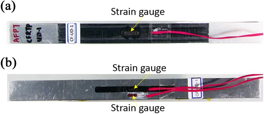
Images of typical tabbed specimens with different tabs: (a) specimen with the conventional nontapered tab and (b) specimen with the new tab.
Tensile testing
Tensile tests of tabbed specimens are performed using MTS 810 servo-hydraulic material testing system (MTS system corporation) at a constant crosshead speed of 1 mm/min. The testing machine is operated using a personal computer and a TestStar digital controller system (MTS system corporation). All tests are conducted under ambient conditions. Each specimen is clamped using hydraulic wedge grips. Based on the ASTM D 3039/D 3039M and JIS K7073 standards, the clamping length is approximately 50 mm and clamping pressure is set at 10 MPa to avoid slipping. Tensile load and tensile strain that occur in the specimen are recorded. Furthermore, three specimens of the aluminum alloy plate used to make tabs are also tested under tension to measure the elastoplastic stress–strain curve of the material. The specimen of the aluminum alloy plate is 250 mm in length, 25 mm in width, and 1 mm in thickness. The tensile tests of aluminum specimens are conducted using the same material testing system and crosshead speed as aforementioned for the tensile tests of CF/PA6 specimens.
Tensile stress at the center of CF/PA6 specimen with conventional tab is calculated as follows

where F denotes the tensile load applied on the specimen and A CFRTP denotes the cross-section area at the center of the CF/PA6 specimen. In the case of specimen with new tab, the tensile stress at the center of CF/PA6 specimen is calculated as follows

where F denotes the tensile load applied on the specimen including aluminum tab, A Al denotes the total cross-section area of aluminum tab at the center, and σAl denotes the stress that occurs in the central parts of aluminum tab and is calculated based on the measured strain in the central part of tab and the stress–strain curve obtained from the tensile test of aluminum plate. The tensile strength of the specimen is defined by the tensile stress at the maximum tensile load. The tensile modulus of the specimen is calculated from the chord modulus of its stress–strain curve as between 0.1% and 0.4% strain levels, 8 since the tensile modulus of the carbon fiber increases with an increase in the applied tensile strain due to the reorientation of graphite crystal in the fiber. 13 –15 The fiber volume fraction for the CF/PA6 laminate of each kind is evaluated based on the measured tensile modulus and the mixture law.
Finite element simulation of tensile testing
In addition to experimental efforts, finite element (FE) simulations of UD CF/PA6 specimens with different tabs under tensile and clamping loads are also conducted to investigate the differences in the stress concentration at the tab end or clamping end for two types of tabbed specimens. Geometries and boundary conditions of two analysis models for the specimens with the conventional tab and new tab are described in Figures 4 and 5, respectively.—Two FE models are three-dimensional.
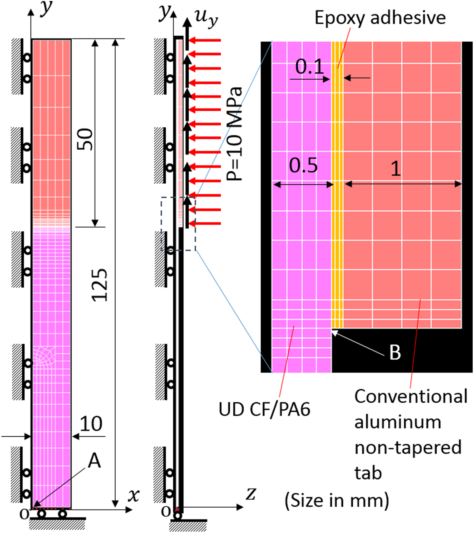
Analysis model for a specimen with the conventional tab.
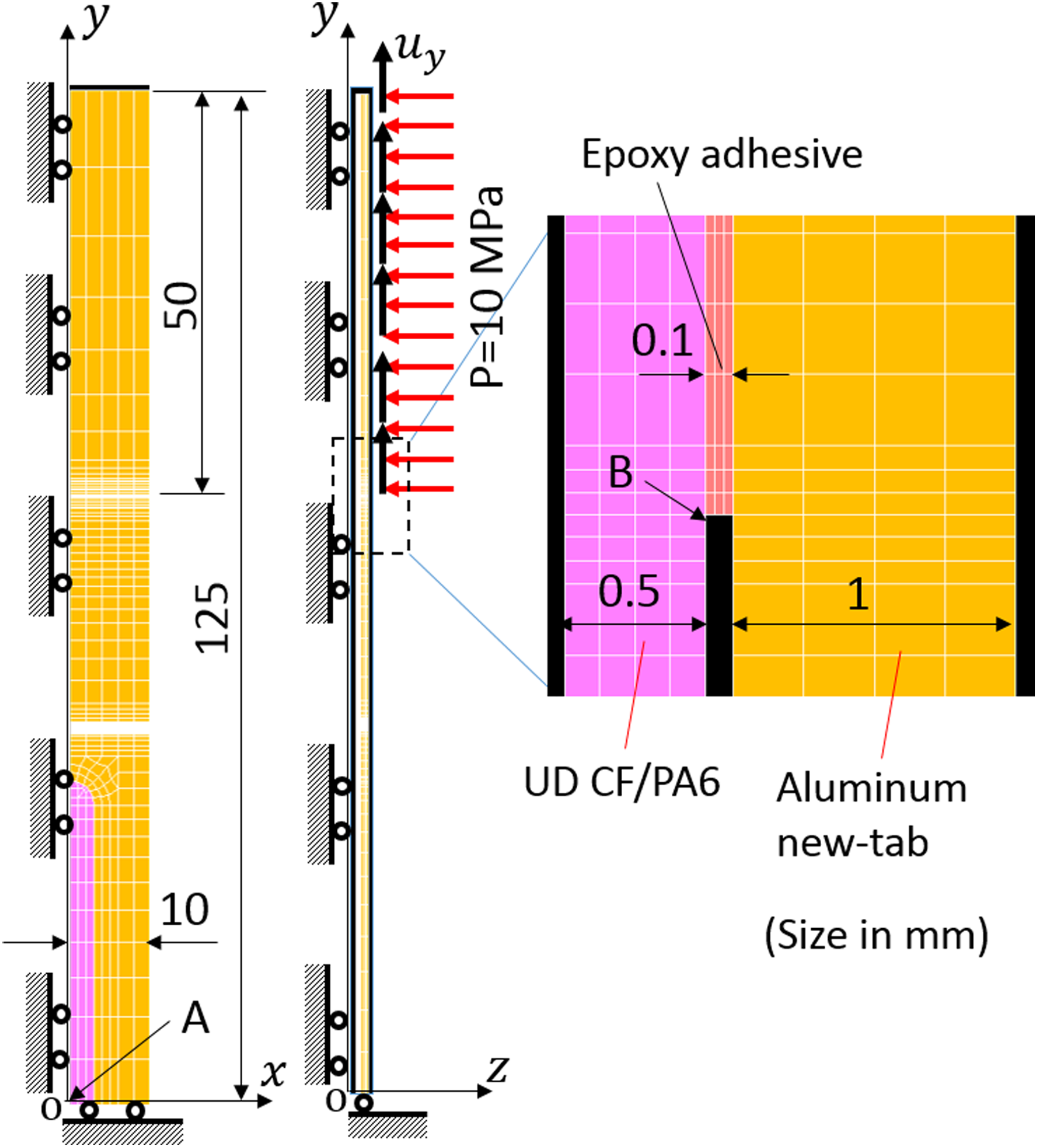
Analysis model for a specimen with the new tab.
Based on the symmetry of the tabbed specimens, only one-eighth of the specimens were modeled for the two types of tabbed specimens. The adhesive layer between the tab and the specimen was modeled using a thin resin layer of 0.1 mm thickness. Description of the coordinate axes of the models is as follows: the origin is located at the center of the UD CF/PA6 region; x–y plane is in the mid-plane (z = 0) of the model; x-axis is in the width direction of the specimen; y-axis is in the longitudinal direction of the specimen and this also corresponds to the tensile load direction; and z-axis is in the thickness direction of the specimen. The loading conditions applied on the tab surface are designated by the horizontal and vertical arrows. The horizontal arrows represent the uniform clamping pressure of 10 MPa and the vertical arrows indicate the applied uniform tensile displacement of 1.25 mm. It is to be noted that the reason of using the displacement of 1.25 mm is because it causes an average tensile strain of 1.67%, which is close to the maximum failure strain obtained from the aforementioned tensile tests of UD CF/PA6 laminates. The UD CF/PA6 laminate is considered as linear elastic and orthotropic, and the material constants used in the present simulation are listed in Table 1. The aluminum tab is considered as isotropic and elastoplastic with Young’s modulus of 70GPa, Poisson’s ratio of 0.3, and a yield stress of 360 MPa. The elastoplastic stress–strain curve, which is measured by the tensile testing of aluminum specimens, is used to simulate the elastoplastic deformation of the aluminum tab. The adhesive layer is considered as isotropic and linearly elastic with Young’s modulus of 3GPa and Poisson’s ratio of 0.42. The hexahedral element of 8 nodes is used in the two simulation models. The mesh is refined around the tab end and the clamping end. The stress ratio between stresses at points A and B is used to evaluate the stress concentration at the tab end or the clamping end. Point A denotes the central point (x = 0, y = 0, z = 0.5) of the UD CF/PA6 specimen surface and point B denotes the adhesive end point (x = 0, y = 75, z = 0.5) that coincides with the tab end for specimens with the conventional nontapered tab or the clamping end for specimens with the new tab. Thus, the adhesive end, tab end and clamping end indicate the same location at the CF/PA6 specimen surface. Nonlinear analysis of two models are performed using the nonlinear structural analysis software MSC Marc 2011.
Material constants used in the FE analysis.
FE: finite element.
Results and discussions
Experimental results
Micrographs of three UD CF/PA6 laminates are shown in Figure 6(a) to (c) for AFPT, TenCate, and Maruhachi laminates, respectively. In Figure 6 (a) to (c), the two images at the upper left and lower left depict the polished surfaces that are normal and parallel to the fibers, respectively, whereas the right image shows the enlarged image of a typical region that is normal to the fibers. A layer-like fiber distribution in the AFPT laminate, a bundle-like fiber distribution in the TenCate laminate, and a spread bundle-like fiber distribution in the Maruhachi laminate are observed. Evidently, the present UD CF/PA6 laminates exhibit a nonuniform fiber distribution, which is significantly different from the nearly uniform fiber distribution in conventional aircraft-grade UD CFRP laminates.
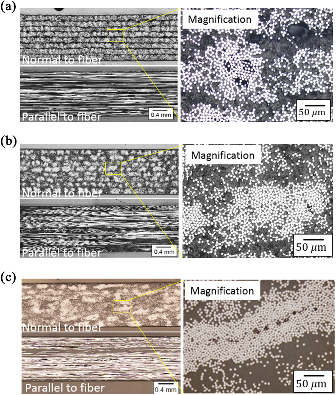
Micrographs of the three UD CF/PA6 laminates: (a) AFPT UD laminate; (b) TenCate UD laminate; (c) Maruhachi UD laminate. UD: unidirectional; CF/PA6: carbon fiber-reinforced thermoplastic polyamide-6.
Stress–strain curves of the three aluminum alloy specimens are described in Figure 7, and extremely good reproducibility is observed. For simplicity in the calculation of the stress that occurs in the aluminum tab, the stress–strain curve of aluminum alloy is approximately described by a bilinear curve expressed by the following equations


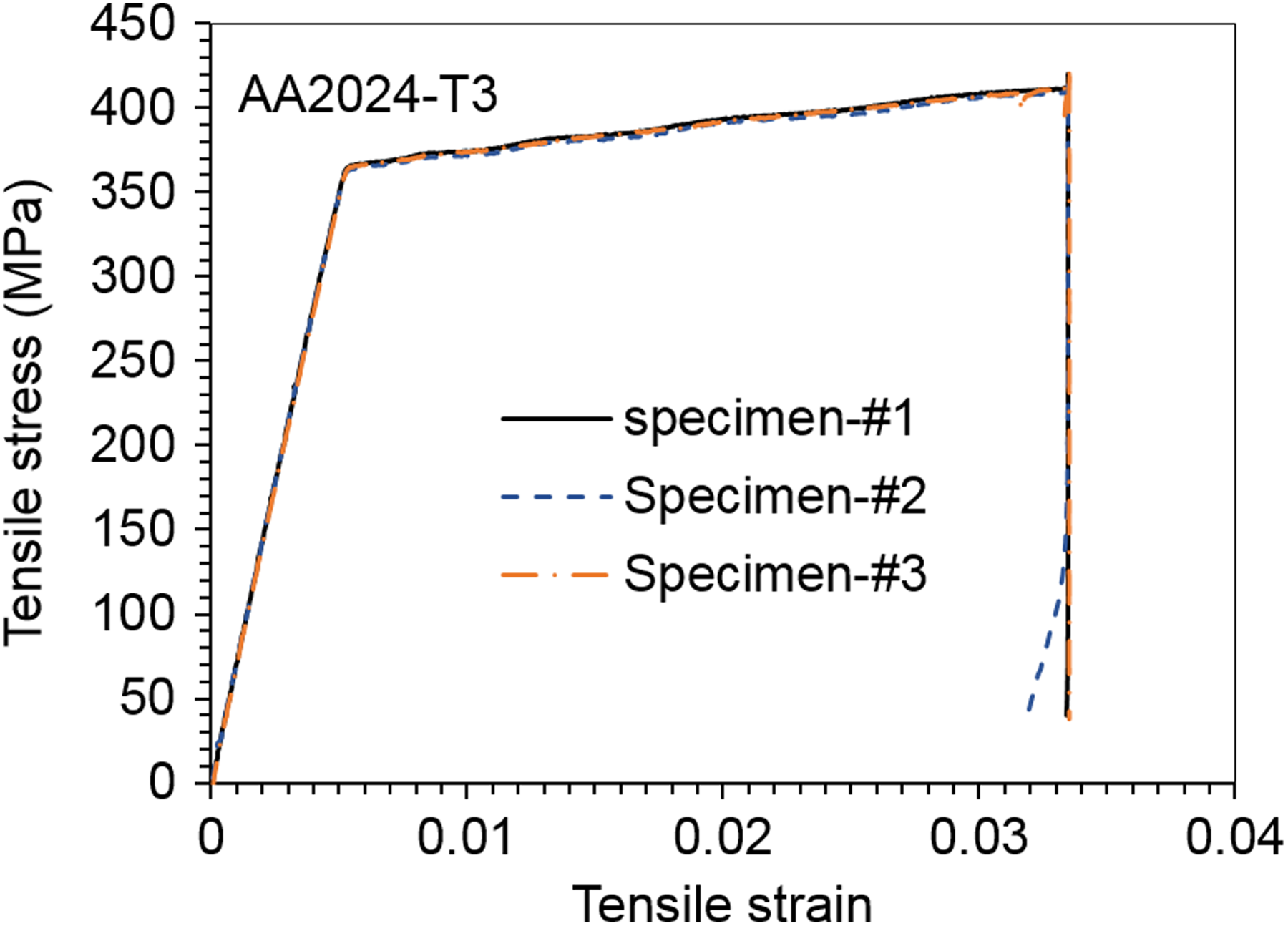
Stress–strain curves of the three aluminum alloy specimens.
where, the unit of stress is MPa. Subsequently, the stress that occurs at the center of the new tab is easily calculated using measured strain εAl and the equations specified above. The typical stress–strain curves obtained from tensile testing of various specimens are described in Figure 8(a) to (c) for the three UD CF/PA6 laminates, respectively. Stresses are calculated based on tensile load using equation (1) for the specimens with the conventional tab, and equations (2) to (4) for the specimens with the new tab. Higher tensile strength values and higher failure strains are evidently measured in the specimens with the new tab when compared to those with the conventional tab. The details of the results of tensile tests for all specimens are listed in Table 2. The AFPT specimens with the new tab exhibit an increase of approximately 9.5%, the Maruhachi specimens with the new tab exhibit an increase of approximately 10.7%, and the TenCate specimens with the new tab exhibit an increase of approximately 10% in tensile strength, when compared to the related specimens with the conventional tab. The improvement of approximately 10% in the tensile strength is close to the previous experimental results 9 that were obtained from the tensile tests of specimens with a thickness waist region. The results demonstrate that the new tab is a cost-effective method to obtain higher tensile strength by reducing the stress concentration at the tab end. Conversely, specimens of different types of laminates yield different values of the coefficient of variation (CV) of the tensile strength. Specimens of TenCate laminate exhibit relatively large CV values, and it is considered that this is caused by the relatively significant nonuniform fiber distribution in the TenCate laminate. Typical failure images of various specimens are shown in Figure 9. Failure of specimens starts near the tab end for specimens with the conventional tab and starts near the clamping end for specimens with the new tab. These aforementioned facts indicate the additional efforts are needed to further reduce the stress concentration at the clamping end of the new tabbed specimen.
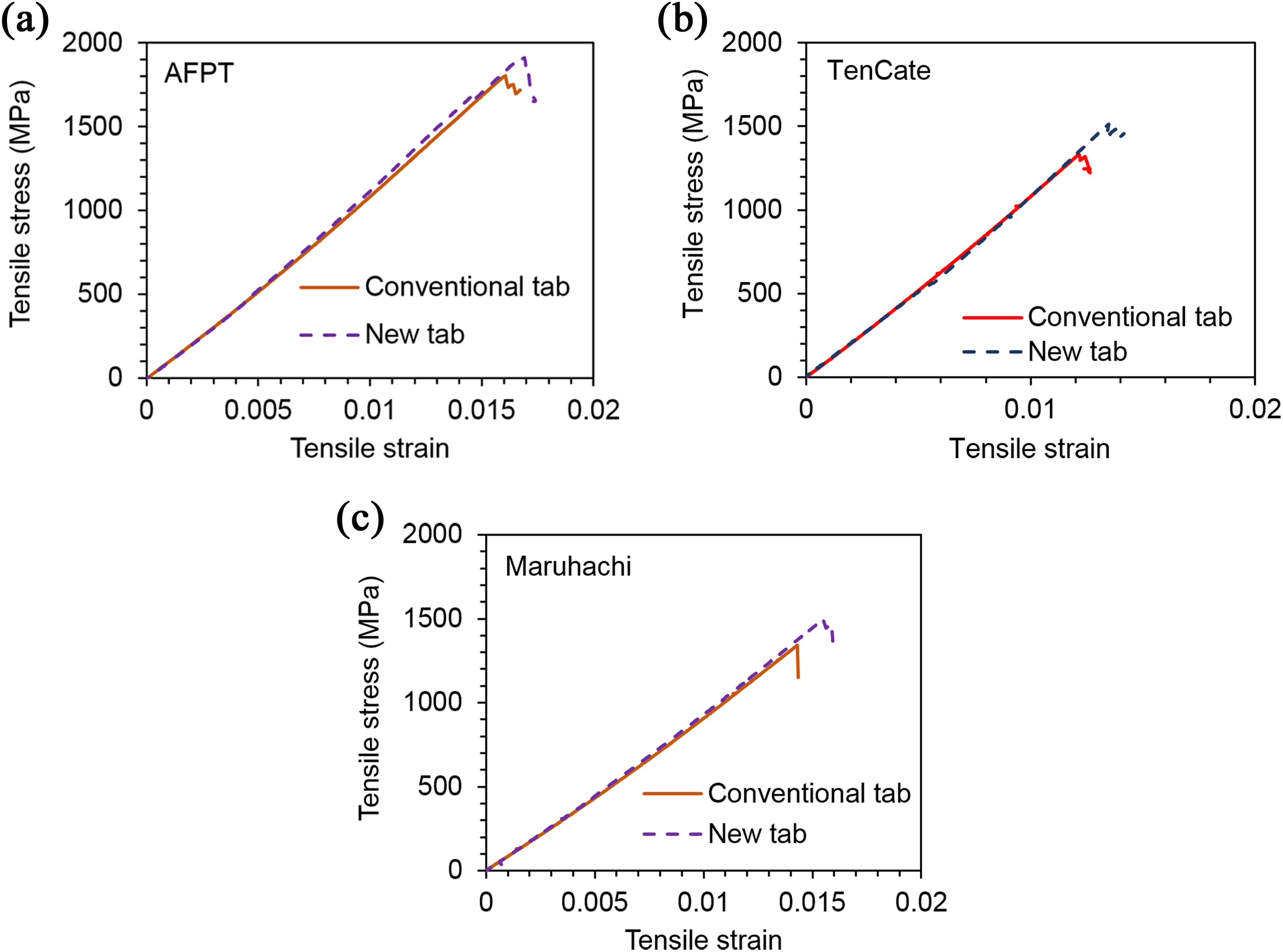
Typical stress–strain curves of various UD CF/PA6 specimens under tension: (a) AFPT specimens, (b) TenCate specimens, and (c) Maruhachi specimens. UD: unidirectional; CF/PA6: carbon fiber-reinforced thermoplastic polyamide-6.
Results of tensile tests of various UD CF/PA6 specimens.
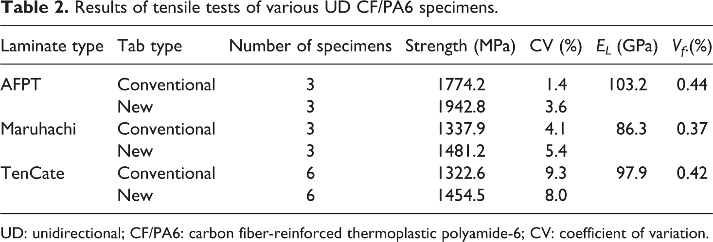
UD: unidirectional; CF/PA6: carbon fiber-reinforced thermoplastic polyamide-6; CV: coefficient of variation.
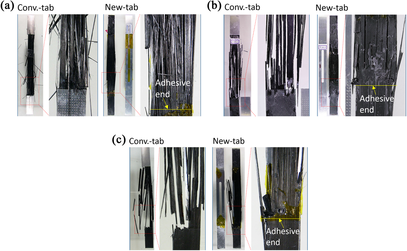
Typical failure images of various UD CF/PA6 specimens: (a) AFPT UD laminate, (b) TenCate UD laminate, and (c) Maruhachi UD laminate. UD: unidirectional; CF/PA6: carbon fiber-reinforced thermoplastic polyamide-6.
Results of the FE analysis
Numerical results obtained from FE analysis are illustrated in Figures 10 and 11. Tensile stress distributions on the top surface and side edge of specimens are shown in Figure 10(a) for the specimen with the new tab and Figure 10(b) for the specimen with the conventional tab. High stress concentration near the adhesive end is observed at the specimen surface. Tensile stress distributions that are normalized by the tensile stress at point A along the longitudinal direction of the specimens are depicted in Figure 11. It is observed that the normalized tensile stresses in both models with the new tab and the conventional tab are almost constant from y = 0 to approximately y = 70 mm, after which they rapidly increase and reach their peaks near the adhesive end. The specimens with the conventional tab exhibit a peak value of approximately 11% higher than that of the specimen with the new tab. The analysis results are consistent with the tensile testing results. Hence, it is preferable to use a new tab for the reduction in the stress concentration at the adhesive end. Normalized peeling stress σz and shear stress σyz between the tab and the specimen are shown in Figure 12. Both models show similar stress distributions and the difference in their peak values is low. It is noted that the stress values are obtained from the averaged values at the nodes on the model surface. Thus, these are not exactly the values of stresses on the surface, and a few values of stresses below the surface are used in calculating averaged values at the nodes. Thus, these values do not correspond to zero prior to 75 mm. Despite this approximation, significantly high peeling stress and shear stress are observed near the adhesive end. These stresses easily cause debonding between the tab and the specimen if the clamping end does not cover the adhesive end because the adhesive strength between the tab and the CFRTP specimen is very low when compared with the tensile strength of the specimen.
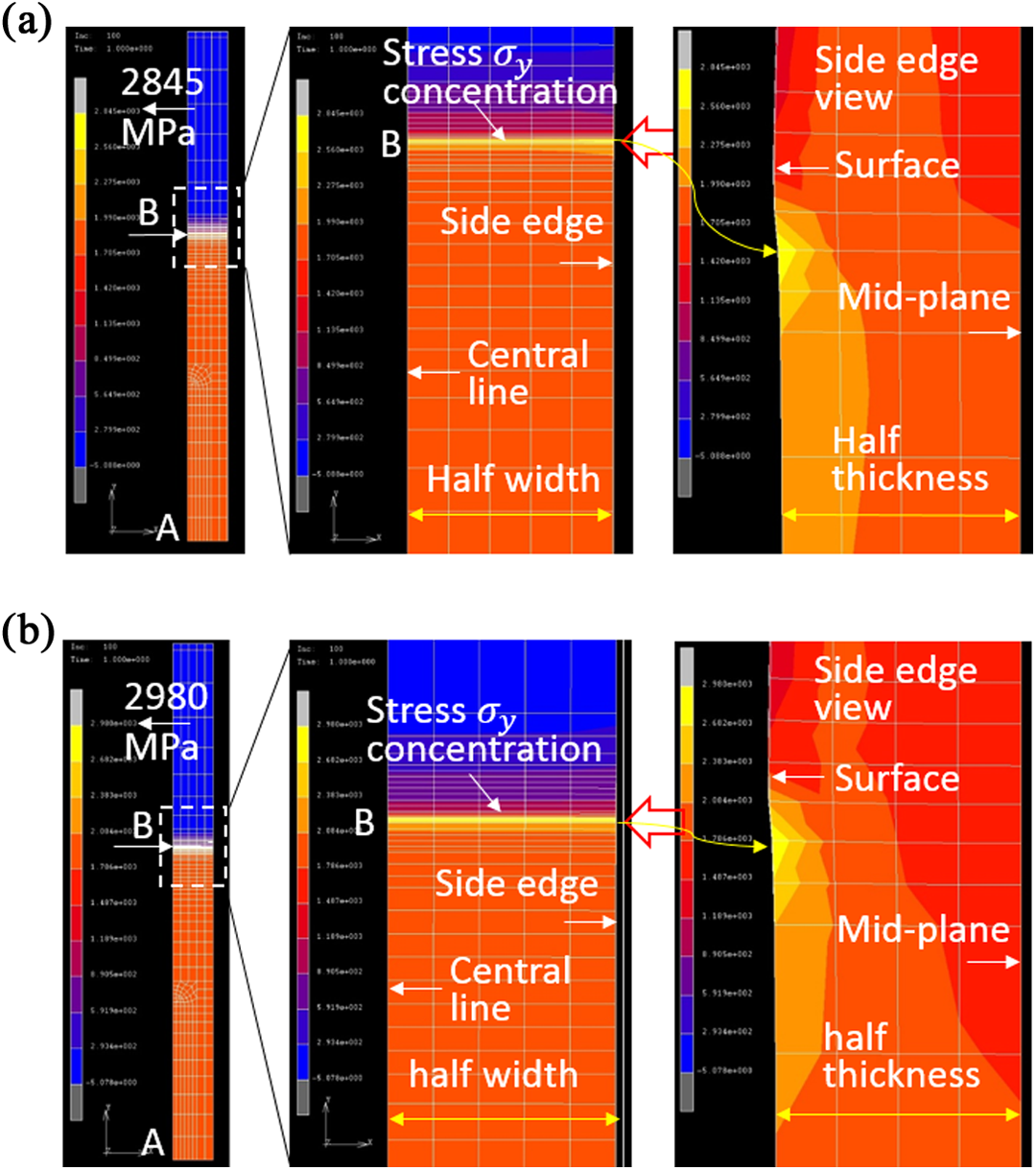
Tensile stress distributions on the top surface and side edge surface of the CF/PA6 region of specimens: (a) specimen with the new tab and (b) specimen with the conventional tab. CF/PA6: carbon fiber-reinforced thermoplastic polyamide-6.
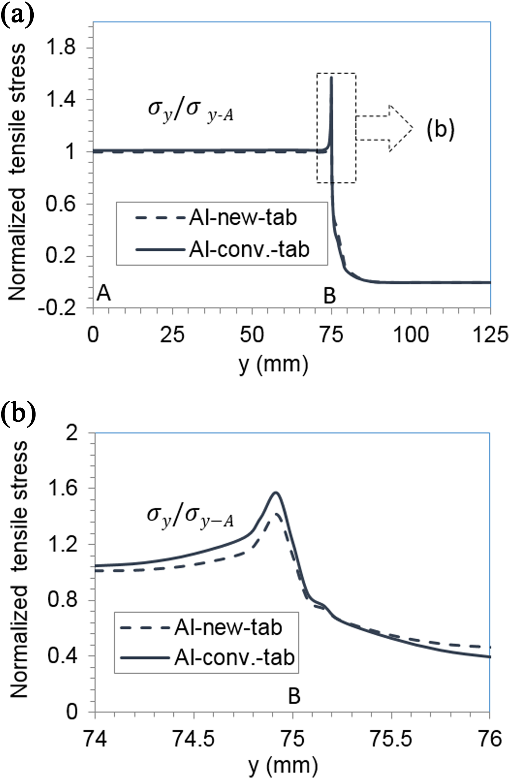
Normalized tensile stress distributions along the longitudinal direction of the specimens. (a) Along the whole length and (b) near the tab end or the adhesive end.
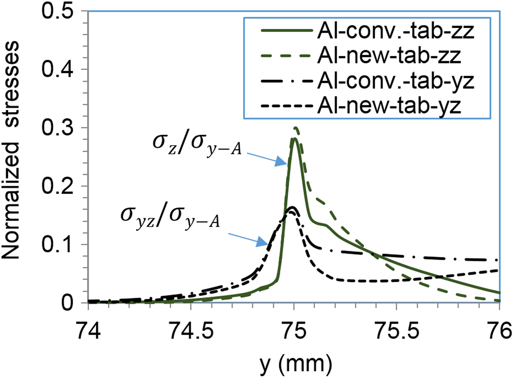
Normalized peeling stress and shear stress distributions along the longitudinal direction of the specimens.
Conclusions
In this study, a novel tab for the tensile tests of UD CFRTP composites is proposed to reduce the stress concentration at the tab end. Tensile testing and FE simulations are conducted for CFRTP specimens with a conventional tab and new tab. Based on the present experimental and numerical analysis results, it is concluded that the new tab reduces the stress concentration by approximately 10% near the tab end. Thus, the new tab provides a cost-effective method to improve the estimation of tensile strength during the tensile testing of UD CFRTP laminates. However, a stress concentration still exists near the adhesive and clamping end, and thus more efforts are needed to further improve the estimation of tensile strength of UD CFRTP laminates.
Footnotes
Acknowledgements
The first author thanks Ministry of Higher Education Malaysia (MOHE) for the PhD scholarship. The authors thank Mr Kenzou Yasuda and Mr Hiroshi Kushiku from NHK Spring Co., Ltd for providing the thermoplastic composite laminates.
Declaration of Conflicting Interests
The author(s) declared no potential conflicts of interest with respect to the research, authorship, and/or publication of this article.
Funding
The author(s) received no financial support for the research, authorship, and/or publication of this article.