
Abstract
In this article, the high-performance polymer composites were prepared based on the morphology designing method. To begin with, the beta transcrystalline morphology in the interfacial region of isotactic polypropylene (iPP) composites supported by single carbon fiber was formed by the induction of beta nucleating agent (NA) and verified using the polarized light microscopy. Then, to further explore the application of the beta transcrystalline morphology, the way of induction by supported NA was introduced into the iPP injection-molded samples. The result showed that a certain number of interfacial beta transcrystallinity was formed in the adjacent region of carbon nanotubes–modified iPP injection-molded samples. Herein, the mechanical properties are closely related to the interfacial beta transcrystalline morphology, the convective evidence was the improvement of the sample’s impact strength by seven times. Therefore, this work gives a new perspective for the preparation of high-performance composites materials via morphology designing.
Keywords
Introduction
The transcrystallinity is a kind of commonly existing crystalline morphology in material research, especially in the polymer composites. 1 There is still a question of whether interfacial crystallization can ultimately bring effective interfacial enhancement or not, which has been argued for a long time. 2 However, considering the strong interface as well as the high modulus and strength of the transcrystallinity layer, a better reinforcing effect can be expected, so many researchers agree with the improvement in mechanical properties of polymer composites in the presence of transcrystallinity at the micrometer or nanometer scale. 3,4 Beta transcrystallinity is a kind of transcrystallinity which attracts more attentions in polymer science because of its contribution on high impact resistance of polymer matrix. To explore the formation of beta transcrystallinity, Varga first investigated the different crystal growth process in isotactic polypropylene (iPP) composites sandwich thin film, and found the heterogeneous nucleation mechanism for transcrystallinity. 5 Due to the heterogeneous nucleation of transcrystalline morphology, the formation of beta transcrystallinity in iPP matrix is difficult under normal conditions. The beta transcrystallinity of PP has been found to be formed by shearing the sandwich film such as single CF-reinforced iPP composites. 6 Although shearing the sandwich film is a direct-viewing way to investigate the formation of iPP beta transcrystallinity, the utilization of this method is limited in the sandwich films and hard to extend to other engineering application, such as injection molding. In order to meet the requirements of large-scale application, it is eager to promote the formation of beta transcrystalline morphology in the polymer matrix. It is reported that the enhanced nucleation density contributes to the formation of transcrystalline morphology in the interfacial region of injection-molded polymer composites. 7,8 Nucleating agent (NA) can greatly increase the nucleation density, as shown in many reports. 9 It is reported that the beta transcrystallinity can be formed at the surface of fiber if appropriate beta NAs (BNAs) were used to coat the fiber. 10 While, if the combination of BNA and fiber is only via weak van der Waals force, BNA will flake off easily during the following molding processes, such as extrusion or injection molding. Chemical modification of fiber surface has been utilized to improve fiber/matrix adhesion. 11 The impact resistance of the matrix can be improved by the increase in the interaction between filler and matrix. 12 Herein, by chemically supporting the BNA onto the surface of CF or carbon nanotubes (CNTs), the transcrystalline morphology will be induced in CF/PP or CNTs/PP composites and thus the mechanical properties of the composites were increased. In this work, the method of chemical modification will be used in CF/PP and CNTs/PP composites, the morphology was affirmed by polarized light microscopy (PLM) and scanning electron microscopy in the BNA-supported single carbon fiber (CF)–filled iPP sandwich films and the BNA-supported CNTs-modified iPP injection samples, respectively. Also, the relationship between the morphology structure and the mechanical properties of BNA-supported CNTs-modified iPP injection-molded samples will be explored.
Experimental
Material and sample preparation
The commercial grade iPP, T30 S, with a melt flow rate of 2.3 g/10 min (ASTM D1238, 230°C, and 2.16 kg load) from LanZhou petroleum Chemical Co., Ltd (PR China) was used in this study. A shortcut ribbon-like polyacrylonitrile-based CF, T300, purchased from NanTong SuTong Carbon Fiber Corporation (PR China), was used in the preparation of sandwich film. The multi-wall CNT (MWCNT) with a diameter of about 8 nm and the length of about 10–30 µm, synthesized from methane by a catalytically chemical vapor deposition, was supplied by Chengdu Institute of Organic Chemistry, Chinese Academy of Science, China. The received MWCNTs were chemically treated and 5.58 wt% of hydroxyl groups were attached to the tube wall.
The iPP/single fiber thin films were prepared as follows. First, the single CF was supported by BNA according to our previous work. 6 Then, a single BNA-supported CF was placed between two pieces of iPP sheets on a glass slide. Then, the glass slide was fixed on the hot stage and covered by another glass slide which prevents adhering of molten iPP to the upper plate of the hot stage. Using the heat controller, the temperature was first raised up to 200°C over a period of 3 min to erase the previous thermal history of the sample. When the iPP melted, it surrounded the whole portion of the fiber located under the upper slide. After that, it was cooled to room temperature, and then the microcomposites were successfully prepared.
The BNA-supported MWCNT-modified iPP samples were prepared according to a two-step process. Namely, master batches were first prepared through melt compounding of BNA, MWCNT, and MWCNT-supported BNA with iPP resin in an internal mixer at a barrel temperature of 200°C and an apparent shear rate of 30 r min−1 for 5 min. Secondly, all the master batches were melt compounded with iPP resins in an SHJ-20 corotating twin screw extruder (Nanjing Shengchi Co., Ltd., China) with a screw diameter of 25 mm, a length/diameter ratio of 23, and a temperature profile of 190°C, 210°C, 230°C, and 225°C from the feeding zone to the die. The extrudates were then pelletized. The pellets were dried and injection-molded into dumb-bell tensile samples and impact samples on a PS40E5ASE precise injection-molding machine, with a temperature profile of 190°C, 210°C, 230°C, and 225°C from the feeding zone to the nozzle. Both the injection pressure and the holding pressure were 37.4 MPa.
Characterization
The morphology of the BNA chemically supported single CF-filled iPP sandwich film was investigated by a Leica DMIP Polarized Light Microscopy (PLM) (Leica Co., Ltd., UK) equipped with a Linkam THMS 600 hot stage (Linkam Co., Ltd., UK). The microcomposite was heated to 200°C over a period of 5 min to erase the previous thermal history, followed by a rapid cooling (10°C min−1) to 125°C, then isothermally crystallized for 30 min at 125°C.
The melting behavior test was performed on a Q20 (TA Instrument Co., Ltd., USA) differential scanning calorimeter (DSC) under nitrogen atmosphere. The calibration of the temperature and heat flow scales at the same heating rate was performed with indium. The sample was quickly heated up to 200°C and held at 200°C for 5 min prior to crystallization to erase the effect of the thermal–mechanical history. Then, the sample was cooled from 200°C to 100°C at a rate of 10°C min−1. After that, the sample was heated up to 200°C from 100°C at a rate of 10°C min−1 to obtain the melting behavior. Wide-angle X-ray diffraction (WAXD) measurement was carried out on a D/max-rA X-Ray Diffract meter (Rigaku Co., Ltd., Japan) at room temperature. The copper K α (wave length = 1.542 nm) irradiation source was operated at 40 kV and 100 mA. Diffraction patterns were recorded by monitoring diffractions from 3° to 50°, and the scanning speed was 3°C min−1. The samples for DSC and WAXD tests were cut from the interphase region of the microcomposites near the BNA chemically supported CF.
A Hitachi S3400+EDX SEM instrument (Hitachi Co., Ltd., Japan) was used to observe the morphologies of BNA-supported MWCNT-modified iPP injection samples. The injection-molded samples were fractured in liquid nitrogen after 0.5 h immersion. The fracture surfaces etched by a mixed acid solution were coated with gold and observed at an accelerating voltage of 10 kV.
Atomic force microscopy (Keysight 7500 AFM, Agilent Technologies, USA) was used for recording the surface phase morphology of the samples. The probes were used in piezoelectric ceramics with tapping mode. The normal spring constant of the e cantilever was 48 N m−1 and the force between tip and sample was 2.89 V.
Results and discussion
Crystalline morphology development of iPP composites
Figure 1 shows the crystalline morphology of iPP sandwich thin film in the presence of the BNA chemically supported single CF (a, b, c, and d) and virgin CF without BNA supported (e, f, g, and h). For each sample, four photographs were taken from 10–360 s during the isothermal crystallization process at 125°C. At the beginning, after 10 s isothermal crystallization, hardly no heterogeneous nucleation occurs on the CF surface as shown in Figure 1(a). The situation improved after isothermal crystallization for 120 s, as shown in Figure 1(b), and a few nucleating points appear on the surface of the CF and it started to grow around the CF surface. While after 240 s as given in Figure 1(c), the fiber surface was covered by the crystals growing from the heterogeneous nucleation with high nucleation density. At the interphase region of the sandwich thin film, the growth of lamellae was restricted in the lateral directions by neighboring entities, and then the growth direction of such surface-nucleated crystals was normal to the surface. In this way, a beta transcrystalline morphology finally formed in the sandwich thin film as shown in Figure 1(d). To further assign the crystal type and comparison, Figure 1(e) to (h) shows a typical alpha transcrystallinity in iPP/single CF microcomposites obtained at the same condition as shown in Figure 1(a) to (d). Compared with Figure 1(e) to (h), the growth of crystals on the single CF surface, as shown in Figure 1(a) to (d), reflects a beta transcrystallinity, which has a negative radial texture compared with the alpha one. A number of studies have shown that the beta transcrystallinity of iPP can be formed under a certain temperature region of 130°C or certain condition such as melt shearing. 1,2 In this work, the beta transcrystalline morphology formed easily at 125°C. The special interfacial morphology was attributed to crystalline structure transition induced by the BNA-supported single CF.
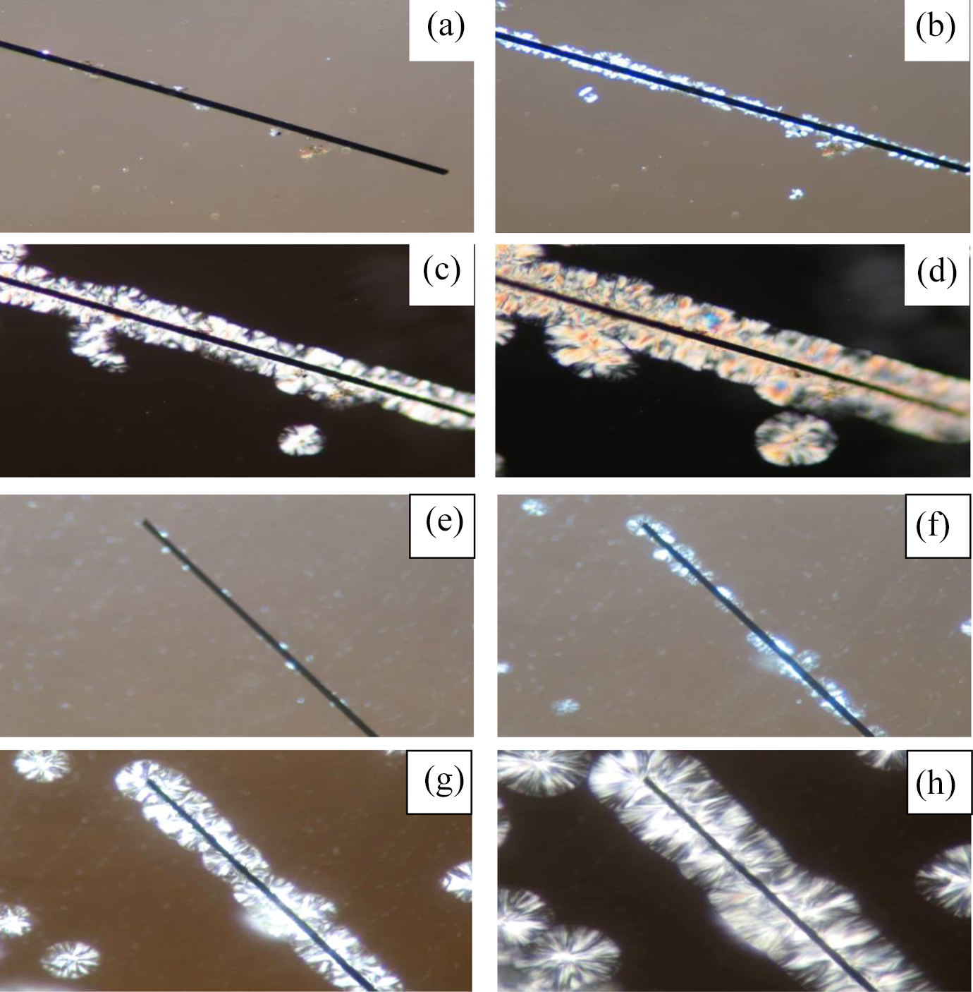
The morphology of beta (a, b, c, and d) and alpha (e, f, g, and h) transcrystallinity formed during crystallization of BNA-supported single CF-filled iPP microcomposite at 125°C: (a and e) isothermal crystallizing for 10 s; (b and f) isothermal crystallizing for 120 s; (c and g) isothermal crystallizing for 240 s; (d and h) isothermal crystallizing for 360 s. CF: carbon fiber; iPP: isotactic polypropylene; BNA: beta nucleating agent.
To validate the crystalline morphology in the microcomposites, DSC and WAXD tests were performed on the interphase region of chemically supported CF in the sandwich film with BNA. The results are shown in Figure 2. As shown in Figure 2(a), in the melting curve of the microcomposite, a significant endothermic peak appears at 148°C, which was assigned to the melting point of beta crystals of iPP. Figure 2(b) shows that a diffraction peak appears at the 2θ angle of 16.3°, which was assigned to the (300) diffraction of beta crystals of iPP. Both the results further proved that the transcrystalline morphology induced by the BNA chemically supported CF was beta transcrystallinity of iPP.
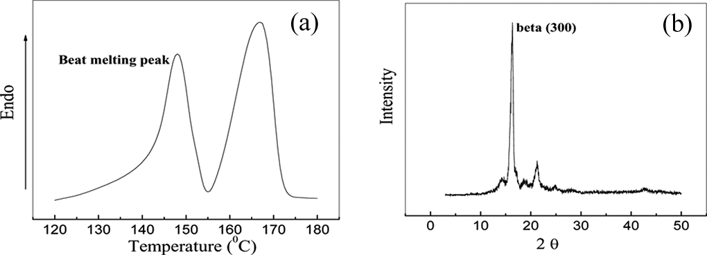
BNA-supported single CF-filled iPP microcomposite: (a) melting behavior and (b) WAXD curve. CF: carbon fiber; iPP: isotactic polypropylene; BNA: beta nucleating agent; WAXD: wide-angle X-ray diffraction.
Figure 3 shows the crystalline morphology of BNA and supported BNA-modified iPP injection-molding samples at 125°C for 30 s. Different layers of the CNT-supported BNA-modified iPP injection samples were explored. It can be seen that without supported CNT, the morphology of iPP beta crystal shows irregular rules. While in the BNA-supported CNTs sample, the orientated morphology of iPP beta crystal appears at 100 µm away from skin and the most obvious in the 400 µm away from skin. This trend has been less obvious at 800 µm away from skin as it was closer to the core layer, which is related to the disorder degree of the polymer chain motion at the core layer.
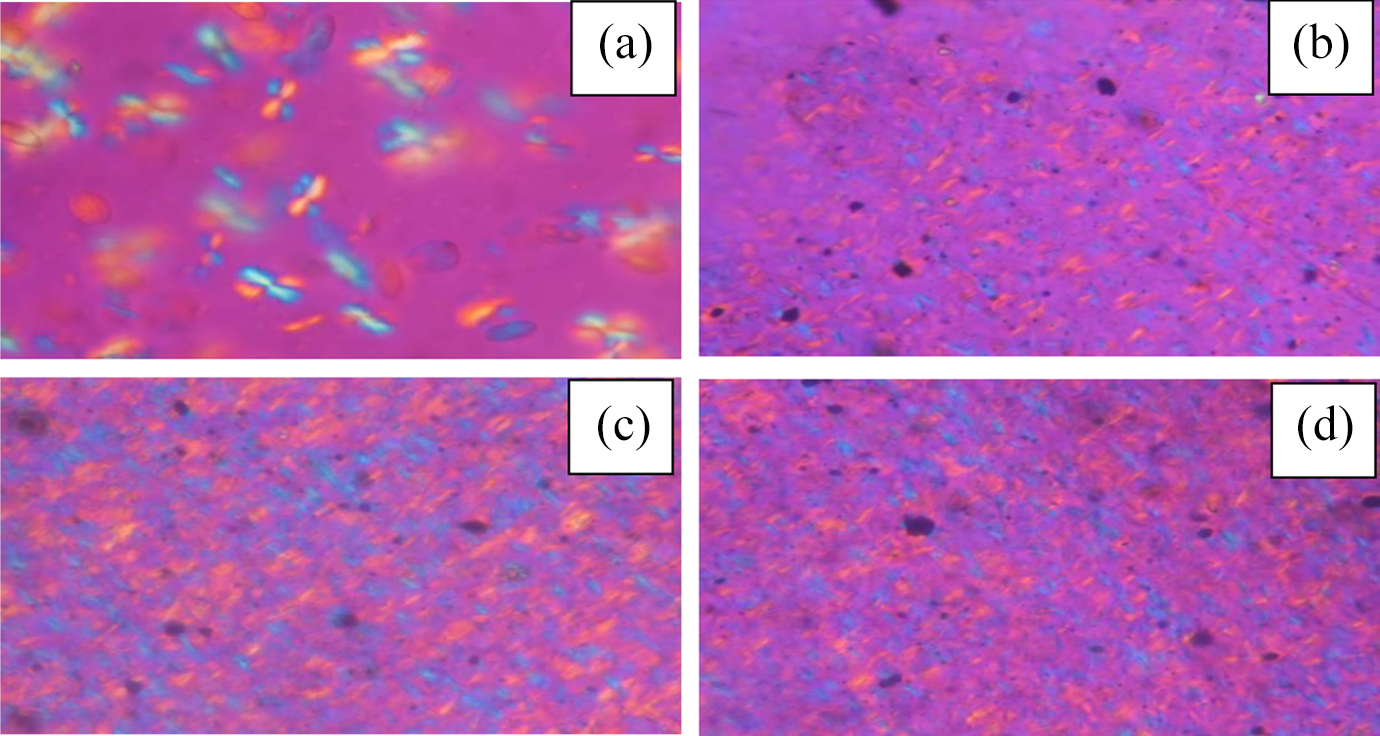
Crystalline morphology of modified iPP injection-molding samples at 125°C for 30 s: (a) iPP filled with BNA 400 µm away from the skin; (b) iPP filled with BNA-supported CNTs 100 µm away from the skin; (c) iPP filled with BNA-supported CNTs 400 µm away from the skin; and (d) iPP filled with BNA-supported CNTs 800 µm away from skin. iPP: isotactic polypropylene; BNA: beta nucleating agent; CNT: carbon nanotube.
Relationship between crystalline morphology and mechanical properties
It has been reviewed that the nanometer scale may not always be able to significantly influence the performance of the final products. Figure 4 shows the comparison of impact property of BNA-supported MWCNTs-modified iPP and virgin iPP samples. It was visible that the impact strength of supported system was largely increased compared with that of pure iPP and BNA-modified iPP samples. This result has been attributed to the enhanced nucleating ability of BNA-supported CNTs. 6 Now, it will be further conformed that the enhanced nucleating ability is attributed to the formation of beta transcrystalline morphology in the interphase region of BNA-supported MWCNTs-modified iPP injection-molded samples. The transcrystallinity can greatly improve the impact resistance of modified iPP samples, which was in accordance with the previous work.
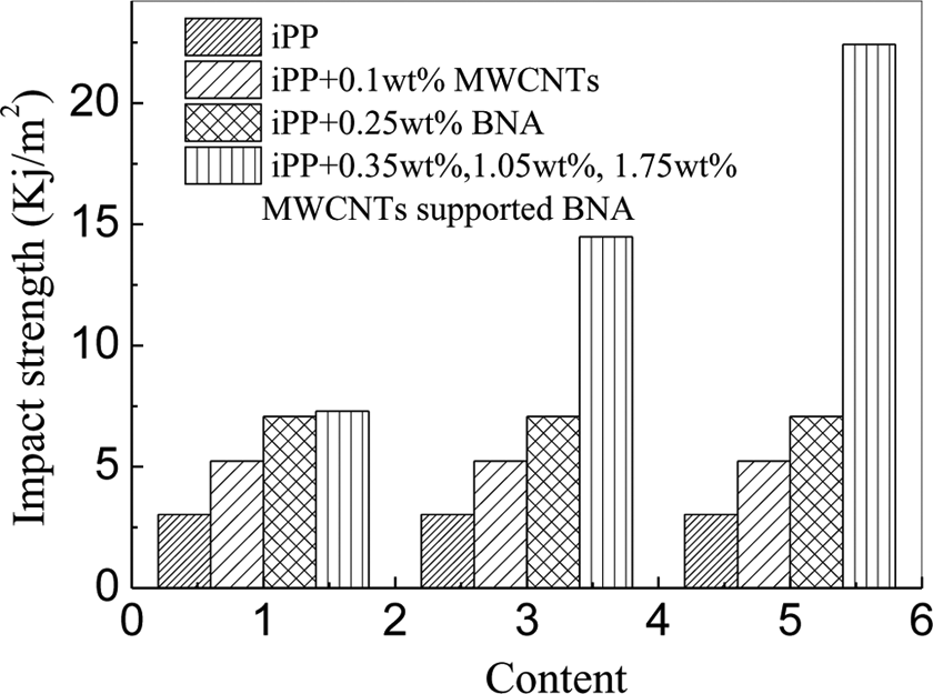
Impact strength of iPP and modified iPP injection-molded samples. iPP: isotactic polypropylene.
Structure validation
Figure 5(a) to (d) shows the etched fracture surface of BNA chemically supported MWCNTs-modified iPP injection samples. The typical sector texture in Figure 5(a) to (d) indicates that the BNA chemically supported MWCNTs successfully induced beta crystals in the matrix. It should be pointed out that, as shown in Figure 5(a) to (d), CNT was across the sector texture and the crystal growth direction was perpendicular to the nanotube surface, especially at the near-core layer of the samples shown in Figure 5(d). Due to the morphology and growth mechanism of the crystals, it is reasonable to illustrate that the beta transcrystallinity had formed in the interphase region of modified iPP injection-molded samples. The parallel caves in the Figure 5(a) assumed to be the BNA-supported MCNTs, which have induced the beta transcrystallinity. As the length of the MWCNTs has a wide distribution, short MWCNTs prefer to appear in the skin layer during the injection-molding process. For comparison, the etched surface of virgin without BNA-supported MWCNTs-modified iPP injection samples was shown in Figure 5(e) to (h). Although the sector texture can also be, as shown in Figure 5(e), a result of the existing BNA, the MWCNTs in the iPP matrix showed a random distribution. No sector texture was found near the caves of the skin layer as shown in Figure 5(e), as well as no nanotube transfixed the crystals as shown in Figure 5(f) and (g). Furthermore, in the near core layer as shown in Figure 5(h), the nanotube even shows a bended morphology which indicated that the nanotube seems expelled by the near crystals instead of transfixing it. So no beta transcrystalline morphology was formed in the MWCNTs without chemically supported BNA-modified iPP injection-molded samples.
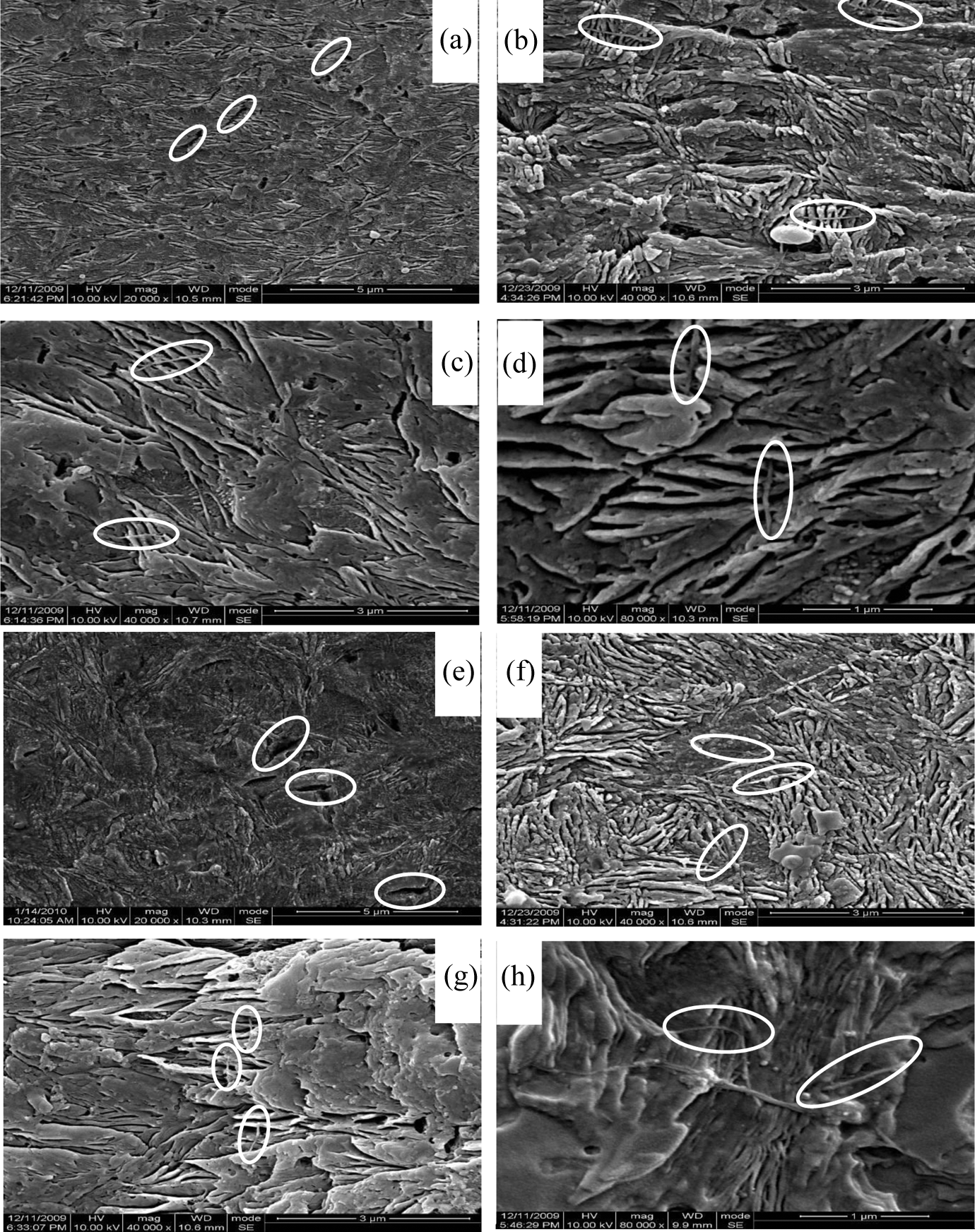
SEM images of BNA chemically supported (a, b, c, and d) and unsupported (e, f, g, and h) MWCNTs-modified iPP composites. The samples were perpendicular to the flow direction. (a and e) 0 µm, (b and f) 200 µm; (c and g) 800 µm; and (d and h) 2000 µm from the skin to core layer of the injection-molded samples. iPP: isotactic polypropylene; BNA: beta nucleating agent; MWCNT: multi-wall carbon nanotube; SEM: scanning electron microscope.
Figure 6 shows the AFM images of BNA chemically supported MWCNTs-modified iPP composites. As shown in the images, the CNT shows an orientated structure and it was surrounded by supported BNA-induced beta transcrystalline structure, which finally increased its diameter. This result also gives an evidence for the formation of beta transcrystalline in the modified iPP composites.
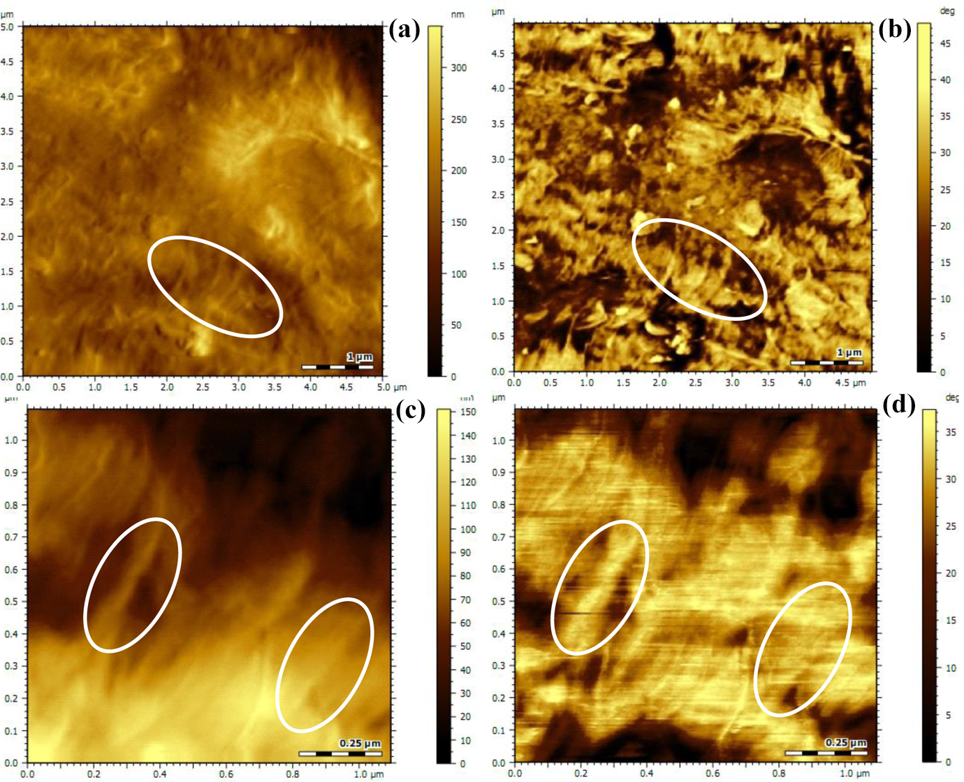
AFM images of BNA chemically supported MWCNTs-modified iPP composites: (a) morphology image 5 × 5 µm2; (b) phase images 5 × 5 µm2; (c) morphology image 1 × 1 µm2; and (d) phase images 1 × 1 µm2. iPP: isotactic polypropylene; AFM: atomic force microscope; BNA: beta nucleating agent; MWCNT: multi-wall carbon nanotube.
Conclusion
The beta transcrystalline morphology can be formed in both iPP/single fiber microcomposites and BNA-supported CNTs-modified iPP injection-molded samples. The improvement of impact resistance of BNA-supported CNTs-filled iPP injection-molded samples by seven times was attributed to the formed interfacial beta transcrystallinity.
Footnotes
Acknowledgement
The authors acknowledge the National Science Fund (no. 51603192 and no. 11372286), Basic and Advanced Technology Research Project of Henan Province (No.152300410033, No.162300410003), and Open Project of State Key Laboratory Cultivation Base for Nonmetal Composites and Functional Materials (no. 15zkfk06) for their financial support.
Declaration of Conflicting Interests
The author(s) declared no potential conflicts of interest with respect to the research, authorship, and/or publication of this article.
Funding
The author(s) disclosed receipt of the following financial support for the research, authorship, and/or publication of this article: This work was financial supported by the National Science Fund (no. 51603192 and no. 11372286), Basic and Advanced Technology Research Project of Henan Province (No.152300410033, No.162300410003), and Open Project of State Key Laboratory Cultivation Base for Nonmetal Composites and Functional Materials (no. 15zkfk06). This work was sponsored by the Scientific Research Foundation for the Returned Overseas Chinese Scholars, State Education Ministry.