
Abstract
In this study, a new type of carbon nanotube (CNT) and micro fiber (carbon or basalt)-reinforced polyamide 6 hybrid composites were prepared and investigated. Hybrid composites were produced by melt compounding, and specimens were injection molded. Thanks to the proper dispersion of CNT, a remarkable increment in tensile properties was exhibited. The scanning electron microscopy of the fracture surfaces of the tensile-tested materials revealed that during composite preparation the presence of the fibers in the melt facilitated a better dispersion of the CNT, which explains the enhancement in the tensile properties. The deformation components of the materials were also examined at different load levels. The presence of carbon nanotubes decreased residual deformation at every applied load level. Protruding fiber length investigation revealed that improved mechanical properties are not related to fiber-matrix adhesion but to the reinforcing and stress homogenization effect of nanotubes in the matrix.
Keywords
Introduction
The spread of polymer matrix composites in the industry is continuous owing to their excellent mechanical properties and relatively small density. Besides thermoset composites, this is also true for thermoplastic matrix ones. The injection molding of thermoplastic composites is a widely used technology in the electronic and automotive industry because these growing industries have high production demands. 1 The most commonly used reinforcing material is glass fiber, 1,2 although carbon fibers (CF) are also applied in large amounts due to their high strength and modulus. Together, polyamide 6 (PA 6) and CF can reach high strength and modulus. 3,4 Nevertheless, a market breakthrough has not come yet for CF, since its price is relatively high. Another competitor of glass fiber can be basalt fiber (BF), which has similar mechanical properties to glass fiber, but its thermal and chemical resistance is far better and its production is simpler as well, therefore it can become a real alternative to glass fiber in the field of composites in the future. 5,6
In the last few decades, different types of nanoparticles have been discovered. The industrial-scale manufacturing of some of these materials is now possible, thus the application of these particles is increasing. 7,8 Graphene and carbon nanotubes (CNTs) are the most popular nowadays, since they have outstanding mechanical properties, and, at the same time, their thermal and electric conductivity are also remarkable. 8 –11 If these particles are applied, the strength properties of polymer composites can also be improved in an efficient way, 12 –16 but these results are still far below expectations. A reason is that nanocomposites are difficult to produce since nanoparticles have a high tendency to aggregate. The best particle dispersion methods such as the surface treatment of particles and sonication in the monomer and polymerization afterward is hard to implement on an industrial scale. 17
The widespread application of nanoparticles and fibers opened new possibilities for composite development and with their combined application the so-called hybrid composites can be created. The aim of hybridization is to enhance the strength properties of composites or to provide other functional properties. 18 –21
In the case of thermoplastic matrix composites, thanks to the presence of fibers during processing, higher shear forces awake in the matrix 22,23 and that may help the dispersion of particles. 24 –27 The strength-increasing effect of nanoparticles in hybrid composites can have various reasons. On the one hand, particles can have a significant effect on the matrix, for example, on the crystalline structure of semi-crystalline polymers. 28,29 An increase in crystallinity results strength improvement in the matrix as well. Nanoparticles may reduce average crystallite size and that increases impact strength. 30 Adequately dispersed nanoparticles may act as reinforcement, that is, take up the load of composites and this way increase their strength and may slow down crack propagation. 31 According to some assumptions, they homogenize stress that evolves in the system and therefore increase the resistance of composites against mechanical loading. 32,33 Nanoparticles may influence microfiber-matrix connection as well. If they appear in the interphase, they may enhance load transfer among microfibers and the matrix and this way improve the interlaminar shear strength of composites. This phenomenon can be observed in the case of similar nanoparticles and fibers (glass fiber and clay) and may occur spontaneously during composite production. 34 –36
The production of hybrid composites may hold several possibilities. Our aim in the present research is to produce polymer matrix composites that contain different kinds of microfibers and CNTs, with methods that can be applied on an industrial scale as well. In this study, basic mechanical properties are examined, and the dispersion of the particles is presented. Matrix and fiber adhesion are determined by scanning electron microscopy (SEM) and protruding fiber length, and the ratio of elastic and plastic deformation components are also revealed with the help of a special cyclic test.
Experimental
Materials
Schulamid 6 MV 13 type PA 6 from A. Schulman GmbH (Germany) was used as matrix material. BCS KV02 type Basalt Fiber (BF) from Kamenny Vek Ltd. (Russia) and Panex 35 type 95 Carbon Fiber (CF) from Zoltek Zrt (Hungary) were applied as micro-sized reinforcement. The initial length of both fibers was 6 mm. The average diameter of BFs was 15.6 ± 1.9 μm and that of CFs was 8.3 ± 1.0 µm. NANOCYL NC7000 Carbon Nanotubes (CNTs) supplied by Nanocyl SA. (Belgium) were used as nano-size reinforcement. Nanotubes had an average length of 1.5 µm and an average diameter of 9.5 nm. The minimal carbon purity of nanotubes was 90%, and nanotubes had no surface treatment.
Sample preparation
A Labtech Scientific type twin screw extruder (L/D = 44; D = 26 mm) was used for continuous melt mixing. The screw speed was 25 1/min and extrusion temperature was 250°C. 30 wt.% BF or CF and 0.25, 0.5, 0.75, and 1 wt.% CNT was used for the different composites (Table 1). Dried PA 6 granulates (80°C; 4 h) were mechanically mixed with the reinforcing materials for 2 min, and every 5 min they were remixed for 10 s to avoid settling and then extruded and granulated (particle size: 4.5 mm). Dumbbell-type specimens (1A type according to the ISO 527-2 standard) were injection molded on an Arburg Allrounder Advance 370 S 700-290 injection molding machine (Arburg GmbH, Germany). Injection molding temperature was 275°C and maximal pressure was 800 bar. Mold temperature was set to 80°C.
Designation of investigated materials.
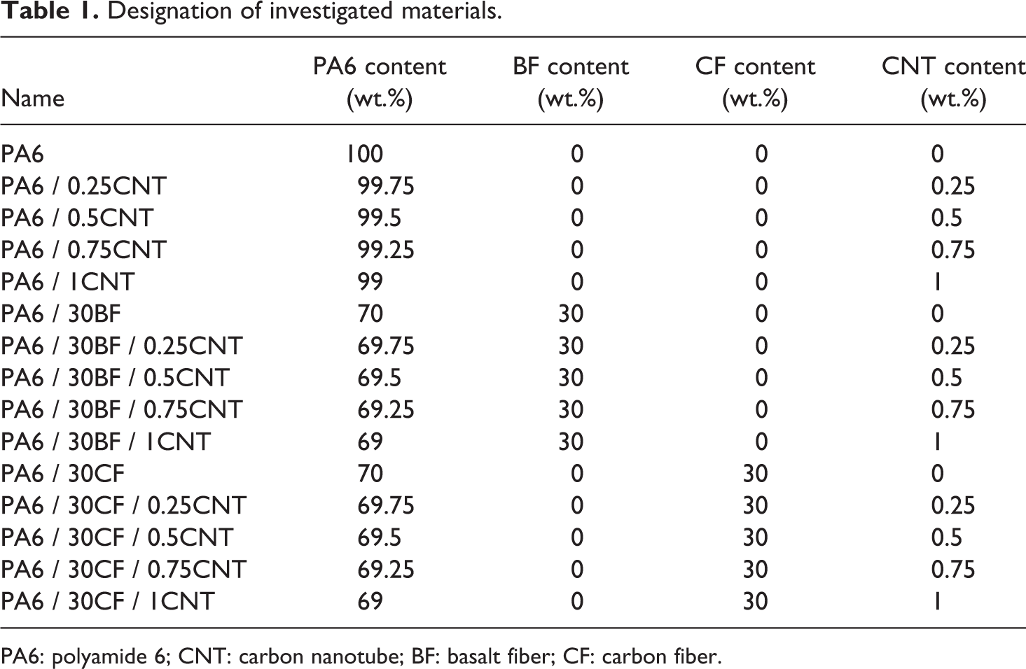
PA6: polyamide 6; CNT: carbon nanotube; BF: basalt fiber; CF: carbon fiber.
Characterization methods
Before the mechanical tests, the specimens were conditioned at 50% relative humidity at room temperature for a month, and then the temperature was set to 25°C (besides 50% relative humidity) for a further week. Tensile tests were performed on a Zwick Z020 universal testing machine (Zwick GmbH, Germany) according to EN ISO 527. The crosshead speed was 5 mm/min during tensile tests, and at least 5 specimens were tested from each material type.
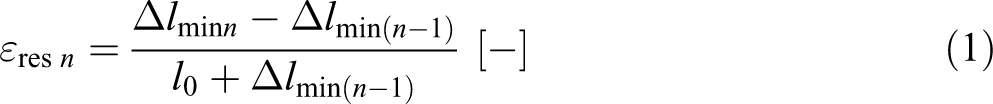
The ratio of the deformation components at different load levels was determined with special cyclic mechanical deformation tests. The conditioning process before the test was the same as in the case of tensile tests. These tests were also performed on a Zwick Z020 universal testing machine. Loading speed (both down and up directions) was set to 100 N/s. Loading force was increased by 100 N in every cycle, and after load removal, there was a 30 s relaxation time. Residual deformation εres n was determined with Equation (1), where Δl minn is the minimum elongation in the current cycle, Δl min(n−1) is the minimum elongation in the previous cycle, and l 0 is the starting length (starting grip to grip separation). The ratio of elastic recovery εrec% n was determined with Equation (2), where Δl maxn is the maximum deformation in the current cycle. These values were determined from the displacement–time diagraph (Figure 1).
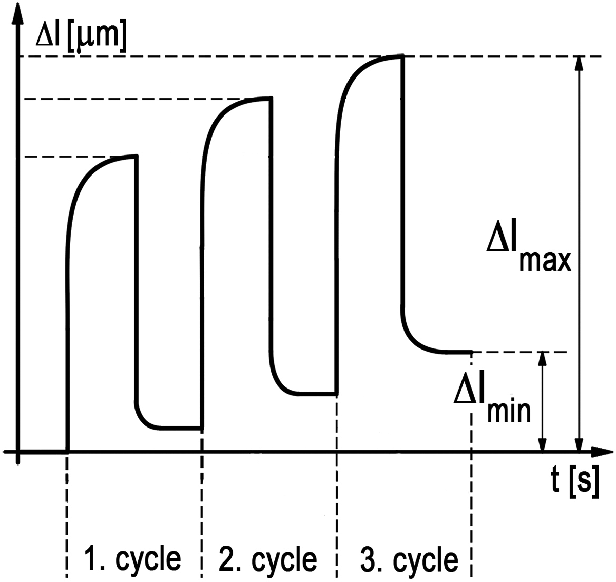
Theoretical deformation-time diagraph of a cyclic test.

Fiber length distribution was measured. Fibers were burned out from the matrix at 500°C for 1 h; then the recovered fiber length was measured with an Olympus BX51 optical microscope (Olympus Ico., Japan). Fiber length distribution was determined from the length data of ca. 1500 fibers. The fiber orientation of the samples was also investigated with this microscope: Injection-molded specimens (three per material type) were cut at a specific point (from the ordinary fracture site) and polished. On this surface the major and minor axis of the fibers were measured and the deflection from the loading axis was calculated.
The fracture surfaces of the broken tensile-tested specimens were sputtered with a thin gold layer and investigated with a Jeol 6380 LA type SEM (Jeol Ltd., Japan). Pictures were also taken from a direction perpendicular to the tensile axis to determine the protruding length of the fibers. To determine the length histogram, at least 250 fibers were measured.
The crystallinity of the materials was determined by differential scanning calorimetry (DSC; TA Instruments Q2000, USA). For the measurements, samples were cut from the middle of dumbbell specimens. The degree of crystallinity (Xc ) was calculated with the following equation:
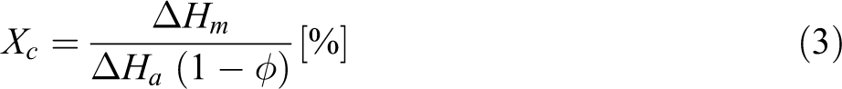
where ΔHm is the melting enthalpy, ΔHm is the average melting enthalpy of 100% crystalline PA 6, and φ is the fiber content in wt.%. The Melt Flow Index (MFI) of the materials was evaluated by using a CEAST (Italy) Modular Melt Flow 7027.000 type machine at 230°C and 2.16 kg load, according to the EN ISO 1133 standard.
Results and discussion
Conventional tensile tests
The results of conventional tensile tests can be seen in Table 2. In case of nanocomposites, no significant change was found, either in strength or in modulus values compared to the neat matrix. The presence of particles decreased both values to a small extent, that is, particles could not exert their reinforcing effect. The reason might be inadequate dispersion. Shearing in the melt during processing was not enough to break up all of the aggregates. Strain at break was reduced at only 1 wt.% CNT content, thus particles did not typically make the composite rigid. An investigation of the stress–strain curves (Figure 2) revealed major differences between the PA 6 and its composites. In the case of nanocomposites, the maximal stresses were nearly the same (as the tensile strength value shown earlier), but it was reached at higher deformation; contraction occurred later. This means nanocomposites were more ductile, which can cause higher energy absorption during deformation (Table 3). Results in the case of hybrid composites were different. The strength of composites reinforced with BF or CF increased when CNTs were added, and if the fact that nanotubes themselves decreased these values is considered, synergistic effects can be assumed. In both cases, maximal strength was experienced at 0.5 wt.% CNT content. The value of tensile strength reached 112 MPa in the case of the BF-reinforced hybrid, while the tensile strength of the composite that contained only BF was only 102 MPa. In the case of CF reinforcement, this value increased from 179 MPa to 198 MPa. This means an increase in ca. 10% in both hybrid systems. In both cases, the nanoparticle did not change the characteristic of the stress–strain curves significantly. At larger CNT content, moderate decrease was experienced; therefore, CNT content is not worth increasing further. A similar tendency could be observed when Young’s moduli of composites were examined. During the manufacturing of hybrid composites, CNT dispersion could improve it owing to the presence of fibers and that explains the improvement in mechanical properties. The value of strain at break decreased significantly compared to polyamide when BFs and CFs were applied, although this value did not decrease further when CNT was added, meaning that the effect of the microfibers was dominant. This refers to the fact that nanoparticles did not influence the fiber–matrix interaction but caused strengthening by modifying the properties of the matrix.
Tensile-mechanical and crystalline properties of the nano and basalt or carbon fiber-reinforced composites and hybrid composites.
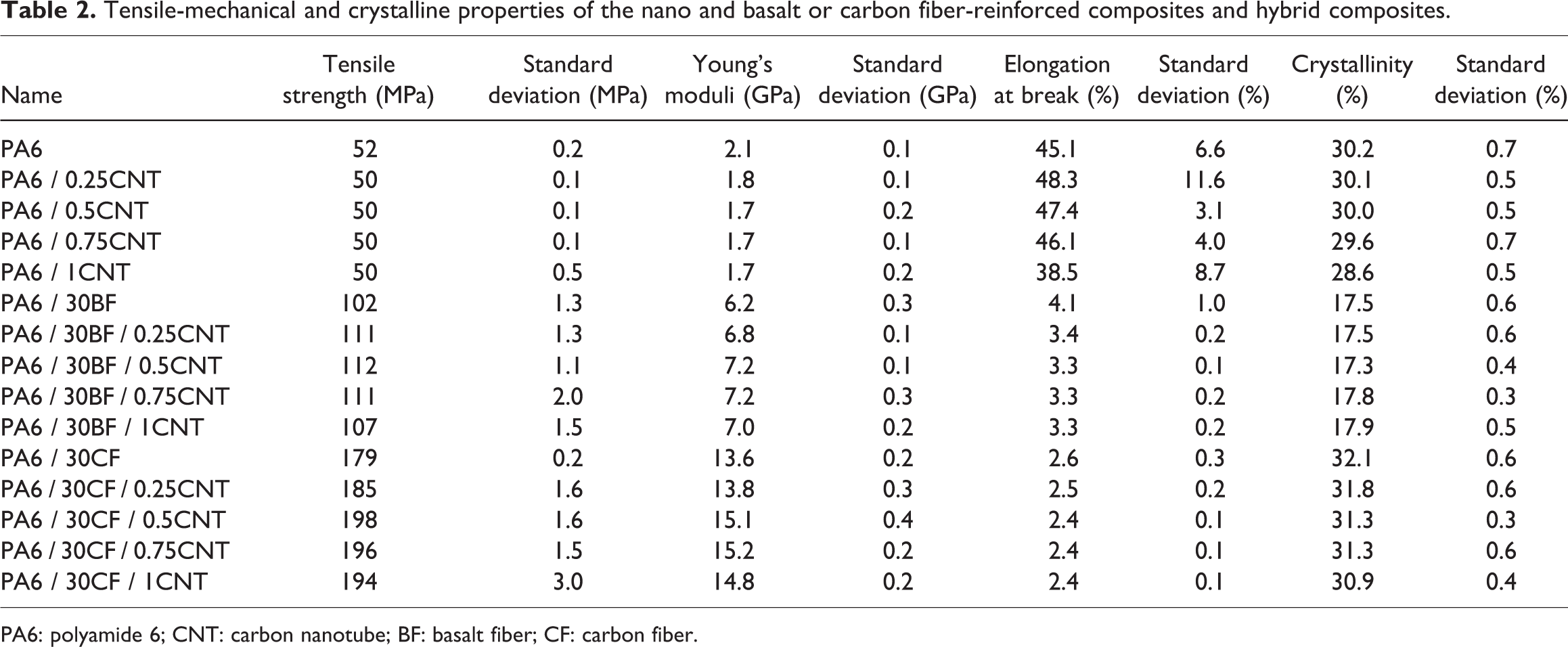
PA6: polyamide 6; CNT: carbon nanotube; BF: basalt fiber; CF: carbon fiber.
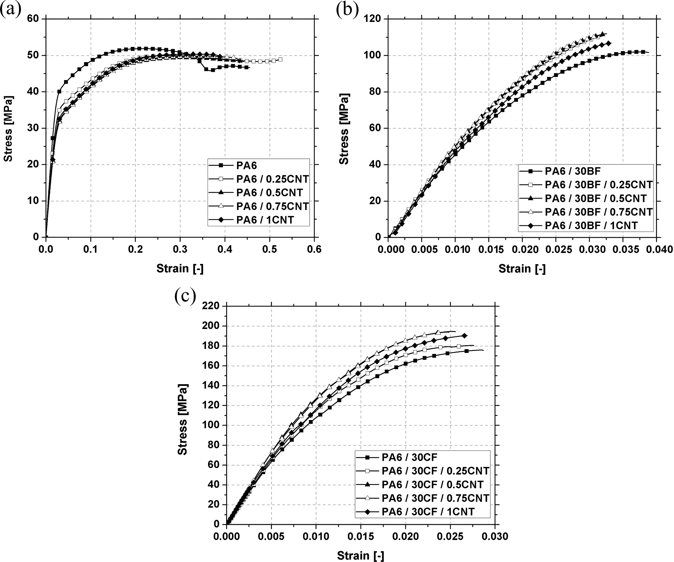
Typical stress–strain curves of polyamide and its composites: (a) polyamide and nanocomposites, (b) basalt fiber-reinforced composites and hybrids, and (c) carbon fiber-reinforced composites and hybrids.
Deformation work of the composites during tensile tests (in the case of polyamide and nanocomposites, these values represent the work till the start of cross-contraction).

PA6: polyamide 6; CNT: carbon nanotube; BF: basalt fiber; CF: carbon fiber.
Morphology of the composites
In order to examine the morphology of the produced composites, scanning electron micrographs were taken from the fracture surfaces which were formed during the tensile test, and DSC analysis was performed to reveal the crystallinity in the composites. The fracture of neat PA 6 (Figure 3A) and the fracture of nanocomposites were fully ductile, but during the examination of the fracture surfaces of nanocomposites large aggregates were observed (Figure 3B). As CNT content was increased, not necessarily larger but more aggregates were found on the surface and they were usually the starting points of failure (Figure 3C). At higher magnification, it can be seen that these aggregates are partly impregnated with the matrix (Figure 3D); therefore, these are partly dispersed and intercalated nanocomposites, but CNT is still not capable of modifying properties in a positive way. The mechanical properties of these areas significantly differ from the properties of the matrix that surrounds them, therefore aggregates act as a starting point of failure during loading and not as reinforcement.
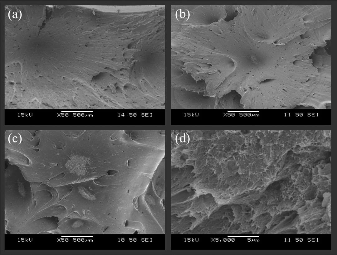
SEM micrographs of fracture surfaces: (a) PA6, (b) PA6 / 0.25CNT, (c) PA6 / 1CNT, and (d) PA6 / 0.25CNT. PA6: polyamide 6; CNT: carbon nanotube.
Figure 4 shows typical fracture surfaces of microfiber-reinforced and hybrid composites. Both micro-ductile and micro-brittle failures were found on each surface. If microfiber and hybrid composites are compared, no significant difference can be observed between the characteristic of failure, be it BF-based (Figure 4A and B) or CF-based (Figure 4D and E) composites. Based on the examination of fracture surfaces, it can be stated that fiber–matrix adhesion was adequate in the case of both fibers, also recognized in the case of hybrid composites, while nanoparticles had no impact that can be revealed by microscopy. Compared to nanocomposites, no large-size aggregates can be seen on the surface of hybrid materials, as the presence of fibers aided the decomposition of aggregates and a better dispersion of particles during processing. These well-dispersed CNTs can be seen in Figure 4(c) and (f) on the surface of BF- and CF-reinforced hybrid composites. These dispersed particles may form an adequate connection with the matrix, and therefore influence its strength properties.
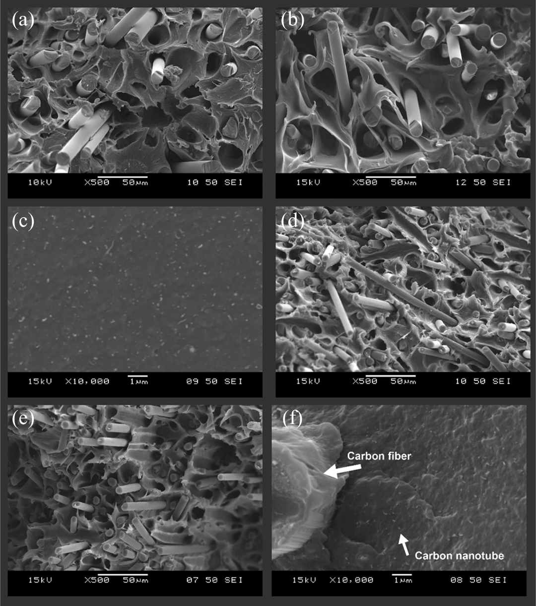
SEM micrographs of fracture surfaces: (a) PA6 / 30BF, (b) PA6 / 30BF / 0.5CNT, (c) PA6 / 30BF / 0.75CNT, (d) PA6 / 30CF, (e) PA6 / 30BF / 0.75CNT, and (f) PA6 / 30CF / 0.75CNT. PA6: polyamide 6; CNT: carbon nanotube; SEM: scanning electron microscopy; BF: basalt fiber; CF: carbon fiber.
The crystallinity of the matrix can also affect the mechanical properties of the composites 30,37,38 ; therefore, all manufactured composites were investigated by DSC. The size of CNTs is comparable with the size of the polymer chains; hence, the presence of nanoparticles may have a major impact on the morphology. 39 They can act as a nucleating agent, but on the other hand, well-dispersed particles may block the growth of crystals. The effect of these particles always depends on the properties of the surrounding system and processing parameters. The study of the nanocomposites revealed that CNT did not have a notable influence on the crystallinity of PA 6, and only a slight decrease in this value was found at higher CNT content (Table 2). The same tendencies were found in the case of both fiber-reinforced composites and their hybrids. It should be noted that in case of BF-containing composites, lower crystallinity was calculated. The better dispersion of the nanoparticles has no significant effect on the crystallinity of hybrid composites, thus the increase in the strengths and the moduli were not in strong connection with crystallinity change.
Examination of fibers
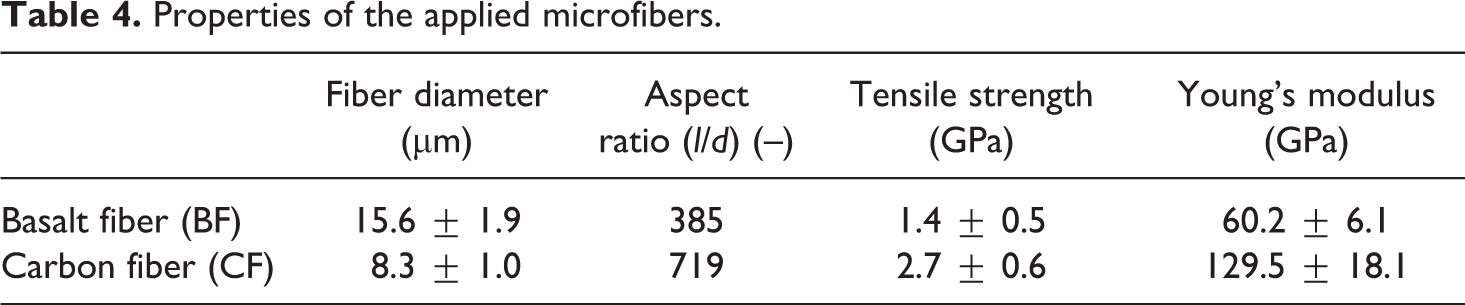
Fiber properties, fiber length formed during processing, and fiber distribution have an impact on the mechanical properties of composites. The diameter of the BF applied was double that of the CFs, which is why the initial aspect ratio of BFs was nearly half that of CFs (Table 4). The tensile strength and modulus of CF are also twice those of BF. The difference between the densities caused a higher volume ratio of CF, and this higher volume ratio and higher modulus caused the higher strength and modulus of the CF composite.
Properties of the applied microfibers.
Besides processing parameters, added CNT may also affect fiber length distribution, and owing to their large specific surface, they may increase the viscosity of the melt and this way increase shearing in the melt. Melt Flow Index (MFI) investigations (Figure 5) revealed that CNT highly decreased the flowability of PA 6, but in connection with further results, this increased shearing was not enough to break up the aggregates. Microfibers had a significant effect on MFI. BF halved its value, while the MFI of CF composites was 17.1 g/10 min. Adding CNT to these systems further decreased this value. On one hand, this aids aggregate decomposition, but on the other hand, it may result in fiber breakage.
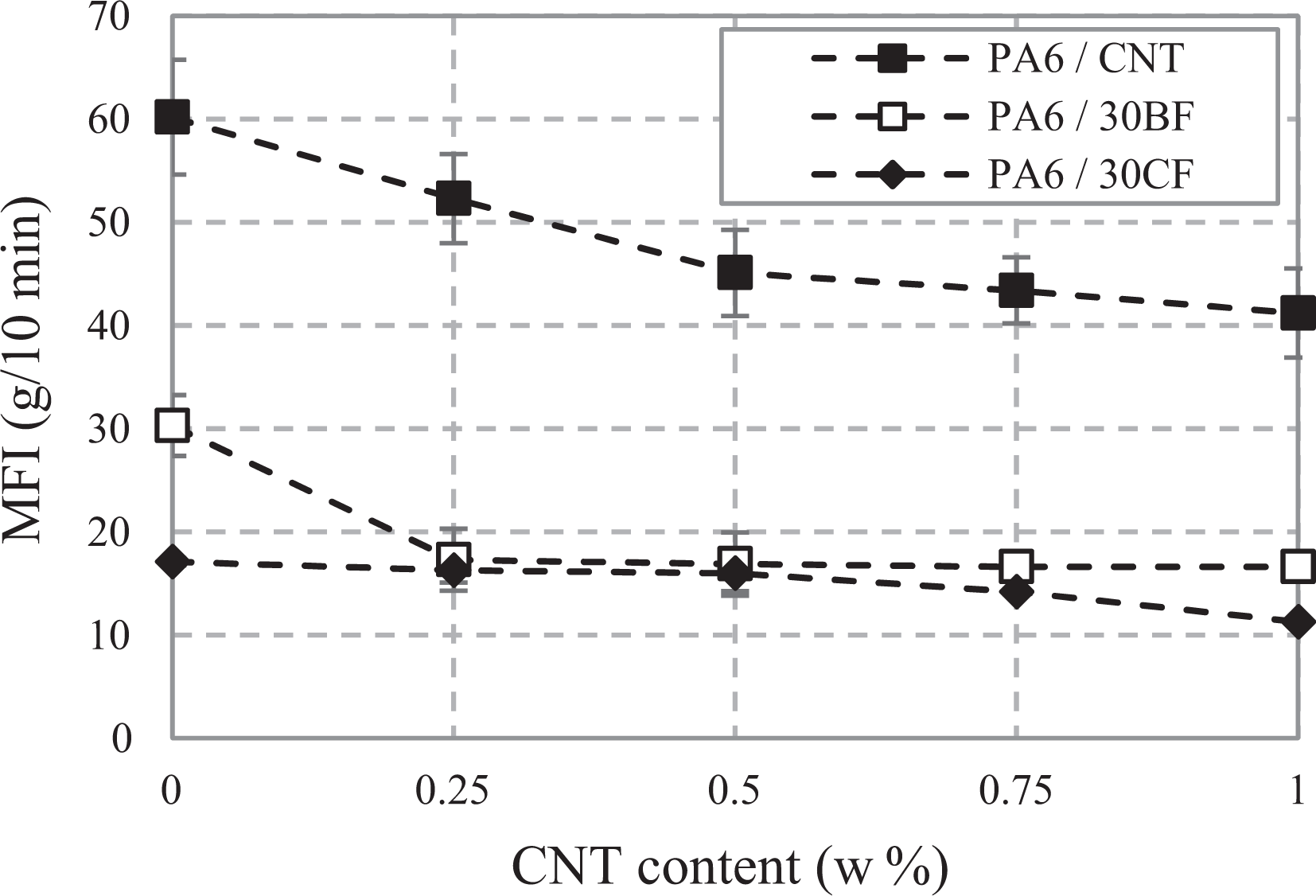
Melt flow index (MFI) of nano and hybrid composites.
The length distribution of fibers was approximated with a log-normal function. 40 In the case of BF composites, it can be seen that if CNT content increased, the amount of shorter fibers also increased (Figure 6). This could be the reason why in the case of larger CNT content strength decreases. A reduction in the arithmetical mean of the fitted log-normal function also confirms this phenomenon. Thanks to the fiber length decrement, the aspect ratio of the fibers also decreased. The aspect ratios changed from 385 to 14.5 in the case of the BF composite, and it decreased to 7.9 at 1 wt.% CNT content.
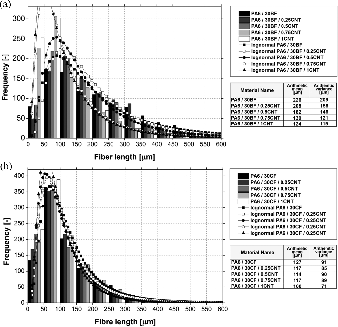
Measured length histogram of (a) basalt and (b) carbon fibers.
Based on the analysis of the log-normal distribution fitted on the frequency function, it can be stated that CF suffered more breakage than BF during processing (the initial fiber length was 6 mm in both cases). A CNT content of 0.25% decreased fiber length further, but the extent was smaller than in case of BF composites. In spite of higher breakage, the aspect ratio of CFs was slightly higher (∼15.3) than that of BFs. A slightly higher aspect ratio and higher mechanical strength also explains the observed higher strength of CF composites. When CNT content was increased, up to a value of 0.75%, fiber length did not change significantly, and then at 1% CNT content a smaller decrease occurred (Figure 6). It means that the presence of nanotubes had only a minor impact on fiber breakage that occurred during composite manufacturing, while in the case of BFs, this influence was significant.
From the point of view of mechanical properties, fiber orientation is also very important. Strength and modulus are maximal when the fibers are aligned well with the axis of the load. During injection molding, fiber orientation may be different in different regions. The presence of CNT decreased the MFI of hybrid composites, which means higher apparent viscosity. This change can also change the fiber orientation of the composites, and during processing this has a major effect. This is why the dimensions of the skin core layer of the injection molded specimens also changes. For this reason, fiber orientation was also determined for the composites. On the surfaces, a well-described skin core layer was not identified; the orientation of the fibers was homogenous. The tests showed that the decreased MFI had no major impact on the fiber orientation of the composites; fiber orientation distribution is similar in every composite, that is why its effect on strength can be excluded (Figure 7). In case of CFs, the frequency showed higher deviation. This phenomenon can be explained with shorter fiber length; these shorter fibers are more sensitive to a change in melt flow direction and inhomogeneity.
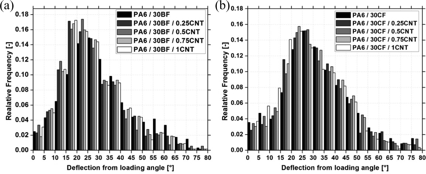
The deflection of (a) basalt and (b) carbon fibers from the loading axis in the injection molded specimens.
Nanoparticles may appear in the fiber–matrix boundary phase during processing and they may improve the connection of the two phases and this way increase composite strength. Several methods to determine interfacial adhesion exist, the most significant and widespread of which is the microbond test. The application of this method for the determination of interfacial connection in thermoplastic hybrid composites is quite difficult. During the preparation of samples for the test, conditions are very different from those during processing (pressure and shearing), and the dispersion of the particles is also not ensured. The length of protruding fibers also reflects fiber–matrix connection, where this connection can be studied. 41 –43 Protruding fibers were examined on the fracture surfaces formed during tensile tests. Based on the examinations, it can be stated that the distribution of the length of protruding fibers is quite similar (Figure 8), and the expected values of distributions approximated with the log-normal function decreased slightly when CNT content was increased in the case of the BF composite, while in the case of the CF composite, they remained almost unchanged. Taking into consideration that a similar tendency can be observed in the case of fiber length distribution, it can be stated that CNTs did not improve fiber–matrix adhesion but caused changes in the mechanical properties by changing the properties of the matrix, as also expected after the results of tensile tests.
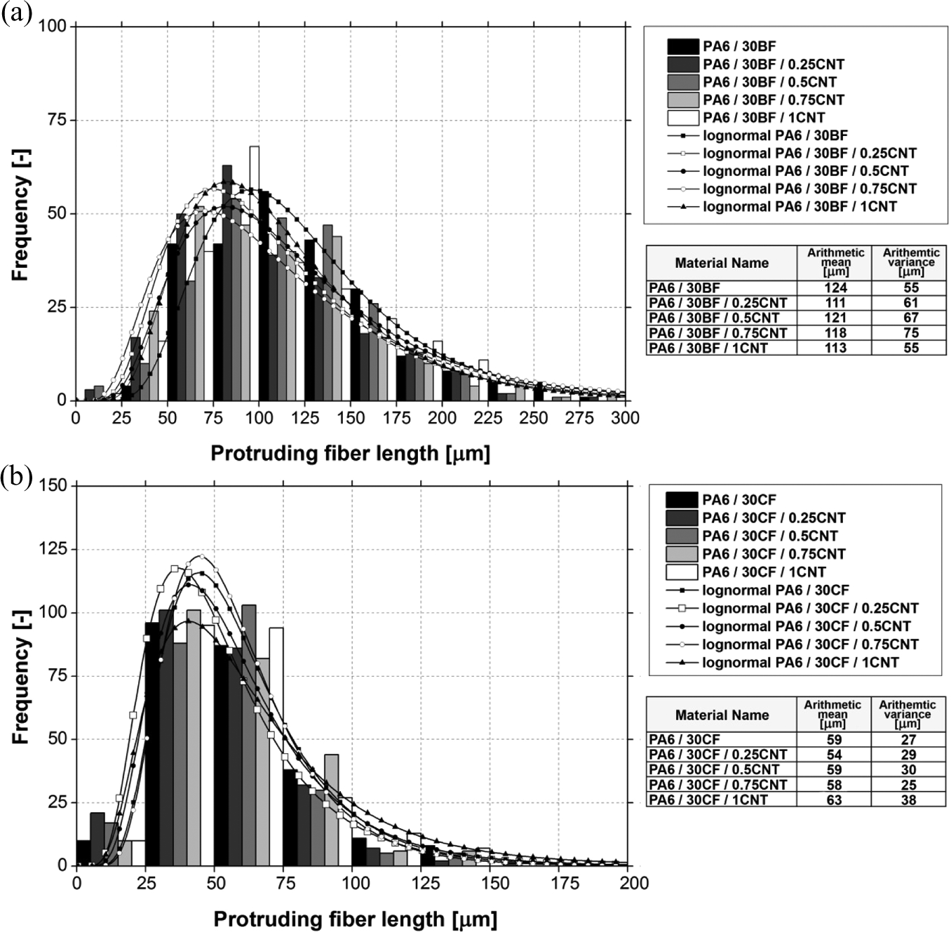
Measured length histogram of protruding (a) basalt and (b) carbon fibers.
Cyclic tests
Since the matrix is thermoplastic, in the case of mechanical loading, elastic and plastic deformation both occur due to its viscoelastic behavior. Reinforcing materials typically decrease the extent of residual deformation and this way creeping and cyclic creeping (fatigue) as well. The quantity and ratio of residual deformation and elastic recovery are properties that depend on the loading applied, and their change can be analyzed with the help of cyclic tests carried out in previous studies. 44,45 Nanoparticle size is comparable to the dimensions of the molecules in the polymer and this means other effects regarding reinforcing than in the case of conventional composites. On one hand, molecules may surround nanoparticles, and on the other hand nanoparticles may form bridges among the molecules. 17,46 This molecular level interaction may change the characteristic of polymer behavior and that influences viscoelastic properties, more exactly the ratio of plastic and elastic deformation components. 47,48
Although hybrids are complex systems, it was already discussed earlier that the impact of nanotubes is not related to the improvement in fiber–matrix adhesion; therefore, the examination of these deformation components as a function of nanotube content may provide information on the role of nanotubes in the matrix. Based on the results of cyclic tests with increasing loading, it can be stated that in composites that contain CNT, residual deformation decreases and the extent of elastic recovery increases owing to the nanoparticles, although the strength of the composite does not change (Figure 9). It means that nanoparticles decrease residual deformation while the ultimate strength properties do not change significantly. The explanation of this phenomenon is that nondispersed or only slightly dispersed particles inhibit the mobility of chains; they make their relative movement more difficult.
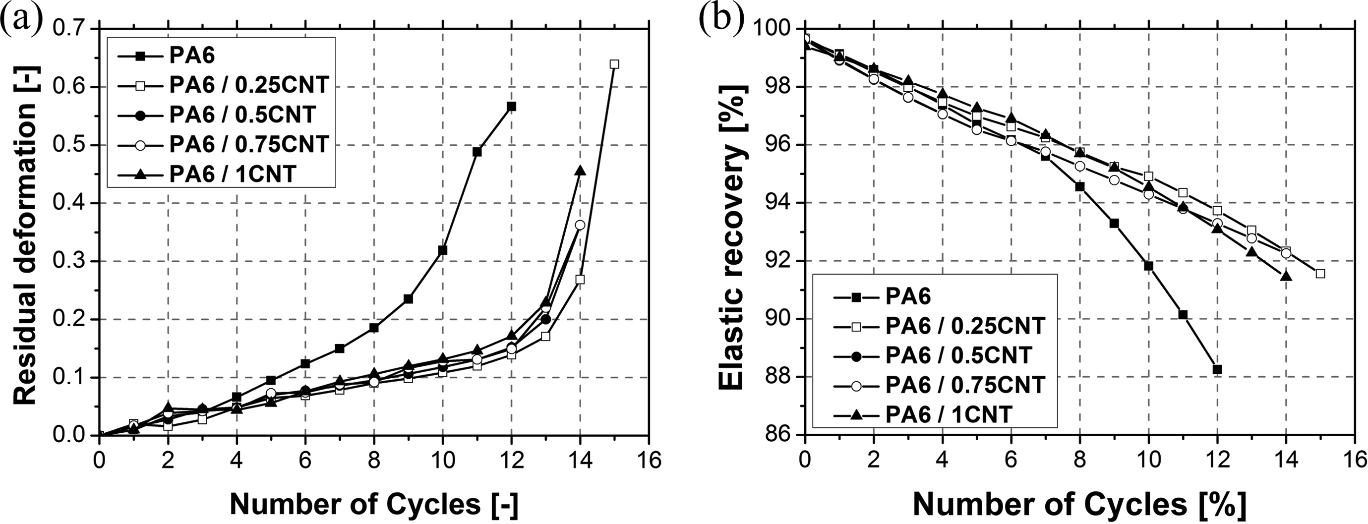
(a) Nanocomposites residual deformation and (b) rate of elastic recovery at different load levels (cycle number multiplied with 100 shows the loading force in N).
The application of BF results in a significant decrease in the residual deformation of the material, since stress distribution is more homogeneous in the composite and much of the loading is taken by the fibers (Figure 10). As a result, in the case of nanocomposites, a stress of 17.5 MPa is enough to reach a residual deformation of 10%, while in the case of BFs, a stress of 50 MPa is necessary for the same residual deformation. Hybridization further decreases residual deformation, and increases elastic recovery (Figure 11). Well-dispersed particles homogenize stress in composites and take up some of it, and decrease the mobility of chains, due to adhesion and looping through nanotubes (Figure 12). This impact can be experienced until 0.75 wt.% CNT content, above which the extent of residual deformation increases again. At high CNT content, their dispersion may become inhomogeneous, and therefore regions with different mechanical properties may form in the composite and that results in a slight worsening of composite properties.
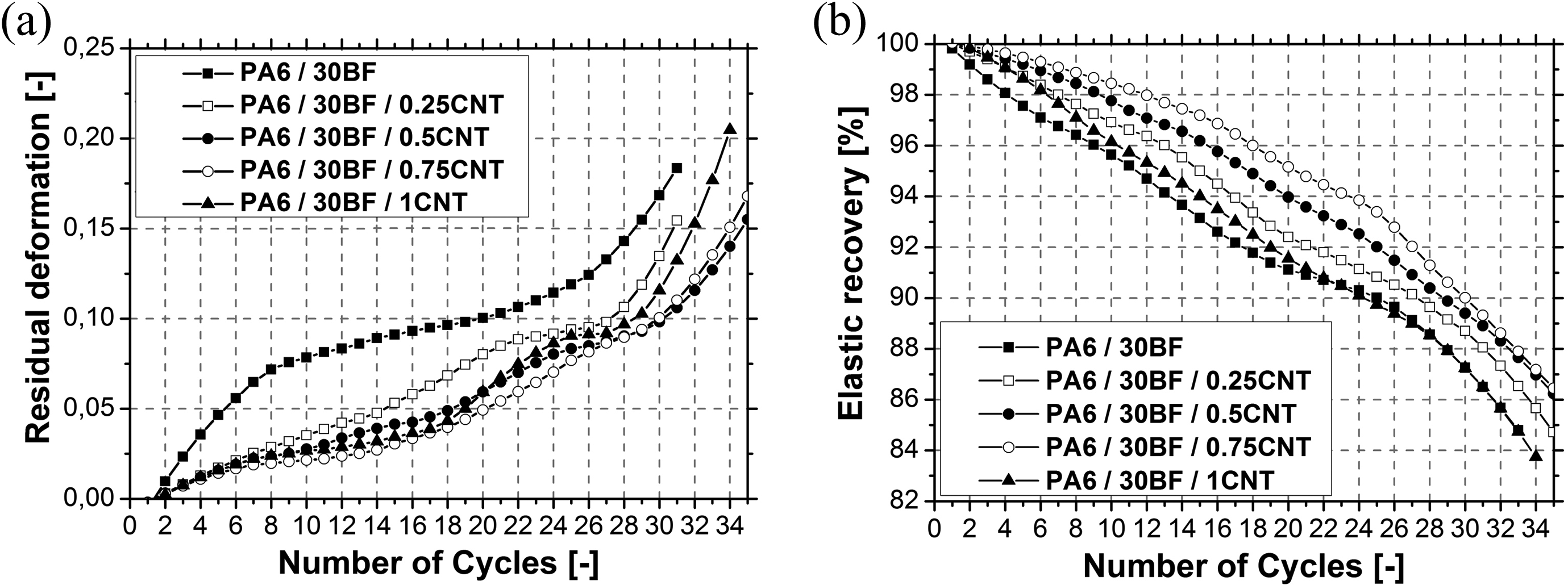
(a) Basalt fiber-reinforced composites and hybrid composites residual deformation and (b) rate of elastic recovery at different load levels (cycle number multiplied with 100 shows the loading force in N).
(a) Carbon fiber-reinforced composites and hybrid composites residual deformation and (b) rate of elastic recovery at different load levels (cycle number multiplied with 100 shows the loading force in N).
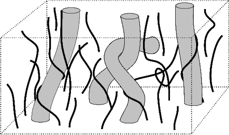
Molecular interaction (looping and web forming) between carbon nanotube (gray) and polymeric chain (black).
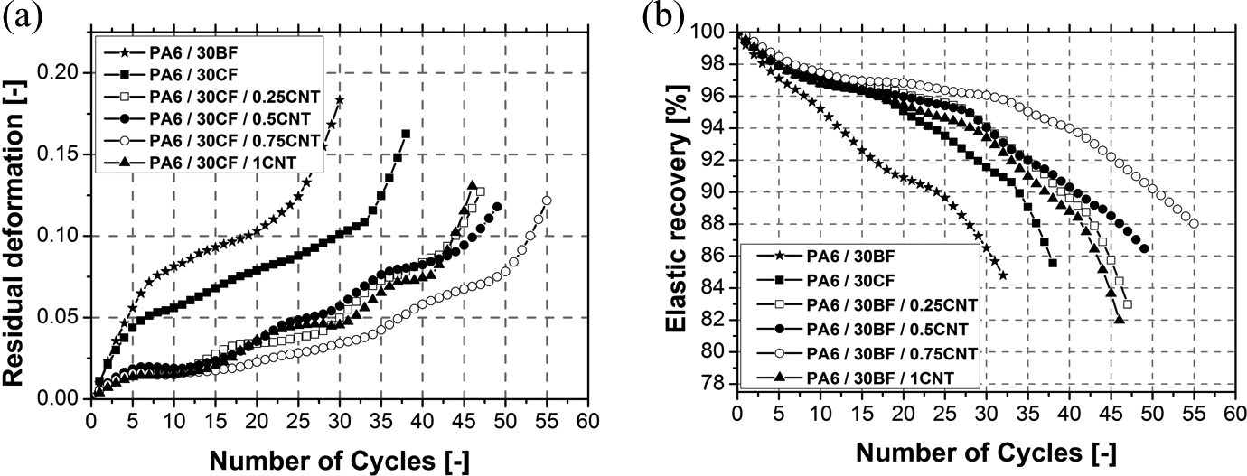
In the case of CFs, the residual deformation of composites decreased to a small extent compared to BF composites (Figure 11). This is primarily due to the higher strength and modulus of reinforcing fibers. As a result of CNT content, the hybrid composite behaved in a more elastic way; the extent of residual deformation decreased. At small load levels, the residual deformation of the two systems were nearly the same; however, at higher load levels the residual deformation of hybrids remained smaller, meaning that in the case of higher loading for a longer time, the application of CFs and CNTs is more advantageous. Among the carbon-based hybrid composites, the composite with 0.75 wt.% CNT performed the best.
Conclusion
Basalt and CF-based PA 6-matrix composites with CNT were examined in our present research. Mechanical tests revealed that the strength and modulus of composites increased as a result of hybridization, while the material did not become more rigid. Scanning electron micrographs revealed the dispersion of particles improved in hybrid systems compared to nanocomposites. Therefore, in the case of melt processes, particle dispersion improves owing to the presence of fibers and that results in the improvement in mechanical properties as well. Besides the improvement in classical mechanical properties, both nano- and hybrid composites behaved in a more elastic way; their residual deformation decreased. Therefore, parts made from hybrid materials can withstand higher loads. Furthermore, less material is necessary to bear the same load and therefore parts can be made with thinner walls, which allows weight reduction, a very important aspect in engineering practice. The changes in deformation components can be explained with the stress homogenization effect of the nanoparticles in the matrix and their ability to decrease chain mobility.
Footnotes
Acknowledgements
This paper was supported by the János Bolyai Research Scholarship of the Hungarian Academy of Sciences.
Declaration of Conflicting Interests
The author(s) declared no potential conflicts of interest with respect to the research, authorship, and/or publication of this article.
Funding
This research was supported by the Hungarian Research Fund (OTKA PD105564).