
Abstract
Carbon fiber–reinforced thermoplastic (CFRTP) composites are gaining popularity in the manufacturing industry of lightweight automobiles. Common composite defects (e.g. voids and delamination) often occur inside CFRTP composites due to their inappropriate manufacturing process and long-term service. In this study, an instrumented tapping system was designed to evaluate the health condition of CFRTP composites by controlling the input force and velocity. The effective mathematical expressions of the contact duration and amplitude of the interactive force were derived to quantify the local stiffness of the tapping area. The amplitude of the interactive force was introduced innovatively as a significant evaluation parameter for a non-closed force–time curve with the time axis due to the influence of constraint condition and coupling effect of the modal shapes excited during tapping. The contact duration of the interactive force over the defective region was longer than that over the sound region. The amplitude of the interactive force applied on the defective area was observed to be lower than that on the sound area. In addition, the applicability and sensitivity of the amplitude of the interactive force was also investigated by changing the dimensions and locations of defects.
Introduction
Carbon fiber–reinforced thermosetting resin (CFRTS) composites are gaining widespread attention in the aerospace industry due to their high specific moduli, specific strengths, and damage tolerances. 1 –3 Carbon fiber–reinforced thermoplastic (CFRTP) composites have remarkable advantages regarding manufacturing cycle time and recyclability in comparison with CFRTS composites. 4 –7 Meanwhile, discontinuous CFRTP composites will be more suitable for the manufacture of complicated structures because of their excellent molding performance. 8 –12 Therefore, two types of discontinuous CFRTP composites, chopped carbon fiber tape–reinforced thermoplastic (CTT) and carbon fiber mat–reinforced thermoplastic (CMT), were developed specifically to achieve high-volume, lightweight auto production in a current Japanese national project. 13,14
Voids, cracks, and delamination are common flaws inside CFRTP composites that are caused by inappropriate manufacture and use. 15 –23 Ultrasonic testing has been widely applied in the aerospace industry but is not suitable to be extensively utilized to conduct a general check for the inspection of CFRTP components in the automotive industry. This is due to the high inspection cost. 24 –26 However, a convenient, accessible tapping test can fill the requirement of nondestructive inspection for the automotive industry. 27,28 Cawley performed an in-depth study on various types of low-frequency vibration inspection methods including global and local methods. 29,30 The global method uses natural frequency measurements to check the health condition of composite structures but has had low sensitivity and accuracy. 31,32 The local method is focused on a coin-tap test. 33 This is a simple defect detection model that was proposed to describe the identification mechanism. 34,35 Wu explored the fundamental principles underlying the coin-tap test and analyzed the nonlinear relationship between the impact and the force–time history of the test. 36 Kim characterized the relationship between the contact force history and the defect location. 37 In addition, many commercially available products (e.g. the computer-aided tap tester developed by Advanced Structural Imaging Inc, Ames, Iowa, USA.) have been used to inspect composite sandwich structures for disbonds and core damages. However, these tests are not always effective at evaluating the health condition of the CFRTP composites, such as CMT and CTT. 38 –41 Nearly, all the tests focus solely on the contact duration of the tapping process and neglect the amplitude of the interactive force, which should be the other significant parameter when the tapping velocity is controlled.
In this article, a tapping system was designed to detect the CFRTP defects such as voids and delamination inside CMT and CTT. The tapping velocity and force of this system were controlled precisely. The effective mathematical expressions regarding the amplitude of the interactive force were derived to quantitatively evaluate the local stiffness of CMT and CTT. In addition to the contact duration, the feasibility and sensitivity studies of using the amplitude of the interactive force to evaluate the CFRTP composites were also investigated.
Materials and experiments
Preparation of the defect-free CTT and CMT materials
Two types of raw CTT (i.e. CTT-A and CTT-B) were investigated in this study. The dimension of the chopped tapes constituting CTT-A and CTT-B was 18.0 × 5.0 × 0.044 mm3 and 18.0 × 5.0 × 0.093 mm3, respectively. Three kinds of raw CMT with different carbon fiber volume fractions (10%, 20%, and 30%) were prepared, separately. The raw CTT-B and CMT were provided by the Industrial Technology Center of Fukui Prefecture (Fukui-shi, Japan) and Toray Industries, Inc. (Tokyo, Japan), respectively. The CMT was manufactured by compressing randomly dispersed fibers (6 mm in length) in an in-plane. The CTT was manufactured by compressing innumerable randomly oriented carbon fiber tapes (Figure 1(a)). The specific process parameters used for the CTT molding process are illustrated in detail in Figure 1(b). The surface graphs of CMT (Figure 2(a)) and CTT (Figure 3(a)) were obtained by observing the CMT and CTT samples using the Hirox KH-8700 (Tokyo, Japan) digital microscope. The micrographs of CMT (Figure 2(b)) and CTT (Figure 3(b)) were obtained by observing the CMT and CTT samples using the three-dimensional (3D) X-ray microscopic CT scanner (3D X-ray scan system TDM1000-II from Yamato Scientific Co., Tokyo, Japan).
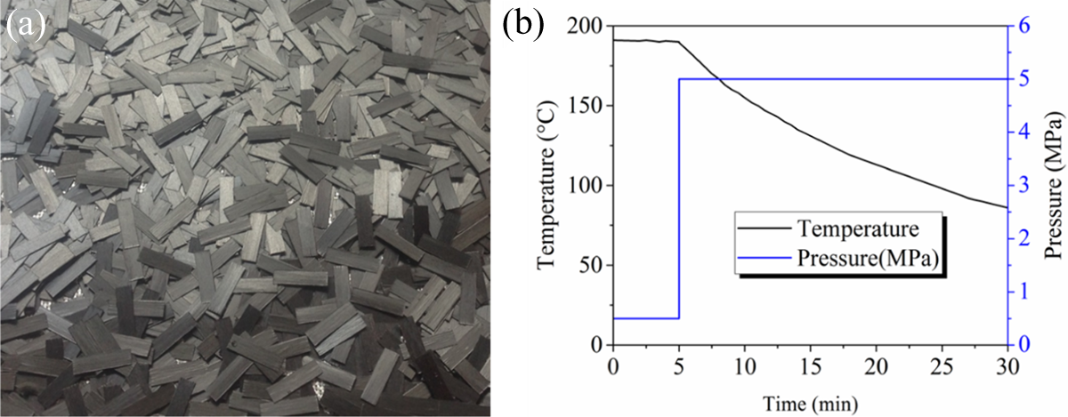
Manufacturing of the CTT: (a) dispersion of tapes and (b) molding process. CTT: carbon fiber tape–reinforced thermoplastic.
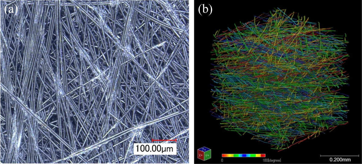
CMT (Vf 20%): (a) surface observation and (b) representative volume element. 42 CMT: carbon fiber mat–reinforced thermoplastic.
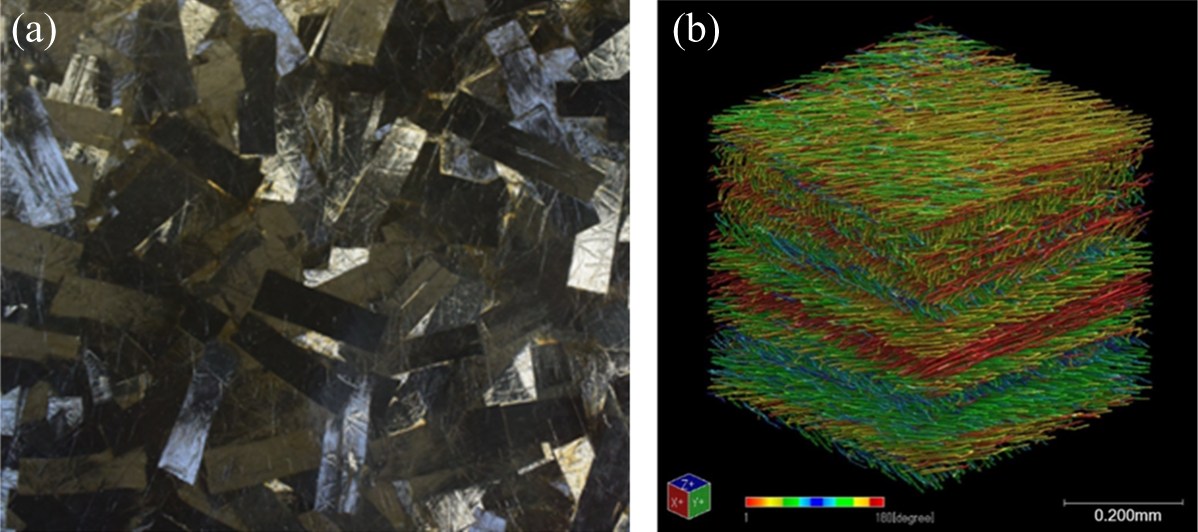
CTT: (a) surface observation and (b) representative volume element. 42 CTT: carbon fiber tape–reinforced thermoplastic.
Fabrication of the CTT and CMT specimens with defects
An overview of the defective specimens is presented in Table 1. To create voids in the CTT-A and the CMT specimens, the molding pressure was reduced on the specimens. To create delamination in the CTT-B specimens, the non-sticky Teflon films were inserted into the specimens before the molding process. To investigate the identification ability of this tapping system for the areas with different resin contents, defect-free CMT specimens with three different carbon fiber volume fractions (10%, 20%, and 30%) were molded under the same pressure, separately. The fiber contents of the defective CTT and CMT specimens depend on the raw materials which were used to mold the specimens by hot pressing. The void contents inside the specimens could be determined (see ASTM D2734-16). Detailed information about the defective specimens is listed in Tables 1 to 3.
Defective specimens’ information.
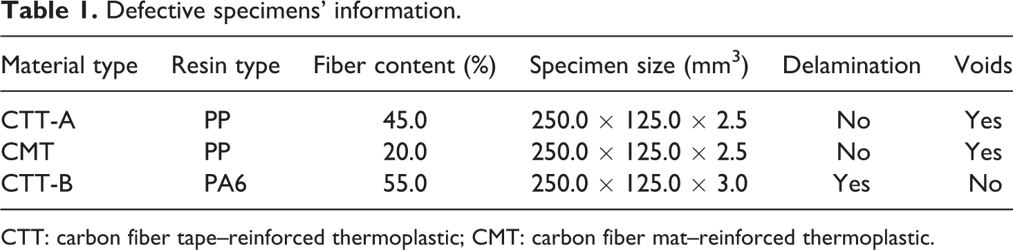
CTT: carbon fiber tape–reinforced thermoplastic; CMT: carbon fiber mat–reinforced thermoplastic.
Defective specimens with different void volume fractions.
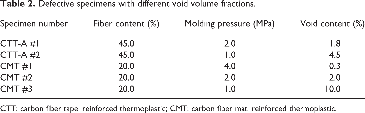
CTT: carbon fiber tape–reinforced thermoplastic; CMT: carbon fiber mat–reinforced thermoplastic.
Delamination information of CTT-B specimens.
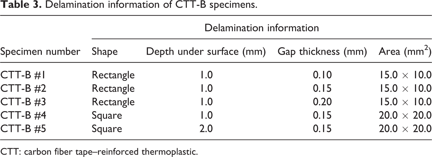
CTT: carbon fiber tape–reinforced thermoplastic.
Experimental setup
The tapping equipment of the system is shown in Figure 4(a). The mass of the tapping hammer can be controlled by adding the weight accessories, and the dropping velocity of the hammer can also be controlled by adjusting the height of the supporting device. One force transducer (PCB Model 086E80, New York, USA) with high sensitivity is built in the tip of the instrumented hammer. The hammer is connected to the portable Noise & Vibration Analyser (TOYO Corporation Model OR34, Tokyo, Japan) which is used to collect and analyze the force signal. Then, the contact duration and amplitude of the force profile are determined by the Noise & Vibration Analyser. The fixture with a rectangular hole is presented in Figure 4(b). Two sides of the specimen are constrained by the four fixed heads. Tapping point is located at the center of the fixed rectangular area.
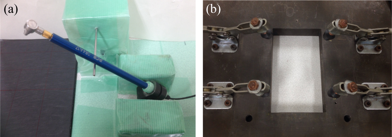
(a) Instrumented hammer and (b) fixture with rectangular hole (150 × 80 mm2).
Theoretical analysis
The model for the health condition evaluation for the CFRTP materials is illustrated in Figure 5. The stiffness kd in the delaminated area is significantly lower than the stiffness kc in the sound area. 35 Hence, the equivalent stiffness ke of the two springs in series is lower than the stiffness of either individually. A damped simple harmonic motion (DSHM) system (Figure 6) is adopted to describe the inspection behavior. This is due to the existence of dampening effects. Equation (1) is proposed to describe the DSHM model

where m is the mass of the tapping block, x the displacement of the tapping block during contact, t the time, c the damping of the local tapping point, k the stiffness of the local tapping point, g the gravitational acceleration, and θ the angle between the horizontal plane and the tapping surface.
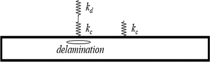
Schematic diagram of the defect model.
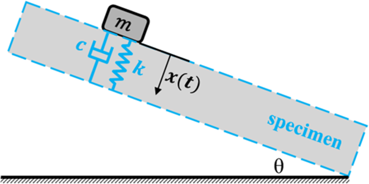
Schematic DSHM of the tapping system. DSHM: damped simple harmonic motion.
Initial conditions of the motion equation (1) are listed below


where v0 is the initial tapping velocity of the tapping block.
An expression for the displacement of the local tapping point can be obtained

where
Therefore, the interactive force between the tapping block and the tapping point can be derived
where
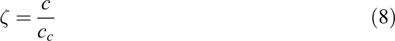
For the DSHM system described in Figure 6, the damping ratio ζ is defined as the ratio of the damping coefficient c in equation (1) to the critical damping coefficient cc

Then, equation (5) can be reduced to
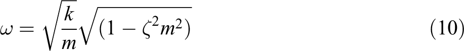
Generally, the damping ratio ζ of the CFRTP with excellent damping properties is lower than 0.1, 43 and the mass of the tapping block is approximately 10 g. Therefore, equations (10) and (6) can be reduced further to
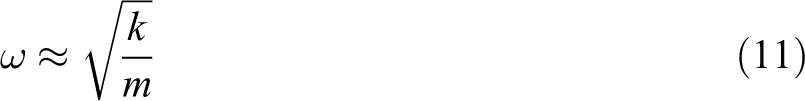
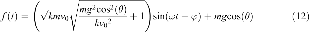
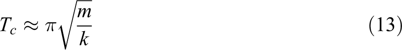
The local stiffness k of the tapping area is very high (about 106 N/m). The tapping velocity is approximately 0.5 m/s, and the force–time curve (see equation (12)) is theoretically a strict sine wave. Therefore, the contact duration Tc and the force amplitude Fmax can be reduced to

As revealed in equations (13) and (14), the contact duration would be extended, and the amplitude of the force would decrease over the defective area due to the loss in local stiffness (Figure 7(a)). In fact, the force–time curve is not a strict sine curve, that is, the latter part of the interactive force profile decreases slowly (Figure 7(b)) and often does not meet with time axis (Figure 7(c)) due to the influence of the specific boundary condition and the coupling effect of the vibration modes. Accordingly, the contact duration often cannot be measured accurately, while the amplitude of the interactive force profile can be easily determined. Therefore, the amplitude should be the other useful parameter to evaluate the health condition of CFRTP.
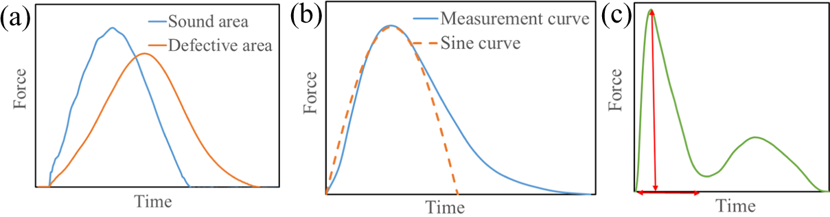
(a) Force–time curves over different areas; (b) comparison between the general force–time curve and the sine curve; and (c) force–time curve analyzed in this study.
Results and discussions
Verification of the evaluating parameters
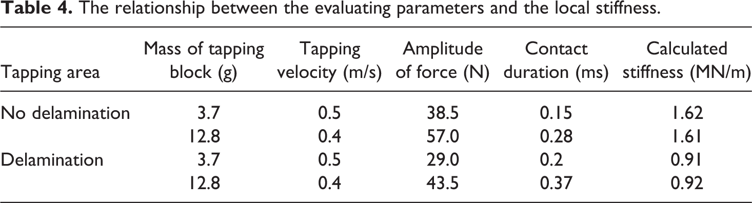
To verify the validation of equations (13) and (14), the sound area and delaminated area were tested by adjusting the mass and velocity of the tapping block. For the same tapping area and constraint condition, the contact durations are independent of the tapping velocities, while the amplitudes of the force profiles are dependent on the tapping velocities (Figure 8). Even using the different sets of tapping block and velocity listed in Table 4, for example, (3.7 g, 0.5 m/s) and (12.8 g, 0.4 m/s), the stiffness for sound area and delaminated area can be calculated using equations (13) and (14), respectively. For the fixed set of tapping block and velocity, the sound area and delaminated area have significant different evaluating parameters (amplitude of force and contact duration). In other words, the amplitude of force and contact duration are valid parameters which can be used to evaluate the stiffness of CFRTP. No matter the amplitude of force or contact duration, both parameters can be used to determine the local stiffness of CFRTP when the contact duration can be measured during the test.
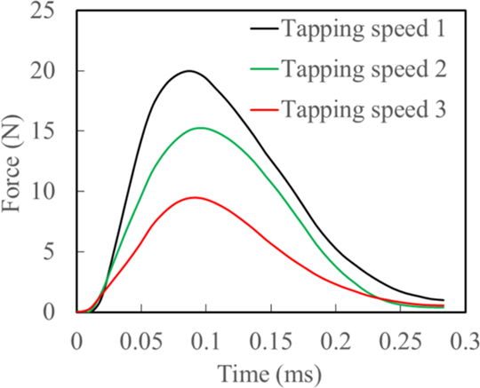
The influence of the tapping velocity on force profile.
The relationship between the evaluating parameters and the local stiffness.
CMT specimens were constrained along the direction perpendicular to the surface by three different fixtures (Figure 4(b)). Tapping points were located at the center of these holes. As illustrated in Figure 9, for the same tapping area, the force profile is dependent on the specific constraint condition. The first waves of these force profiles have nearly the same shapes. While the contact durations of the blue and red curves could not be measured due to unclosed curves between the time axis and the force profile. In this case, the amplitude of the interactive force becomes an important and unique parameter that is used to evaluate the health condition of the specimen.
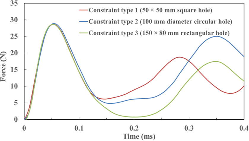
The influence of the constraint condition on the force profile.
Delamination evaluation
Like the unidirectional continuous fiber laminate, CTT is fabricated out of large amounts of long chopped unidirectional prepreg tapes. Therefore, delamination is the most common defect during manufacture and in-service. As shown in Figures 10 and 11, the force–time curves of the sound areas are set as the standard, and all the force values of the defective areas are normalized with respect to those of the sound areas. The amplitudes of the force profiles are observed to reduce remarkably with the increasing delamination gap thicknesses, whereas the contact durations are extended at the same time. Meanwhile, the exact contact durations are often difficult to be accurately measured (Figure 11). Due to the limitation of the tapping method, it is also difficult to identify distinctly any delamination that is deeper than 2 mm below the surface. The thickness of the CTT used to manufacture panels is usually less than 4 mm. Accordingly, this simple and smart tapping system is suitable for checking the CTT for delamination.
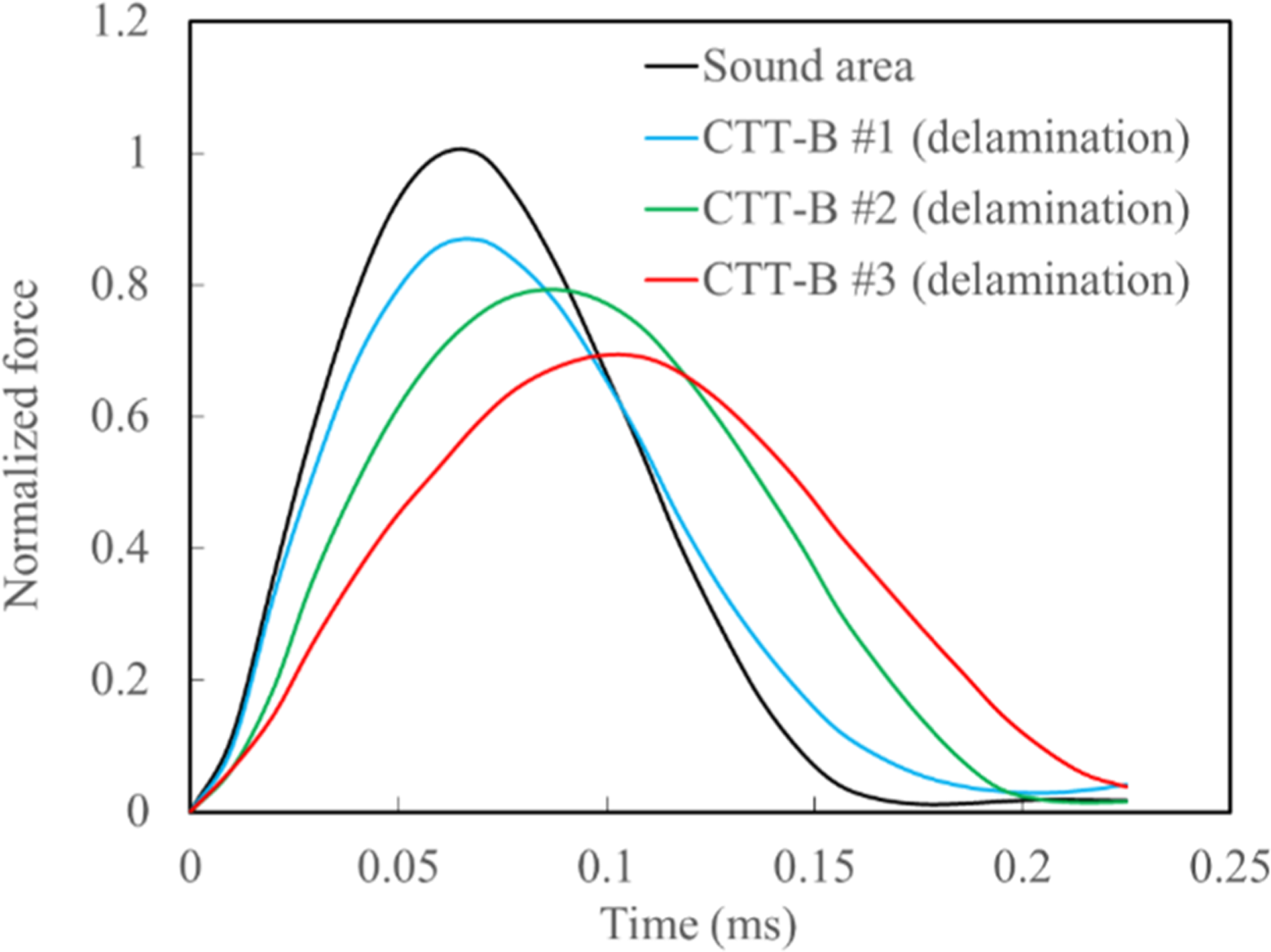
Evaluation of the delaminations with different gap thicknesses.
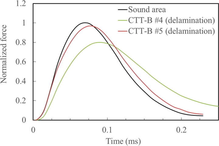
Evaluation of the delaminations with different depths under the surface.
Voids evaluation
Void is the other common defect for CMT and CTT due to an inappropriate molding process, such as lower molding pressure. As shown in Figure 12, the amplitude of the interactive force is more easily identified than those of contact durations. In this study, the contact duration alone cannot be adopted to identify the voids, while the void content is lower than 2.0%. Similarly, the contact duration of the first wave could not be acquired due to the low stiffness of the tapping area. Therefore, the amplitudes of the force profiles are proved to be an important parameter when the contact durations are not available (Figure 13).
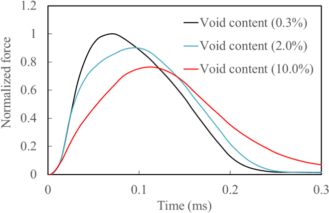
Void evaluation for specimens: CMT #1, CMT #2, and CMT #3. CMT: carbon fiber mat–reinforced thermoplastic.
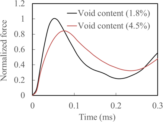
Void evaluation for specimens: CTT-A #1 and CTT-A #2. CTT: carbon fiber tape–reinforced thermoplastic.
Resin content evaluation
To investigate the identification ability of this tapping system for the areas with different resin contents, the force–time curves of CMT (Vf 20%) and CMT (Vf 10%) specimens are compared with that of CMT (Vf 30%) specimen which is regarded as a standard (Figure 14). The contact duration could not be used as a precise parameter when the fiber volume fractions are not significantly different from each other. However, the amplitude of interactive force could distinguish the difference in fiber content. In many practical tests, the amplitude of interactive force plays a more important role than the contact duration.
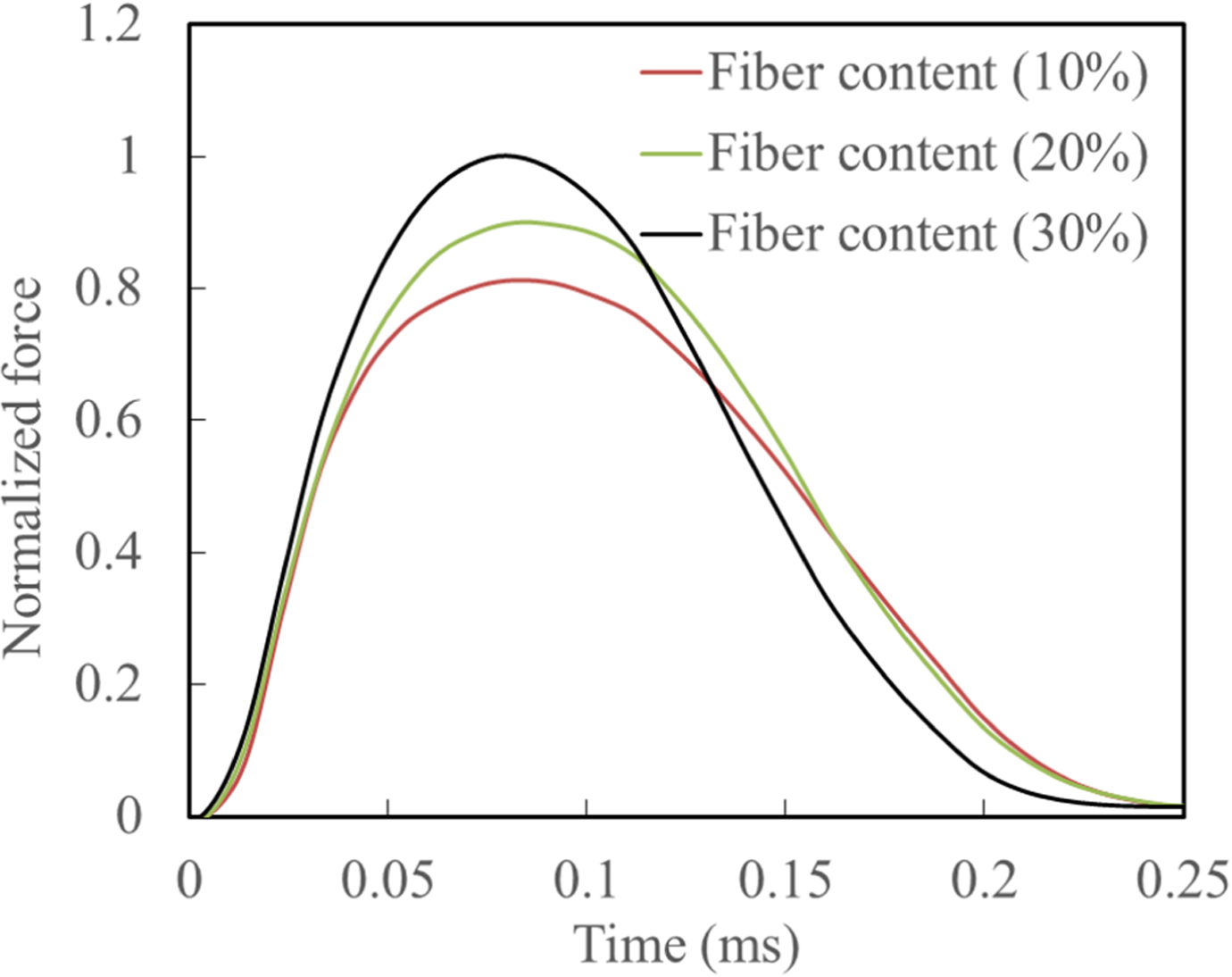
Evaluation for CMT specimens with different fiber contents. CMT: carbon fiber mat–reinforced thermoplastic.
Conclusions
In this study, a tapping system with controllable tapping velocity and force was designed to evaluate the defects inside CMT and CTT. The feasibility and sensitivity for using the amplitude and contact duration of the interactive force to identify voids and delamination of the composites were investigated experimentally.
Mathematical expressions (i.e. the contact duration and the amplitude of the interactive force) were derived to quantify the local stiffness of CFRTP. Contact duration was related to the mass of the tapping block but was found to be independent of the tapping velocity.
The force–time curve was often neither a strict sine curve nor a non-closed curve with the time axis in practical tapping tests. Therefore, the amplitude of the interactive force profile should be measured to evaluate the health condition of CFRTP instead of using the contact duration.
The tapping system could identify the delamination with a depth of less than 2.0 mm, the void-containing region with void content greater than 2.0%, and the resin-rich region where the fiber content of tapping area was 10% different from that of surrounding areas. The sensitivity and accuracy of this tapping system decreased significantly with decreasing dimensions and increasing defect depth under the specimen’s surface.
Footnotes
Authors’ Note
Part of this study belongs to the Japanese METI project “the Future Pioneering Projects/Innovative Structural Materials Project” since 2013.
Acknowledgements
The authors would like to express sincere appreciation to the other project members who have provided valuable information and useful materials. The authors also wish to express their appreciations to Dr Liaojun Yao (Harbin Institute of Technology) for his valuable contribution in discussion and suggestion on this work.
Declaration of Conflicting Interests
The author(s) declared no potential conflicts of interest with respect to the research, authorship, and/or publication of this article.
Funding
The author(s) received no financial support for the research, authorship, and/or publication of this article.