
Abstract
This article presents a transient thermal analysis of laser-assisted thermoplastic tape placement at high process speeds. The article revises modeling simplifications made in the literature and introduces novel ones. Analytical solutions to the thermal problem are proposed, for the heating and the cooling period. The process analysis of high speeds assumes a high-power laser in combination with a well-functioning temperature control. Due to this assumption, the final (surface) temperature is kept equal in all analyzed cases. The process analysis will show that the through-thickness temperature distribution changes significantly at higher speeds and becomes the determining factor for the bond interface temperature. General conclusions about process design and limits of tape placement are drawn. Finally, novel control methods are presented, which promote a dual control of surface temperature and temperature distribution. It will be shown how this is achieved by appropriate setting of the laser power and heating length.
Introduction
Laser-assisted tape placement enables the processing of unidirectional fiber-reinforced thermoplastic tapes at high speeds with precise (surface) temperature control. High-intensity and low response times are the main advantages of using lasers as heat source. The process and its systems gain interest in several industries, which want to utilize unidirectional fiber-reinforced thermoplastics as material for lightweight products. Especially high-volume production of durable components is of interest, such as pressure vessels, pipes, or semistructural automobile parts. Furthermore, a combination with injection molding offers the possibility to create hybrid thermoplastic parts of high geometrical complexity with additional functional integration.
In order to optimize the parameters of tape placement processes accurately, a thorough understanding of the thermal behavior is essential. It is also the basis for choosing optimal parameters for closed-loop controls. In the last decades, several thermal models of the process have been proposed and solved—either analytically or numerically.
Analytical solutions have been presented by Ghasemi Nejahd et al. for the case of a general heat source, 1,2 by Dai and Ye for the case of hot-air-assisted tape placement, 2 and by vor dem Esche and Schmidt for the case of laser-assisted tape placement. 3,4
Lee analyzed different heat sources for towpreg heating by use of analytical solutions. 5 For analyzing the cooling process and the respective crystallization, Lee used an analytical solution as well. 6 Other authors used these solutions for material-specific process analysis, like Steyer and Stimpfl. 7,8
Numerical solutions have been presented by James and Black as well as Toso and Ermanni for infrared-assisted tape placement, 9,10 by Kim for hot-gas-assisted tape placement, 11 by Latrille for flame-assisted tape placement, 12 and by Grove, Beyeler and Güçeri, Sonmez and Hahn, Agarwal et al., Koelzer, Grouve as well as Stokes-Griffin and Compston for laser-assisted tape placement. 13 –21
Using numerical solutions makes it possible to consider various heat flows, boundary conditions, and temperature-dependent material properties. This is challenging for analytical solutions, because the parabolic differential heat equations are difficult to solve. It can be safely assumed that numerical solutions lead therefore to results of higher accuracy, if the input data, like material properties, and the solving parameters, like the mesh size and step time, are chosen accurately.
Nonetheless, the advantage of analytical over numerical solutions is that they can deliver results with less computation time. Several processes can be analyzed simultaneously with very high resolution in the time domain and along the geometry of interest. Process design can be accelerated and process knowledge can be generated quickly. Whenever the results of an analytical solution correspond with the results of a validated numerical solution, to a degree, which is good enough for practical purposes, they are mostly preferred.
This article will present the use of analytical solutions for the transient thermal problem of laser-assisted tape placement. Especially, heat accumulation in bodies of finite thickness, for example thin tapes or thin substrates, and cooling after heating will be considered. A strong focus is placed on the through-thickness temperature distribution and its influence on the bond interface temperature. Prerequisite for valid analytical solutions is a feasible simplification of the problem, in order to be able to solve the parabolic differential equations with the mathematical tools available. Limits and constraints of the model have to be well defined, in order to avoid false usage.
Material properties
Table 1 presents the (averaged) material properties considered in this article. One material is used for the analysis: carbon-fiber-reinforced thermoplastic (C-FRP) with polyetheretherketone (PEEK) as matrix material. The values are taken from Cogswell. 22 Furthermore, this article will investigate the significance of temperature-dependent material properties. These values are taken from Koelzer. 18
Averaged material properties.
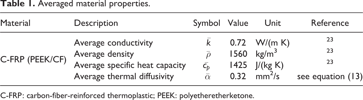
C-FRP: carbon-fiber-reinforced thermoplastic; PEEK: polyetheretherketone.
Description of the problem
Figure 1 shows a principle system setup of a laser-assisted tape placement process—in this case a winding process. Most process strategies promote the heating of both tape and substrate. Grouve, on the other hand, proposed the exclusive heating of the tape as an alternative, because the tape is able to store the heat better than the (mostly) thicker substrates, which transfers the heat more rapidly into its core.23 Grouve used the results of numerical simulations to get to this conclusion.
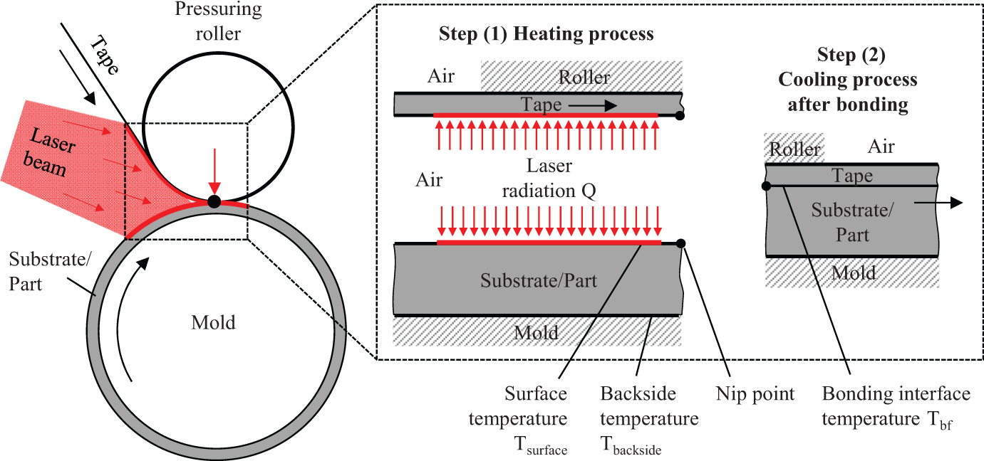
Focus of the transient analysis: heating and subsequent cooling shortly thereafter, in laser-assisted tape placement (schematically drawn, not to scale).
In general, several modes of heat transfer occur, which lead to the complexity of the problem: conductive heat transfer in width direction—thermal aspect 1; conductive heat transfer in fiber direction—thermal aspect 2; conductive heat transfer in thickness direction—thermal aspect 3; radiation and convection at the surface to the environment (front side and backside)—thermal aspect 4—, with the convection being a function of speed—thermal aspect 5; heat transfer from the backside of the tape to the pressuring roller—thermal aspect 6; heat transfer from the backside of the substrate to the mold (represented as a mandrel in Figure 1)—thermal aspect 7.
When the tape and substrate get into contact, a heat transfer resistance shortly occurs. This thermal resistance quickly decreases with increasing degree of intimate surface contact—thermal aspect 8. The materials are anisotropic regarding their thermal conductivity: The tape is more conductive in the fiber direction—roughly 8–10 times, in the case of a carbon fiber tape. The conductivity of the substrates can vary in many directions, depending on the layup of the part—thermal aspect 9.
Furthermore, heat capacity and conductivity are temperature dependent 3,13 —thermal aspect 10. Most heated bodies in tape placement are finite in their thermal character, which means when heat reaches the backside, heat can accumulate 23 —thermal aspect 11. Strictly described, the tape is bent and the substrate is curved. This can also influence the heat transfer in principle as well—thermal aspect 12. Ideally, the heating/melting of the material(s) is accomplished as close as possible next to the nip point, to limit the cooling before bonding.
Due to optical phenomena, this is mostly not possible: Shading, reflectance, and reduced intensity by the geometry of the roller and part can play a role. 13,18,19,24,25 The heat flux distribution is therefore nonhomogeneous along the heating length—thermal aspect 13; the shading effect creates an area before the nip point where no heat flux is present—thermal aspect 14. The irradiation time can change, depending on the process speed or situation, for example, at start and stops, or when the manipulator slows down while moving around sharp edges—thermal aspect 15. The laser beam is in principle able to penetrate the material, leading to volumetric absorption, rather than surface absorption 3 —thermal aspect 16.
The latent heat of fusion and the crystallization process can act as a heat source or heat sink in the process 15 —thermal aspect 17. Further, a low degree of intimate contact between tapes within the laminate can act as interlayer contact resistances. These do influence the heat transfer within the substrate, leading to higher thermal gradients—thermal aspect 18. 16 Finally, as the induced heat is stored in the substrate for some time, subsequent processes differ thermally, because the substrate is already preheated—thermal aspect 19. Consideration of the thermal aspects yields to the subsequent general differential equation:

with ρ being the material density, cP being the temperature-dependent specific heat capacity, vP being the process speed, kx, kzy being the temperature-dependent thermal conductivities in fiber and thickness/width direction. The right term of the equation represents the heat source r caused by crystallization (for detailed explanation, the author refers to the study by Sonmez and Hahn 15 and Stokes-Griffin and Compston 19 ). The latent heat of fusion can be modeled by the temperature-dependent specific heat capacity cP. The following initial condition applies: Ti = T0.
Finally, the following boundary conditions have to be considered for the (front side) surface:

(the effect of laser penetration is not considered), and the following boundary conditions for the backside:
Subsequently, the surface temperature is synonymous with the temperature at the front side. The coefficient hrad depends on the temperature and hconv depends on the speed at which the material moves through the atmosphere. An analytical solution to this parabolic differential equation with all considered thermal aspects is difficult to obtain. No such attempt will be made in this article.
Derivation of the assumptions made: Model simplifications
Many complex physical processes can be approximated by the reduction to its most significant phenomena—and then solved analytically. Careful analysis of the process and clear definition of constraints is an essential prerequisite for a feasible simplification. Prior simplifications in the literature of thermoplastic tape placement will be revised and novel ones will be introduced.
First, some definitions have to be made: Figure 2 shows a general description of the thermal process. The figure divides the process into three dimensions for consideration: feed, width, and thickness. A coordinate system is introduced and will be referred to later.
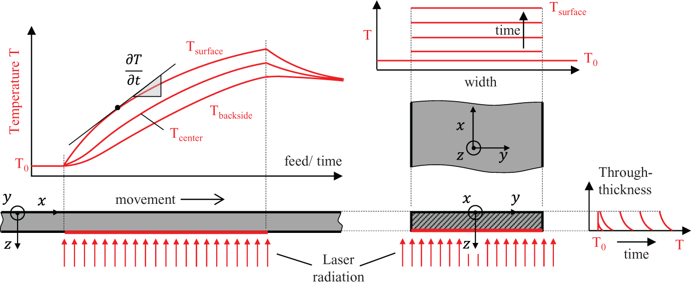
Dimensions for consideration: feed (x), width (y), and thickness (z). Exemplary for the case of the tape heating (schematically drawn, not to scale).
Heat transfer into the body
Vor dem Esche noted that the thermal resistance RL for the laser beam to turn into heat is quasi-infinitely low. Therefore, regarding heat transfer analysis, a thermal resistance does not have to be considered. 1 For deeper analysis on the laser-surface interaction, the author refers to the study by Poprawe. 25 This factor is one of the major advantages of photonic-assisted tape placement, compared to other technologies such as hot air, hot gas, flame, conductive heating, or any other mechanism, where a heat transfer coefficient is present. Due to the low thermal resistance, the Biot number for the heat transfer into the body Biin is quasi-infinitely high in laser-assisted tape placement:

Biot numbers larger than 0.2 will inevitably lead to thermal gradients, because the heat flow into the body at the surface is significantly larger than the conductive heat flow within the body. 26 This is a basic precondition in laser-assisted tape placement and will be important in later considerations.
Thermal aspects 1, 2, and 7
As the laser spot of most systems is larger than the bonding zone (overlapping left and right by >5 mm), and the thermal penetration depth δtherm is comparably low (<1 mm), this mode of heat transfer can be neglected, compare also Figure 2. Grouve already pointed that out in the literature. 23 This is obvious considering the large ratios between the width of the bonding zone and the tape thickness, ranging from 20 to 1000. Heat losses at the tape edges were proven negligible by Grove. 13
Although the thermal diffusivity α is roughly 8–10 times higher in the fiber direction than in thickness direction, this direction of heat transfer can be neglected. A single element of the tape is not affected by the anisotropy, because the element is moving through a relatively long heating zone (>20 mm) at high speeds (>50 mm/s). This has already been proven by Grove and was revisited by others. 13,23,24
Thermal aspects 4, 5, 6, and 7
Two values have to be introduced: first, the temperature difference between the tape and the environment ΔTtape−0. It is obtained by subtracting the internal temperature (at the surface) with the environmental temperature (usually ≈20°C; see Figure 3):
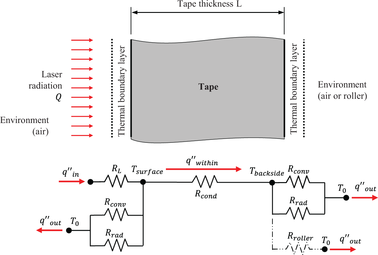
Thermal resistance model of laser-assisted thermoplastic tape placement; here exemplary for the case of the tape.

This value points to a potential for heat flow out of the body, due to Newton’s Law of Cooling (see equation (7)). The second value ΔTs−b is the temperature difference within the body, between the heated front side and the (mostly colder) backside. It is obtained by subtracting the surface temperature with the backside temperature and points to a potential for heat flow within the body.

The temperature difference to the environment ΔTtape−0 increases when the tape heats up; the temperature difference within the tape ΔTs−b only increases when thermal gradients occur, meaning when the surface temperature increases more rapidly than the temperature of the backside. This is commonly the case in laser-assisted tape placement.
With these two values, the thermal resistances of the process (see Figure 3) and the consideration of Newton’s Law of Cooling,
general statements about the cooling behavior in laser-assisted thermoplastic tape placement can be made. Two main thermal resistances have to be considered first: the thermal resistances within the body Rwithin and the thermal resistances out of the body Rout. The thermal resistances within the body consists of the thermal resistance by conduction Rcond, while the thermal resistances out of the body consist of either the thermal resistance by convection Rconv and radiation Rrad or by a thermal resistance to a solid Rsolid—to the roller, in case of the tape, or to a mold, in case of the substrate.
A general statement can be made about the relation between heat flow within and out of the body: If the temperature difference between surface and backside is smaller than the temperature difference between surface and environment, multiplied by their fraction of thermal resistance, heat flow out of the body is greater than the heat flow within the body and vice versa:

It can be investigated when this condition occurs in laser-assisted thermoplastic tape placement: First, the average thermal resistances of conduction, convection, radiation, and to a solid (roller/mold) need to be obtained by

The parameter L is the characteristic length—in our case, the distance from the heated surface to the less heated backside of the tape (exemplary for 0.2 mm).
Average heat transfer coefficients in thermoplastic tape placement.
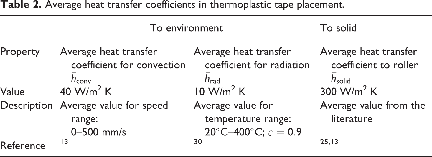
The results are Rcond = 278 K/W, Rconv = 25,000 K/W, Rrad = 100,000 K/W, and Rsolid = 3333 K/W. For the case of radiation and convection, we need to set the thermal resistances in parallel:
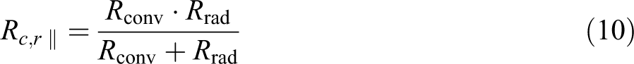
The result for Rc,r ∥ is 20,000 K/W. This value represents the thermal resistance for the tape to cool down by convection and radiation at the backside and the surface (front side) during heating and to the backside after the bonding process. It can be observed that the thermal resistance to a solid (roller/mold) is significantly lower than the thermal resistance by convection and radiation (six times; see Figure 4). Nevertheless, the thermal resistance within the body by conduction is by far the lowest thermal resistance: roughly 70 times lower than the resistance for convection/radiation and roughly 12 times lower than to a solid (roller or mold). As Newton’s Law of Cooling states, whenever thermal differences occur, heat will flow the easiest way possible.
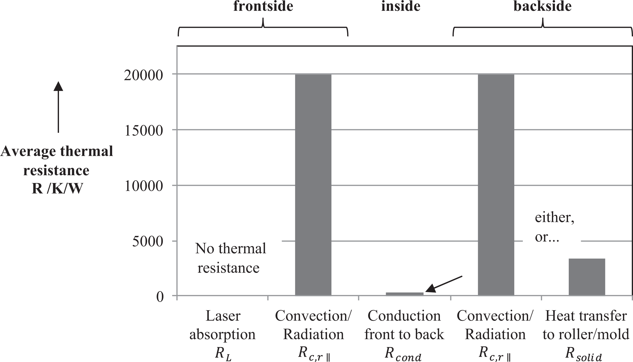
Average thermal resistances in laser-assisted thermoplastic tape placement for the case of a PEEK/CF tape of 0.2-mm thickness. PEEK: polyetheretherketon; CF: carbon-fiber.
Therefore, it can be concluded, that in thermoplastic tape placement, The heat will rather distribute internally by conduction (even if only small thermal gradients exist) rather than to leave the tape out to the environment (air/roller). The temperature difference within the body ΔTs−b has to be 70 times lower than the temperature difference between surface and environment ΔTtape−0 in order for the heat to leave the body more easily than to flow within the body.
With the derived values, it is possible to calculate the dimensionless Biot number again; this time in order to characterize the thermal behavior during the cooling process:

The result is a Biot number Biout of ≈0.08, for the case of the contact to a solid (roller/mold), and ≈0.014 for the case of parallel convection and radiation. For Bi numbers <0.2, thermal gradients tend to decrease by internal conductive cooling rather than to increase by surface cooling. 26 Again, this analysis proves that the heat will rather distribute within the tape, than to leave the tape at the backside or the surface. It can be summarized that the dominating effect for cooling of the bond interface, shortly after contact, is internal conduction. The system is quasi-insulated toward the environment unless the thermal gradients approach equilibrium. Only for equilibrium state, cooling by convection/radiation and to the surrounding solids (roller/mold) begin to play a significant role.
Thermal aspect 8
When tape and substrate contact each together, a heat transfer resistance occurs and quickly decreases with increasing degree of intimate contact. The general heating strategy in thermoplastic tape placement is an equal (surface temperature) heating of tape and substrate. 18 The cooling behavior of the bond interface is therefore only slightly influenced by asymmetrical cooling of tape and substrate, shortly after bonding. Therefore, this thermal aspect is neglected in the analysis of later sections.
Thermal aspect 10
As the literature suggests, the temperature-dependent properties of most materials used in thermoplastic tape placement can be averaged over their heating range (between Ti and Tmax). This simplification has already been used by many authors. 1,3,7,8,28
Thermal aspect 12
Because the thermal penetration depth in thickness direction δtherm ⊥ is low (<1 mm) compared to the roller radius (≈40 mm) and compared to the curvature of most parts (e.g. in pipes of >50 mm radius), the heated bodies can be simplified as slabs in most cases. This is obvious and has been assumed by most authors. For a deeper analysis on heat transfer in curved geometries, the author refers to the literature. 26,29
Thermal aspects 13 and 14
The irradiance distribution in the process zone is generally not homogeneous, because the roller and part geometry, as well as reflection, significantly influence how the laser radiation is transformed into actual heat flux into the material. 18,19,24,25 However, equations for the thermal penetration depth δtherm suggest that the thermal penetration depends only on the irradiation time, rather than the magnitude or distribution of the heat flux. 26

Furthermore, different machine setups (mold geometry, roller diameter, laser system angle) can lead to different irradiance distributions. For the transient thermal analysis presented in this article, a constant averaged heat flux over time and space is therefore assumed. The shading area can also vary significantly, depending on the machine setup. Because this study has the purpose of making general statements about the through-thickness temperature distribution at high speeds, it will therefore be neglected.
Thermal aspect 15
The irradiation time can change, depending on the process situation, for example at starts or at stops. But, as most manufacturing processes are carried out at constant speeds, we assume the irradiation time to be constant. This assumption has been made by most authors.
Thermal aspect 16
In C-FRPs, the most upper layers of carbon fibers act as a strong absorber, leading to a surface heat flux. 7,8,19,23 Glass-fiber-reinforced thermoplastics are mostly blackened by fillers today, leading to surface absorption as well. 7,28 Therefore, the laser penetration depth δL is in most cases of the industrial applications much smaller than the heat penetration depth (δL ≪ δtherm). In consequence, we can assume a surface absorption in our thermal analysis. 25
Thermal aspect 17
The latent heat of fusion of the polymer and the crystallization can influence the heat transfer by acting as a heat sink in the heating phase and as a heat source in the cooling phase. Nonetheless, compared to the other modes of heat transfer, it is a weak thermal phenomenon and has therefore been neglected by many authors. 1,30,31
Thermal aspect 18
This article assumes the substrate to be well consolidated with maximum degree of intimate contact between the tapes. Additional interlayer contact resistance is therefore neglected.
Thermal aspect 19
Finally, because the focus of this study is the “cold” in situ process with a non-preheated substrate, this thermal aspect is neglected as well.
Transient thermal model and analytical solutions
As derived in the previous section, for many cases, the thermal problem of laser-assisted tape placement can be simplified as two slabs, which undergo a certain surface boundary condition. This kind of model has been used by Dai and Ye, 30 vor dem Esche, 3 Lee, 5 and Tierney and Gillespie. 28 Nonetheless, the most significant unconsidered effect in the analytical solutions so far has been the case of heat reaching the back of the slabs—tape or substrate—so that heat accumulation occurs (subsequently named as finite slabs). Slabs of infinite thickness can only be assumed when this effect is ruled out (these bodies are subsequently named as semi-infinite slabs). This distinction has solely been considered by Dai and Ye 30 for the case of hot-air-assisted tape placement with a Dirichlet boundary condition—constant surface temperature. Because heat accumulation is also one of the key phenomena of laser-assisted thermoplastic tape placement, this effect deserves further analysis and investigation, especially at higher tape placement speeds. For laser-assisted tape placement, a Neumann boundary condition has to be applied—constant surface heat flux.
According to the model simplifications made in the previous section, the thermal problem described in equation (13) can be approximated by the subsequent parabolic differential equation and initial condition (body temperatures are equal to environmental temperature):
and the following boundary conditions for the surface (heat flux) and the backside (insulation):
with

with a being the absorptance on the material. In this article, we will assume the absorptance to be 1, which leads to
Transient heat flow in tapes and substrates of finite thickness with surface heat flux
For bodies of semi-infinite thickness, where heat does not reach the back, solutions are well known and presented by Poprawe, Bejan, and Bergman and Lavine. 25,28,31 Those solutions have been used for analysis of laser-assisted tape placement by vor dem Esche, Stimpfl, and Steyer. 3,7,8 However, they are not applicable to the described common occurrence of heat accumulation, especially in thin tapes, thin substrates (and slow processes). Recent mathematical solutions to the thermal problem of heat accumulation were identified in the study of Faghri et al. 27 The nonhomogeneous problem described by equation (13) does not have a steady-state solution. Therefore, a partial solution is not applicable. The method of variation of parameters was used by Faghri to solve the problem. 27
The mathematics of the derivation is long and tedious and not the focus of this article. The equation describes the temperature within a body, as a function of time and location in the through-thickness direction z (compare Figure 2). The equation is valid under the following boundary conditions:

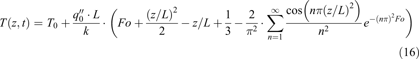
other than the conventional mathematical solutions, which are only valid for 0 < Fo < 0.2. Equation (16) can be utilized for finite as well as semi-infinite bodies/processes. The final time after heating is defined as tp. Figure 5 shows the resulting thermal penetration of a conventional tape placement process. In this parameter setting, the heat significantly accumulates within the tape, because the heat cannot flow out of the tape at the backside, as it can within the substrate (compare Figure 4). By using equation (16), one can further derive mathematical descriptions of the
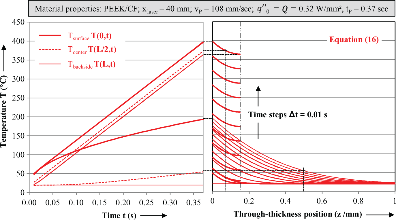
Result of the analytical solutions for two laser-assisted thermoplastic tape placement processes undergoing the same heat flux: Lfinite = 0.15 mm for a tape and L∞ = 1 mm, for a substrate.
surface temperature Tsurface by setting z to 0,
backside temperature Tbackside by setting z to L, and
temperature in the center of the body by setting z to L/2 (see Figure 5, left diagram).
With the derived equations, it is possible to plot the solution in the time domain (∼feed) and in the through-thickness direction z for two thermally different bodies: finite thickness (Lfinite) and semi-infinite thickness (L∞). The process parameters were chosen on purpose to show the fundamental difference in the heating behavior.
The results reveal a significant difference in the heating characteristic between semi-infinite and finite bodies in tape placement. By plotting solely the surface temperature for three bodies of different thicknesses, which could be tapes or thin substrates, we can identify the time (or speed) at which the surface temperature significantly deviates, only due to its thickness (Figure 6). The heating length is kept constant, as it is not adjustable in most tape placement systems 35–38.
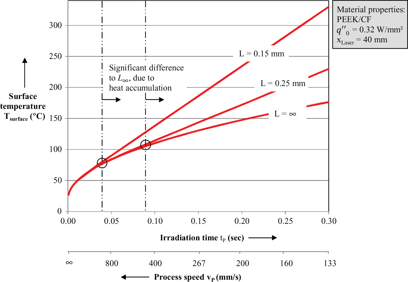
Analysis of surface temperatures for fiber-reinforced thermoplastic bodies of different thicknesses.
Generalization of heat accumulation in thermoplastic tape placement
That heat accumulation generally occurs in laser-assisted tape placement has already been recognized by Grouve
22
and others by numerical simulations. The general parameter setting for when heat accumulation occurs in thermoplastic composite bodies is unknown so far. It can be derived by considering the Fourier number Fo. The

The lower Fo, the more a body/process tends toward thermal gradients and therefore less toward whole-body heat accumulation; the higher the Fo, the less a body tends to thermal gradients and therefore more toward whole-body heat accumulation, because the heat reaches the back of the body faster. The higher the exposure time t and conductivity k of the material, the higher is the Fo; the higher the heat capacity cP and density ρ of the material, the higher is the characteristic length of the body L, for example tape thickness, the lower Fo.
The Fourier number at which finite bodies and semi-infinite bodies differ from each other can be approximated to Fo ≈0.2.
29
Therefore, only one ratio between irradiation time and body thickness exists (for a given material), when heat reaches the back. The thermal penetration depth δtherm is mostly driven by the irradiation time (see equation (12)). By substituting equation (12) into the correlation
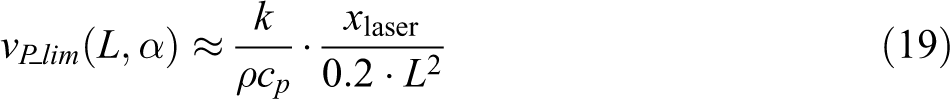
With this equation, it can determined if tape or thin substrate accumulates heat in the process or not.
Transient heat flow after cooling in tapes and substrates of semi-infinite thickness
In previous sections, it was shown that the dominant mode of heat transfer for cooling is internal conduction (see Figure 4). Utilizing this simplification, solutions to equation (13) for the temperature distribution after cooling can be obtained
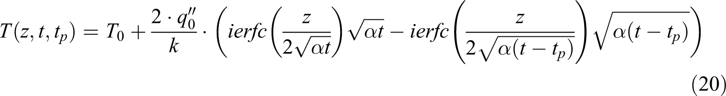
with tp being the time after heating and t being the overall considered time. 25 Because this solution does not consider the heat accumulation effect, prior to cooling, it is only valid under the following conditions:

The cooling time tc is obtained by the considered time t subtracted by the heating time tP:

Equation (20) can be used to analyze the (general) cooling behavior after heating and after bonding, without consideration of heat flow between tape and substrate (see the analysis in Figures 7 and 8). We can obtain an equation for the surface temperature after cooling by setting z to 0. Equation (20) is not valid for finite slabs, when heat reaches the backside of the body and accumulates (significantly; see Figure 5). At the moment, no mathematical solution for this problem has been realized. Moreover, when the tape gets into contact with the temperature profile of the substrate, the heat exchange has to be considered. For the moment, this requires numerical simulations.
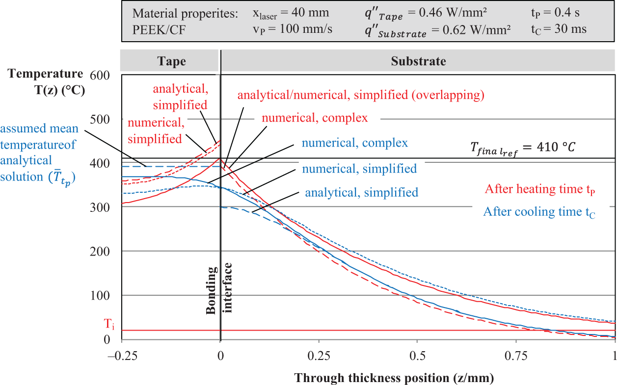
Comparison between numerical solutions of the complex model, numerical solutions of the simplified model, and analytical solutions of the simplified model. Heat exchange is only modeled in the numerical solutions.
Temperature distributions after heating and shortly after cooling in laser-heated bodies of C-FRP, for different process speeds, but for the same final surface temperature after heating. The temperature distribution after cooling within the tape is set to equilibrium. Heat exchange after bonding is not modeled. C-FRP: carbon-fiber-reinforced thermoplastic.
Accuracy validation of the model and analytical solutions
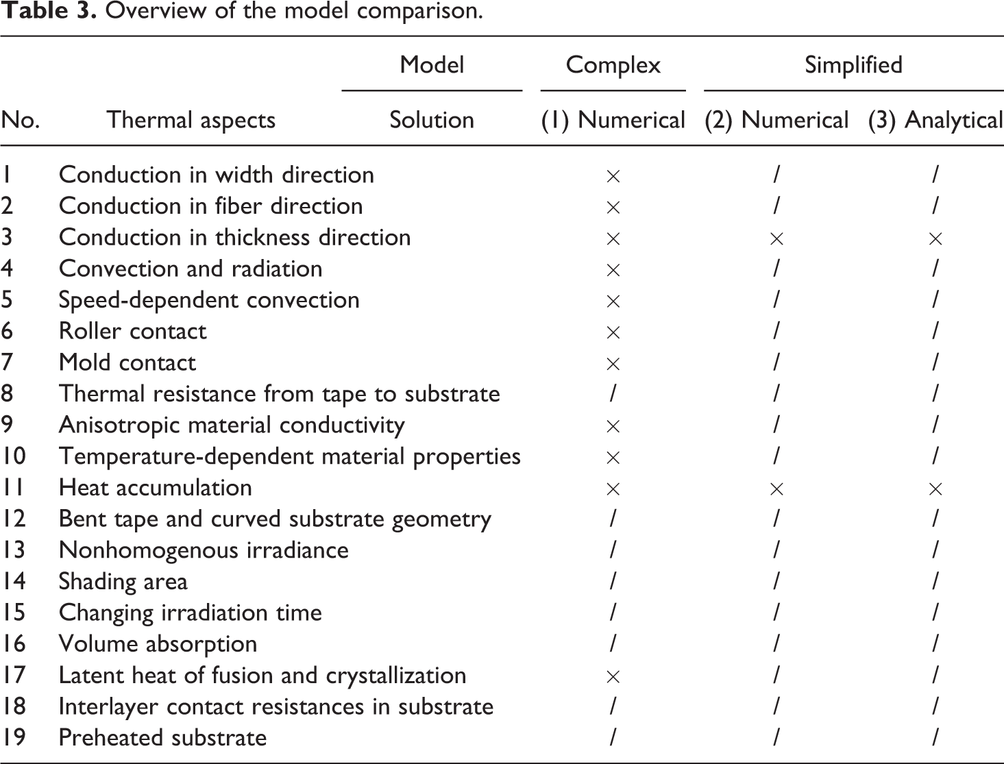
Before using the simplified model and its analytical solutions for process analysis, a validation was done, in order to assess the accuracy. Eight numerical simulations have been carried out to create a comparative measure: four for heating and four for cooling (see Table 4 and Figure 7). The analytical solutions include the same thermal aspects as the simplified numerical solution: constant heat flux
Overview of the model comparison.
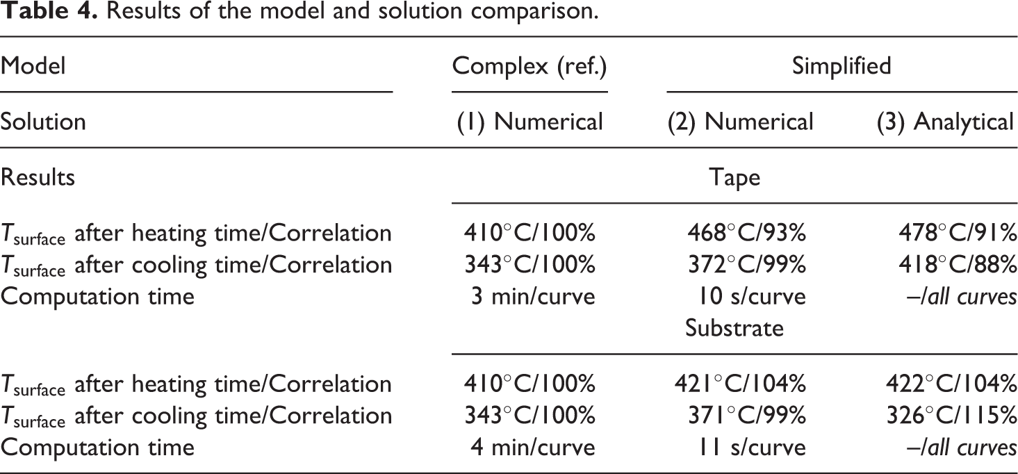
Results of the model and solution comparison.
Heat exchange between tape and substrate is only modeled in the numerical solutions. The temperature profile in the tape after cooling is assumed as equilibrium for the analytical solution, as no analytical solution for this thermal problem exists. The final temperature profile after heating was therefore averaged. Some of the more obviously negligible thermal aspects are also neglected in the complex model for practical purposes (see Table 3). The study focuses mainly on the impact of high speeds on the thermal gradient.
The temperature-dependent material properties were taken from Koelzer. 18 The material properties were averaged for the temperature range of 20°C–425°C for the simplified model. This is roughly in the range from Ti to the final surface temperature of tape and substrate. The roller contact is assumed to be along the whole heating length.
Figure 7 shows the different temperature distributions with a promising correlation among the three cases. A quantitative correlation among the solutions was obtained by

with Tsurface,cM being the final surface temperature of the complex model (numerical) and Tsurface,sM being the final surface temperature of the simplified model (numerical or analytical).
Table 4 summarizes the results. It can be observed that the solution of the complex model possesses higher temperatures in the case of the semi-infinite body, but slightly lower temperatures in the case of the finite body. This can be ascribed to the averaging range of the temperature-dependent material properties (heat capacity and conductivity). Further, the additional difference at the backside of the tape can be ascribed to the roller contact, because this is the only thermal aspect, which exclusively affects the tape. The simplified model represents a good approximation of the complex model, even after the cooling period (blue-dotted curves).
The only exception is the cooling profile of the analytical solution, which deviates <15% at the surface temperature after the considered cooling time. This can be ascribed to the nonmodeled heat exchange between tape and substrate. The heated tape keeps the substrate surface at higher temperatures, in the numerical solutions. The longer the considered cooling time, the more the analytical solution will deviate from the numerical solution. Nonetheless, as we only want to analyze the temperature profiles shortly after the nip point until Tsurface becomes < Tmelt, this deviation is rather negligible.
In view of practical tolerances of the material property data, the simplified model and its analytical solutions seem to be a feasible easy tool for analysis of laser-assisted thermoplastic tape placement. The general temperature distributions within the substrate and within the tape are almost proportional along the through-thickness position z, in all cases, compared to the complex model. The most significant mode of heat transfer (through-thickness heat conduction) and the most significant boundary conditions (heat flux and irradiation time) are represented.
Analysis of thermal gradients at high speeds
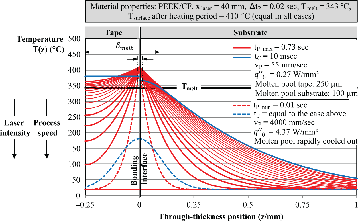
Laser systems on the market today can provide powers of >10 kW, for example, for laser cutting; optics for their precise focusing are available. 32 In addition, closed-loop controls with contact-free temperature measurement are able to control a desired surface temperature accurately within a narrow process window. 33 Considering these technological boundary conditions, the question arises if laser-assisted tape placement is limited (thermally) at higher speeds at all. To answer this question, theoretical investigations were done with the model, as presented in this article. The general thermal behavior at high speeds and high laser intensities in the through-thickness direction z is the focus.
To describe the thermal behavior in more general terms, temperature distributions at high speeds were calculated for the same final surface temperature. This is essentially the boundary condition, which a high-power laser in combination with a well-functioning closed-loop control system would enable. To show what would happen in this configuration, equation (16) is converted to the heat flux
By substituting the heat fluxes from equation (24) into equation (16), the temperature distributions for different speeds and laser intensities can be calculated. The final surface temperature is set to 410°C, to meet the required melting temperature of PEEK. Figure 8 shows the result of two conventional bodies: a tape of 0.25 mm and substrate of 1 mm. The temperature distribution after a certain cooling time tC is calculated for the highest and the lowest thermal gradient with an equal cooling time of 10 ms.
The investigations reveal the following general phenomenon: The thermal penetration depth δtherm decreases significantly with higher speeds (see equation (12)). For low-speed processes, it can be observed that much more heat has accumulated within the material. For high-speed processes (with high laser intensity), the surface temperature drops much more rapidly in the cooling period. This can be explained by the higher potential for heat flow, due to a lower thermal resistance for conduction (see Equations (7) and (9)). Glass-fiber tapes possess lower thermal diffusivity than the considered examples with CFRP. Glass-fiber-reinforced thermoplastics tapes will therefore tend to stronger gradients than C-FRP tapes.
It is also possible to obtain the depth of molten polymer δmelt, by asking when equation (16) is equal to the melting temperature of the polymer Tmelt (see Figure 8). The equation cannot be solved for the through-thickness position z analytically. Therefore, the position in z was identified graphically as shown in Figure 8. The same can be done for time periods after cooling, by asking when equation (20) equals the melting temperature Tmelt. Figure 9 shows the result of all graphically identified depths of molten polymer δmelt after heating and after one exemplary cooling period of 2.5 ms.
For low-speed processes (with low laser intensity), it can be observed that significantly more of the polymer is molten; for high-speed processes (with high laser intensity), the molten pool cools out increasingly rapid. The decrease rate of the molten pool Δδmelt increases with higher thermal gradients. Figure 9 reveals that it becomes increasingly more difficult to remain a molten pool at very high speeds and very high laser intensities. The strong thermal gradients transfer the heat into the core of body more quickly. Even if the polymer stays molten during the shading area, because of the higher speed by which it moves through it, the bond interface will cool out increasingly rapid during and after the nip point.
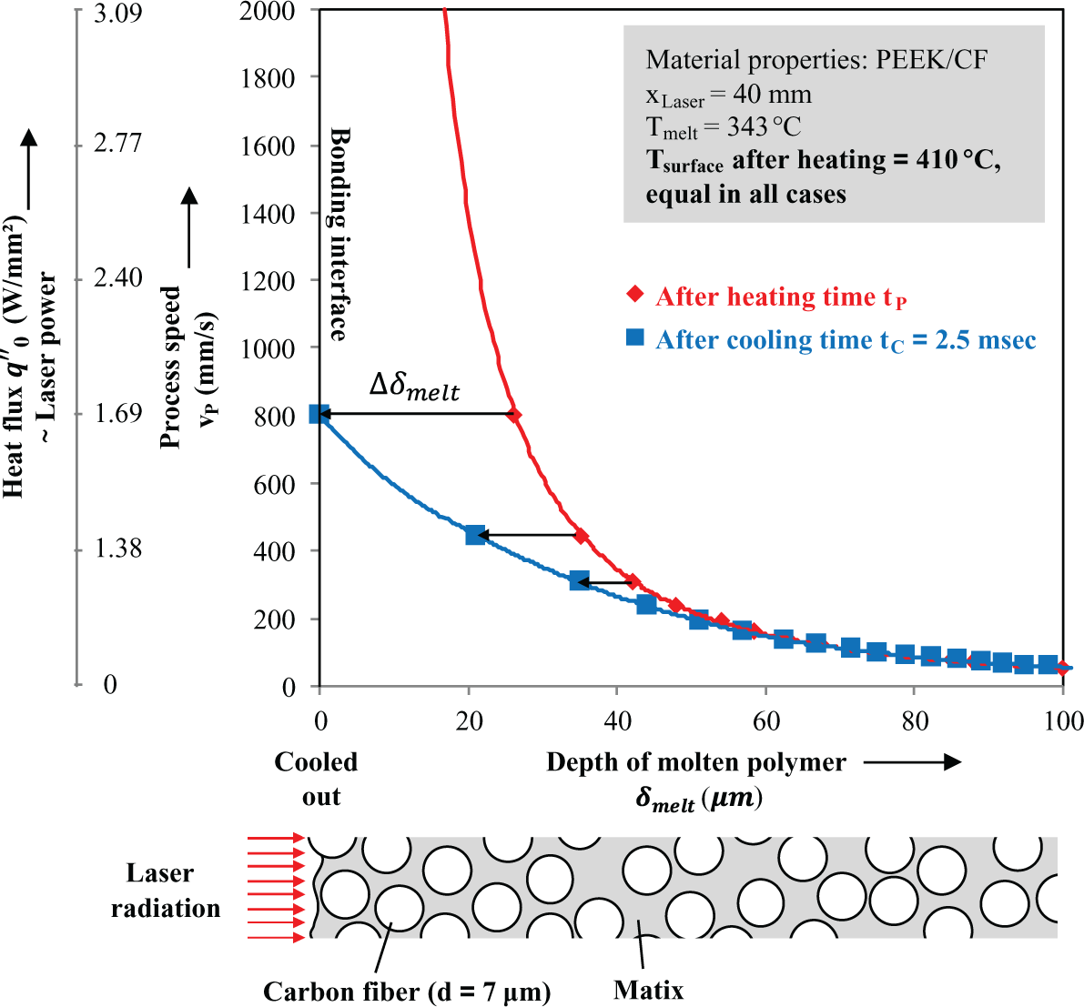
Depth of molten polymer after heating and shortly after cooling for a semi-infinite PEEK/CF body. The final surface temperature after heating is in all cases 410°C, by appropriate setting of irradiation time and heat flux (∼laser power). The corresponding thermal gradients can be taken from Figure 8. PEEK: polyetheretherketon; CF: carbon-fiber.
The positive effect of higher thermal penetration is more significant for the case of finite bodies, where heat accumulation occurs and the heat cannot flow to a core by conduction, see Figure 8, left side (tape). The heat storage process is a beneficial (and maybe essential) effect for in situ tape placement.
Considering Figure 8, it can also be observed that the heat penetrates previous bonded interfaces at higher temperatures, in the case of lower speeds and lower laser intensities (additional thermal barriers neglected). The high thermal penetration could therefore lead to better post-consolidation of previous layers—especially when tapes are thin, for example, 0.1 mm. This could explain another cause of the “last layer principle,” which states that the inner layers of a part, for example, a pipe, usually possess higher interlaminar shear strength than the outer layers. The effect is well known and described in the study by Stimpfl. 7 The schematic cross-section in Figure 9 also shows that the temperature distributions of Figure 8 can only describe an approximation of the real temperature distribution at the surface, which depends on the micro heat flows at smaller scales of the fibers and polymer. Very high thermal gradients may lead to unmolten polymer clusters, because only the fibers absorb the laser if the polymer is not blackened by fillers. This is the case in most C-FRP tapes.
Process control of thermal gradients
In view of the conclusions from the last section, it seems beneficial to seek solutions to the issue of rapid cooling by strong thermal gradients. In order to find the right control values for such an approach, we first use equations (16) and (24) to derive a correlation between surface temperature Tsurface, irradiation time t, and heat flux
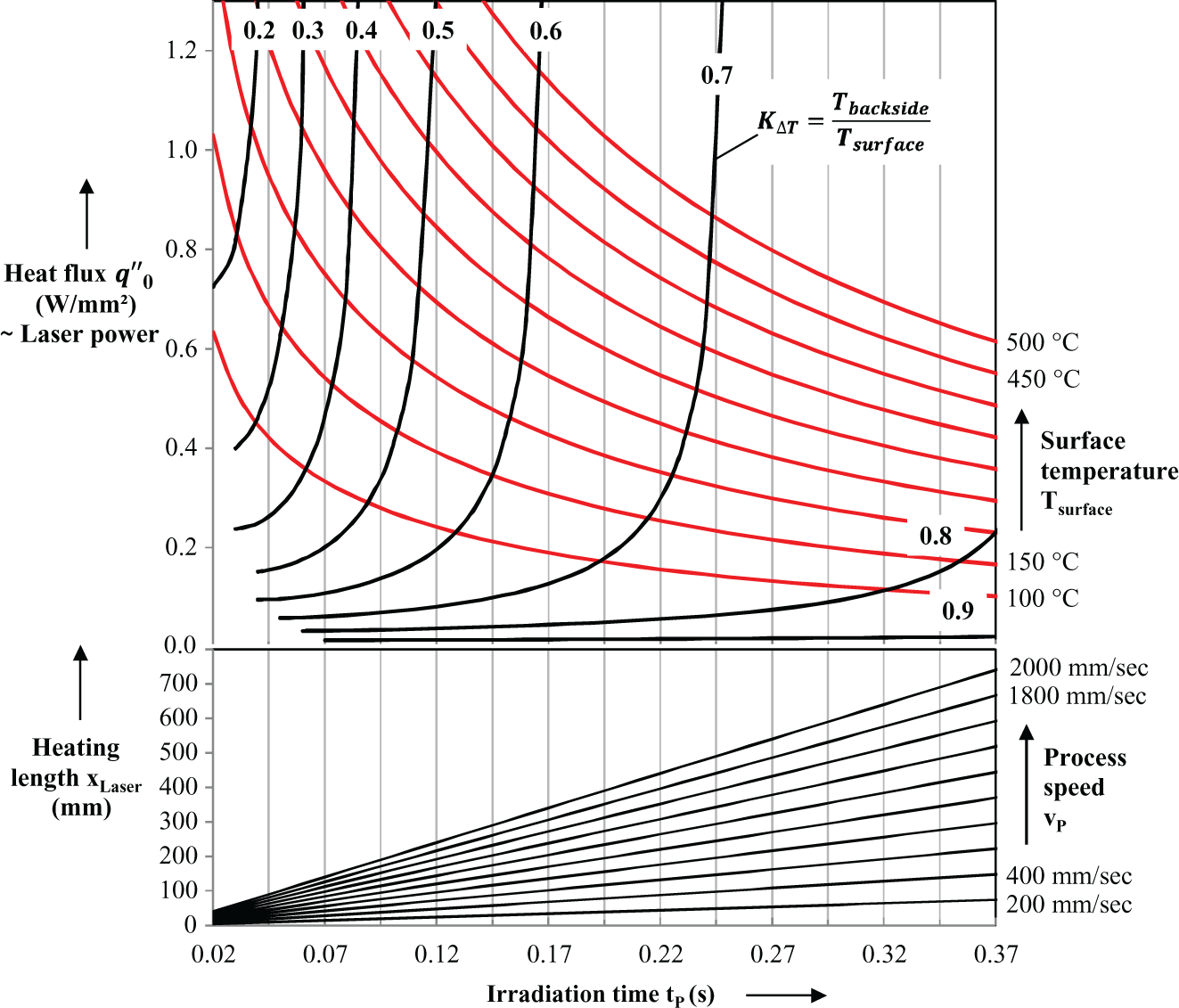
Diagram for simultaneous control of surface temperature (red curves) and temperature ratios (black curves) for thermoplastic tape placement of 0.25-mm-thick tapes with PEEK/CF properties. PEEK: polyetheretherketon; CF: carbon-fiber.
Information about the temperature distribution is still missing. To obtain a measurable value of the temperature distribution, we will therefore define the ratio between backside and surface temperature, KΔT. To obtain it, we divide T(L,t) by T(0,t) in equation (16):

It is a dimensionless number between 0 and 1, with 1 being the equivalent to equilibrium and 0 being an infinitely high gradient. By converting the equation to, we derive the following equation for the heat flux as a function of KΔT:
Using this information, it is possible to plot all correlations in one diagram and obtain an overview about which irradiation time and which laser intensity has to be set in order to reach a certain surface temperature Tsurface and a certain temperature ratio KΔT (see Figure 10, upper diagram with black curves). Finally, by adding the correlation between the heating length xlaser (additional manipulated variable), processing speed vP and irradiation time tP, we obtain a picture of how to control surface temperate and temperature ratio simultaneously (see Figure 10, lower diagram).
A correlation with the temperature ratio KΔT is only possible for finite bodies. For controlling the thermal penetration depth within thicker bodies or for in situ processes of very high speeds, where the heat does not reach the back (Fo < 0.2), another characteristic value of the temperature distribution has to be defined. The author proposes the temperature ratio between the surface temperature and the temperature at a depth of 100 µm (T100 µm / Tsurface). This temperature ratio is obtained by T100 µm / Tz=0.
Following the logic of the control diagram in Figure 10, it may be possible to further improve the maximum tape placement speeds beyond the limits of today, by increasing the heating length purposefully, rather than the laser power. The in situ process seems to be scalable in terms of controlled thermal condition. Increasing the heating length is an approach, which goes in the opposite direction of most previous system developments. Practical purposes may be the reason for that, like short heating lengths lead to easier guidance of cold (solid) tapes, closely before the bonding zone short heating lengths lead to short starting lengths, which lead to less scrap, especially in the manufacturing of small-sized tailored blanks
34
Nonetheless, winding processes, especially continuous winding processes, do not have these requirements. Machine dynamics at high speeds are also less of a problem. Therefore, winding processes could be a good test case for the hypothesis of process scalability. Lastly, higher speeds also lead to shorter consolidation pressure. This reduces the time for the development of intimate surface contact. Sequencing more pressuring rollers or using other pressuring mechanisms, like the tape tension, could solve this issue.
Automated control of the thermal gradient
Conventional closed-loop controls utilize the surface temperature as the process variable and the laser power as manipulated variable. 3,4,18,35,36 More advanced control loops consider the influence of changing process speeds, for example, during the process starting phase. 3,4,8 The control system developed by Koelzer uses the laser system angle as an additional manipulated variable to control the surface temperature of both tape and substrate. The laser is tilted and the laser power is adjusted accordingly. 8,18,33
The risk of all conventional control methods is that with higher available laser power on the market and higher speeds for higher productivity, thermal gradients will inevitably begin to increase in practical use, which in turn will at some point influence the depth of molten polymer and bond interface cooling rate. Therefore, two alternative control methods are proposed:
Model-based open-loop control of thermal gradients
Model-based control methods for process optimization have already been applied successfully by Heider et al. by using neural networks. 37 –40 The method proposed in this article uses the diagram, as introduced in the previous section (Figure 10). Control values can be generated by a program, which identifies the appropriate laser irradiation time (∼heating length) and laser power, according to the desired surface temperature and temperature ratio. This control does not need any further information from the process and therefore no further sensors. The disadvantage of this method is that disturbances on the temperature ratio cannot be detected by the machine and therefore not be controlled actively (Figure 11).
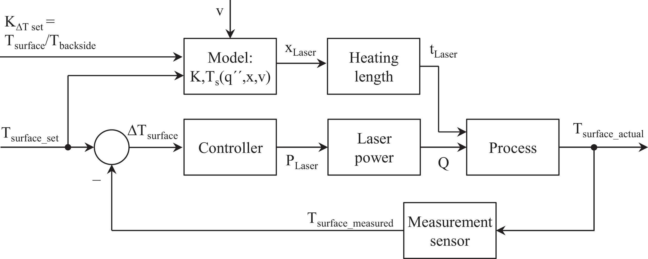
Model-based control for simultaneous control of surface temperature and thermal gradient.
Closed-loop control of thermal gradients
In order to be able to react to external disturbances, closed-loop controls are preferred over conventional control loops. Figure 12 introduces a closed-loop control, which utilizes the backside temperature of the tape; information which is rather easy to obtain by contact-free pyrometers. The pyrometers could be placed shortly after the bonding process behind the pressuring roller. This control only works under the premise that the backside of the tape is above the ambient temperature, meaning the process is run at Fo > 0.2. Heat has to accumulate in the tape. Stronger thermal gradients, where heat does not reach the back of the tape, are impossible to be detected.
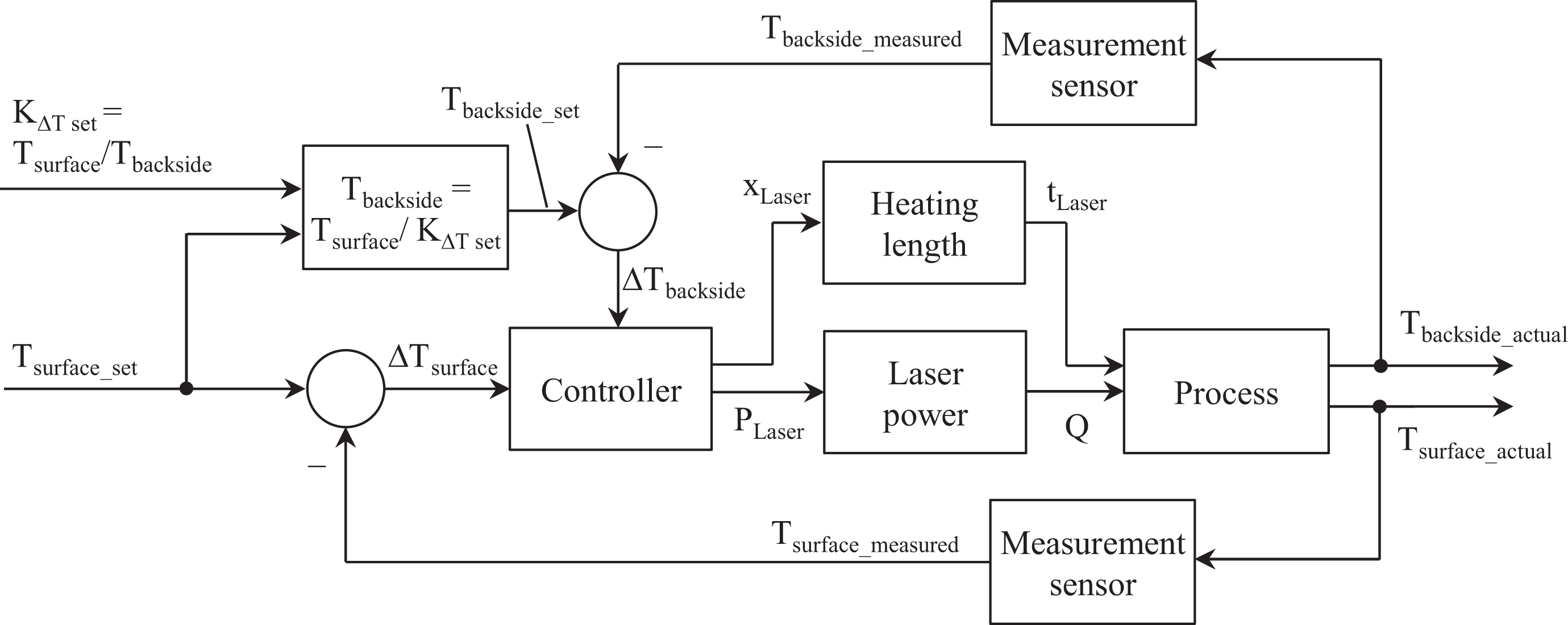
Closed-loop control for simultaneous control of surface temperature and thermal gradient in laser assisted tape placement. Feasible for Fo > 0.2, when heat reaches the backside of the tape.
Information about the temperature distribution from inside the tape seems to be even more suited for the control. Thermography of the part during the cooling phase may be a possible sensor technology to generate this information. For both control loops, the question arises how to attain adaptability in the heating length. Two high-power laser technologies were identified: VCSEL 41 and diode laser with motorized zoom homogenizer. 32 VCSELs enable the adaptation of the heating length by independently controllable emitter blocks. The emitter blocks are placed next to each other in a parallel configuration. This leads to very long heating lengths and high overall power. Current VCSEL technology offers laser intensities of 1.2 W/mm2 maximum (compare Figure 10). Therefore, they seem to be applicable for all desired surface temperatures (and temperature ratios) in tape processing, since with increased heating length, the optimum operation point can be reached. The second identified adaptable laser technology is diode lasers with additional zoom homogenizers. These zoom homogenizers are motorized and can therefore change the irradiated field over time and space.
Summary and conclusions
This article presented a simplified model for the transient thermal analysis of laser-assisted thermoplastic tape placement. Feasible model simplifications were summarized and novel simplifications for the cooling behavior were introduced. In order to solve the derived thermal problem, analytical solutions were identified and applied. These equations were used for a general analysis of the process. It was shown that heat accumulation is a crucial phenomenon, especially in thin tapes and at low processing speeds. By use of the Fourier number, a limit case was derived, which describes the critical process settings for the occurrence of heat accumulation. Furthermore, it was shown that processes at high speed and high laser intensity (with equal final surface temperature) lead to significant thermal gradients. Those gradients lead to rapid internal cooling by conduction in the cooling phase and to a significant narrowing of the molten polymer pool. The gradients may increasingly occur in practical use, because of economic pressure for higher material throughput, in combination with higher available laser power on the market. Therefore, an equation was derived for the temperature ratio between backside and surface of the tape, in order to obtain a control diagram, which describes how thermal gradients can be influenced by an additional manipulated variable: the laser heating length. Two laser technologies were identified, which enable an adaptation of the heating length: VCSELs and diode lasers with motorized zoom homogenizers. There is the potential that with controlled heating lengths, combined with the fast switching ability of lasers, the current technological limits of tape placement can be improved in terms of processing speed. In general, controlled temperature distributions could be an important step for a reliable manufacturing of parts with structural integrity.
Footnotes
Acknowledgments
The authors wish to thank the German Federal Ministry of Education and Research (BMBF) for the financial support granted to conduct this study within the Aachen Research Campus Digital Photonic Production (DPP). Special thanks are due to the students supporting the research, colleagues of Fraunhofer IPT, AZL, Philips Photonics, and the Chair for Technology of Optical Systems (TOS) for the valuable discussions and inspiring cooperation, which led to the content of this article.
Declaration of Conflicting Interests
The author(s) declared no potential conflicts of interest with respect to the research, authorship, and/or publication of this article.
Funding
The author(s) disclosed receipt of the following financial support for the research, authorship, and/or publication of this article: This work was financially supported by the German Federal Ministry of Education and Research (BMBF; grant no. 13N13476).