
Abstract
Automated fibre placement (AFP) is a relatively new process for the manufacturing of composite structures. Among many attractive features, it provides high-speed of material deposition, more repeatability in terms of quality of the part, less labour intensive (as compared with traditional methods of manufacturing such as Hand Lay-Up), less waste and the ability to transition more seamlessly from design to manufacturing. AFP can be used to process both thermoset composites and thermoplastic composites. Thermoplastic composites processing holds many potential benefits. This is because if the process is done right in producing parts with good quality, it is fast since it does not require a second process such as curing in an autoclave or oven. For the purpose of comparison of performance and for design, it is necessary to determine the mechanical properties of laminates made using this process. However, there are challenges in making flat coupons for the purpose of testing for mechanical properties. This article presents these challenges and the procedure developed to make flat laminates using a simple AFP machine. Mechanical properties of these laminates are also determined and compared with those obtained from laminates made using conventional autoclave moulding.
Keywords
Introduction
The increasing use of composites in making many important engineering structures such as airplane fuselage, blades for wind turbines and automotive components requires that the manufacturing of these structures be done at faster rate and lower cost. Manufacturing techniques such as Hand Lay-Up cannot produce a deposition rate fast enough for these new demanding applications. The repeatability of the quality and performance of the part is an important requirement. There is also a significant amount of material waste in the traditional method of manufacturing. This in turn increases cost.
One method of automated composite manufacturing is filament winding. Nejhad et al. 1 –4 have studied filament wound structures made of thermoplastic composites. The drawback of filament winding is the inability to wind over concave surfaces.
Over the past few years, many new methods for automated manufacturing of composite structures have been developed. Two common methods are automated tape laying (ATL) and automated fibre placement (AFP). The similarity between these two methods is that they use automation for the deposition of the composite material onto the surface of the mould. For differences, ATL handles wider tapes (up to 304.8 mm (12 in.) wide), whereas AFP handles relatively narrower tapes (from 6.35 mm (1/8 in.) to 25.4 mm (1 in.) wide). Since the tape width is larger, ATL can provide faster material deposition rate as compared to AFP. To make up for the narrower tape, AFP machines can have heads that can handle multiple tows. By handling narrower tapes, AFP machines can have the capacity to steer the fibres. This fibre steering can allow the fibre orientation to change within one particular ply in the laminate. Besides, for the processing of thermoplastic composites, where in situ heating to melt the tape is required, the focus of the heat source on narrower tape is better than on wider tape.
The focus of this article is on thermoplastic composites made using AFP. The advantages of thermoplastic composites over thermoset composites, such as no worry about shelf life, good ductility, recyclability, and so on, are well known. The disadvantages of high viscosity, which results in difficulties in processing and in void occurrence in the final laminate are also well known. The common method of making thermoplastic composite parts is by compression moulding using a compression press or an autoclave. 5 Normally, laminates with good quality can be obtained using these processes. However, due to the limitation of the size of the press or an autoclave, often only parts of small dimensions can be made. With the advent of AFP, thermoplastic composite parts of large dimensions can be made. It is also expected that the issue of high viscosity can be handled by the high-level heat source to melt the resin at the nip point. However, it is not clear whether laminates made using AFP are of comparable quality to parts made using an autoclave. In order to compare the quality of these laminates, coupons need to be made from panels manufactured by different methods and mechanical tests need to be carried out. However, it was found that there are many challenges in making flat panels out of thermoplastic composites using AFP. This article addresses how these challenges have been overcome, and the mechanical properties of laminates made by AFP are presented in comparison with those made using autoclave moulding.
Challenges in making flat laminates using thermoplastic composites and AFP
AFP for thermoplastic composites
In order to understand the challenges in making flat laminates using thermoplastic composites and AFP, it is necessary to understand the process of AFP for thermoplastic composites. Figure 1 shows a schematic of the AFP process for thermoplastic composites. The process consists of many stages (Figure 2). In order to understand the process, here one follows a segment of thermoplastic composite tape to see what happens to it, as follows.
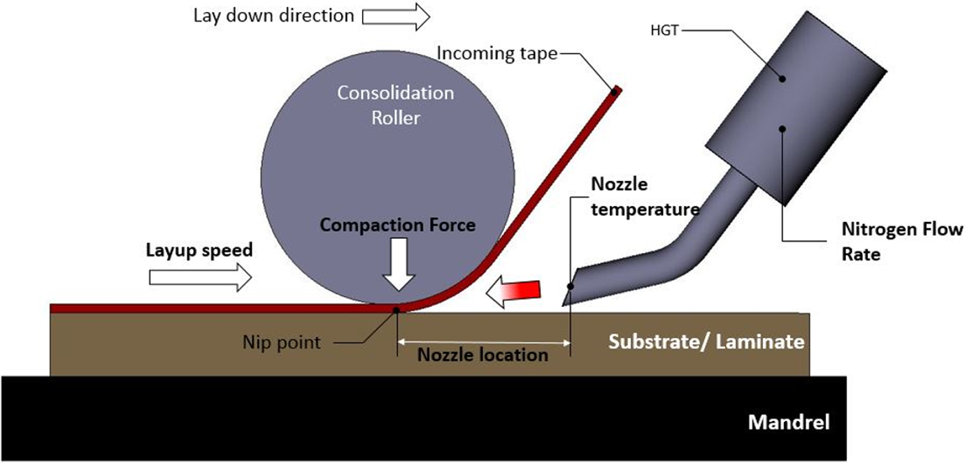
Schematic of the AFP process for thermoplastic composites.
Stages in the AFP for thermoplastic composites.
Stage A
The AFP process for thermoplastic composites can be considered to begin with the feeding of the thermoplastic composite tape segment toward the nip point. The nip point is the point where the roller presses the tape against the mandrel (or substrate) and where the local heat is concentrated. The tape is made of either carbon or glass fibres pre-impregnated with thermoplastic resin such as polyetheretherketone (PEEK), polyetherketoneketone (PEKK), polyphenylene sulfide (PPS) or polyetherimide PEI. The tape has a thickness of about 0.13 mm. The tape is fed towards the nip point by a feeding mechanism of the AFP machine. The difference between AFP and filament winding is that in filament winding, the tape is held in tension, while in AFP the tape may not be in tension. The tape may or may not be preheated at this stage. If the tape is preheated, the amount of heat applied at the nip point can be less and the probability for complete melt at the nip point is better. However, too much heating at this stage may soften the tape and it may buckle due to the compression along its length due to feeding. The effects of preheating have been studied in the literature. 6 –9
Stage B
The tape segment is at the NIP point. External heat source (either hot gas torch or laser) is applied to melt the tape segment. The roller applies pressure on the melted tape segment to bond it to the substrate below. The substrate can be the mandrel (in the case of the first layer) or previously deposited layers (in the case of subsequent layers). The tape segment is squeezed due to compression along its thickness. Sufficient time should be allowed so that bonding with the substrate can take place. Simultaneously, the mandrel is moving in the opposite direction with the feeding direction of the tape. Many phenomena take place: Due to compression, tape thickness may be reduced, and its width may be increased. Depending on the temperature of the substrate, heat may be transferred from the melted tape segment to the substrate below. Viscous flow of the resin may occur due to permeability in the fibre network and to the relative motion between the tape segment and the substrate. Bonding due to molecular reptation across the interface of the different layers needs to take place to assure good quality of the part.
This stage B may be labelled round 1 for heating and compression along tape thickness.
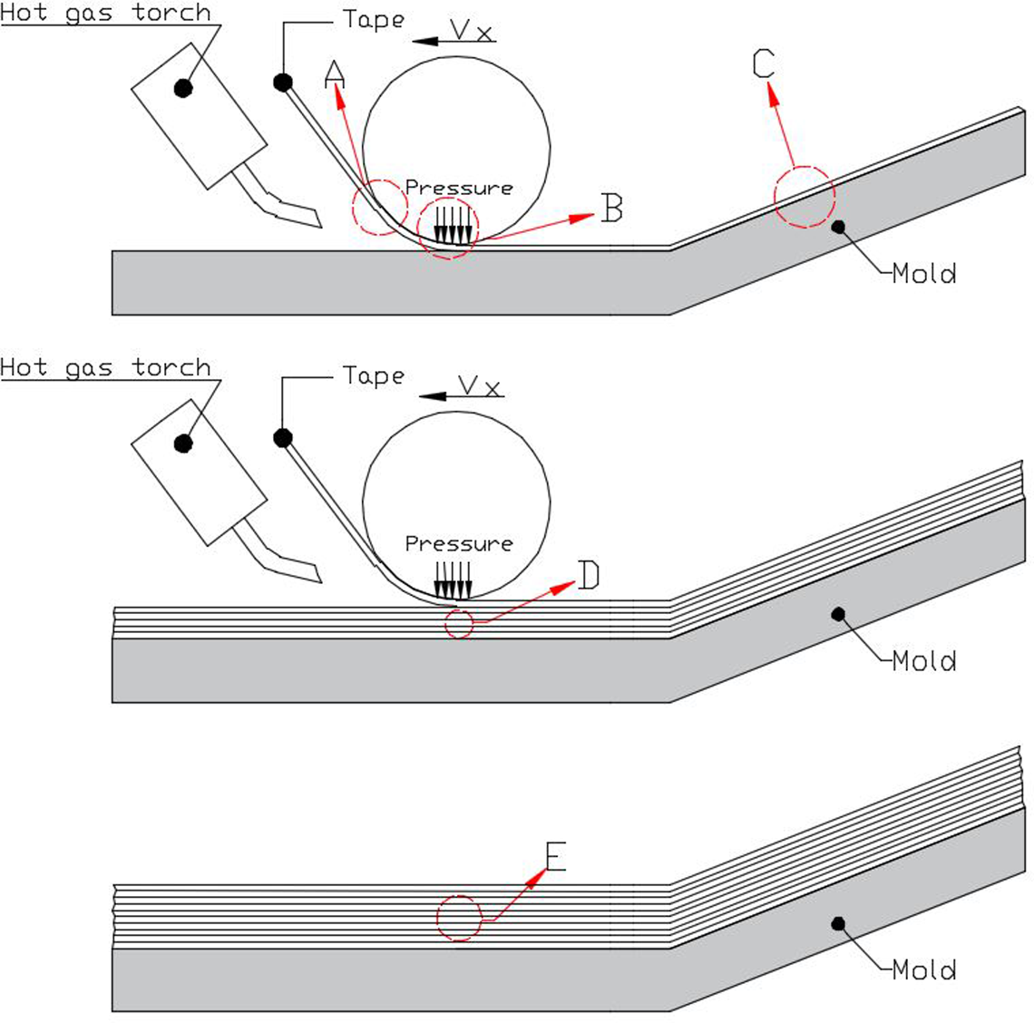
Stage C
The roller and the focus of the heat source go past the tape segment under consideration. Due to the lower temperature in the surroundings (ambient air above the tape segment and the cooler substrate), heat may be transferred out of the tape segment. Also, the removal of the compression (along tape thickness) from the roller will allow the stresses in the tape segment to relax. Viscoelastic behaviour occurs over a certain temperature range upon cooling.
If only one layer of tape is deposited onto the mandrel to make a one-layer laminate, then the tape and the surrounding will cool down to room temperature. The mismatch in thermal expansion coefficients along different directions in the tape, temperature gradient, shrinkage and crystallization can give rise to residual stresses in the final part. 2
Stage D
If more than one layer is required to make the laminate, the roller and heat source will come back to deposit subsequent layers over the tape segment under consideration. At this time, the tape segment will be subjected to high temperature and compression in the thickness direction again but maybe at lower intensities. Bonding between the tape segment and the new segment to be deposited will be required.
This stage D may be labelled round 2 for heating and compression along tape thickness.
Depending on the number of layers in the laminate, many more rounds of compression and heating will take place.
Stage E
Similar to stage C, the roller and heat source go away from the tape segment and the tape segment together with one other (or more) segment(s) above or below will start to cool down. Due to the fact that they were deposited at different times, the temperature of different layers along the thickness of the laminate may be different. If the temperature of a certain layer has dropped to be below its glass transition temperature (T g), the modulus of that layer is high. Upon cooling, each layer shrinks. If the layer on top shrinks more (because of its higher temperature) while the layer below shrinks less (because of its lower temperature), distortion due to bending will occur. This is the inherent problem that gives rise to distortion in the laminate during manufacturing and this is the challenge for the manufacturing of flat laminates.
Figure 3 shows the different modes of distortion that may occur in a thermoplastic composite laminate made by AFP. Figure 4 shows the distorted laminate. The distortion is due to the reasons mentioned earlier along with the coupling between normal and shear behaviour in the laminate.
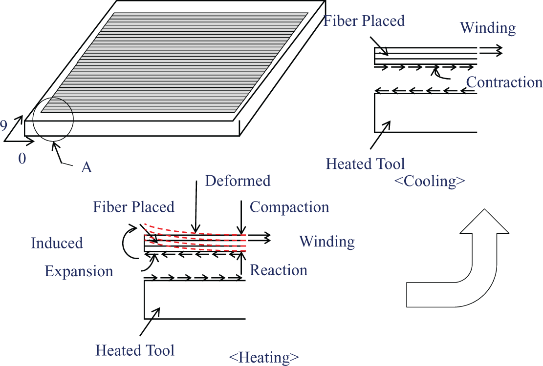
Different modes of distortion in a thermoplastic composite plate made by AFP. 10
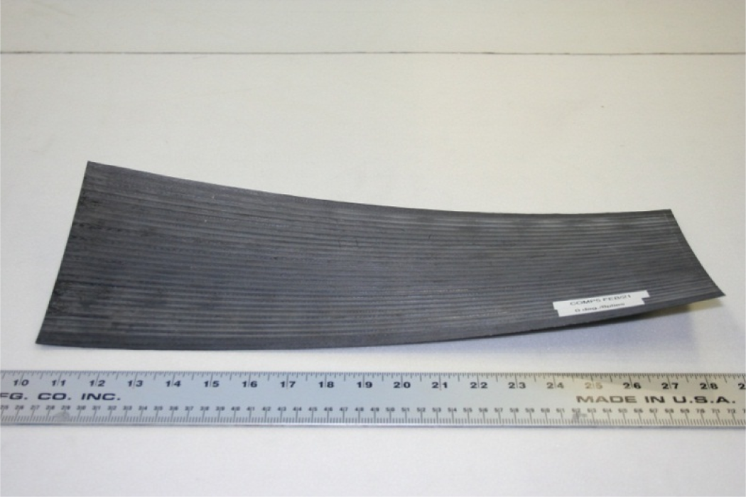
Distorted laminate.
The problem with making flat thermoplastic composite laminate using AFP may be rectified using a complicated head design. Lamontia et al. 11,12 showed that using multiple rollers (one roller in the hot zone for the deposition of the material and another roller in the cold zone for the consolidation of the material), it was possible to make flat laminates with good quality. For AS4/PEEK, the compression properties of laminates made by in-situ automated tape placement were comparable with those made by automated tape placement followed with autoclave treatment. The design of the head of the automated tape placement machine is very complicated and very expensive (on the order of several million dollars for the head alone). For simpler machines with only one roller 13 or with two rollers but simpler design, 14 the problem of a warped laminate occurs.
It is important to develop a method for the manufacturing of flat plates made of thermoplastic composites using AFP and a simple fibre placement machine. This will allow the characterization of the materials for comparison with those made using the traditional autoclave technique. The following section proposes a method for the manufacturing of flat plate laminates.
Procedure to make flat plate of thermoplastic composites using AFP
Hypothesis
It has been observed that the reason for the distortion of the plate is due to the interaction either between layers at different temperatures or between the layers and the mandrel. The cause for the interaction is due to the difference in thermal expansion between the different materials. One method to eliminate this problem would be to lay the composites on a heated mandrel, where the temperature of the mandrel is above the T g of the materials. All composite layers would be deposited, while the mandrel is above the T g of the material. After all layers have been laid, the whole assembly of layers and mandrel would be cooled down at the same time. In this way, there would be no significant difference in stiffnesses among the layers during cooling to give rise to distortion.
Experimental
The laminates were made using an AFP machine from Automated Dynamics (Figure 5). The robot arm has six degrees of freedom controlled by six servo motors. The robot and control units are made by Kawasaki [Kawasaki Robotics (USA), Inc. 28140 Lakeview Drive Wixom, Michigan 48393], and the head, which is used to lay down the composite material, is made by Automated Dynamics (2 Commerce Park Drive Niskayuna, NY 12309 USA). Stainless steel roller of 12.7 mm (0.5 in.) diameter and 17.8 mm (0.7 in.) wide is used. A heated steel mandrel was used. The material used was 6.35 mm (0.25 in) wide and 0.13 mm (0.005 in) thick, thermoplastic composite tape (AS4/PEEK) from CYTEC (5 Garret Mountain Plaza Woodland Park, NJ 07424).
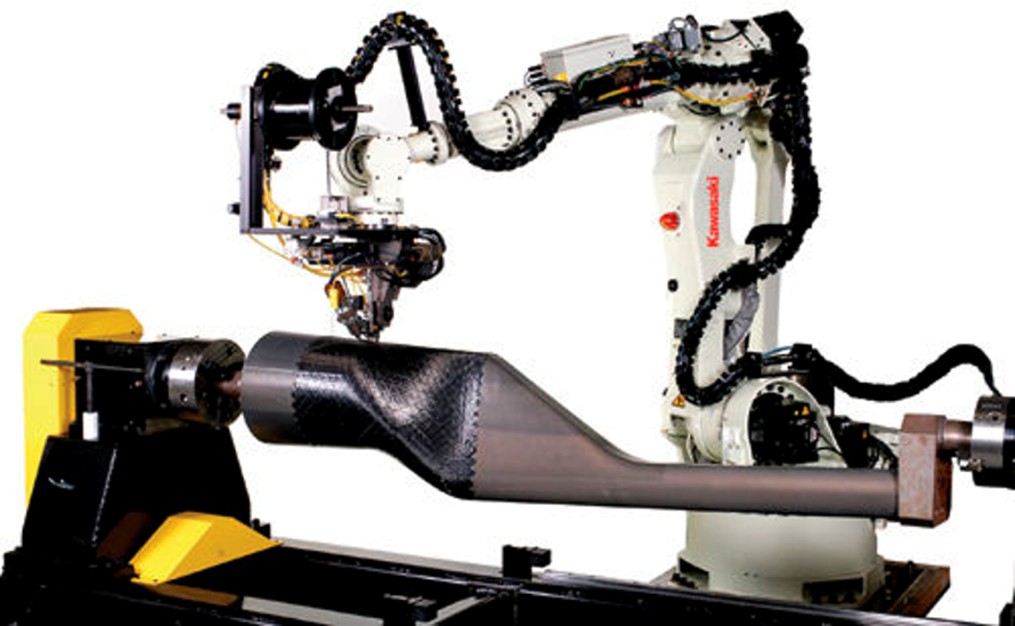
AFP machine from Automated Dynamics, at Concordia.
Figure 6 shows the temperature distribution on the heating table after laying the first ply. The temperature was measured using infrared camera. The heating table was set at 250°C, measured at the bottom surface. The temperature drops about 40°C from x = 0 to x = ±6 in. (152.4 mm) in x direction. In y direction, it drops about 40°C from y = 0 at the centre to y = ±5 in. (127 mm). From this temperature distribution, the size of the laminate was decided to minimize stress due to temperature difference. The chosen dimensions are 12 in. × 6 in. (304.8 mm × 152.4 mm), which is good enough to make samples for testing.
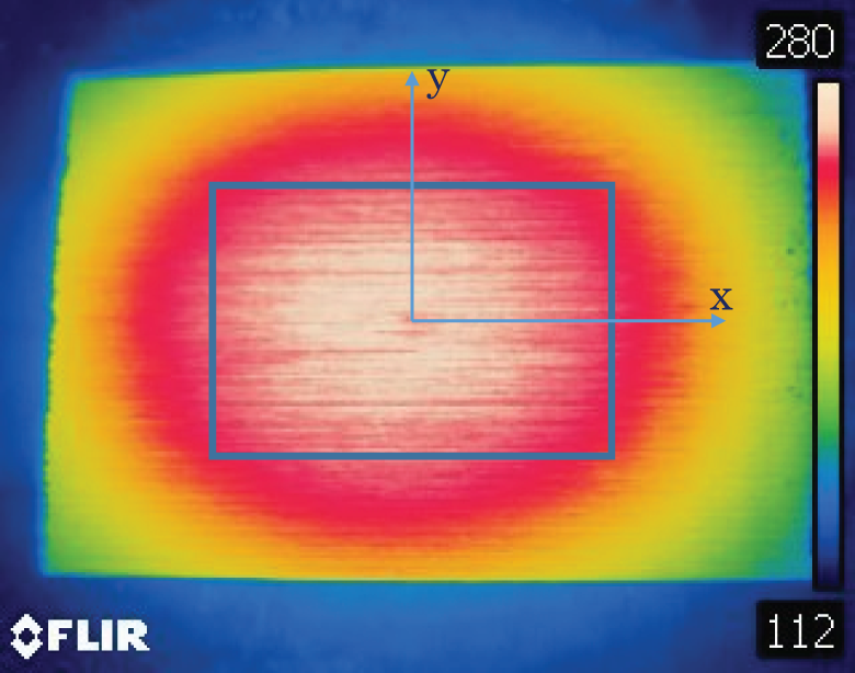
Temperature distribution on the heated table.
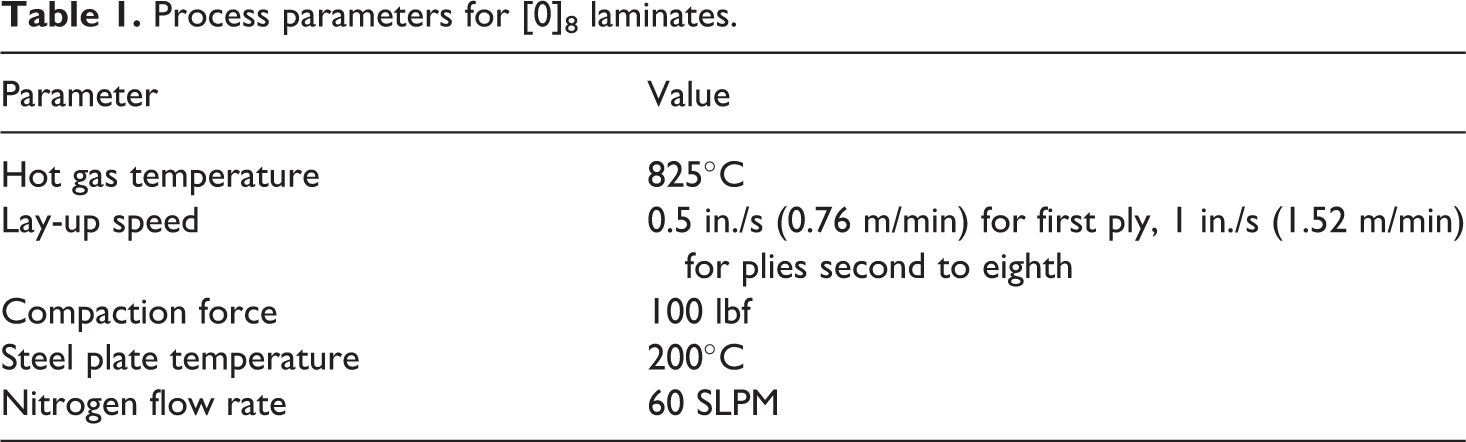
Three types of laminates were made: [0]8, [0]12 and [45/−45]2 s. The process parameters for the [0]8 laminates are shown in Table 1.
Process parameters for [0]8 laminates.
Processing parameters for the [0]12 laminates are similar to those in Table 1 up to layer number 8. It was found that as the number of layers increases, residual heat buildup in the laminate increases the temperature, making the layer softer. It is difficult to make the new layer adhere to the substrate when the substrate is too soft. As such, after layer number 8, cooling by compressed air was applied to the top layer before additional layers were added.
For the [45/−45]2 s laminates, the process parameters are the same as those of the [0]8 laminates. In addition, due to the fact that the roller is moving in a direction transverse to the fibre direction, if the substrate is too soft, ploughing occurs and defects arise. In order to avoid too much softening of the substrate, the mandrel temperature was set at 200°C for the first two plies and it was reduced to 150°C for the subsequent plies. Air cooling was also applied for the subsequent plies. Also, a caul plate was placed on top of the laminate, and allowed to reach steady state temperature before cooling down.
The configurations of the laminates are shown in Figure 7. It can be seen that flat laminates are obtained.
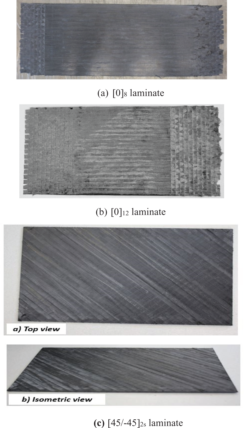
Appearances of AFP laminates. (a) [0]8 laminate, (b) [0]12 laminate and (c) [45/−45]2 s laminate. AFP: automated fibre placement.
Microscopic observations
One very important aspect of the quality of laminates made using thermoplastic composites is the appearance of voids. Laminates have low void content for the lower layers (close to the mandrel) of the laminate, while upper layers have more voids. The reason for this is because the lower layers were subjected to many passes and repasses of heat and pressure, while the upper layers were subjected to less repasses. The mechanism for this can be the migration of fibres due to repass compression build-up. To rectify this problem, one repass was carried out after the last layer has been deposited. Microscopic observation of the flat samples is shown in Figure 8. It can be seen that the samples have good quality and there is very little void content.
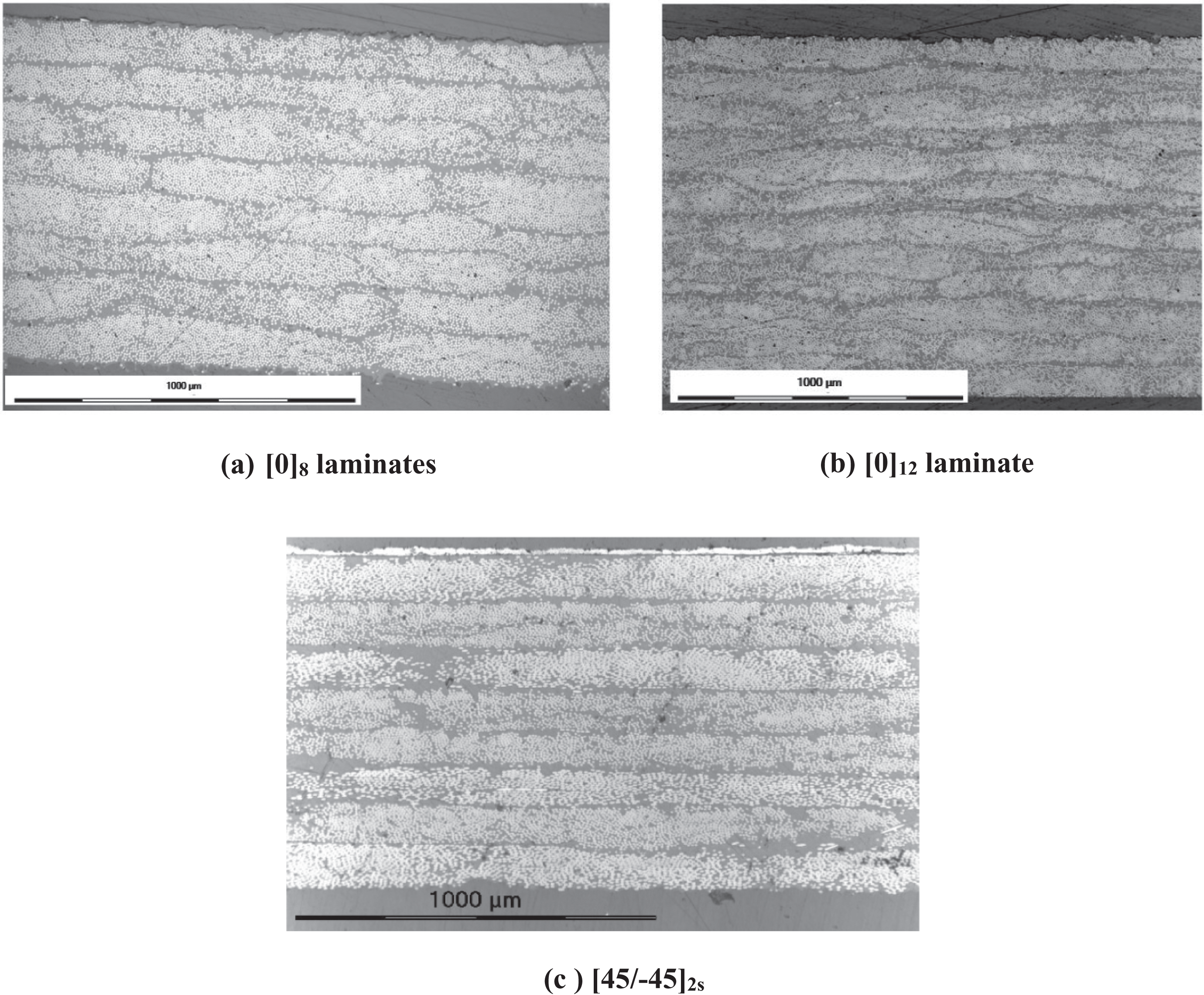
Microscopic views of the microstructures of the laminates. (a) [0]8 laminates, (b) [0]12 laminate and (c) [45/−45]2 s.
It is important to note that the speed of material deposition has an important influence on the quality of the laminate in terms of voids. The speed of material deposition in Lamontia et al. 11 was up to 5 m/min, while the speed used in the laminates in this article was 1.52 m/min. The speed depends on the design of the machine and whether one tow or multiple tows is placed at the same time. Industry would like to have higher speed for faster material deposition. In a recent work by Comer et al., 15 an AFP machine with laser heating was used. The lay-down speed was between 8 m/min and 12 m/min. However, the laminate has a large amount of voids and this resulted in lower mechanical properties as compared to laminates made using autoclave technique. The quality of the part depends on the speed of the process as well as the amount of heat and hence temperature history in the part leading to a narrow processing window to obtain a good-quality part. 7
Crystallinity
Crystallinity of the laminates depends on the rate of cooling. For semi-crystalline materials such as PEEK, a higher cooling rate leads to a lower degree of crystallinity and vice versa. The laminates made in this study were cooled naturally from 250°C to 90°C within 40 min, giving rise to an average cooling rate of 4°C min−1. Crystallinity of the final laminates was checked by differential scanning calorimetry. Figure 9 shows that there is no crystallization peak, indicating that the resin has reached its maximum level of crystallization.
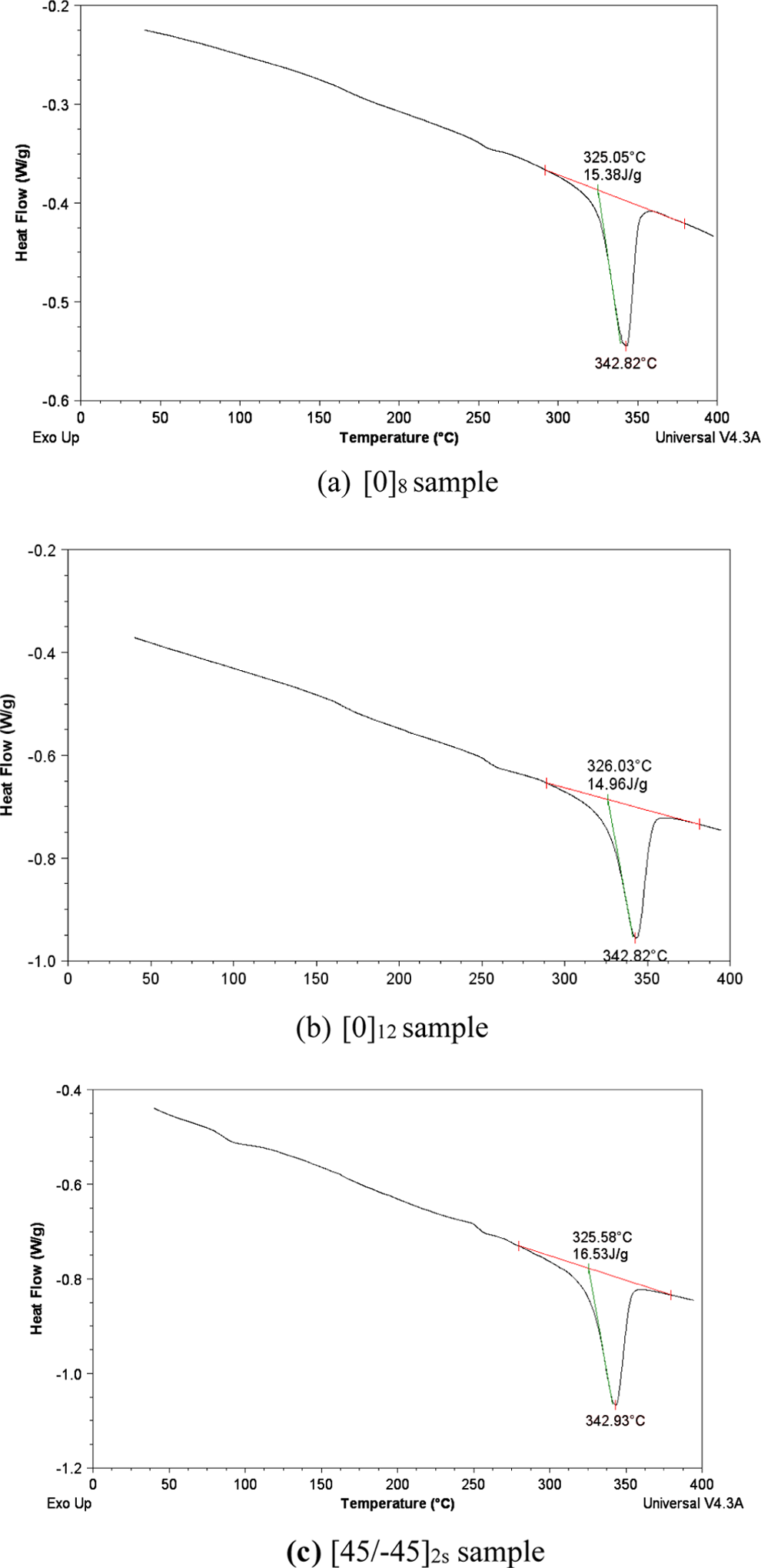
Crystallinity using DSC.
Mechanical properties of thermoplastic composites made by AFP
The samples were subjected to three types of mechanical tests: tensile, compression and shear. Tests were carried out using ASTM standards 3039-07, 16 ASTM 3410-03 17 and ASTM 3518, 18 respectively. Five replicates were carried out for each test.
Tensile test
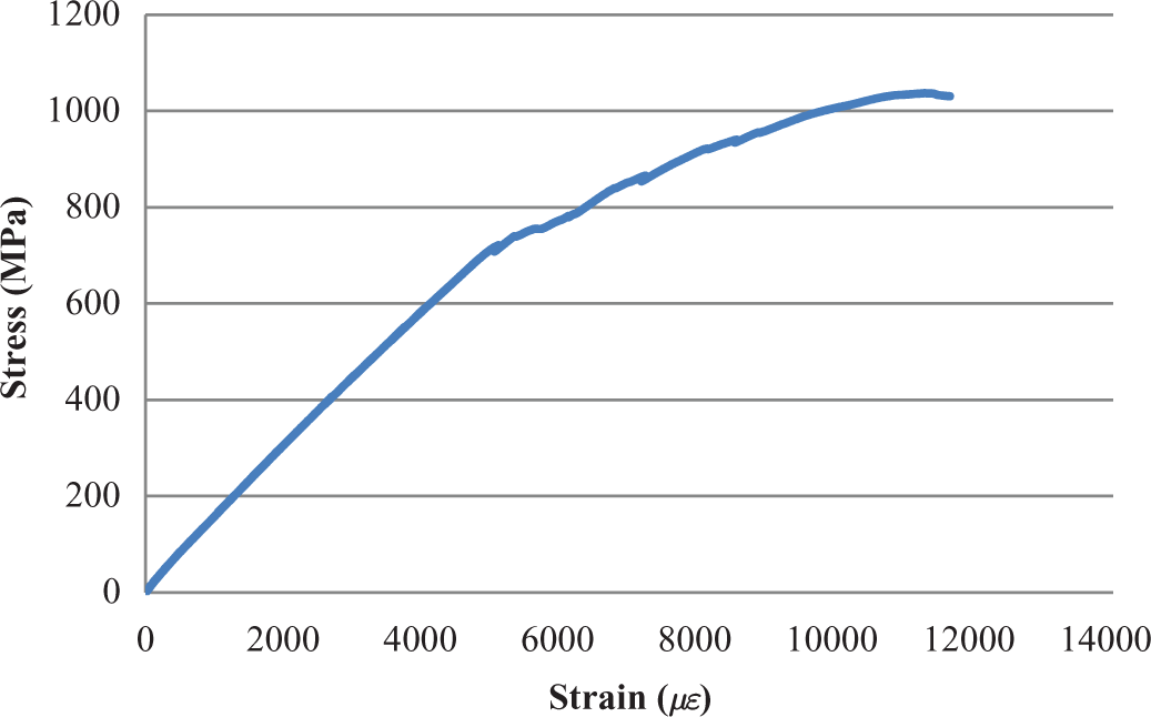
Figure 10 shows the stress–strain curve of the tensile test. During testing, it is noticed that delamination happened first, then followed by fibre fracture.
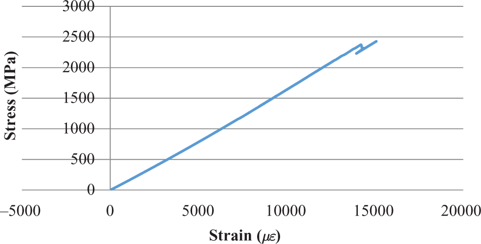
Stress versus strain curve for tensile test.
Table 2 summarizes the results of mechanical properties of laminates made by AFP. Results for samples made by autoclave technique obtained by Cai 10 are presented as a reference point for comparison. The processing procedure for the autoclave processed laminates is shown in Figure 11.
Mechanical properties of laminates made by AFP and by autoclave technique.
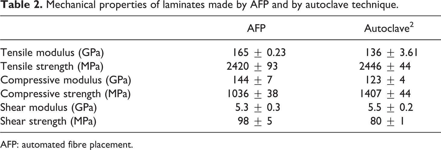
AFP: automated fibre placement.
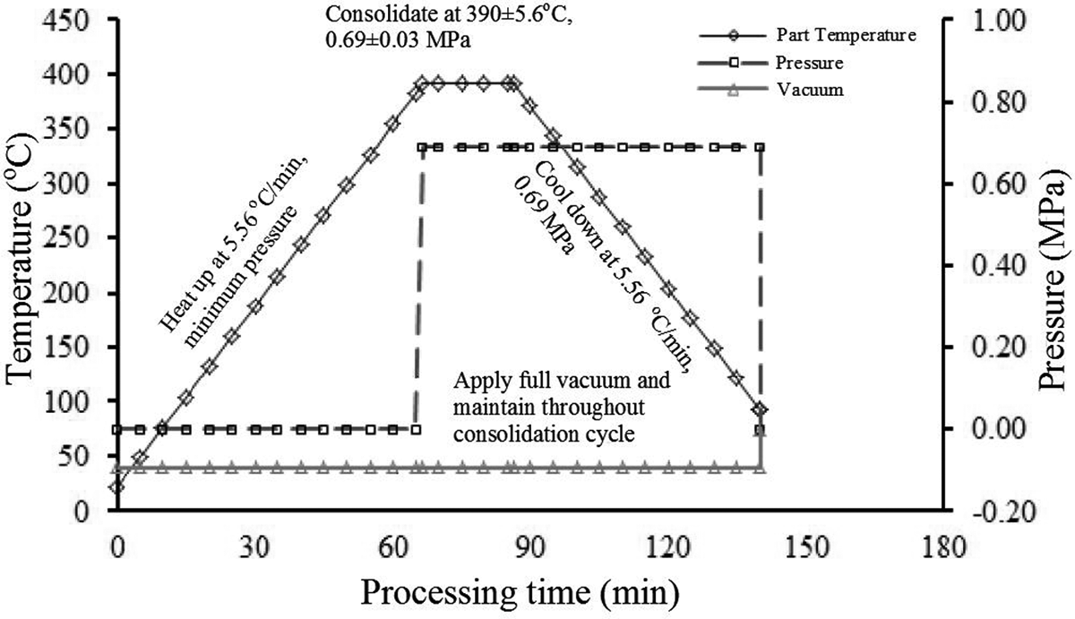
Processing procedure for autoclave consolidation of APC-2/AS4.
The average value of tensile modulus in the case of a laminate made by AFP is 165 GPa as compared to 136 GPa for laminates using autoclave. The tensile strength for a laminate made by AFP is 2420 and 2446 MPa for laminate made by autoclave technique. The difference in modulus can be explained by the reduction of thickness by 19% of laminates made by AFP. The fibre volume fraction (v f) of laminates made by AFP was measured using two-dimensional microscopic analysis. Its value is 61%. Even this v f is close to the value given by CYTEC, 19 the measurement of v f from prepreg tape using the same methods shows that v f of the prepreg varies in a large range and has the average value of 50%. Tensile strength was not increased by the same percentage as tensile modulus.
Compression test
Figure 12 shows the stress–strain curve of the compression test.
Stress versus strain curve for compression test.
The compression modulus for samples made using AFP is 144 GPa as compared with 123 GPa for laminates made using an autoclave. The compressive strength of samples made by AFP is 1055 MPa, while that of samples made by autoclave technique is 1407 MPa. The increase in modulus may be explained by the reduction in thickness. The reduction in compressive strength may be explained by microscopic observation, Figure 13 shows the microstructure appearance of two types of laminates. The figures show that for samples made by AFP, fibres are more wavy (in-plane waviness) than those made by autoclave technique. The waviness can be due to the penetration of the roller into the soft layers, spreading the fibres as well as the fibre migration from the top towards the mandrel, due to repass compression build-up. In addition, a better quality of samples made by autoclave technique is attributed to a more uniform pressure distribution in the case of autoclave processing.
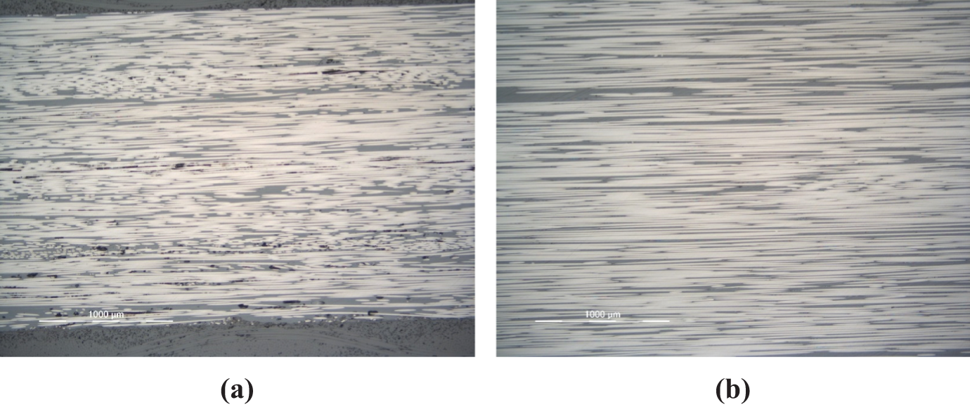
Microstructure appearance of two types of laminates (a) made by AFP and (b) made by autoclave technique. 20
In-plane shear test
Figure 14 shows the stress–strain curve of the in-plane shear test.
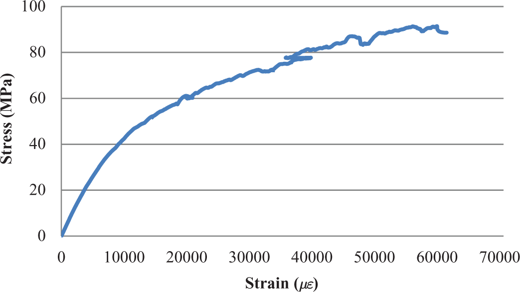
Stress versus strain curve for shear test.
The average value of shear modulus for laminates made by AFP is 5.3 GPa as compared to 5.5 GPa for laminates made using an autoclave. The shear strength of laminates made by AFP is 101 Mpa, which is 20% higher than the shear strength of laminates made by autoclave technique (80 MPa). However, shear strength of laminates made by autoclave technique was obtained with ASTM D5379 standard, while laminates made by AFP were subjected to ASTM D3518 standard. The difference of test conditions may create the different results.
Results obtained from other researchers
Table 3 shows the results of a few mechanical properties obtained by Lamontia et al. 11,12 and Comer et al. 15 Lamontia used a complex thermoplastic deposition head. The heating system uses nitrogen gas. In open hole compression (OHC) test, lay-down speed was not mentioned, but the maximum capacity of lay-down speed for their machine is 3.28 in./s (5 m/min). 11
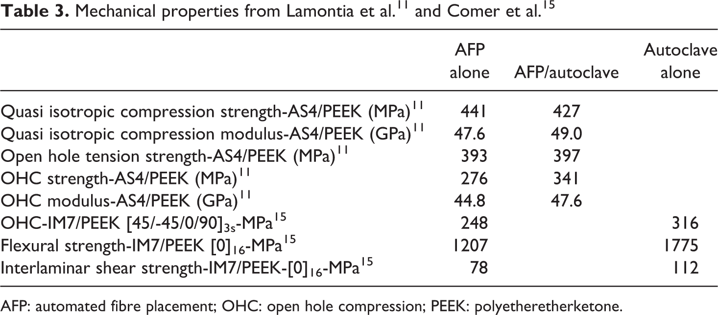
AFP: automated fibre placement; OHC: open hole compression; PEEK: polyetheretherketone.
Comer et al. 15 studied the mechanical properties of laminates of carbon/PEEK made by AFP using laser heating. Their rate of material deposition is 7.87 in/s (12 m/min), which is much higher than the rate of deposition used in this study (1 in./s or 1.52 m/min). However, their laminates have a large amount of void (2%) and the properties are lower than those made using an autoclave (interlaminar strength at 70%, flexural strength at 68% and OHC strength at 68%, of the corresponding values from laminates made using an autoclave).
Discussion
For the manufacturing of laminates using AFP, two factors affect the quality of the laminates; one is the speed at which the laminates are made and the second is the heat intensity as well as the preheater heat intensity. 7 The quality requires that a very small amount of voids exist (less than 1% for aircraft applications) and that the degree of crystallinity is high. It can be seen from the results obtained that it is possible to make laminates of good quality from different types of AFP machines. The speed to make these good laminates depends on the specific characteristics of the components of the AFP machine. The influence of some of these components is discussed below.
Heating system: Main heater type of heating system, preliminary heater
The main heat source for current AFP machine can be either hot gas or laser. Heat is diffused more using hot gas than laser heating. If hot gas is used, the roller material has to be able to withstand high temperature since the hot gas heats up the roller and the roller transmits the heat to the material. A steel roller is usually used for hot gas heating. Due to the high stiffness of steel, the roller in this case may have deeper penetration into the soft melted tape and substrate. This may create local waviness in the fibres as shown in Figure 13(a). If laser heating is used, softer roller material such as silicone may be used. This may reduce the local waviness problem. On the other hand, hot gas may be used to lay down wider tape, whereas laser heating may be limited in width due to the narrow focus of the laser beam. In addition, from the safety standpoint, laser is more dangerous and extra caution for shielding is required during operation.
Apart from the main heat source, secondary heat source (usually of infrared type) may be used to preheat the tape. This preheating can help to make the material reach melting more quickly when it enters the nip point. 7,8
Roller material, dimensions and number
As mentioned in item 1 earlier, the roller material can be made of a stiff material such as steel, or a soft material such as silicone, depending on the type of heat source. Wider rollers may be used to speed-up the material deposition, provided that the heat source can provide efficient heating over a wide band. Simple machines may have one roller that is used to apply pressure on the soft melted composite material for consolidation. If only one roller is used, voids may occur, particularly in the last few layers of the laminate. The voids can be suppressed by the application of one or more repasses. This slows the process. More complex machines may have more than one roller: one principal roller for the compaction at the nip point and one or more secondary rollers to apply compaction after the nip point event. In a way, the secondary roller(s) serves the function of the repass as in the case of a machine with one roller.
Heated or non-heated mandrel
For the manufacturing of flat plates, or curved shells where there are free edges, heated mandrels may be necessary to avoid the warpage problem as discussed earlier in this article. Heated mandrel also provides good bonding with the deposited layer. However, if the temperature of the mandrel is kept high during the whole process, the temperature of later layers can be very high, making these layers very soft. This can create problems where these layers are lifted off the surface of the substrate, creating defects. Cooling of these top layers is then necessary. For the manufacturing of surfaces of revolution such as cylinders where there are no free edges, the use of a mandrel at room temperature is possible, since the lack of free edge helps to avoid the warpage problem.
Speed of material deposition
From the economy point of view, the speed of material deposition should be as high as possible. However, this should not come at the compromise of quality of the laminates. There are many ways to increase the speed: one is to use wider tapes (which require wider heat source and wider roller), or multiple tows or tapes. Another method is to increase the speed of the machine. This is possible if the heat transfer aspect is sufficient to melt the material within a short time, and if the bonding between the layers can happen within a short time. 7
Amount of pressure
Pressure is required to compact the layers for consolidation. Pressure is also required to squeeze out the voids. Too much pressure may increase the waviness of the fibres, while too little pressure may not provide adequate compaction and consolidation.
Thickness of the laminate
The thickness of the laminate has an effect on the temperature of the top layers in the laminate. When a heated mandrel is used, the upper layers have increasing temperature. This can create soft layers that may stick to the rollers, creating defects. The temperature gradient across the thickness of the laminate has an influence on the rate of cooling. This in turn can influence the distortion of the laminate upon cooling.
Conclusion
In this work, it has been shown that it is possible to make high-quality laminates out of thermoplastic composites using a simple AFP machine. Procedures for making flat laminates using a simple AFP machine were described. The results from mechanical properties show that tensile and shear properties of laminates made by AFP are better than those of laminates made by autoclave technique. Specifically, tensile modulus in laminates made using AFP is 22% higher than that of laminates made using an autoclave, while tensile strength is almost the same. Compressive modulus of laminate made by AFP is 17% higher than that by autoclave technique. However, compressive strength is reduced by 25%. The improvement in tensile modulus and compression modulus can be explained by the reduction of thickness of laminates manufactured by AFP compared to those made by autoclave consolidation. The reduction in compressive strength may be explained by the increase in in-plane waviness of the fibres due to penetration of the roller into the laminate as well as fibre migration due to pressure build-up.
Apart from making good-quality laminates, one should also be concerned with the speed of the manufacturing since this has an influence on the economy of manufacturing. The speed depends on the specific characteristics of different components of the AFP machine and is determined by a processing window analysis.
Footnotes
Declaration of conflicting interests
The author(s) declared no potential conflicts of interest with respect to the research, authorship, and/or publication of this article.
Funding
The author(s) disclosed receipt of the following financial support for the research, authorship, and/or publication of this article: The financial supports from the Natural Sciences and Engineering Research Council of Canada (NSERC) through the NSERC Industrial Chair program, Bombardier Aerospace, Bell Helicopter Textron Canada Ltd. and Concordia University are appreciated.