
Abstract
Carbon fiber reinforced thermoplastics (CFRTPs) have high potential in high-cycle (1 min) molding as a weight-reducing material for the mass production of automobile components. However, residual voids in CFRTPs lead to diminished and unstable mechanical properties; therefore, the effective quantification of the void content in CFRTP products is necessary for developing an affordable system for mass production. In a previous study, we demonstrated that the X-ray attenuation coefficient decreases with increasing void content; thus, measurements of X-ray attenuation coefficients can be used to estimate the void contents of CFRTPs. In this study, we first investigated in detail the soft X-ray attenuation coefficients of completely impregnated composite materials with three different thicknesses; we observed that the attenuation coefficients decreased with increasing composite thickness, even though they should be independent of the thickness according to the Beer–Lambert law. We next demonstrated that although no correlation exists between the X-ray transmittance and the apparent attenuation coefficient of six composites with various void contents, the true attenuation coefficient modified to account for void content exhibits a good linear relationship with the X-ray transmittance, same as fully impregnated composites. Using the approximation line between the X-ray transmittance and the modified attenuation coefficient of CFRTP, we estimated the void content on the basis of the difference between the apparent and true X-ray attenuation coefficients. The average difference in void content determined by conventional hydrostatic weighing and that determined by the proposed X-ray transmittance method was 0.43%. We therefore concluded that the void content of CFRTPs of any thickness can be estimated nondestructively using soft X-rays.
Introduction
Carbon fiber reinforced plastics (CFRPs) have attractive properties such as high specific rigidity and high specific strength. CFRPs are a class of promising lightweight materials with potential applications in the aerospace 1,2 and automotive industries. 3,4 Consequently, the literature contains numerous studies related to cost reduction, processing methods such as molding 5 and welding 6 for mass production and recycling 7 of CFRPs.
CFRP intermediate materials are produced by impregnation of carbon fibers with resin; CFRP thermosetting resins (CFRTSs) are distinguished from CFRP thermoplastic resins (CFRTPs) by the type of matrix resin. For CFRTSs, intermediate materials such as prepreg are produced at a relatively high speed using low-viscosity matrix resins. However, the molding cycle of CFRTSs ranges from a few minutes to few hours and involves a chemical curing process. Hence, rapid-curing thermosetting resins have been developed to shorten the molding cycle. 8
In contrast, CFRTPs solidify without a chemical curing process. Consequently, the molding cycle of CFRTP can be less than 1 min. However, because the viscosity of melted thermoplastic resins is substantially greater than that of thermosetting resins, the impregnation of reinforcement fiber with thermoplastic resins requires more expensive devices or longer impregnation times. Thus, nowadays, the relationship between reducing costs and achieving well-impregnated composite materials is a trade-off. Impregnation status drastically affects the mechanical properties of composite materials. Consequently, researchers have extensively investigated methods 9 –12 to improve the impregnation status, which is correlated with the void content. In general, quantifying the void content of CFRP products requires long analysis times; thus, an effective and a rapid technique 13,14 has been studied for the adoption of CFRPs for the mass production of automotive components.
Equation 1, as presented in ASTM D2734 standard, 15 is the most commonly used method for quantifying the void content of CFRPs:

where Vvoid is volume fraction of void, ρ is density of composite, VCF is volume fraction of carbon fibers, ρCF is density of carbon fibers, Vr is volume fraction of matrix resin, ρr is density of matrix resin, WCF is weight fraction of carbon fibers, and Wr is weight fraction of matrix resin.
This equation implies that the void content can be calculated from the results of measurements of the density of composites when the density of the carbon fibers and resin and their weight fractions are already known.
Void content can also be measured by another method using image analysis to judge void regions and other regions in cross sections of composites, as described in standard ISO 7822. 16 For evaluating the void contents nondestructively, as is necessary in a continuous production environment, these methods are not suitable. Observation by X-ray three-dimensional (3-D) computer tomography (CT) scanning is gaining popularity as a nondestructive method for measuring void content. Numerous studies 17 –21 involving the application of X-ray 3-D CT scanning to composite materials have therefore been reported. However, the method is difficult to use for continuous measurement in actual production facilities because the instrumentation is expensive and long analysis times are required.
By contrast, evaluations using X-ray transmittance have become practical. Soft X-rays have low energy, and radiation safety regulations to not restrict their use to isolated areas. Thus, unlike general X-rays, soft X-rays can be used in production facilities. An X-ray thickness gauge 22 –24 based on this principle is already available for contactless measurement of the thickness of materials such as resins or metal films and is applicable to resin plates as thick as 4 mm, aluminum foils as thick as 0.2 mm, and copper foils as thick as 0.1 mm.
For the measurement of thickness using X-rays, the relationship between X-ray transmittance and thickness is shown in equation (2); this equation is also applicable to general X-rays:

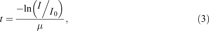
where I is transmitted X-ray intensity, μ is X-ray attenuation coefficient, I0 is initial X-ray intensity, t is thickness, and I/I0 is X-ray transmittance.
Equation (3), derived from equation (2), indicates that the thickness of a material can be obtained nondestructively through measurements of transmittance when the X-ray attenuation coefficient of a material is already known. With this approach, soft X-ray transmittance is mainly used for voidless materials and not for evaluating the void content in composite materials. In this study, we investigated the void content in composite materials as a function of their impregnation status using soft X-ray transmittance as a nondestructive method.
Experiments and methods
Sample preparation
We prepared polypropylene (PP) matrix prepreg using TR50S carbon fiber (tensile modulus: 240 GPa, tensile strength: 4900 MPa) produced by Mitsubishi Rayon Co., Ltd (Japan). The carbon fiber areal weight and the thickness of the prepreg were approximately 75 g/m2 and 0.1 mm, respectively. For our fundamental impregnation study, Mitsubishi Rayon specially provided partially impregnated prepreg, called “semi-preg,” which they manufactured by changing the processing speed. Figure 1 shows the cross section of the original semi-preg. We made several carbon fiber reinforced PP (CF/PP) plates composed of prepreg and semi-preg.
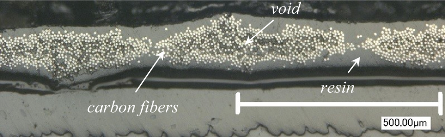
Cross section of the original CF/PP semi-preg.
For thermoplastic prepreg, three types of quasi-isotropic CF/PP plates were consolidated using an autoclave; their properties are reported in Table 1. The laminated prepregs were heated to 230°C with a heating rate of 4°C min−1 and they were maintained at 230°C for 15 min. Then, they were cooled with cooling rate of 4°C min−1 under a nitrogen pressure of 0.7 MPa in an autoclave. This autoclave condition is sufficient for obtaining fully impregnated PP matrix composites.
Thickness or lamination of sample.
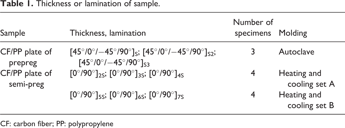
CF: carbon fiber; PP: polypropylene
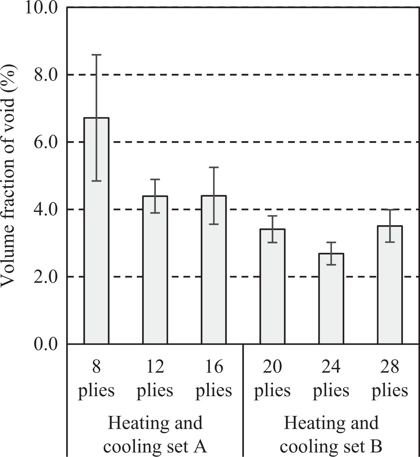
For thermoplastic semi-preg, six types of cross-ply CF/PP plates were consolidated using a heat-and-cool molding system; their properties are also reported in Table 1. Two sets of conditions for heat-and-cool molding were selected to prepare composite plates with different void contents presented in Figure 2. Three types of composites with 8, 12, and 16 plies were molded under condition set A, where the composites were heated to 180°C under a pressure of less than 0.1 MPa and cooled to 80°C under a pressure of 0.5 MPa. Three residual composites with 20, 24, and 28 plies were molded under condition set B, where the composites were heated to 180°C under a pressure of 0.1 MPa or less and cooled to 80°C under a pressure of 2.0 MPa. These two conditions were determined to obtain PP matrix composites with different amount of voids. Detailed information for all materials is reported in Table 1.
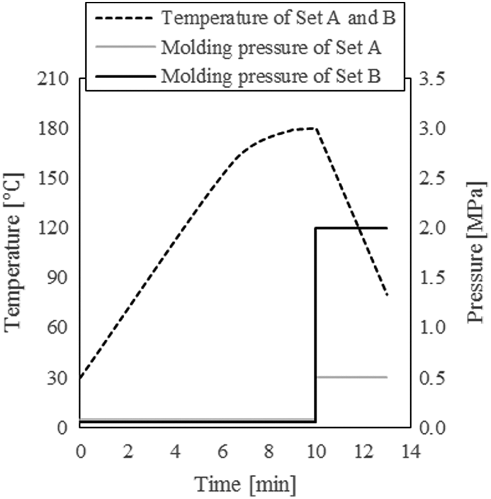
Heating and cooling conditions for composites of CF/PP semi-preg.
Measurement of X-ray transmittance and attenuation coefficient
The width and length of each specimen were 25 mm and 80 mm, respectively. An X-ray thickness gauge (AccureX Jr., FUTEC Inc., Japan) was used to measure soft X-ray transmittance. Figure 3 shows a schematic of the X-ray thickness gauge. The target material of the soft X-ray tube was tungsten. The target voltage of the tube was 14.5 kV and the mean X-ray energy generated from the tube was approximately 10 keV. To elucidate the effect of the target material and its voltage on X-ray transmittance, we used two other soft X-ray tubes; the results obtained using these tubes are shown in Appendix 1. The measurement accuracy of transmittance from the tungsten (W)/14.5 kV tube is the highest for the void content because it generates the highest X-ray energy among three X-ray tubes. Specimens 80 mm in length were scanned at intervals of 1 mm for the measurement of the X-ray transmittance of the whole specimen. For the calculation of the average thickness t of the specimens, the thickness of the specimens was measured at intervals of 5 mm using a micrometer. The X-ray attenuation coefficient was obtained by equation (4), which is derived from equation (2):
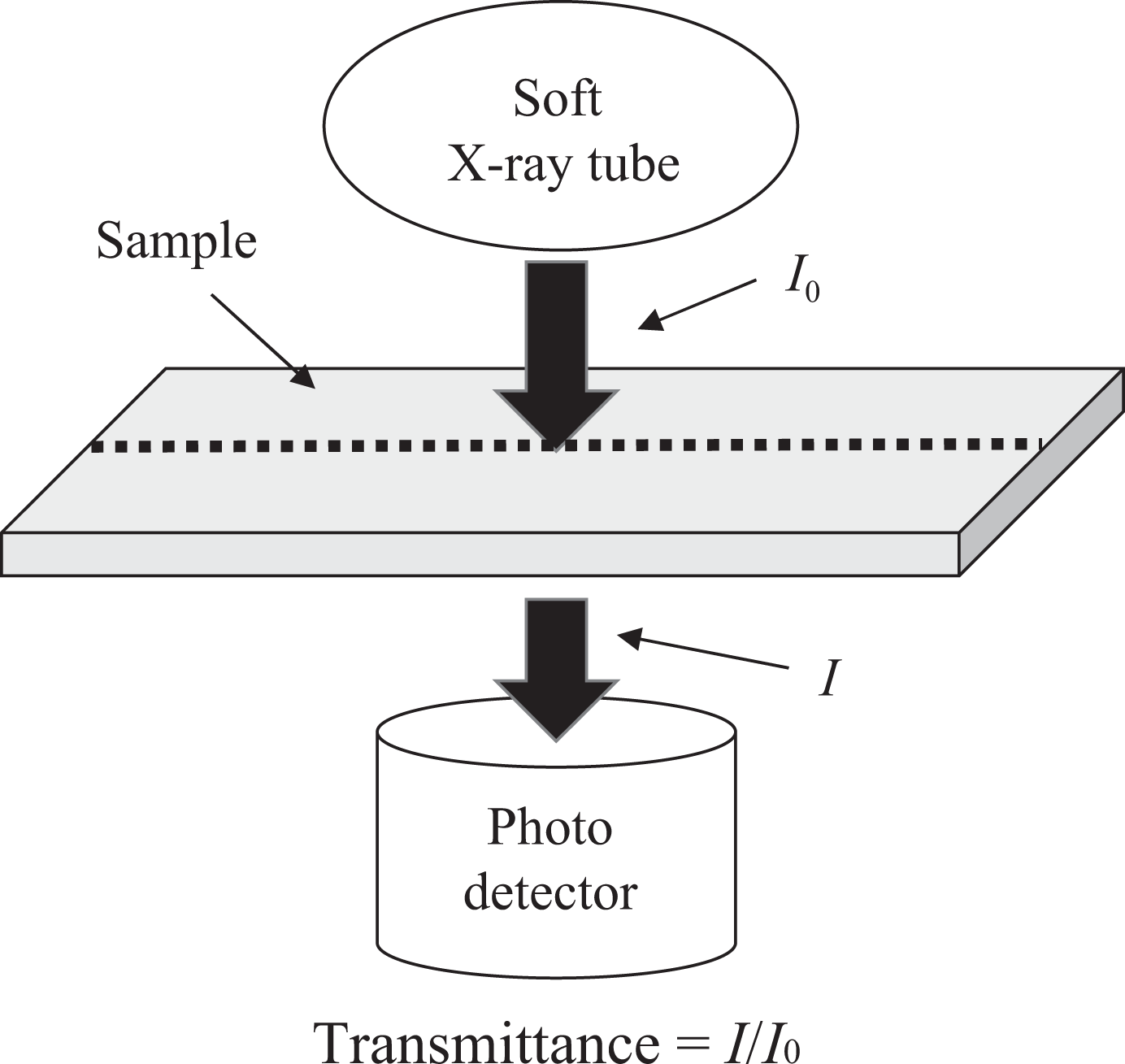
Schematic of the X-ray thickness gauge.
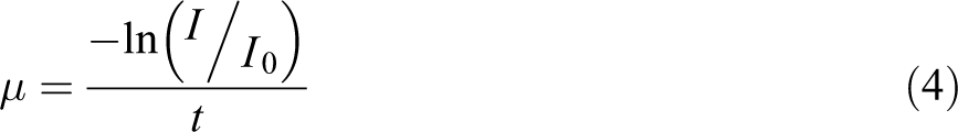
Figure 4 presents a sample calculation of the X-ray attenuation coefficient for one specimen.
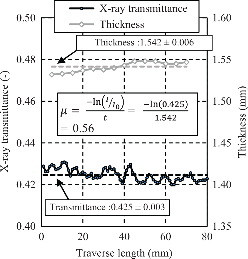
An example of the X-ray attenuation coefficients of a 16-ply CF/PP prepreg composite specimen.
In the case of CF/PP semi-preg samples that include voids, we redefine several technical terms for clarity. When tapp is the apparent thickness measured by micrometer, the apparent X-ray attenuation coefficient μapp is defined as shown in equation (5). When ttrue is defined as the thickness without the void in semi-preg, as in equation (6), the true X-ray attenuation coefficient μtrue is obtained from equation (7):
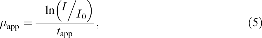

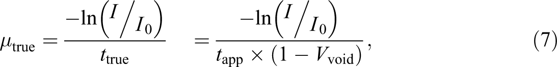
where tapp is apparent thickness, μapp is apparent X-ray attenuation coefficient, ttrue is true thickness, and μtrue is true X-ray attenuation coefficient.
Measurement of true void content
To confirm the true void content of the specimens, the density of each specimen was measured by the hydrostatic weighing method described in ASTM D792 25 standard and represented in equation (8):

where ρhyd is density by hydrostatic weighing, WA is weight in air, ρ0 is density of water, WB is weight in water, and d is density of air (=0.001 g/cm3).
The weight fraction of carbon fibers WCF was measured by burning tests. In the burning tests, approximately 3 g of semi-preg was weighed precisely before the test. Later, the semi-preg was burned at 500°C under a nitrogen atmosphere for 30 min using an electric muffle furnace (Elepot; Hata Electric Mfg. Co., Ltd., Japan). The WCF was calculated as the ratio of the weight before and after the burning test. The void content was determined from the weight fraction of carbon fibers and the density of composites, as shown in equation (1).
To verify the void content, we observed cross sections of composite plates embedded in polyester resin by a digital microscope (VHX-1000; Keyence, Japan) after polishing cut-sections of the consolidated composites.
Results and discussion
X-ray transmittance and attenuation coefficient of composite plates of CF/PP prepreg
Figure 5 shows the relationship between the X-ray transmittance, the attenuation coefficient (calculated according to equation (4)), and the thickness of the composite plates comprising CF/PP prepreg. The coefficient of variation for each point was less than 1%; thus, error bars are not included in Figures 5 and 7. The X-ray attenuation coefficient should theoretically be a constant value but was observed to decrease with increasing thickness. This behavior is rationalized as follows. The energy intensity distribution of X-rays generated from a W target is broad, ranging from 2 keV to 15 keV. The X-ray attenuation coefficients for carbon fibers and PP were investigated on the basis of information available in the NIST database. 26 In this database, the C atoms for carbon fibers and the CH2 for PP were selected from 2 keV to 15 keV of X-ray energy. Figure 6(a) shows the X-ray mass attenuation coefficients of the C atoms and the CH2 compound. Figure 6(b) shows the X-ray transmittance of CF and PP calculated with the mass attenuation coefficient in Figure 6(a), the density of each element, and thickness of 1 mm using equation (9), which is derived from equation (2).
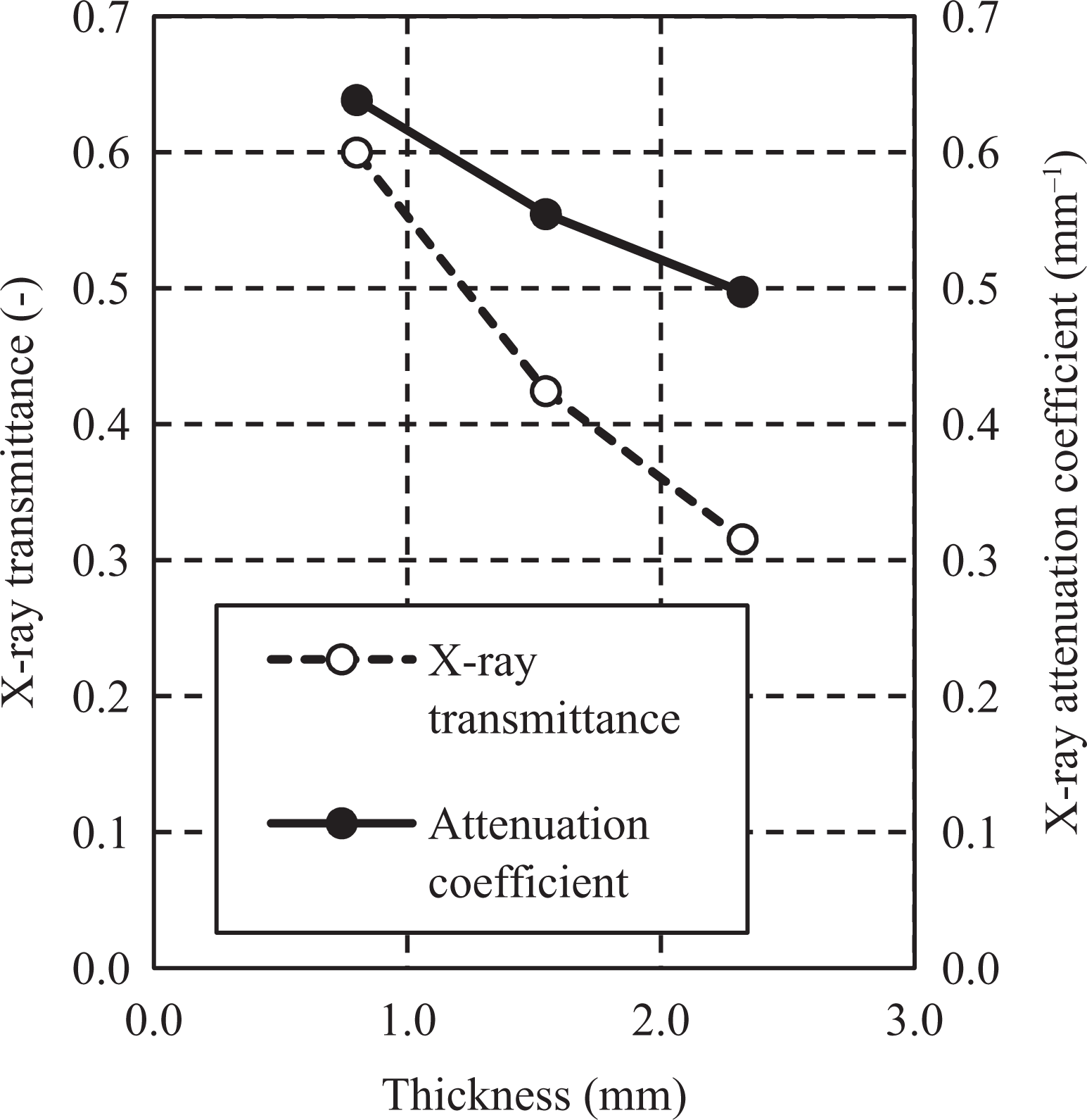
Relationship between the X-ray transmittance, attenuation coefficient, and thickness of the composite made of CF/PP prepreg.
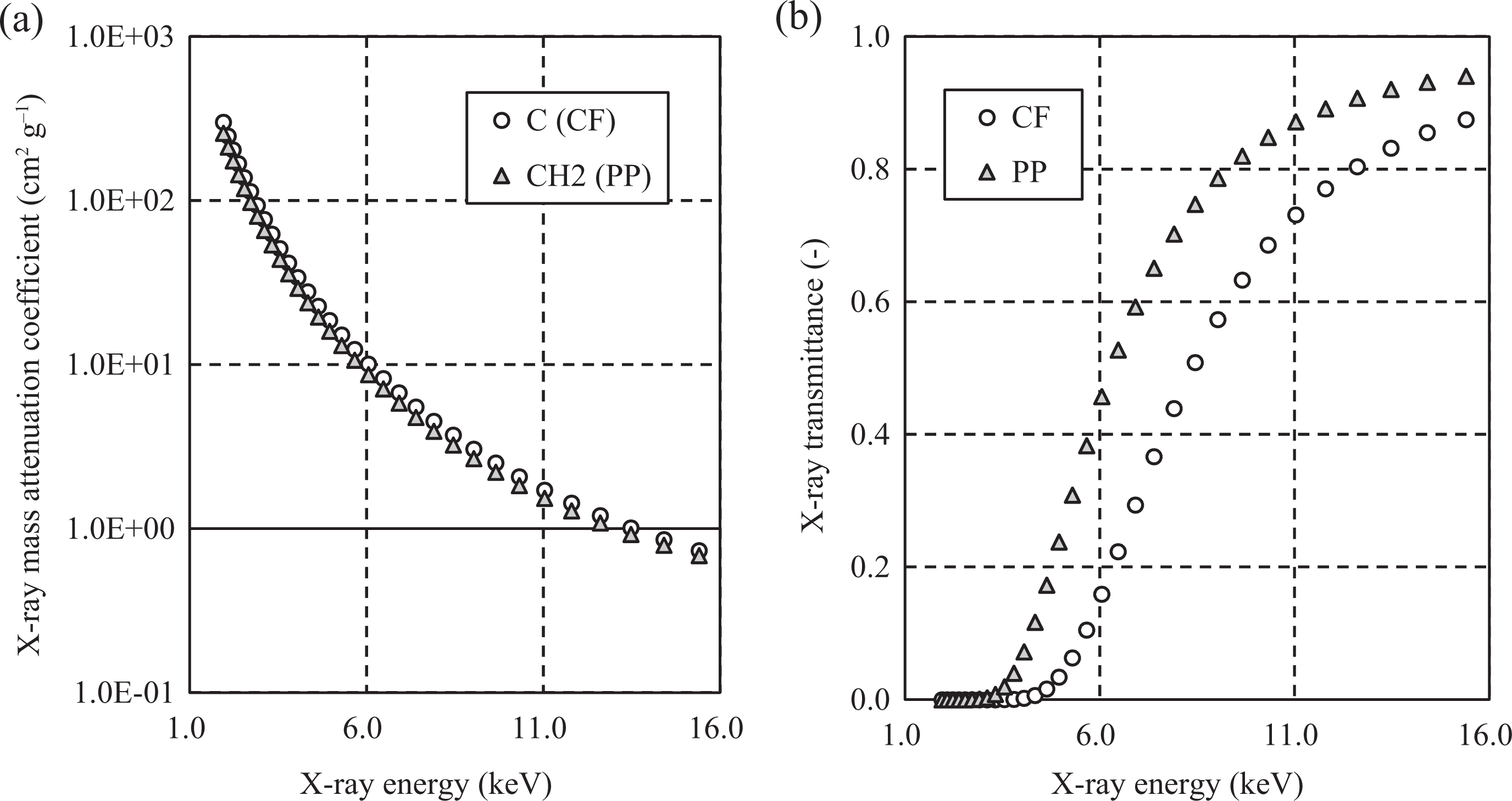
Relationship between the X-ray mass attenuation coefficient (a) and X-ray transmittance (b) and energy of 1 mm CF and PP.
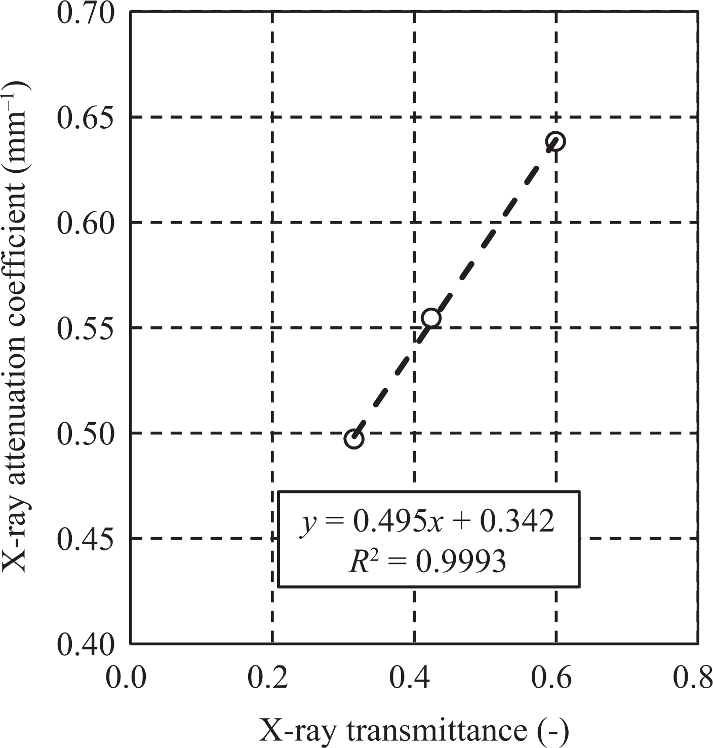
Relationship between X-ray attenuation coefficient and transmittance of composite made of CF/PP prepreg.

where m is the mass attenuation coefficient, t is the thickness, and ρ is the density.
Figure 6(b) indicates lower energy X-rays have lower transmission for both of these materials. Thus, lower energy X-rays are easily blocked by thicker composite materials. Hence, the attenuation coefficient of total X-rays decreased with increasing thickness, different from the behavior predicted by general X-ray transmittance theory. More research and discussions will be necessary to completely elucidate the thickness dependence. We measured four PET plates with thicknesses of 1, 2, 3, and 4 mm as homogeneous materials for comparison with the composite plates; the results for the PET plates are presented in Appendix 1.
Here, we note that “thickness dependence” is an ambiguous term to apply to the quantification of void content because the thickness of a material depends on its void content. By contrast, the transmittance of materials does not depend on void content. Thus, “transmittance dependence” is a more suitable word in this study. We therefore plotted Figure 7 as the relationship between the X-ray attenuation coefficient and the transmittance. In this graph, a highly linear relationship between the X-ray attenuation coefficient and the transmittance are observed in the case of CF/PP composites. Furthermore, other linear relationships between the X-ray attenuation coefficient and the transmittance are observed using PET plates and two other soft X-ray tubes are presented in Appendix 1. In the next section, we will discuss the measurements of the void content in composite materials under the assumption of a linear relationship between the X-ray attenuation coefficient and the transmittance.
Results of void content in a CF/PP semi-preg composite by hydrostatic weighing
The weight fraction of carbon fibers in the CF/PP semi-preg was 61.8%, as determined by burning tests. Figure 8 presents the void content in cross-ply composites made of semi-preg, as determined by the hydrostatic weighing method in conjunction with equation (1). The error bars in this graph represent the standard deviation for each sample. The void contents were greater than 4% in the cross-ply composites prepared under condition set A; in particular, that of the 8-ply composite was greater than 6% because consolidation for a thin plate less than 1 mm is too difficult to compensate for each rough layer. By contrast, the void contents of the composites consolidated under condition set B were less than 3.5%.
Void content of cross-ply composites of semi-preg, as determined by the hydrostatic weighing method.
Figures 9(a) to (f) show digital microscopic images of cross sections of six composite plates of semi-preg. Numerous voids were observed in all of the composite plates. The void content can be calculated from these images using image analysis; however, the obtained values would represent the void content only in the observed local area. Hence, a quantitative comparison of a whole specimen with an observed local part is difficult.
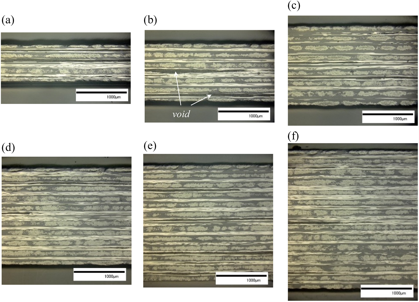
Cross sections of laminated composite of 8-ply (a), 12-ply (b), 16-ply (c), 20-ply (d), 24-ply (e), and 28-ply (f) semi-preg.
X-ray transmittance and attenuation coefficients of composites of CF/PP semi-preg
Figure 10 shows the relationship between the X-ray transmittance and apparent average thickness of each specimen of six composites of CF/PP semi-preg. Furthermore, the relationship between the apparent X-ray attenuation coefficient and X-ray transmittance of each specimen is shown in Figure 11. As mentioned above, the apparent X-ray attenuation coefficient depends on void content, is not applicable among composite panels with different void content. The apparent X-ray attenuation coefficient should be modified with void content in the composite measured by an appropriate method such as hydrostatic weighing. Figure 12 shows the relationship between true X-ray attenuation coefficient and X-ray transmittance modified by equation (7) with apparent average thickness and void content measured by hydrostatic weighing of each specimen. This graph shows a highly linear relationship between two X-ray values of semi-preg. This approximation line was almost the same as the equation shown in Figure 7, calculated by composites without voids by autoclave, which indicated X-ray attenuation coefficient does not depend on laminate pattern and semi-impregnated materials are not required to impregnate perfectly using autoclave to obtain the approximation line of impregnated material. Moreover, the true X-ray attenuation coefficient of not-prepared composites can be calculated such as 9, 11, and 13 plies by the measurement of X-ray transmittance and already known approximation line of CF/PP material.
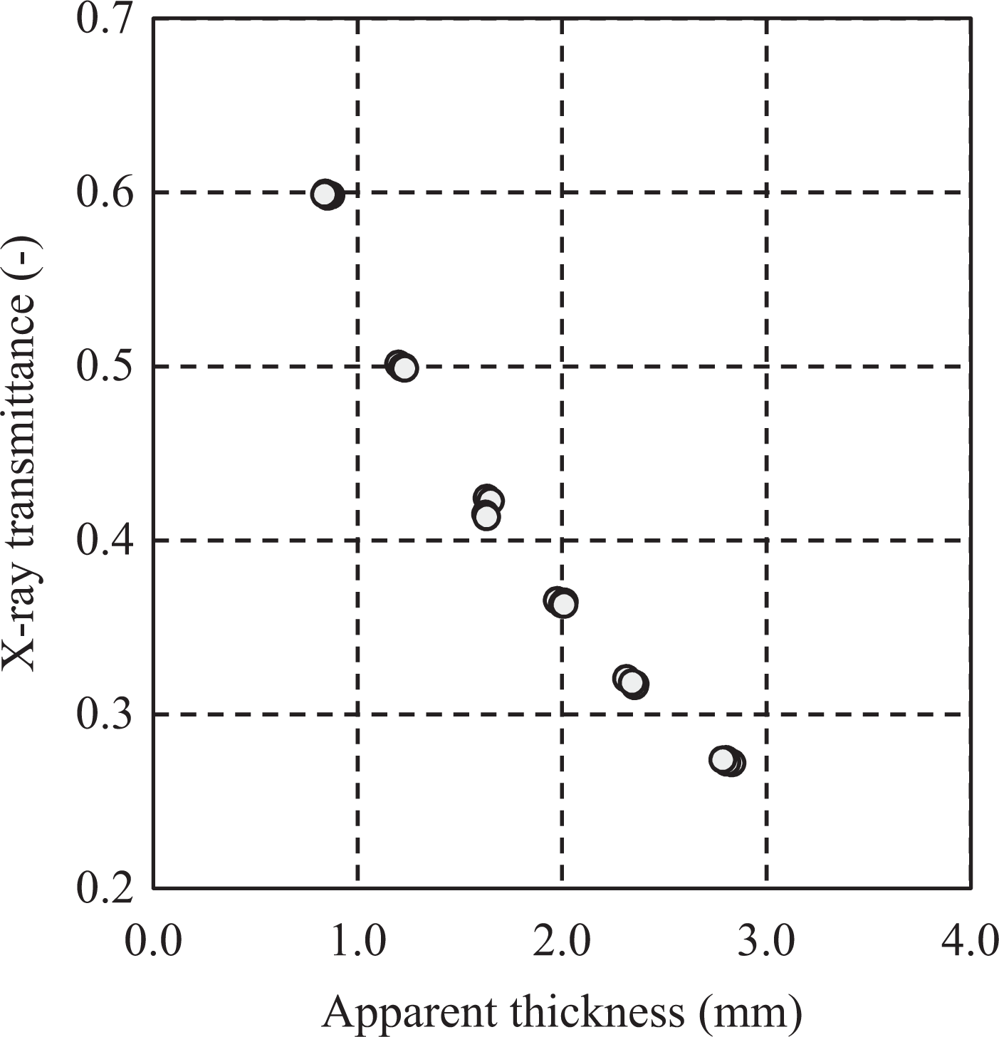
Relationship between the X-ray transmittance and the apparent thickness of CF/PP plates of semi-preg.
Relationship between the apparent X-ray attenuation coefficient and the X-ray transmittance of CF/PP plates of semi-preg.
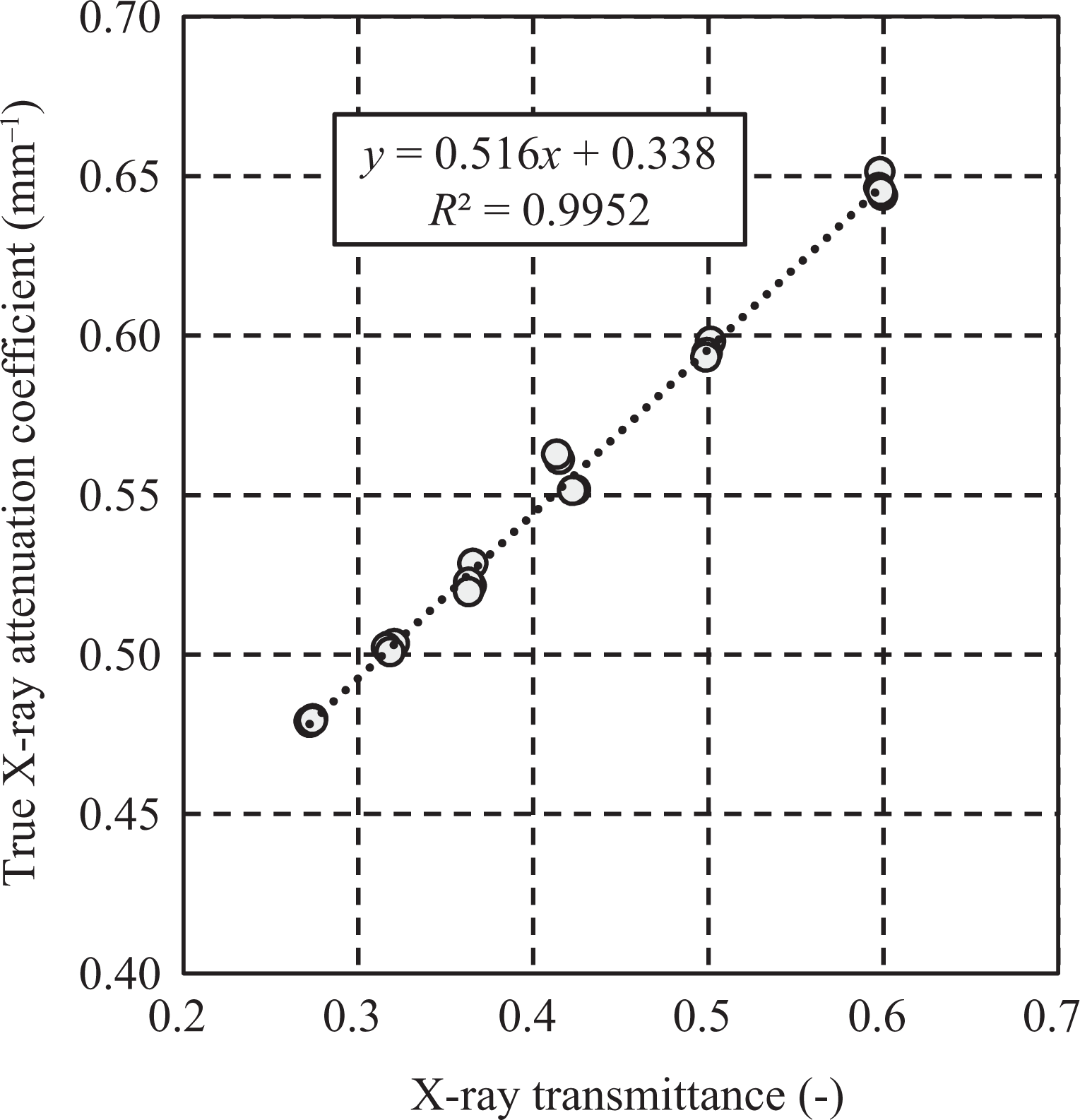
Relationship between the true X-ray attenuation coefficient and the X-ray transmittance of CF/PP plates of semi-preg.
Comparison of void content by hydrostatic weighing and by X-ray transmittance
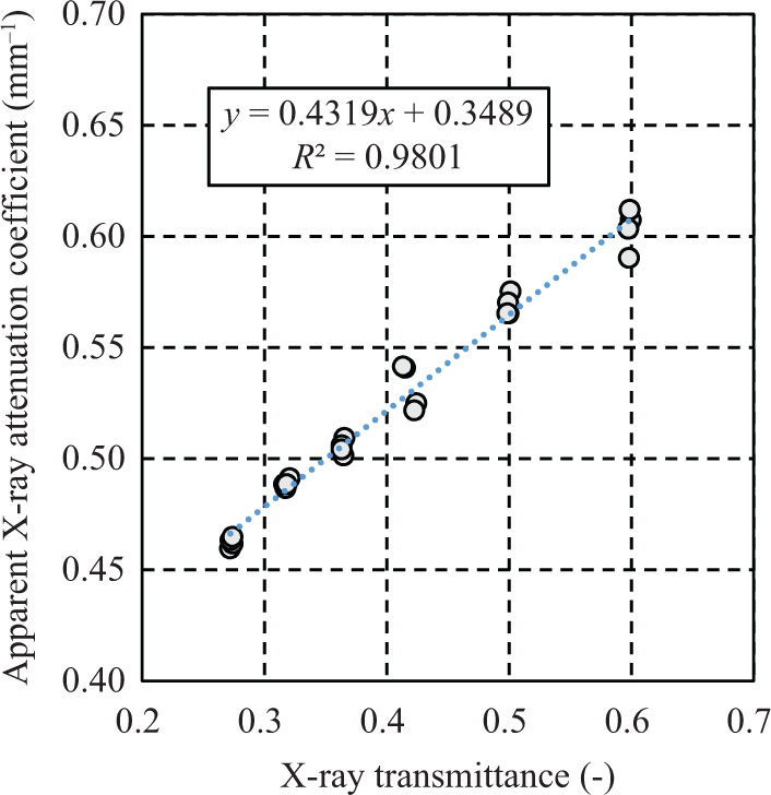
The void contents measured by the X-ray transmittance method and the conventional hydrostatic weighing method were compared. The void contents in three cross-ply plates of 12-, 20-, and 28-ply semi-pregs were measured by true X-ray approximation lines calculated from the residual three composites of 8-, 16-, and 24-ply semi-pregs. Figure 13 shows the relationship of the true X-ray attenuation coefficient and the X-ray transmittance of three composite plates of 8-, 16-, and 24-ply semi-pregs. Equation (10) is plotted as the approximation line in Figure 13.
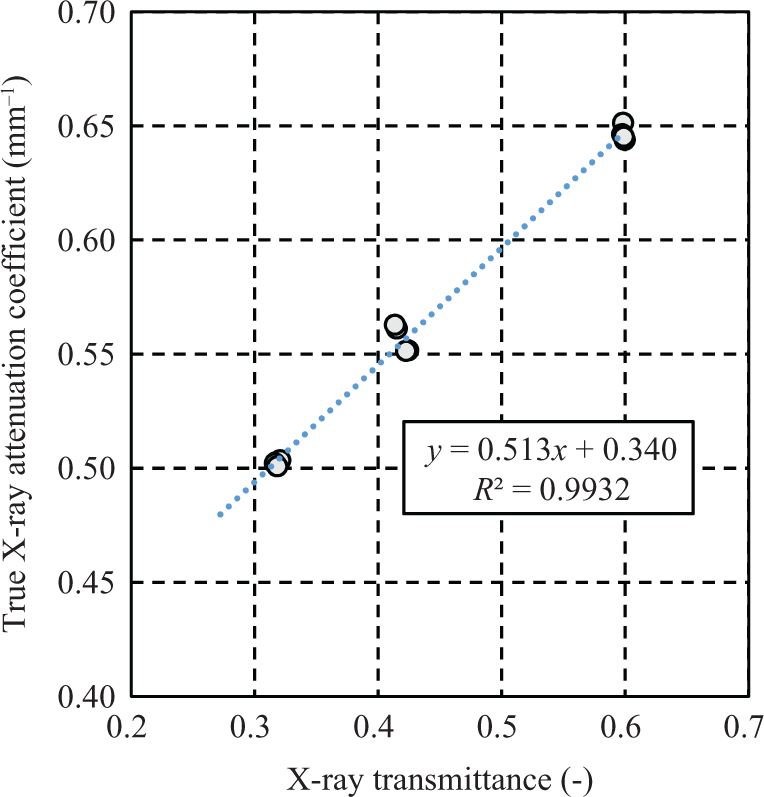
Relationship between the true X-ray attenuation coefficient and the X-ray transmittance of laminated CF/PP plates of 8-, 16-, and 24-ply semi-pregs. Equation (10) is plotted as the approximation line.

The true X-ray attenuation coefficients of the other three composite plates with 12-, 20-, and 28-ply semi-pregs were calculated on the basis of equation (10) by measuring the X-ray transmittance of each plate. The void content was calculated according to equation (11), which is derived from equation (7).
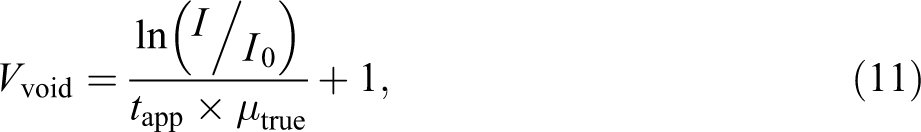
Figure 14 shows a comparison of the void contents in the three composites measured by hydrostatic weighing and by X-ray transmittance for each specimen. This comparison reveals that the difference of void content between two methods was less than 1.25% in the cases of the three composite plates. The average difference of void content of 12 specimens was 0.43%. When true attenuation coefficients were calculated by the equation of fully impregnated plates in Figure 7, the average and maximum difference of void content of 12 specimens was 0.60% and 1.31%, respectively. The difference between the two coefficients was too small. This result indicates that this method is applicable for analysis of the void content of composite plates of any thickness, where the laminate pattern consists of 8–24 plies.
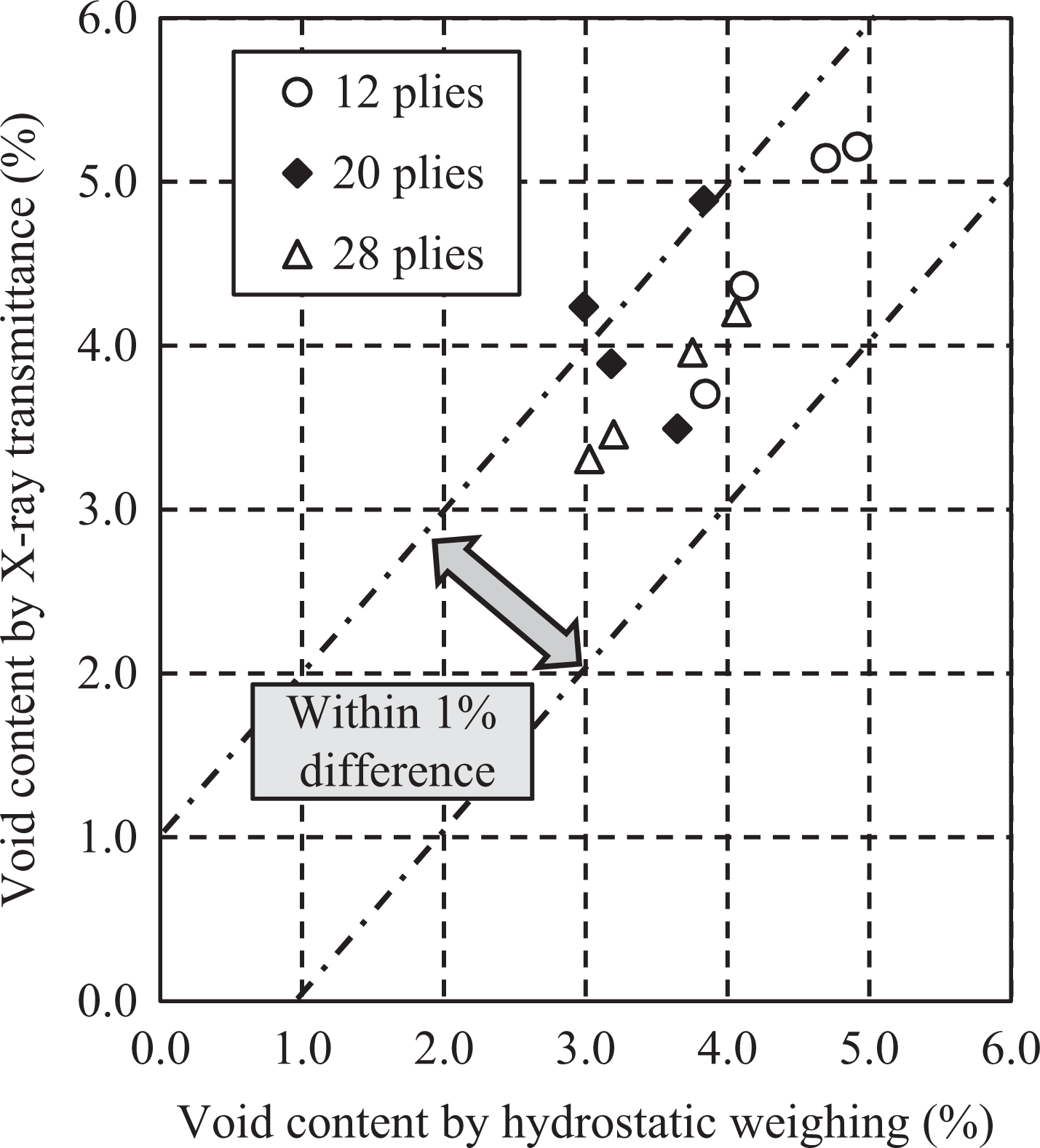
Void contents of composites of 12-, 20-, and 28-ply semi-pregs, as measured by hydrostatic weighing and by X-ray transmittance.
For the measurement of the void content of composite materials, the linear approximation line from experiments using partially impregnated composites with void-modification or fully impregnated composites should be obtained. From the NIST database, the probability of predicting the relationship between X-ray transmittance and attenuation coefficient only by the information of chemical composition of carbon fibers and matrix resin is very small. One reason is that the initial X-ray spectrum is required before transmission to materials. The other reason is that compositions of almost all resins are unknown because matrix resin includes many additives and chemical modification against their molecules.
Conclusions
We investigated a method for the nondestructive measurement of the void content in composite materials using an approximation line between soft X-ray transmittance and the attenuation coefficient. When the approximation line of the material has already been obtained, this method can be used to nondestructively approximate the void content of composites of any thickness within the range of the approximation line. The average difference in the void content determined by conventional hydrostatic weighing and that determined by the X-ray transmittance method was 0.43%; thus, this X-ray transmittance method should be acceptable for use in the continuous production of CFRP parts.
Footnotes
Appendix 1
To interpret the thickness dependence of X-ray attenuation coefficients more concretely, we measured the X-ray transmittance and calculated the attenuation coefficient of PET plates to compare the thickness dependence of CF/PP composite panels, as shown in Table 2. In addition, three different soft X-ray tubes (listed in Table 3) were used to elucidate the effects of the target material and the target voltage. X-ray energy generated from a titanium (Ti) target exhibits a sharp peak, unlike that generated from a tungsten (W) target.
Figures 15 and 16 show the X-ray transmittance and attenuation coefficients of PET plates and CF/PP plates measured using three different soft X-ray tubes. The scatter of data was small; thus, error bars were not included in these figures. In Figure 15, because the total X-ray intensity from the tube with a Ti target was less than that from tubes with W targets, the X-ray transmittance measured using the Ti target was lower than that measured using W targets. Thus, in the case of the Ti target, the X-ray transmittance of the 4-mm-thick PET plate could not be measured using our device. In addition, the X-ray transmittance from the W/9.5 kV tube was lower than that from the W/14.5 kV tube because of the lower total X-ray intensity. The X-ray transmittances of the 3 mm PET plate measured using the Ti/9.5 kV tube and the 4 mm PET plate measured using the W/9.5 kV tube were too small (approximately 0.001 (0.1%)) and contained large errors; thus, the attenuation coefficient did not decrease with increasing thickness in Figure 16. In Figure 17, linear relationships between the X-ray transmittance and the attenuation coefficient were observed in the cases of both PET and CF/PP plates using three different soft X-ray tubes.
Acknowledgements
The authors would like to express sincere appreciation to the project members who have provided valuable information and useful discussions.
Declaration of Conflicting Interests
The author(s) declared no potential conflicts of interest with respect to the research, authorship, and/or publication of this article.
Funding
The author(s) disclosed receipt of the following financial support for the research, authorship, and/or publication of this article: Part of this study was supported financially by Japanese METI project “The Future Pioneering Projects/Innovative Structural Materials Project” since 2013.