
Abstract
In the present article, a highly heat-resistant composite with a high fiber volume fraction (Vf > 60%) was successfully manufactured using engineering plastic Nylon66 as matrix and carbon fabric as reinforcement by a solution impregnation molding method. The mechanical properties of the composite were investigated using a tensile measuring device. Mechanical analysis revealed the superior mechanical properties of the composite relative to those of previously reported carbon fiber-reinforced thermoplastics (CFRTPs). The cross section and fracture surface of the composite were characterized by scanning electron microscopy. The resin successfully impregnated the fiber bundles and the bonding strength of the fiber–resin interface was excellent. Dynamic mechanical analysis was used to evaluate the heat-resistant property of the composite. The composite exhibited a better heat-resistant property relative to that of the carbon fiber-reinforced crystalline co-polyester composite. To further verify the versatility of this method, super engineering plastic polyetherimide with a higher molecular weight was successfully employed as matrix to prepare CFRTP.
Keywords
Introduction
In recent years, demands for low-weight and high-strength materials that are adaptable to high-temperature environments, such as space re-entry vehicles, supersonic aircrafts, and resistant tool jigs, have significantly increased. 1,2 Fiber-reinforced composites constitute a major breakthrough in the progress of this field. Additionally, the development of strong and stiff fibers, such as glass fibers, carbon fibers, and Aramid, along with concurrent development of the polymer industry have contributed considerably to the growth of fiber-reinforced composites. 3 Among them, carbon fiber-reinforced thermosetting plastics (CFRPs) have been used in the manufacture of airplanes fuselage owing to their important attributes such as fatigue resistance, high strength, low weight, and corrosion resistance. 4 Furthermore, owing to increasing interests in worldwide environmental issues, researchers have been committed to reducing vehicle weights. It has been shown that a total vehicle mass reduction of approximately 15% can result in a 10% decrease in the consumption of fossil fuels and consequent carbon dioxide emissions. 5 Thus, fiber-reinforced thermosetting plastic (FRPs) have maintained their staggering growth in recent years. However, because FRPs that involve thermosetting resin cannot be remelted or re-form after molding,6,7 they are typically landfilled, thereby potentially instigating serious environmental pollution. In contrast, fiber-reinforced thermoplastic (FRTP) composites possess higher recycling properties. Hence, in recent years, manufacture methods of thermoplastic prepregs that can be used to prepare FRTPs directly have been researched by many researchers. 8,9 Some factors related to manufacture and properties of thermoplastic prepregs were also explored by some researchers. 10 –12
However, the main problem associated with the application of thermoplastic matrices in composites is the difficulty in impregnating the thermoplastic matrices into fiber bundles owing to their considerable higher viscosities (500–5000 Pa·s) at melting temperatures when compared with that of thermosetting resins (commonly <100 Pa·s). Poor impregnation may lead to low fiber volume fractions (Vfs). 13,14 According to the law of mixture, the mechanical property of composites mainly depends on the Vf. 15 Thus, developing approaches to achieve efficient resin impregnation to increase Vf values are important. To this effect, various methods have been proposed in the last few years, however, the resulting Vf of some of the prepared composites remains insufficiently low. 16 –18 Some researchers explored a reformative solution impregnation molding method for molding fabric-reinforced thermoplastics and achieved a significant breakthrough. The Vf of the resulting composite was increased to over 60%, which is equivalent to that of fiber-reinforced thermosetting plastics. 19 Additionally, using the same method, we successfully prepared carbon fibers-reinforced polyester (CF/PET) composite. Likewise, the Vf of the CF/PET composite material reached up to 63.8%. However, the usage temperature of the composite was only approximately 70°C, indicating that it cannot be applied in a high-temperature environment. Therefore, developing thermoplastic materials with high heat-resistant properties, as substitutes to FRPs whose usage temperature was about 120°C, is also necessary.
Engineering plastics that possess excellent heat-resistance properties are potential candidates. However, the melt viscosity of resins is considerably higher than that of thermosetting resins and ordinary thermoplastics (such as polypropylene and PET) owing to their high molecular weight, and the latter property may still result in low Vf values if traditional molding methods are employed. 17,20
In this study, to reduce the viscosity of thermoplastics to achieve higher impregnation between the fiber bundles and matrix resin, a solution impregnation molding method was used to prepare carbon fiber-reinforced thermoplastics (CFRTPs). 19 Tensile test, three-point bending test, and thermal performance test confirmed that the manufactured composites possessed excellent mechanical properties and high heat-resistant properties. A type of super engineering plastic with a higher molecular weight was also used to manufacture composite materials to further verify the versatility of this method.
Experimental
Materials
Carbon fabric was employed as reinforcing material because of its considerably lighter, stronger, and stiffer properties over traditionally used reinforcing materials. Owing to the above advantages, carbon fabric has been widely applied in airplanes, cars, and aerospace vehicles. 21,22 The carbon fabric (Torayca® T300), which features plain weaves, used in this study was purchased from Toray Co. Ltd. (Tokyo, Japan). It has a tensile strength of 3,530 MPa and a tensile modulus of 230 GPa.
Two types of thermoplastic resins were used in this article: Nylon66 (PA66; Product Number 429171, Sigma–Aldrich Co. LLC., St. Louis, Missouri, USA; melting point 250–260°C) and polyetherimide (PEI; Product Number 700193, Sigma–Aldrich Co. LLC.; melting point approximately 280°C).
Solvents formic acid and N-methyl-2-pyrrolidone (NMP) were respectively employed for PA66 and PEI. Both solvents were obtained from Kanto Chemical (Tokyo, Japan).
Composites manufacturing
First, PA66 and PEI were dissolved in formic acid and NMP, respectively, using a hotplate magnetic stirrer (Corbing PC-420D, Taitec Co. Ltd., Saitama, Japan) at the same weight percentage (20 wt%) to reduce the viscosity of the impregnating solution to achieve higher impregnation. PA66 can easily dissolve in formic acid at room temperature, hence no heating was involved during the dissolution process. In contrast, dissolution of PEI in NMP required heating at 60°C for approximately 24 h. It is necessary to measure the viscosities of resin solution (in this article, 20 wt% PEI solution, 20 wt% PET solution, and epoxy resin were measured) as this is important as it related to impregnation of fabrics. The experiment was measured with a rotator viscometer (TV-20, Toki Sangyo Co., Ltd, Japan) under the rotational speed of 30 r min−1 at 25°C.
A hand layup impregnation method was used for pre-impregnation of the reinforcing fabric with the matrix solution to achieve an adequate solution impregnation and even distribution of the solution on the surface of carbon fabric. Then, the fabric with the resin solution was placed in a vacuum oven at a temperature above the boiling point of the solvent used for adequate evaporation of the solvent. Hence, the temperature was increased from ambient temperature to either 110°C or 220°C depending on the solvent used, and the boiling points of formic acid and NMP are 100°C and 203°C, respectively. The surface of the resulting prepreg sheets was uneven following temperature decrease to ambient temperature. Surface smoothness was conducive to subsequent preparation of the composite materials. The sheets were thermally treated using a hot-press machine (table-type test press, SA-302; Tester Sangyo Co. Ltd., Tokyo, Japan), which could also remove excess resin. The hot-press temperatures were 265°C and 290°C for PA66 and PEI, respectively, and the pressure used was 0.12 MPa.
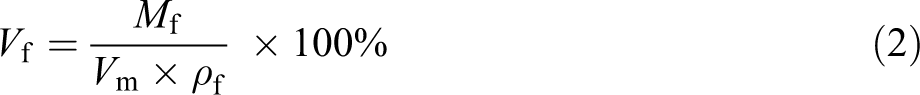
During composites manufacture, to confirm that there was no solvent residue, the weight of the carbon fabric (WCF) and the weight before and after solvent evaporation (W b and W a , respectively) were measured. The weight percentage (wt%) of evaporated solvent can be obtained according to the equation (1). Compared with the weight percentage of used solvent, whether there was residual solvent or not can be determined from the following equation:

After the temperature of the hot-press machine reached ambient temperature, the prepreg sheets were removed and cut into a certain size in accordance with the size of the metallic mold. To obtain the composites, the metallic mold was pressed at the same temperature as that used for the preparation of the prepreg sheets, however, at a different hot-press pressure and time of 3.74 MPa and 30 min, respectively. When the temperature of the metallic mold decreased to ambient temperature, the CFRTP composite was removed from the metallic mold. The method of manufacture CF/PET composite and CF/epoxy composite according to the method mentioned in A.C. Xu’s paper.
19
Just poly(p-phenylenebenzobisoxazole) fabric was replaced by carbon fabric. The CFRTPs prepared from PET, PA66, and PEI are referred as CFRTP(PET), CFRTP(PA66), and CFRTP(PEI), respectively. Similarly, he has also demonstrated that there was almost no solvent residue in prepreg sheets, indicating the solution impregnation method has no effect on the mechanical properties of the resulting composite materials. The Vf was calculated according to the mass of the carbon fabric (Mf), the volume of the prepared composite material (Vm), and the density of the carbon fibers (ρf) as follows:
Tensile test and three-point bending test
The tensile test was performed on the basis of JIS K 7054, and the size of the tensile test sample is shown in Figure 1. In this standard test, the clamp distance and drawing velocity were set at 60 mm and 1 mm min−1. Two strain gages (KFG-02-120-C1-11L1M2R; Kyowa Electronic Instruments Co. Ltd, Tokyo, Japan) were longitudinally attached at the center of both sides of each test sample to attain actual tensile modulus. At least five specimens were assessed per sample, and the average value was reported.
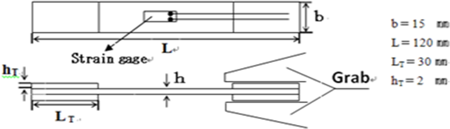
Schematic diagram of the tensile test setup.
Specimens for the three-point bending test were cut from the composites. Figure 2 shows the configuration of the specimen with planar dimensions of 100 × 15 mm2 according to JIS K 7074. The distance between the fulcrums (L) was set at 80 mm and a testing speed of 5 mm min−1 was used. Five specimens were tested per sample and the average value was reported.
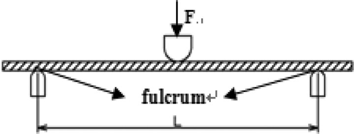
Schematic diagram of the bending test setup.
The tensile test and bending test were performed on an Autograph AG-20KND (Shimadzu Co. Ltd., Tokyo, Japan).
Scanning electron microscopy analysis
The morphology of both the polished cross-section and fracture surface (following tensile test) specimens was observed on a JSM-6010LA In Touch Scope (JEOL Co. Ltd., Tokyo, Japan) scanning electron microscope. For clear observation of the cross section, an IM4000 (Hitachi Co. Ltd., Tokyo, Japan) ion milling system was used to cut the cross section of the specimens precisely. To reduce surface charging during observation, both the polished cross sections and fractured specimens were coated with a thin layer of gold using an automatic sputter prior to observation by scanning electron microscopy (SEM). The sputter environment was argon gas.
Thermal performance test
The heat-resistance property of the composite materials was evaluated on DVA-200 (IPROS Co. Ltd., Tokyo, Japan). Rectangular specimens of 30 × 5 mm and 1–2 mm thickness were used. The initial test temperature of all the tested materials was at ambient temperature. However, the final test temperature was different depending on the melting point of the resin employed. A B-type (20 kg) dynamic sensor was used in this test because of the high strength of the carbon fiber-reinforced composites. To improve the accuracy of the experimental data, a heating rate and a test frequency of 5°C min−1 and 10 Hz were used, respectively.
Results and discussion
Tensile characteristics
Tensile strength is defined as the maximum force that a material can withstand when the material is pulled apart as well as the ability of the material to stretch prior to failure. To confirm even high-molecular-weight resins were used to prepare the composite materials, and the tensile properties of the resulting composites were similar to that of composite materials that were prepared from epoxy or low-molecular-weight thermoplastic resin.
Some parameters of composites for tensile test were shown in Table 1. The tensile properties of the composites made from epoxy, PET, PA66, and PEI are shown in Figure 3.
Composite materials’ parameters for tensile test.
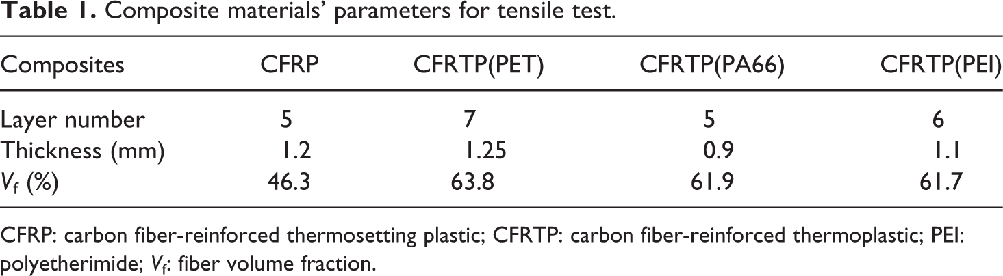
CFRP: carbon fiber-reinforced thermosetting plastic; CFRTP: carbon fiber-reinforced thermoplastic; PEI: polyetherimide; Vf: fiber volume fraction.
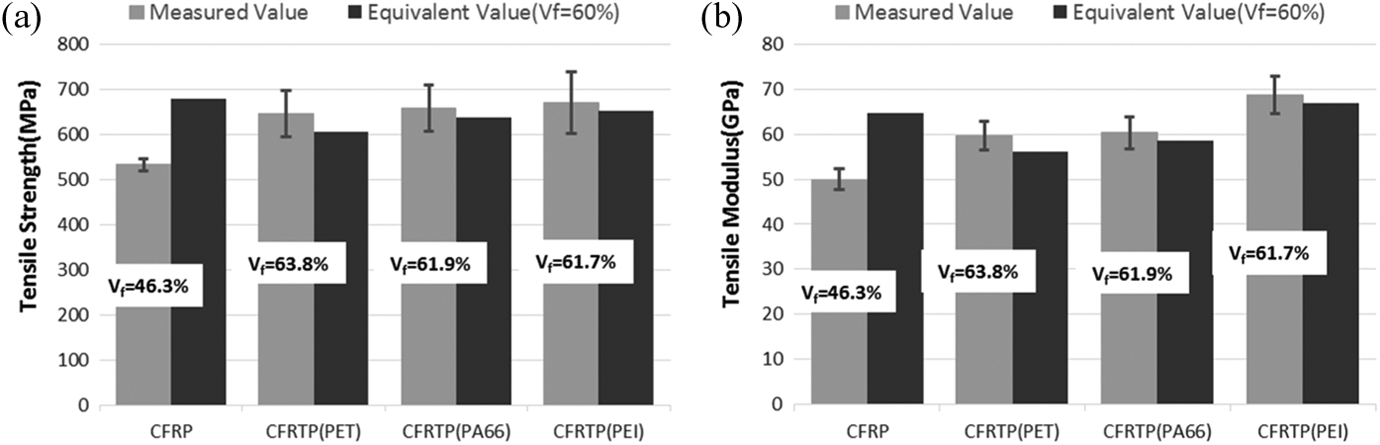
Tensile characteristics: (a) tensile strength and (b) tensile modulus of four types of composites.
As observed, we can conclude that the tensile strength of the CFRTPs prepared from PET, PA66, and PEI are similar, whereas the tensile modulus of CFRTP(PEI) is slightly higher than that of CFRTP(PET) and CFRTP(PA66). Moreover, the mechanical properties of the prepared CFRTPs appeared to be higher than that of CFRP. However, at a given Vf (60%) as shown in the Figure 3, from the values of darker columns, we can conclude that CFRP displays the best mechanical property. The interfacial adhesion between epoxy and carbon fibers is slightly stronger than that between the thermoplastic resins and carbon fibers.
Although the mechanical properties of the prepared CFRTPs were slightly lower than that of CFRP, the mechanical properties of the obtained composites are significantly better than those of previously reported composites with a Vf of only approximately 30–40%. 16 Hence, the current composites manufactured by solution impregnation method are suitable for industrial applications.
Three-point bending test
To evaluate the stiffness, the bending strength and modulus of the composite materials were evaluated using a three-point bending test in accordance to JIS K7074 procedure using a test rate of 5 mm min−1.
Some parameters of composites for three-point bending test were shown in Table 2. The experimental results are shown in Figure 4. As observed, CFRTP(PEI) possessed the best bending behavior, whereas CFRTP(PET) showed the lowest bending properties among the three types of CFRTPs tested. However, as same as tensile test, at a given Vf (60%) as shown in Figure 4, CFRP (prepared from epoxy) possessed the best bending properties among all four samples tested. The interfacial bonding between the matrix and reinforcement is an important factor to consider, which may influence the material bending behavior. Therefore, these test results also indicate that the interfacial adhesion between epoxy and carbon fibers is stronger than that between the thermoplastic resins and carbon fibers. Regardless, the currently prepared CFRTP(PEI) and CFRTP(PA66) displayed improved bending properties when compared with previously reported composites. 17 Hence herein, we demonstrate the feasibility of the solution impregnation method in the preparation of composite materials with high mechanical properties using high-molecular-weight thermoplastic resins.
Composite materials’ parameters for three-point bending test.
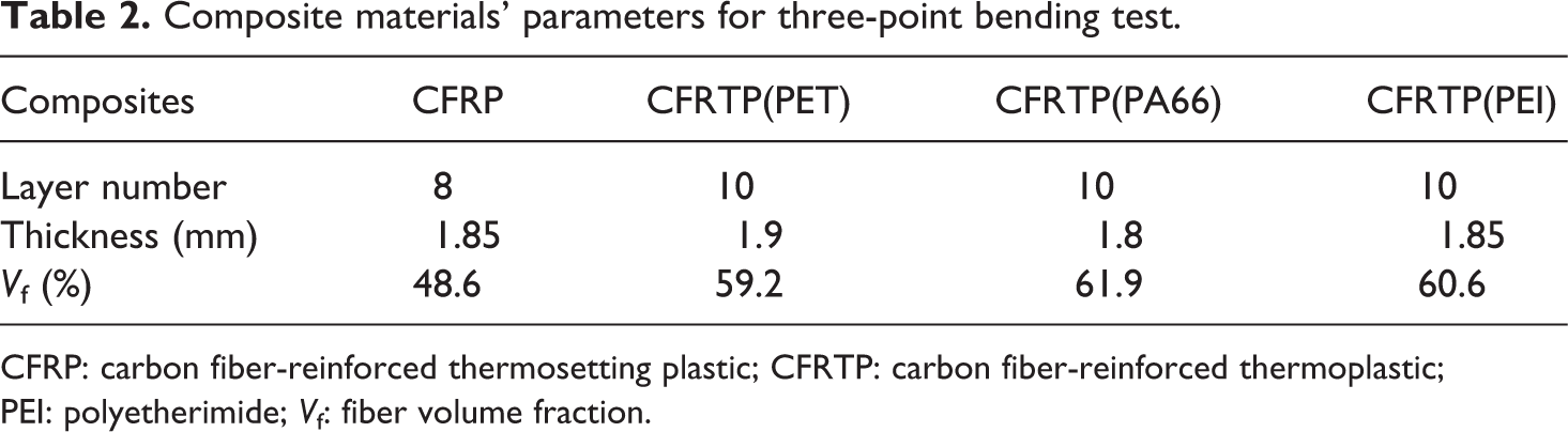
CFRP: carbon fiber-reinforced thermosetting plastic; CFRTP: carbon fiber-reinforced thermoplastic; PEI: polyetherimide; Vf: fiber volume fraction.
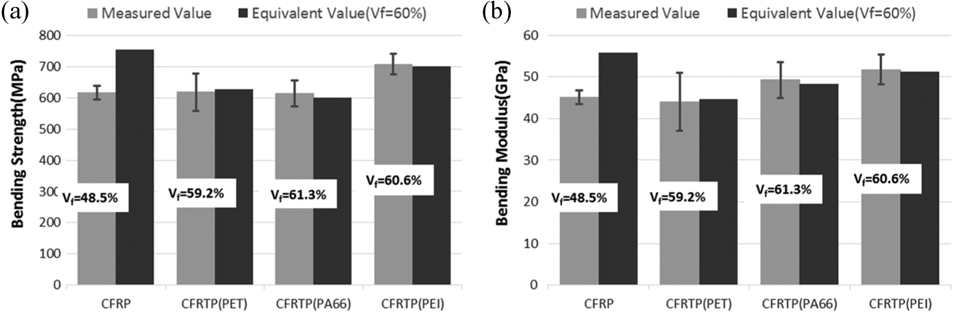
Three-point bending characteristics: (a) bending strength and (b) bending modulus of four types of composites.
Investigation of residual solvent and resin viscosities
Tables 3 and 4 show weights of different materials, according to the date of both tables, it can be confirmed that there was almost no residual solvent left in the prepreg. Because the thickness of each prepreg was just about approximately 0.1–0.2 mm, when it (with resin solution) was placed in the vacuum oven at a temperature above solvent’ boiling point, solvent can evaporate adequately. This method was also used by some researchers to remove residual solvent in samples.23,24
Calculated solvent evaporation weight percentage when formic acid weight percent is 80%.
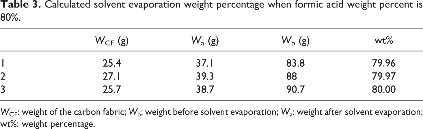
WCF: weight of the carbon fabric; Wb: weight before solvent evaporation; Wa: weight after solvent evaporation; wt%: weight percentage.
Calculated solvent evaporation weight percentage when NMP weight percent is 80%.
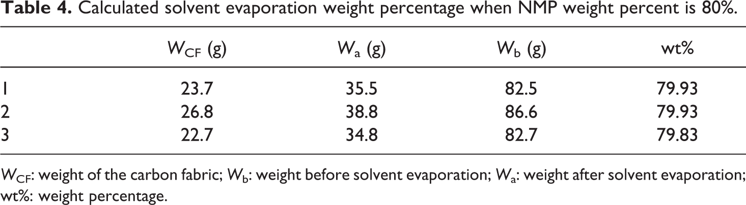
WCF: weight of the carbon fabric; Wb: weight before solvent evaporation; Wa: weight after solvent evaporation; wt%: weight percentage.
As observed by the viscosity values of matrix in Figure 5, 20 wt% PET solution had viscosities similar to that of the epoxy resin, on the other hand, although 20 wt% PEI solution seemed has much higher viscosity than epoxy resin, compared with melting viscosities of thermoplastics (approximately 500–5000 Pa·s) as referred before in this article, PEI solution possesses extreme low viscosity, which is helpful in obtaining prefect impregnation. Meanwhile, it also can verify a truth that using solvent to dissolve resin can decrease the viscosity of matrix.
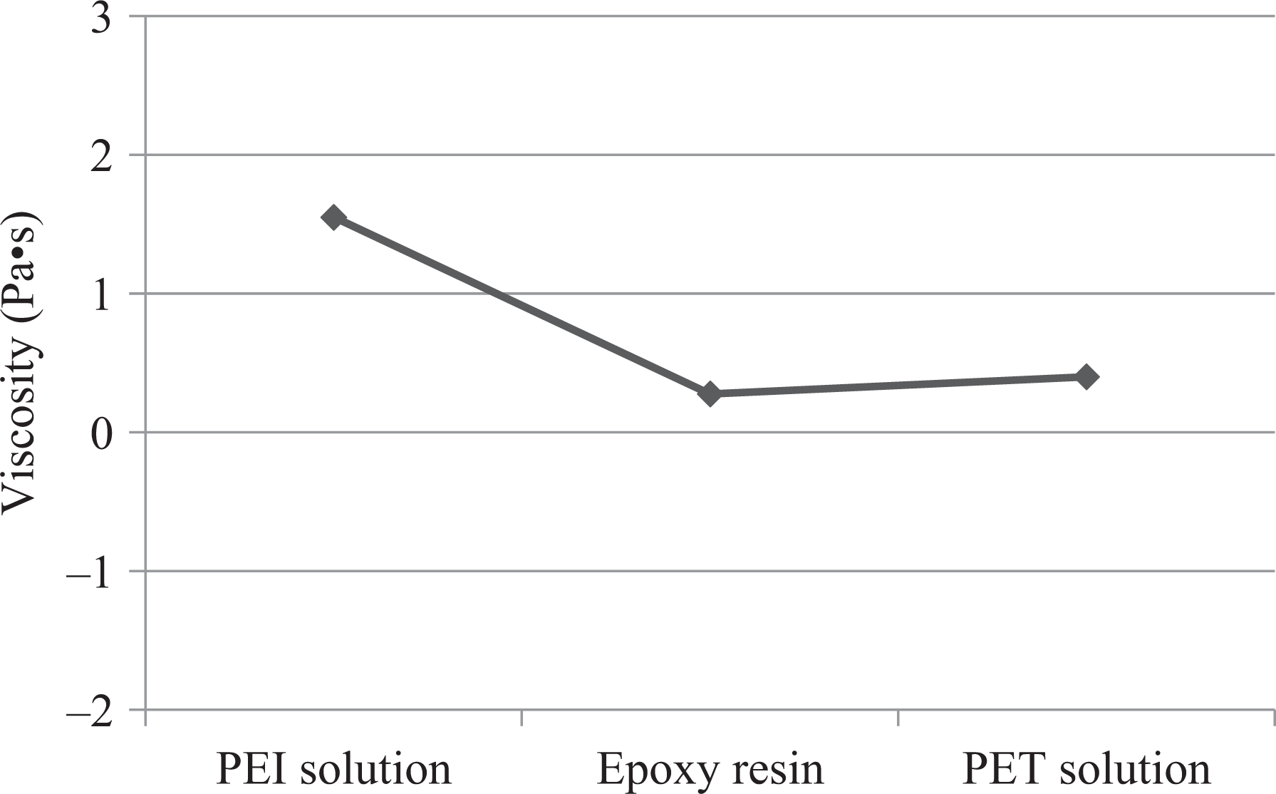
Viscosities of three different kinds of matrix.
Cross-section and fracture surface observation
The mechanical properties of composite materials are influenced by resin infusion or resin impregnation that have been investigated by some researchers. 25 Resin impregnation depends on many factors such as surface tension, capillary action, and viscosity, and the latter property is considered as the most important factor. To confirm that the solution impregnation method is effective for the complete impregnation of resin into the fiber bundles, the cross section of the resulting materials was observed by SEM, as shown in Figure 6. However, it was difficult to assess the interfacial adhesion. Hence, the specimen fractured surfaces were examined instead and shown in Figure 7.
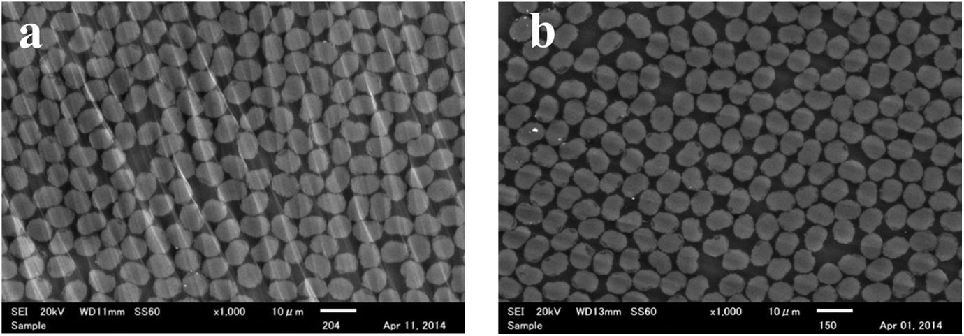
SEM images of the cross sections of (a) CFRTP(PA66) and (b) CFRTP(PEI). CFRTP: carbon fiber-reinforced thermoplastic; PEI: polyetherimide.
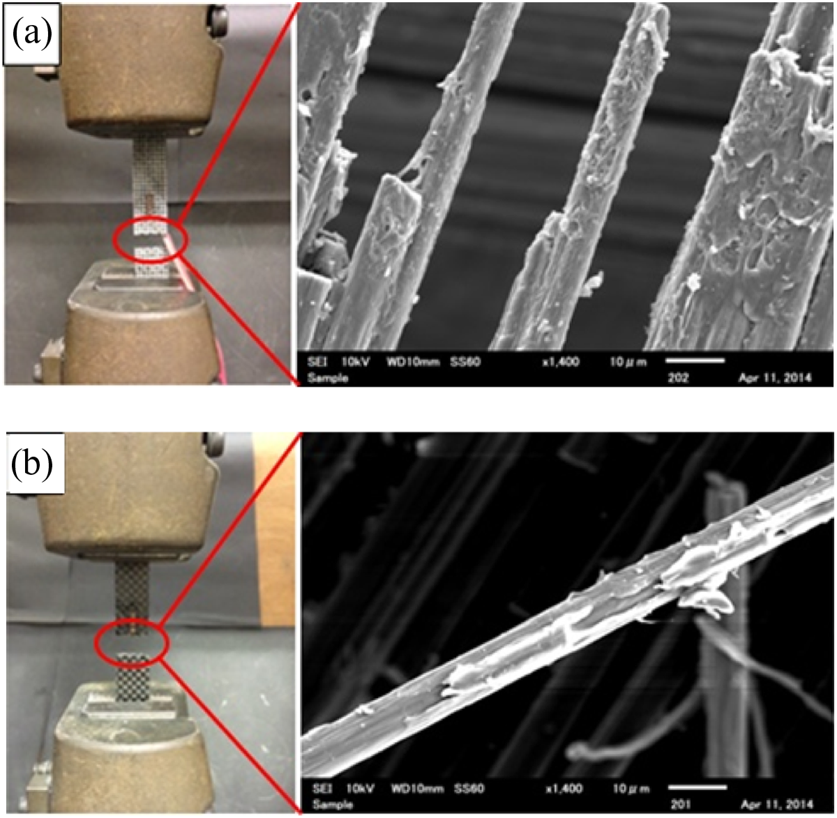
SEM images of fracture surfaces of (a) CFRTP(PA66) and (b) CFRTP(PEI). CFRTP: carbon fiber-reinforced thermoplastic; PEI: polyetherimide.
As observed in Figure 6, voids were absent in both the specimens, CFRTP(PA66) and CFRTP(PEI), indicating that the resins have impregnated the fiber bundles fully. Otherwise, if only partial impregnation occurred owing to high viscosity or other reasons, porosity would have been evident from the SEM images, as reported by Durai Prabhakaran et al. 26 Moreover, the current SEM analysis showed that the fibers arranged closely together that would explain the high Vf of the resulting composite materials.
The fracture morphology of composite materials upon breakage can be used as a measure of assessing the interfacial bonding strength of the materials. 27 To evaluate the interfacial behavior between the matrix and reinforcement, the fracture morphology of the composite materials after the tensile test was examined by SEM. The fracture appearance (Figure 7(a)) of the specimen was relatively smooth and a delamination phenomenon was absent. This suggests that failure of the material was due to brittle fracture. SEM image (Figure 7(b)) of the tensile fracture surface indicated that the fibers were well connected with the resin. Otherwise, the resin would have separated from the fibers during the tensile test; in this case, only a smooth carbon fiber surface would be apparent. In all tested materials, evidence of resin adhesion to the fibers was observed, thereby indicating excellent bonding at the fiber–resin interface.
Thermal performance analysis
Dynamic mechanical analysis was conducted to determine the storage modulus (Er) and loss modulus (Ei) of the materials as a function of temperature under an applied vibration. The relationship between the structure of the molecules and characteristics of the materials can be established. The damping factor (tan δ = Er/Ei), resulting from molecular motion in the interphase, provides information about the internal friction within the material and adhesion at the interface. 28 A significant loss in energy is observed upon increase of the damping factor. The change indicates softening of the composite materials and weakening of the adhesion at the interface between the matrix and reinforcement. The damping factor can increase up to a maximum value with variations in the temperature. In order to make it easier to compare, the temperature associated with the maximum damping (Tus) factor value was defined as equivalent maximum usage temperature, some authors defined it as maximum usage temperature directly. 29 Properties of materials will become instable if over maximum usage temperature. This temperature can be used to characterize heat-resistant properties of prepared composites.
Figure 8 shows the dynamic viscoelastic curves of the composite materials prepared from PET, PA66, and PEI, respectively. All three samples featured decreasing Er with increasing temperatures, and the storage modulus curve of CFRTP(PEI) shows a slower downward trend. This indirectly explains the excellent heat-resistance properties of CFRTP(PEI). The maximum Tus of CFRTP(PET), CFRTP(PA66), and CFRTP(PEI) are 70°C, 193°C, and 236°C, respectively. The storage modulus of all three samples declined sharply at the last heating stage of the test. This was due to the excessive softening of the resin at the high temperatures, and thus the grabs could not hold the specimens. Therefore, the heat-resistance properties of CFRTP(PA66) and CFRTP(PEI) were better than that of CFRTP(PET). Hence, in the current study, we demonstrate that composite materials prepared from high-molecular-weight thermoplastic resins using solution impregnation method are stronger than CF/epoxy composites and also possess better heat-resistance properties.
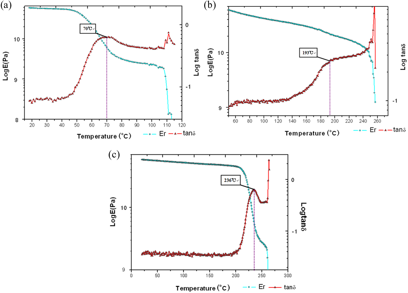
Dynamic viscoelastic curves of (a) CFRTP(PET), (b) CFRTP(PA66), and (c) CFRTP(PEI) obtained at 10 Hz. CFRP: carbon fiber-reinforced thermosetting plastic; CFRTP: carbon fiber-reinforced thermoplastic; PEI: polyetherimide.
Conclusions
CFRTPs with high heat resistance, high Vf, and excellent mechanical properties were successfully prepared from engineering plastic (PA66) and super engineering plastic (PEI) using solution impregnation molding method. The maximum usage temperatures of CFRTP(PET), CFRTP(PA66), and CFRTP(PEI) were determined using dynamic mechanical analysis. The mechanical experimental results showed that although the mechanical properties of CFRTPs were slightly poorer than that of CFRP, the currently prepared CFRTPs possessed significantly improved properties that can meet the demands of industries. SEM analysis of the composite materials’ cross sections confirmed that the resin impregnated the fiber bundles perfectly which was consequently effective in improving their mechanical properties. Based on the SEM analysis of the fracture morphologies of the composites following tensile test, we could determine that the surface of the fibers was strongly coated with the resin that could explain the high interfacial bonding strength between the matrix and fibers. All these desirable attributes strongly suggest that the CFRTPs prepared in this study are ideal substitutes to CFRPs toward meeting society needs.
Footnotes
Declaration of Conflicting Interests
The author(s) declared no potential conflicts of interest with respect to the research, authorship, and/or publication of this article.
Funding
The author(s) disclosed receipt of the following financial support for the research, authorship, and/or publication of this article: This work was supported by a grant-in-aid for Shinshu University Advanced Leading Graduate Program by the Ministry of Education, Culture, Sports, Science and Technology (MEXT), Japan.