
Abstract
Natural fiber-reinforced composite materials are finding wide acceptability in various engineering applications. A substantial increase in the volume of production of these composites necessitates high-quality cost-effective manufacturing. Drilling of holes is an important machining operation required to ascertain the assembly operations of intricate composite products. In the present experimental investigation, natural fiber (sisal and Grewia optiva fiber)-reinforced polylactic acid-based green composite laminates were developed using hot compression through film stacking method. The drilling behavior of green composite laminates was evaluated in terms of drilling forces (thrust force and torque) and drilling-induced damage. The cutting speed, feed rate, and the drill geometry were taken as the input process parameters. It was concluded that all the three input process parameters affect the drilling behavior of green composite laminates. The drill geometry was established as an important input parameter that affects the drilling forces and subsequently the drilling-induced damage.
Introduction
Application spectrum of fiber-reinforced plastics (FRPs) products has increased manifold. Due to their inherent superior properties, FRPs have captured almost every segment of application area ranging from construction, aerospace, automobile industries, and so on. 1 –3 But the use of synthetic fibers and polymers are causing serious environmental and health issues. These challenges have led to the development of green composite laminates that incorporate natural fibers in biopolymer matrix. These natural fibers have low cost, lightweight, good specific strength, good thermal insulation properties, and are renewable. 4 Natural fibers provide a viable and abundantly available substitute to expensive and nonrenewable synthetic fibers. 5,6
Automotive components are continually tasked to meet higher specifications in terms of increased vehicle efficiency, lower fuel consumption, and an improved performance at lower cost. Now, many automotive parts are being fabricated using natural fiber-reinforced composite laminates. Lightweight thermoplastic composite laminates are being used in many structural applications as well as in interior automotive components, such as trunk panels, door panels, and headliners. 7,8 Among the bio-based polymers, polylactic acid (PLA) is emerging as a sustainable polymer because of its favorable characteristics such as good mechanical properties, fully biodegradable, hydrophobic nature as well as it is derived from renewable raw materials such as corn and other agricultural waste products. Natural fiber-reinforced PLA composite laminates are replacing the synthetic polymer composite laminates in many applications, especially in exterior and interior components of automobiles. PLA-based automotive parts provide good aesthetics and are also easily processable.
A summary of an extensive review of the literature in the field of drilling of polymer composites is shown in Figure 1. The percentage contribution in terms of number of research articles (total 141) published in peer-reviewed journals is taken as reference data. Figure 1(a) shows that 91% of total research publications incorporated thermoset polymers and only 9% articles focused on drilling in thermoplastic-based composite laminates. Figure 1(b) shows that around 93% publications had considered synthetic fiber-based polymer composite laminates for drilling. But considerably lower contribution is available on drilling of natural fiber (7%)-based composites. The present summary of research publications also reveals that investigations on drilling of biopolymer-based natural fiber composite laminates have not been carried out exhaustively.
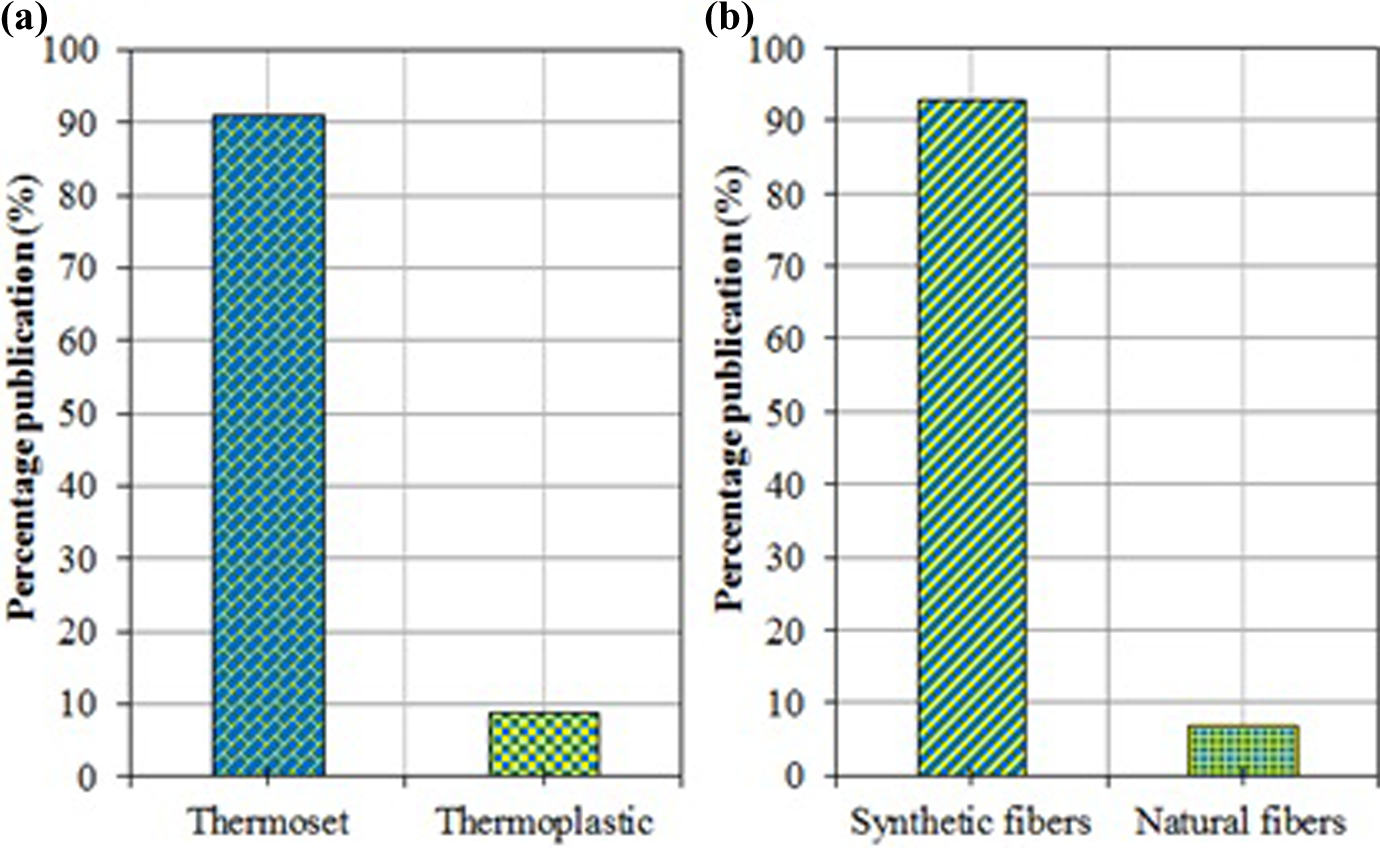
Summary of research publications.
From the literature, it is quite clear that comparatively less work is available on drilling behavior of thermoplastic-based composite laminates. 9 –13 Kim et al. 9 studied the machinability in terms of drilling forces and hole quality of the graphite/polyether ether ketone and graphite/PIXA thermoplastic composites processed through induction heat-pressed and autoclave processing. Mohan et al. 10 carried out a study on damage-free drilling of glass/polyester composite laminates with different drill size, feed rate, and cutting speed using a computer numerical controller milling center. Hocheng and Puw 11–12 compared the drilling behavior of carbon/acrylonitrile butadiene styrene and carbon/epoxy composite laminates. Franke 13 studied the influence of cutting parameters, fiber content, and cutting edge on the machining results and developed a phenomenological model describing the influence of cutting edge on drilled hole surface quality. The process variables of drilling operation depend on the type and properties of reinforcing material and polymer matrix. Therefore, the results established for synthetic FRP laminates cannot directly be used for natural fiber-reinforced composites. It has already been established that synthetic fiber such as glass and carbon fiber-reinforced composite laminates can be machined easily with standard tools whereas Kevlar fiber (an organic fiber)-reinforced composite laminates pose a number of problems owing to the higher toughness and flexibility of the fibers. 14
As natural fiber-reinforced composites are replacing synthetic fiber-reinforced composites due to increased environmental awareness, therefore, it becomes imperative to investigate the drilling behavior of green composite laminates in order to minimize the drilling-induced damage. A lot of research work is available on development and characterization of green composite laminates. 15 –19 But only a handful studies are available on drilling behavior of natural fiber-reinforced polymer composite laminates. 20 –30 Therefore, the objective of the present research endeavor is to experimentally investigate the effect of different process parameters (cutting speed, feed rate, and drill geometry) on drilling behavior of natural fiber-reinforced PLA composite laminates.
Materials and methods
Raw materials
Sisal fiber mat was obtained from Women’s Development Organisation, Dehradun, Uttarakhand, India. Grewia optiva fiber mats were obtained from Uttarakhand Bamboo and Fiber Development Board, Dehradun, Uttarakhand, India. Sisal fibers are obtained from the leaves of the sisal plant (Agave sisalana). These fibers are coarse, strong, and have good flexibility. The fibers are separated by retting method, washed in the normal water, and then dried in the sunlight. PLA was supplied by Cargill Dow (Minnetonka, Minnesota, USA) in pellets form. PLA is a fully biodegradable thermoplastic biopolymer, which is derived from lactic acid through fermentation of agricultural products like corn, potato skin, and so on. After composting, PLA-based products fully biodegrade into the atmosphere in due course of time. The biopolymer has a density of 1.24 g/cm3. The glass transition temperature (T g) and melting temperature of PLA are 58 and 180°C, respectively.
Fabrication of composite laminates
Sisal fiber-reinforced PLA (PLA/S) and G. optiva fiber-reinforced PLA (PLA/G) composite laminates were produced using compression molding through film stacking procedure. Initially, fiber mats and polymer pellets were dried in an oven to ensure that all absorbed moisture was removed. PLA pellets were converted into PLA films by compression molding machine at a temperature of 180°C under pressure. The films were then allowed to cool under pressure, and finally, films were removed. For each type of composite laminate, fiber mat and polymer films were stacked alternatively in a metallic mold. At top and bottom, thin Teflon sheets were used to avoid sticking of polymer layers to the mold plates. The whole assembly was hot pressed at a temperature of 180°C at high pressure and then the composite laminate was cooled under pressure. Composite laminates were removed from the mold after cooling. The thickness of the prepared composite was 5 mm. The specimens were cut to a size of 100 × 50 × 5 mm3 and stored in a desiccator till further use to avoid moisture absorption. The mechanical characterization of the developed composites has already been performed and the results have been published. 31
Drilling test setup and measurement
Drilling of green composite laminates was carried out on radial drilling machine (Batliboi Company Pvt Ltd, Surat, Gujarat, India), powered by 1.5 kW main spindle motor. Three different types of drill geometries, namely, twist, Jo, and parabolic drill geometry were used in the experimentation. All the drill bits were of solid carbide material having a constant diameter of 8 mm. The thrust force and torque were measured with a four-component piezoelectric drill dynamometer (type 9272A, Make Kistler, Winterthur, Switzerland) coupled with a charge amplifier (type 5070A, Make Kistler, Winterthur, Switzerland). For each type of drill geometry, drilling of the composite laminates was carried out for three different levels of cutting speeds (900, 1800, and 2800 r/min) and feed rates (0.05, 0.12, and 0.19 mm/r). As shown in Figure 2, composite laminate was mounted in a fixture located on the top of the dynamometer. The thrust force and torque signals were recorded during drilling operation by the dynamometer. The signals were processed and recorded in a computer with the help of a data acquisition software (DynoWare, Type 2825A-02, Version 2.4.1.6). A digital image processing technique was used to quantify the damage zone around the drilled holes. Images of holes were recorded with the help of digital camera (Sony DSC-S5000, Tokyo, Japan). These digital images were processed with image analysis public domain software (ImageJ Version 1.42) and damage area was subsequently calculated.
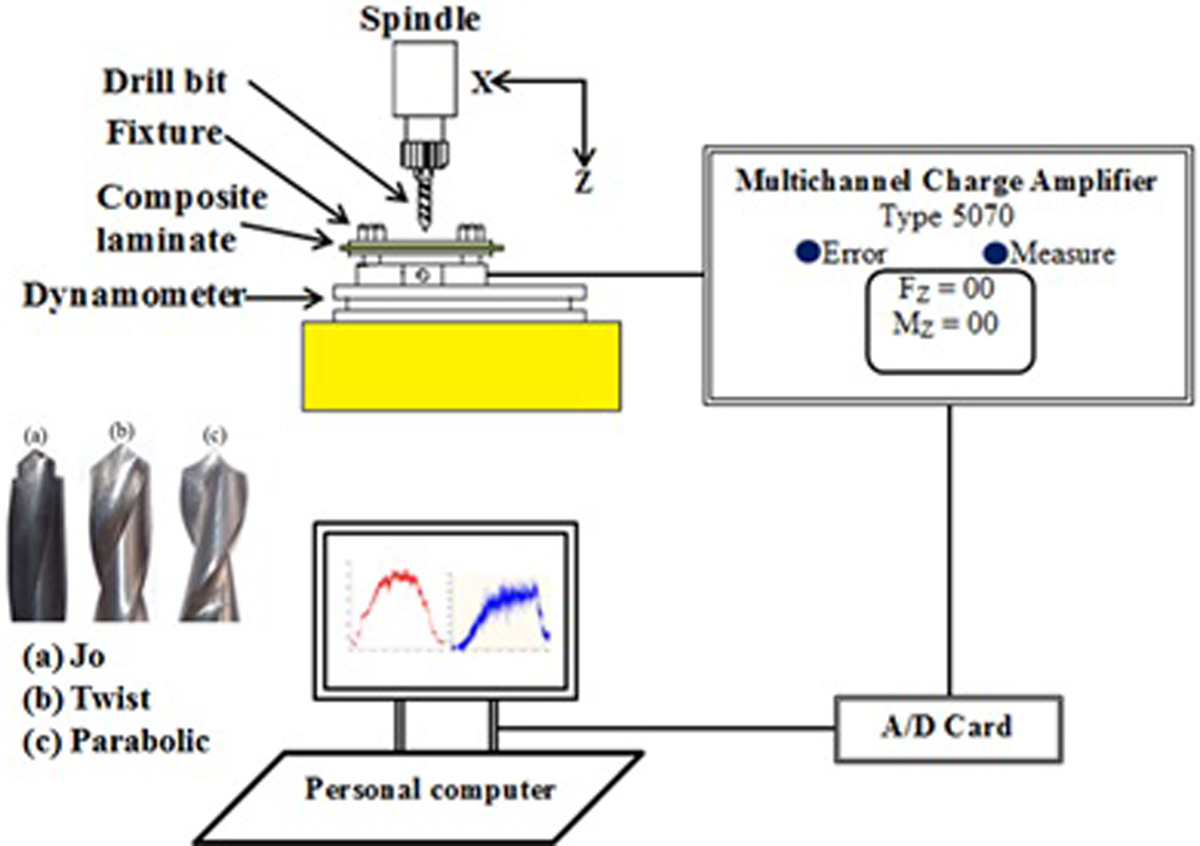
Schematic of the experimental setup.
Results and discussion
Thrust force and torque signal analysis
During drilling operation, thrust force and torque signals were recorded at various combinations of cutting speed and feed rate for different drill geometries. Typical thrust force and torque response as a function of drilling time are shown in Figure 3. Different stages of the complete drilling cycle have also been shown, corelating the stages with the recorded signals. A common trend has been observed from the thrust force and torque signals for all three drill geometries. Initially, there is an increase (zone AB) in thrust force and torque value till the complete engagement of the cutting lips with the composite laminate takes place. Then almost a zone of constant thrust and torque level is observed which is known as the complete engagement zone (zone BC). After that, signals decrease rapidly toward the end (zone CD), as the drill exits the laminate after generating a hole (zone DE). There is an abrupt variation in the signals recorded with Jo drill, which is attributed to the stepped shoulder of Jo drill geometry. Due to similarity in geometrical construction of the parabolic and the twist drill, the thrust force and the torque signals show similar graphical characteristics qualitatively but with different magnitudes.
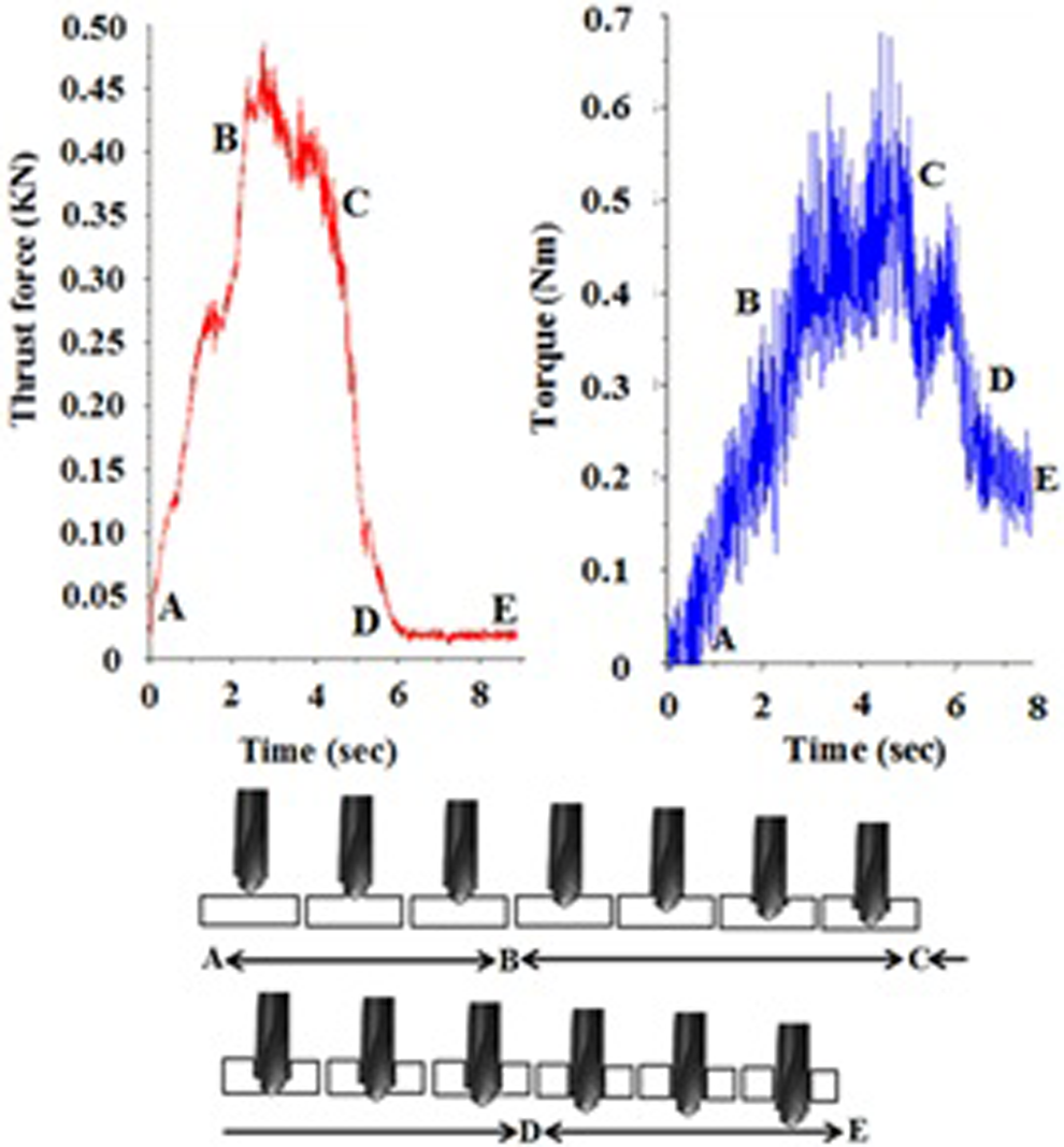
Thrust force and torque response during drilling with Jo drill for cutting speed of 900 r/min and feed rate of 0.12 mm/r.
Influence of process parameters on drilling forces
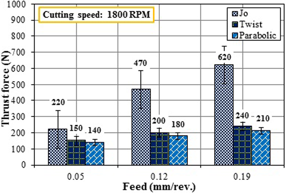
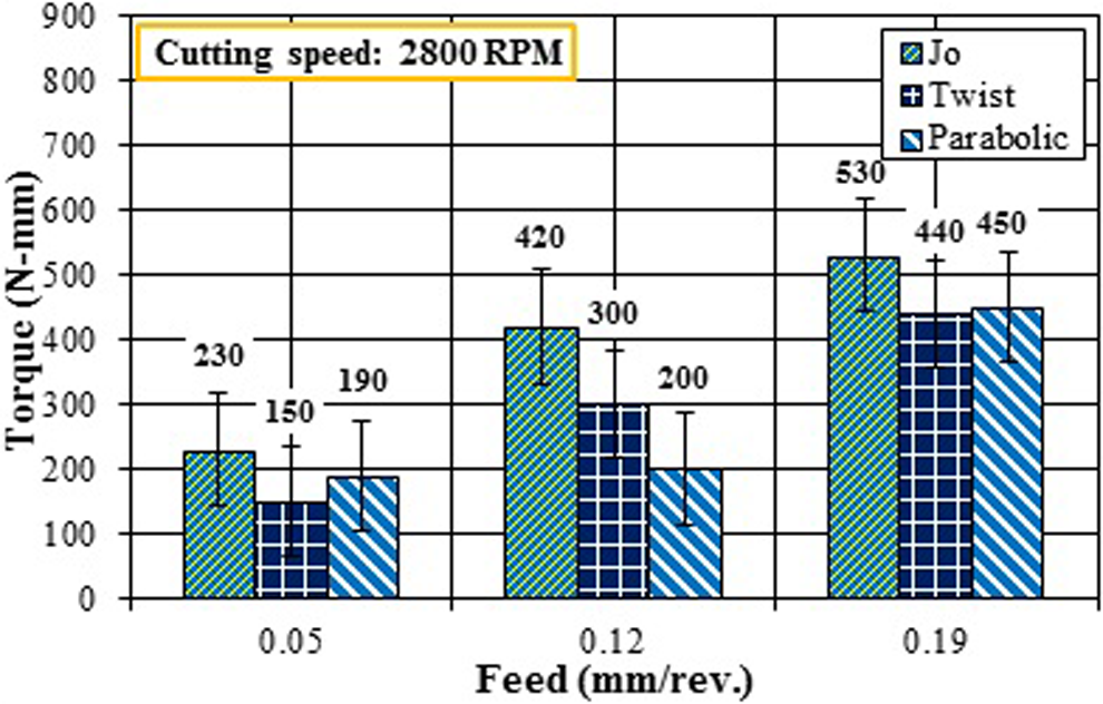
Average thrust force and torque were calculated from the full engagement zone (zone BC) of the drilling force signals. The effect of cutting speed and feed rate on the thrust force and torque has been plotted in Figures 4 to 7. Observing the thrust force response, it can be seen from the graphs that the thrust force decreases with increase in cutting speed and increases with increase in feed rate. At all the cutting speeds and feed rates, maximum thrust force was recorded with Jo drill that was having substantially different geometry. Kumar et al. 32 also reported that the thrust force generated with Jo drill is substantially high as compared to the eight-facet drill during drilling of glass/vinyl ester composites filled with silicon carbide and graphite powder. The thrust force values for twist and parabolic drill were very close to each other with twist drill showing slightly higher values. Similar characteristics of the results with the twist and parabolic drills are due to similarity in basic design of drill point with little variation in geometry. Torque response also shows the similar pattern as was observed for the thrust force. Torque decreases with increase in cutting speed and increases with increase in feed rate. Jo drill was again found to generate maximum torque during drilling operation among the three drill geometries used. The thrust force and torque analysis show that parabolic drill has been found to record minimum thrust force whereas twist drill has led to minimum torque with marginal difference in values as compared to parabolic drill. The cutting action is more predominant than the piercing while drilling is performed with parabolic drill that results in minimum value of drilling forces. Similar trend has been observed for thrust force and torque at various combinations of drilling parameters for PLA/G and PLA/S composite laminates with different magnitudes. Higher values of thrust force were recorded for PLA/G composite laminates as compared to PLA/S composite laminates. A random variation was observed in torque values for both types of composite laminates. Lower thrust force associated with PLA/S composite laminate may be attributed to the fact that sisal fibers are more brittle and rough as compared to G. optiva fibers and cutting becomes relatively easy due to the brittle nature of sisal fibers. Therefore, it can be said that the drilling behavior also depends upon the type and nature of constituents of the composite laminates. There were also random variations in thrust force and torque values at few combinations of cutting speed and feed rate. These variations may be attributed to the presence of defects (porosity, displacement of fiber layer, resin-rich area, etc.) developed during processing of composite laminates. 33 The processing method has a critical influence on drilling behavior of thermoplastic composite laminates. 9
Thrust force variation with cutting speed for PLA/G composite. PLA/G: Grewia optiva fiber-reinforced polylactic acid.
Thrust force variation with feed rate for PLA/S composite. PLA/S: sisal fiber-reinforced polylactic acid.
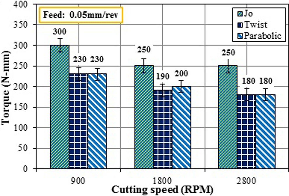
Torque variation with cutting speed for PLA/S composite. PLA/S: sisal fiber-reinforced polylactic acid.
Torque variation with feed rate for PLA/G composite. PLA/G: Grewia optiva fiber-reinforced polylactic acid.
Response surface methodology (RSM) has been used to model thrust force generated during drilling of PLA/G and PLA/S composite laminates. The regression equations have been developed to calculate thrust force for each type of drill geometry in terms of cutting speed and feed rate. Analysis of variance (ANOVA) has been used to statistically analyze the effect input process parameters individually and their interaction on thrust force. The ANOVA data are shown in Table 1. Mathematical regression equations for each type of drill geometry have been developed with the help of ANOVA, which are given in Table 2. From the ANOVA table, it is clear that the p value for thrust force model is lower than 0.05 (95% confidence) for both type of composite laminates, which indicate that both the models are significant. The significant terms are shown in the ANOVA table. The F values of lack of fit for thrust force model for PLA/S and PLA/G composite laminates are 2.59 and 2.58, respectively, which shows that lack of fit is insignificant. This indicates that the proposed models fit well. ANOVA table shows R 2 value for models of both the composite laminates. This R 2 value gives the value of determination coefficient that represents the ratio of variability explained by the model to the total variability in the actual data. R 2 values are an indication of the goodness of fit. 29 The value of determination coefficient of thrust force for PLA/S and PLA/G composite laminates are 0.9959 and 0.9828, respectively, which shows that the fit of the experimental data is satisfactory. From the ANOVA analysis given in Table 1, it is clear that feed rate, drill geometry, and their interaction are significant model terms for both PLA/S and PLA/G composite laminates. Observing the F values, it can be seen that F value for drill geometry is much higher than that of the feed rate for both the composite laminates. It implies that drill geometry has dominating influence on thrust force as compared to feed rate. Comparing the F values for both the composite laminates, it is clear that feed rate and drill geometry have stronger effect on thrust force for PLA/S composite laminates as compared to that for PLA/G composite laminates.
ANOVA for thrust force model.
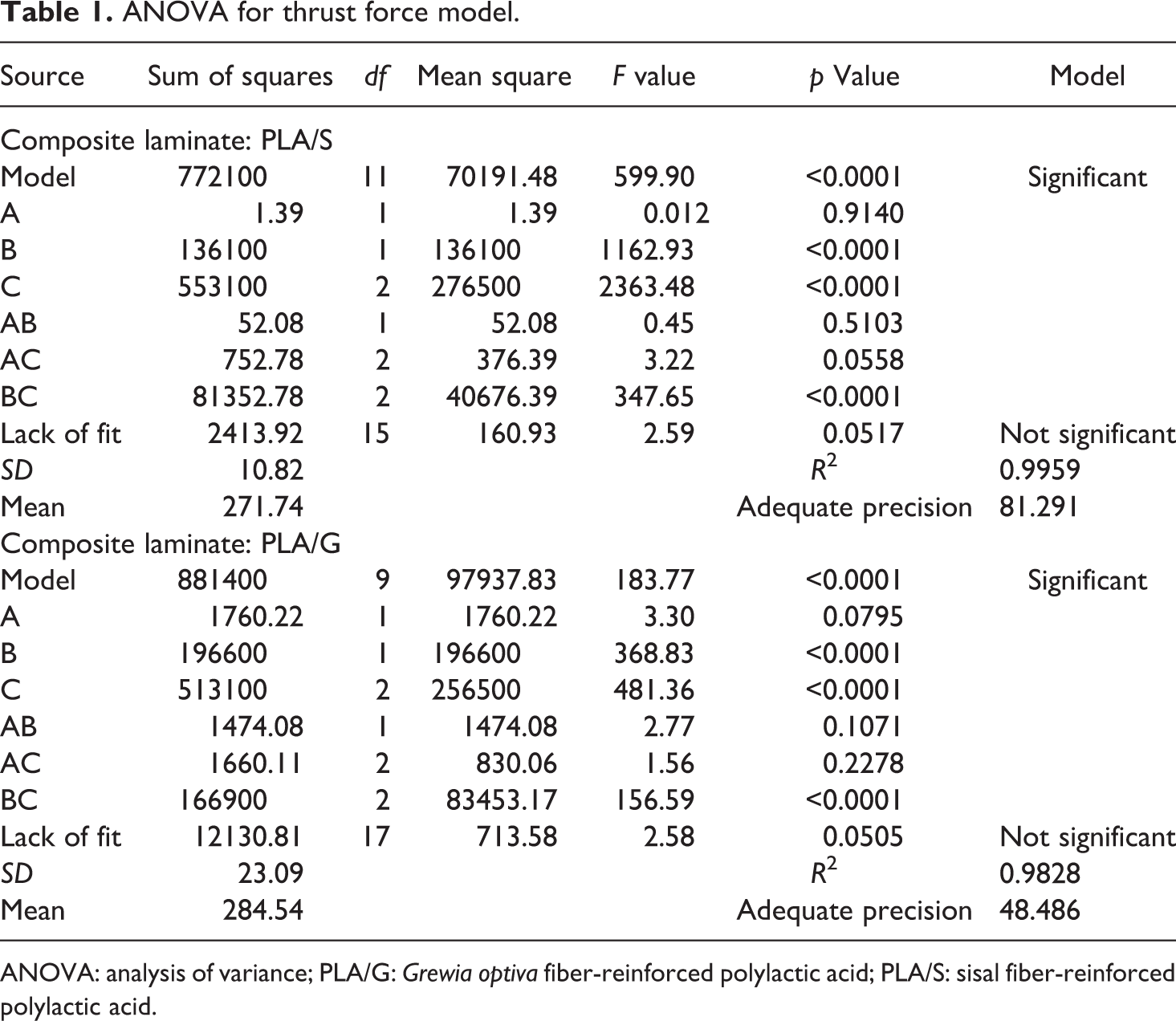
ANOVA: analysis of variance; PLA/G: Grewia optiva fiber-reinforced polylactic acid; PLA/S: sisal fiber-reinforced polylactic acid.
Mathematical models for thrust force.a
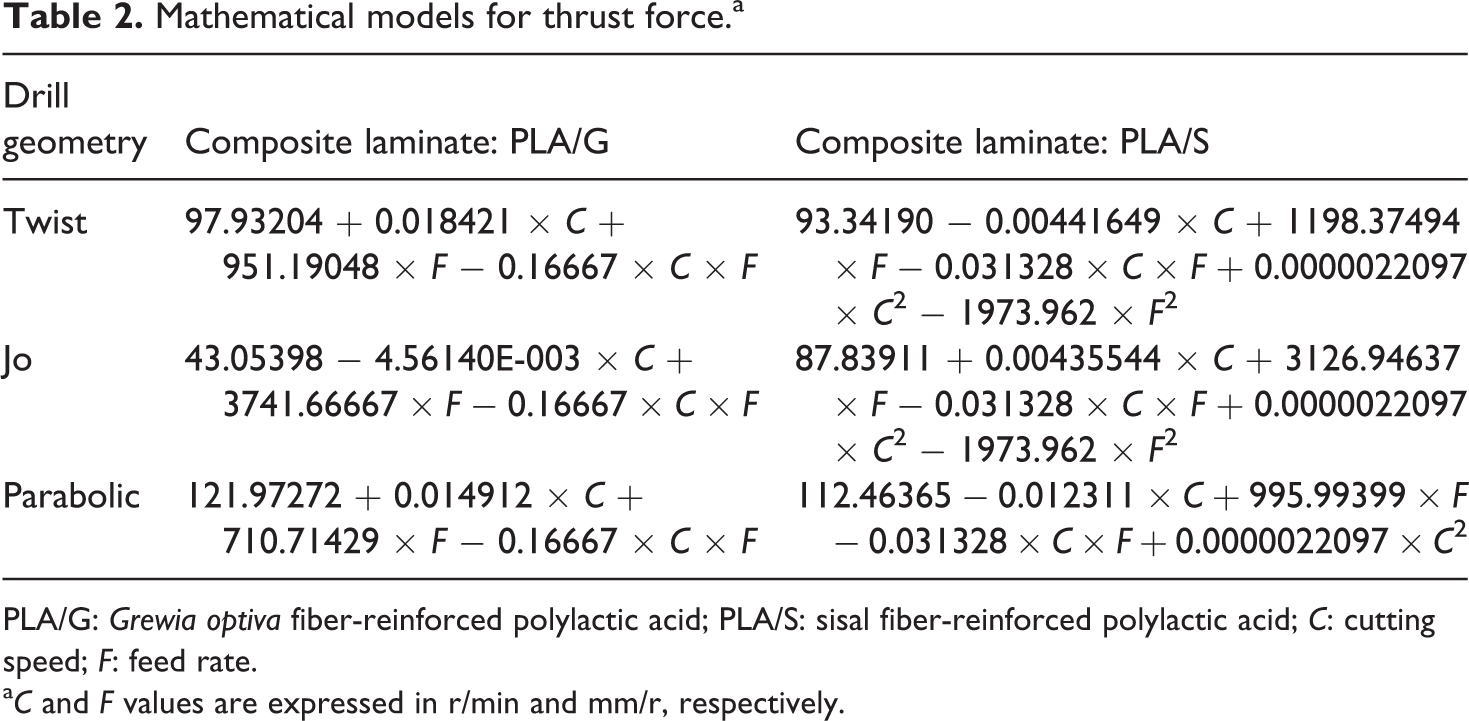
PLA/G: Grewia optiva fiber-reinforced polylactic acid; PLA/S: sisal fiber-reinforced polylactic acid; C: cutting speed; F: feed rate.
a C and F values are expressed in r/min and mm/r, respectively.
Drilling behavior of PLA/S and PLA/G composite laminates: Summary
Drilling in PLA/S and PLA/G composite laminates has shown similar trends of drilling forces with a marginal difference in magnitude. The variation of thrust force and torque for three different drill geometries used is shown in Figures 8 and 9, respectively. Drilling of PLA/G composite laminates has generated relatively higher drilling forces as compared to PLA/S composite laminates. Jo drill has consistently resulted in maximum thrust force and torque for both types of fibrous composite laminates. As both sisal and G. optiva are plant fibers, the major elements (such as amorphous and crystalline cellulose, hemicellulose, lignin, etc.) are same but in different proportions. When these fibers were used to reinforce the PLA, the developed laminates (PLA/S and PLA/G) showed similar trends of drilling forces during drilling operation due to similar elemental constituents. But the difference in magnitudes of thrust force and torque may be attributed to the difference in properties (due to different proportions of major elements), surface condition, and subsequently level of adhesion of each fiber with PLA matrix. Chandramohan and Marimuthu 30 also studied and compared the drilling behavior of different types of natural fiber-reinforced bio-epoxy composites along with their hybrids. Three types of natural fibers, namely, sisal, banana, and roselle, and their combinations were used for composite fabrication. The study reported that sisal/roselle/bio-epoxy hybrid composites showed lower fiber pull in/pull out during drilling process and concluded that incorporation of different natural fibers affected the drilling behavior of composites.
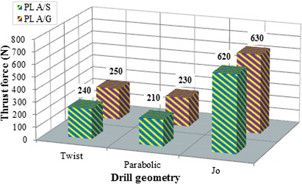
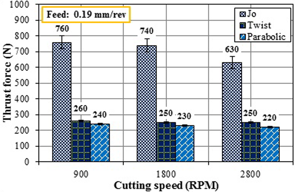
Thrust force variation for cutting speed of 1800 r/min and feed rate of 0.19 mm/r.
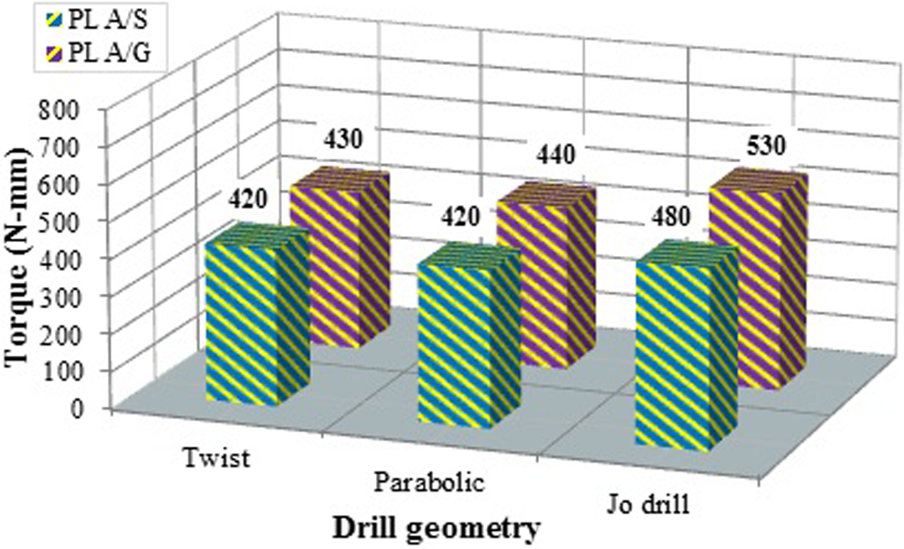
Torque variation for cutting speed of 2800 r/min and feed rate of 0.19 mm/r.
Drilling-induced damage
The nature and amount of drilling-induced damage depends upon drilling process parameters, constituents of composite, type of matrix (thermoset or thermoplastic polymer, brittle or ductile polymer), nature and characteristics of fibers, stacking sequence in the composite laminate, and so on. For glass fiber-reinforced thermoset composite laminates, the drilling-induced damage was observed to be spread all around the drilled hole. 34 Similar damage pattern has also been observed during drilling of PLA/S and PLA/G composite laminates. Typical digital images of the drilled hole in developed composites with Jo drill are shown in Figure 10(a) and (b), clearly showing the damage zone, which is spread all around the drilled hole.
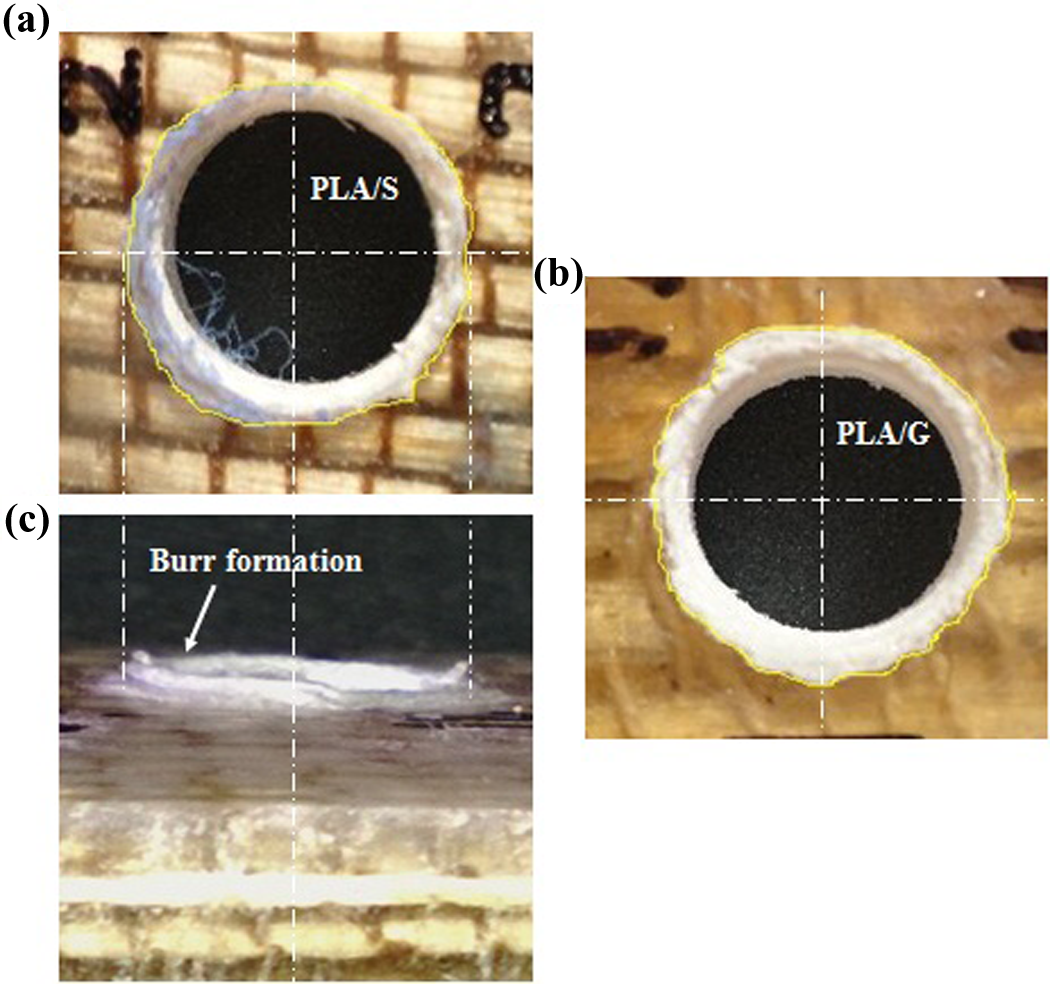
Drilling-induced damage with Jo drill for cutting speed of 1800 r/min and feed rate of 0.19 mm/r.
Digitally recorded images of the drilled holes were magnified to clearly distinguish the damaged area around the drilled hole. The pixel aspect ratio was maintained as unity so as to avoid any distortion of image that may result in invalid results. The image of drilled hole was imported in the image processing software (ImageJ 1.42) and was analyzed to calculate the damage around the drilled hole. A factor known as delamination factor is defined in equation (1) to quantify the drilling-induced damage:

where A max is the maximum area (hole area + damage area).

where D is the diameter of the hole.
The variation of delamination factor with cutting speed and feed rate is shown in Figures 11 and 12, respectively. Delamination factor has shown a decreasing trend with the increase in the cutting speed. But it increases with an increase in the feed rate for all the drill geometries. Similar variation of delamination factor with drilling process parameters was observed for both PLA/S and PLA/G composite laminates with different magnitudes. In each case, Jo drill has reported the maximum drilling-induced damage at different combinations of cutting speed and feed rates. It has been established earlier that the high value of drilling forces results in larger damage zone around the drilled hole. The fact has been substantiated by the present experimental investigation. The maximum values for the thrust force and torque were recorded with the Jo drill and subsequently it resulted in the maximum drilling-induced damage around the drilled hole. Twist and parabolic drills have reported comparable drilling-induced damage, which was always lower than Jo drill at different process parameters for both types of composite laminates. It is well established that drilling-induced damage is strongly dependent upon feed rate as compared to cutting speed. As reported by Caprino and Tagliaferri, 35 with high feed rate, drilling operation behaves like a punching phenomenon and the failure modes show the features typical of impact damage with intralaminar cracks. It has also been reported that for glass/epoxy thermoset composite laminates, Jo drill leads to minimum damage around the drilled hole. 34 But in this study of thermoplastic-based biocomposite laminates, a reverse trend has been observed. Jo drill has induced maximum damage during the drilling operation. It may be due to the fact that Jo drill performs the complete drilling operation in two steps. Initially, the primary cutting edges generate a pilot hole and finally the secondary cutting edges enlarge the predrilled pilot hole. Due to the heat generation in the first stage, the matrix (PLA) softens and complete cutting or shearing of composite laminates does not take place in the second stage. PLA is a brittle thermoplastic biopolymer that has low T g (58°C). The thermomechanical stress developed during drilling due to the generation of temperature and induced forces may cause elongating or movement of polymer chains. Therefore, instead of being cut, the material in the bottom layers is extruded along with the Jo drill thus leading to a larger damage zone as well as formation of burr (Figure 10(c)). A comprehensive analysis of the heat generation and distribution in the tool–workpiece interaction zone is necessary to completely understand the drilling-induced damage in the thermoplastic composite laminates, both qualitatively and quantitatively.
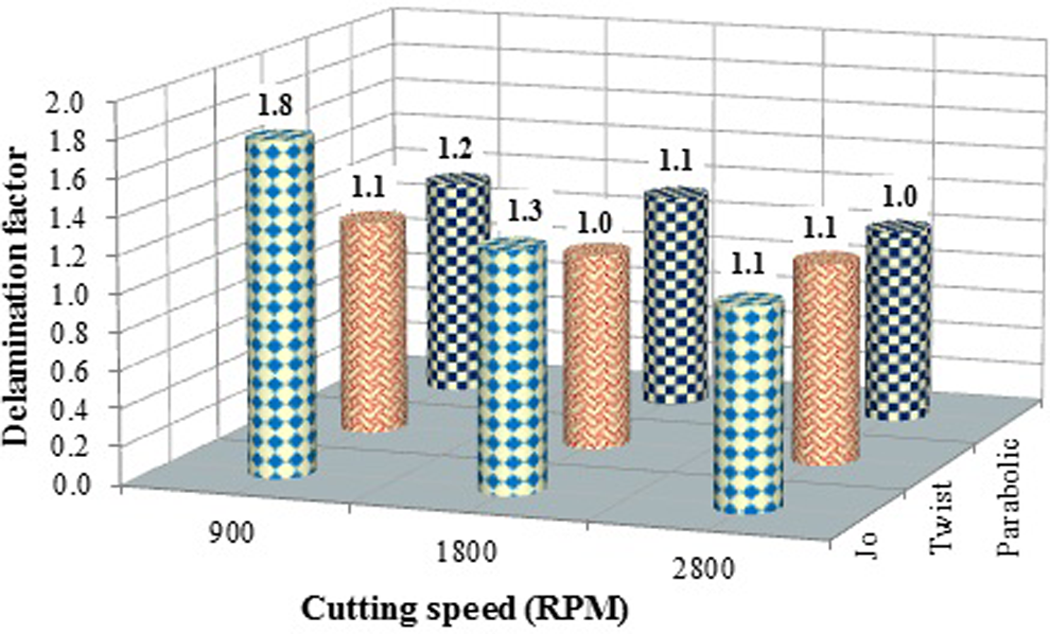
Variation of delamination factor with cutting speed for PLA/G composites for feed rate of 0.12 mm/r.
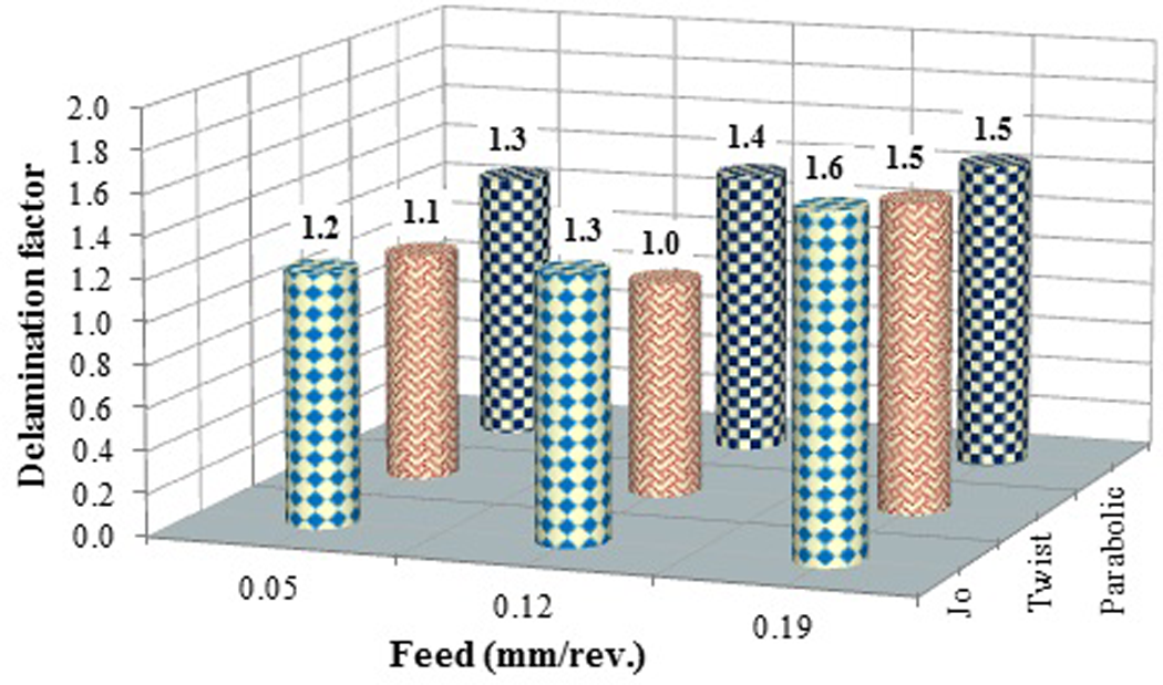
Variation of delamination factor with feed rate for PLA/S composites for cutting speed of 2800 r/min.
Conclusion
In the present experimental investigation, drilling behavior of PLA-based green composite laminates was studied at different combinations of drilling process parameters. The following conclusions can be drawn: The thrust force and torque decrease with increase in the cutting speed and increase with increase in feed rate during drilling of developed composite laminates. The drilling operation with Jo drill leads to maximum thrust force and torque at all combinations of cutting speed and feed rate. The drilling-induced damage shows a decreasing trend with cutting speed and it increases with increase in feed rate. Maximum drilling-induced damage was observed with Jo drill. Therefore, Jo drill is not recommended for drilling of PLA/S and PLA/G composite laminates within the experimental domain. The cutting forces and drilling-induced damage showed similar behavior for both types of composite laminates developed except the magnitudes that may be due to the type and nature of fibers. It can be concluded from the results that drill geometry and feed rate are critical parameters in drilling of green composite laminates for generating damage-free holes. RSM technique can be used to accurately predict the drilling forces in drilling of PLA/S and PLA/G composite laminates within the range of variables studied and drilling process parameters can be optimized to reduce the drilling forces and subsequently drilling-induced damage. The optimum drill point geometry for synthetic fiber composite laminates is not suitable for natural fiber-reinforced laminates because of the difference in the constituents and the material removal mechanisms.