
Abstract
Within the scope of experiments, five kinds of biaxial weft-knitted (BWK) fabrics with various knitting techniques (plain, interlock, tuck, tuck-miss, and interlock2) were used as reinforcement systems to fabricate thermoplastic composites with polypropylene (PP) resin yarn. Then, the final composite became BWK composites with various knitting types. The mechanical properties of composites were investigated by conducting tensile, three-point bending, and three-point bending impact tests on specimens. In all specimens, PP was commingled with glass yarn. Glass was used as reinforcement. Fiber volume fraction (Vf) of weft fibers of the interlock2 was the highest, and the length of straight part of loop shape was the longest in the interlock2 compared with the other four types of specimens. Because of the higher Vf of the BWK composites with the interlock2, tensile, three-point bending, and three-point bending impact properties of the interlock2 was higher than the other four types (plain, interlock, tuck, and tuck-miss) of composite structures.
Keywords
Introduction
Knitted composites are generally considered to have inferior mechanical properties due to their highly looped structure and low fiber volume fraction (V f). However, the attractive properties, such as those requiring high-energy absorption or good impact resistance, or in cases where the component is complex in shape and demands exceptional formability, can be achieved by using knitted composites. 1
In order to improve the mechanical properties, such as strength and stiffness, of weft-knitted fabric, straight yarns both in weft and warp directions can be integrated. These types of reinforcements are called biaxial weft-knitted (BWK) structures. Weft and warp yarn layers are held together by a stitching yarn system in BWK fabrics. Reinforcing yarns, for example, glass fiber (GF) or aramid fiber, can be used within all yarn systems. 2 The tensile properties of the BWK thermoset composites were reported by Demircan et al. 3
Nowadays, thermoplastic composites are being used in various industries such as automotive, wind turbines, and so on. The most important advantages of thermoplastics are their potential for rapid, low cost, and mass production of reinforced composites. On the other hand, the very high viscosity (usually 500–5000 Pa·s) of thermoplastic composites makes the processing of thermoplastic matrix composites difficult. Therefore, some techniques, such as commingled yarn, were developed in order to improve processability of thermoplastic composites. The matrix fiber will be mixed with reinforcing fiber in commingled yarn technique and this technique proved to be a cost-effective method for processing of thermoplastic composites. 4,5 Therefore, the commingled yarn technique was chosen in order to fabricate the BWK preforms. Some research has been carried out to find out consolidation quality of GF/polypropylene (PP)-commingled yarn-based composites. 6,7
Knitted fabric-reinforced thermoplastic composites with commingled fibers were studied by some researchers. 8,9 The tensile properties of knitted fabric-reinforced composites made from GF/PP commingled yarn with different loop densities were investigated by Zaixia et al. 4 They found that the tensile strength of the composites increase followed by a slight decrease as the loop density of preform increases. Rios et al. 10 studied the damage development and tensile properties of weft-knitted composites. They tested one layer milano weft-knitted glass fabric-reinforced composites at various angles to loading direction. Mechanical properties of knitted fabric composites were investigated by Hamada et al. 11 They conducted tensile, three-point bending, and plate-bending tests on knitted composites. Tensile, three-point bending, and impact properties of textile-inserted PP/PP-knitted composites using injection–compression molding were reported by Khondker et al. 12 The tensile properties of weft-knitted composites for energy absorption were studied by Xue et al. 13 They described correlation between fabric structure (e.g. loop height and width, number of wale or course per unit length, etc), matrix damage, and materials properties. Fabrication and mechanical properties of aramid/nylon plain-knitted composites were reported by Khondker et al. 14 They investigated the mechanical properties of aramid/nylon and aramid/epoxy composites and their relationships to the fiber/matrix interfacial adhesion. The effect of architecture on the mechanical properties of knitted composites was reported by Anwar et al. 15 They investigated tensile and compression properties of three milano ribs and one rib weft-knit glass fabric reinforcement. Moreover, only a few numbers of contributions were made on mechanical properties of BWK composite, 16–18 Demircan et al. 19,20 reported bending and impact properties of BWK thermoset and thermoplastic composites.
In the literature, contributions about the mechanical properties of knitted composites were reported, which were explained above. However, only a few numbers of contributions were made on the mechanical properties of the BWK thermoplastic composites with various knitting techniques. The purpose of this research is to characterize the mechanical properties of the BWK textile composites. Within this study, we investigated tensile, three-point bending, and three-point bending impact properties of the BWK thermoplastic composites with various knitting techniques. The obtained results of this study can be used to design of new textile preforms during development of different composite materials.
Experimental procedures
Composites constituents
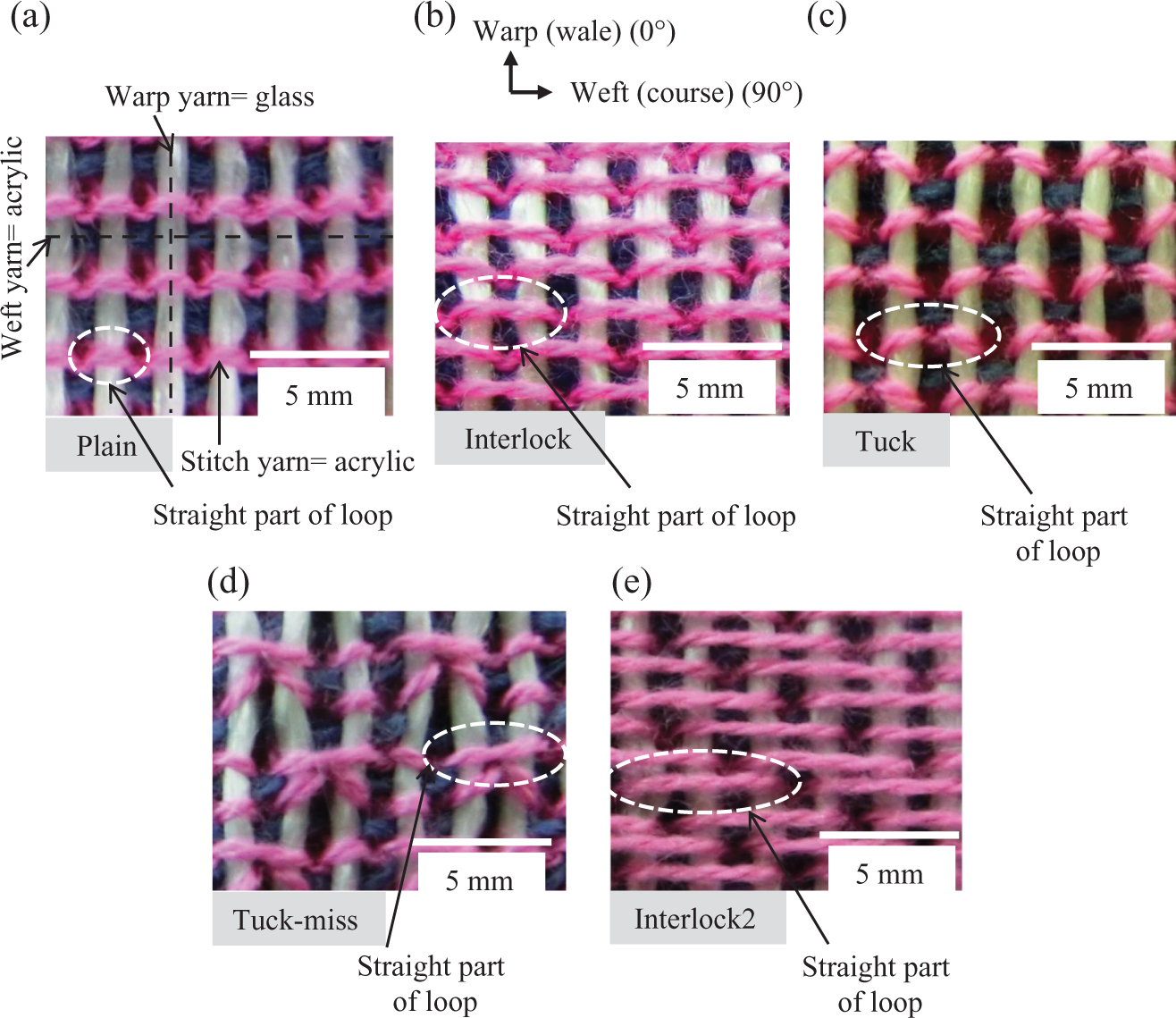
In all thermoplastic composite panels, the glass was used as reinforcement and the PP was used as resin yarn. The GF/PP-commingled yarns were used as warp (410 tex), weft (410 tex), and stitch yarns (138 tex) in the BWK fabrics. The volume content of the GFs was 52% and that was for the PP fibers 48% in the warp and weft-commingled yarns. The volume content of the GFs was 27% and was 73% for the PP fibers in the stitch-commingled yarns. Schematic drawing of the BWK fabric is shown in Figure 1(a) to (d). Figure 1(a) depicts the warp and weft yarns. The knitted fabric with stitch yarn is shown in Figure 1(b). Figure 1(c) and (d) shows the BWK fabric with warp, weft, and stitch yarns. Five types of the BWK fabrics with the GF/PP-commingled yarns with the various knitting techniques (plain, interlock, tuck, tuck-miss, and interlock2) were produced on a flat-bed knitting machine (Shima Seiki Mfg, Ltd, Japan). Figure 2(a) to (e) shows the photographs of the BWK fabrics. The schematic drawings of the BWK fabrics are shown in Figure 3(a) to (e). Plain knitting is a basic knitting stitch in which each loop is drawn through other loops to the right side of the fabric (Figure 3(a)). Interlock was originally derived from rib but requires a special arrangement of needles knitting back-to-back in an alternate sequence of two sets, thus hiding the appearance of the reverse loops (Figure 3(b) and (e)). A tuck stitch is composed of a held loop, one or more tuck loops, and knitted loops. It is produced when a needle holding its loop also receives the new loop, which becomes a tuck loop (Figure 3(c)). A miss stitch, welt stitch, or float stitch is composed of a held loop, one or more float loops, and knitted loops. It is produced when a needle holding its old loop fails to receive the new yarn that passes, as a float loop, to the back of the needle. Tuck-miss stitch was a combination of the tuck and miss stitch together (Figure 3(d)). 21
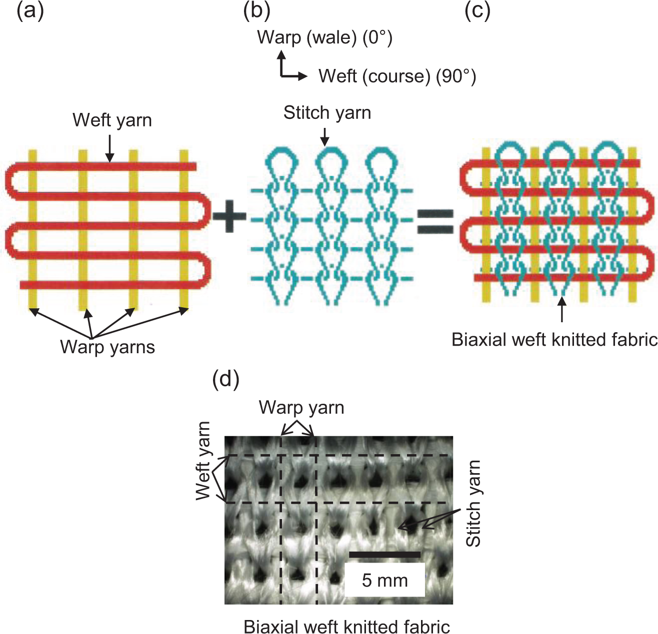
Schematic drawing of the BWK fabric: (a) the warp and weft yarns, (b) the knitted fabric with stitch yarn, and (c,d) the BWK fabric with warp, weft, and stitch yarns.
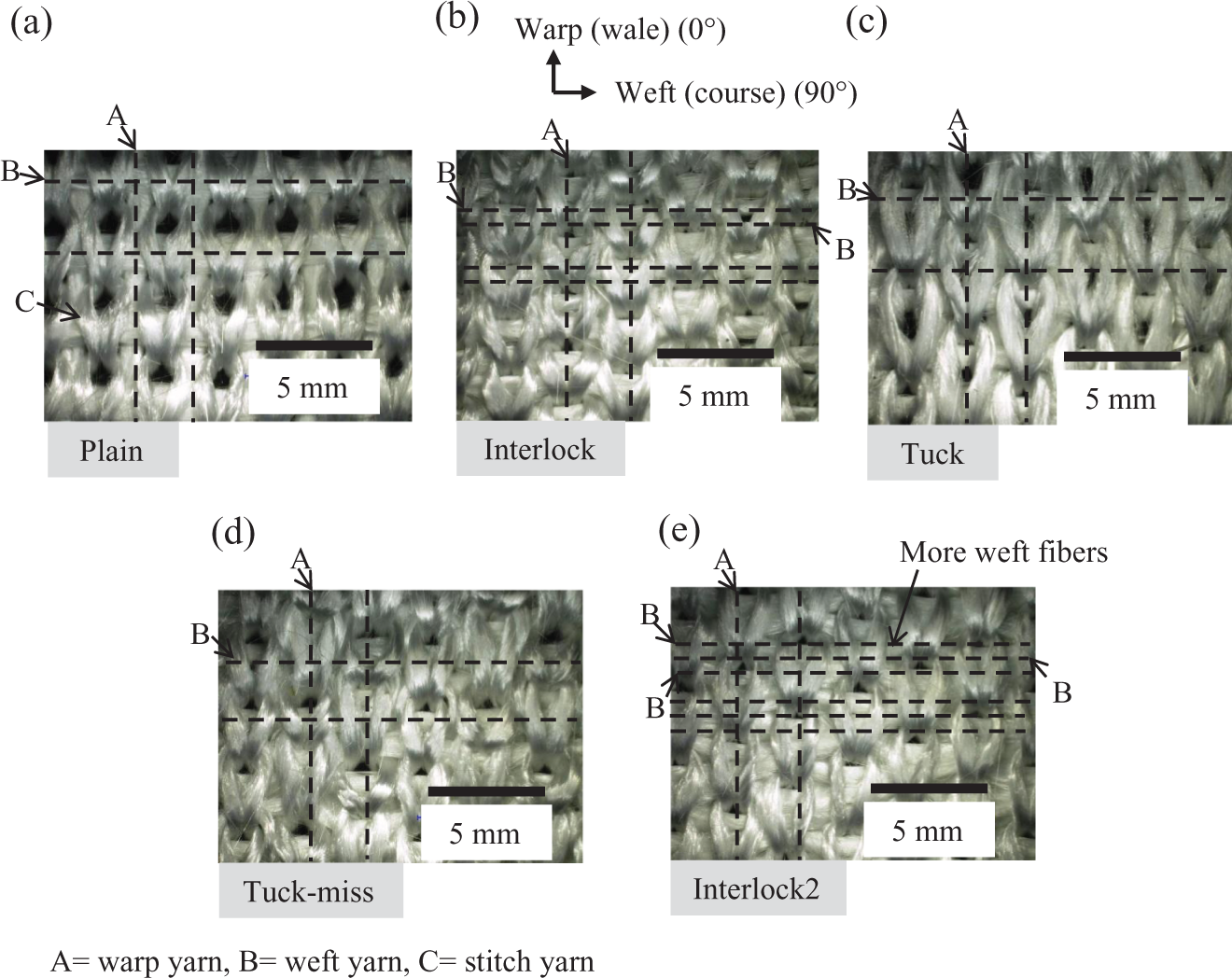
Photographs of the BWK fabrics: (a) plain, (b) interlock, (c) tuck, (d) tuck-miss, and (e) interlock2.
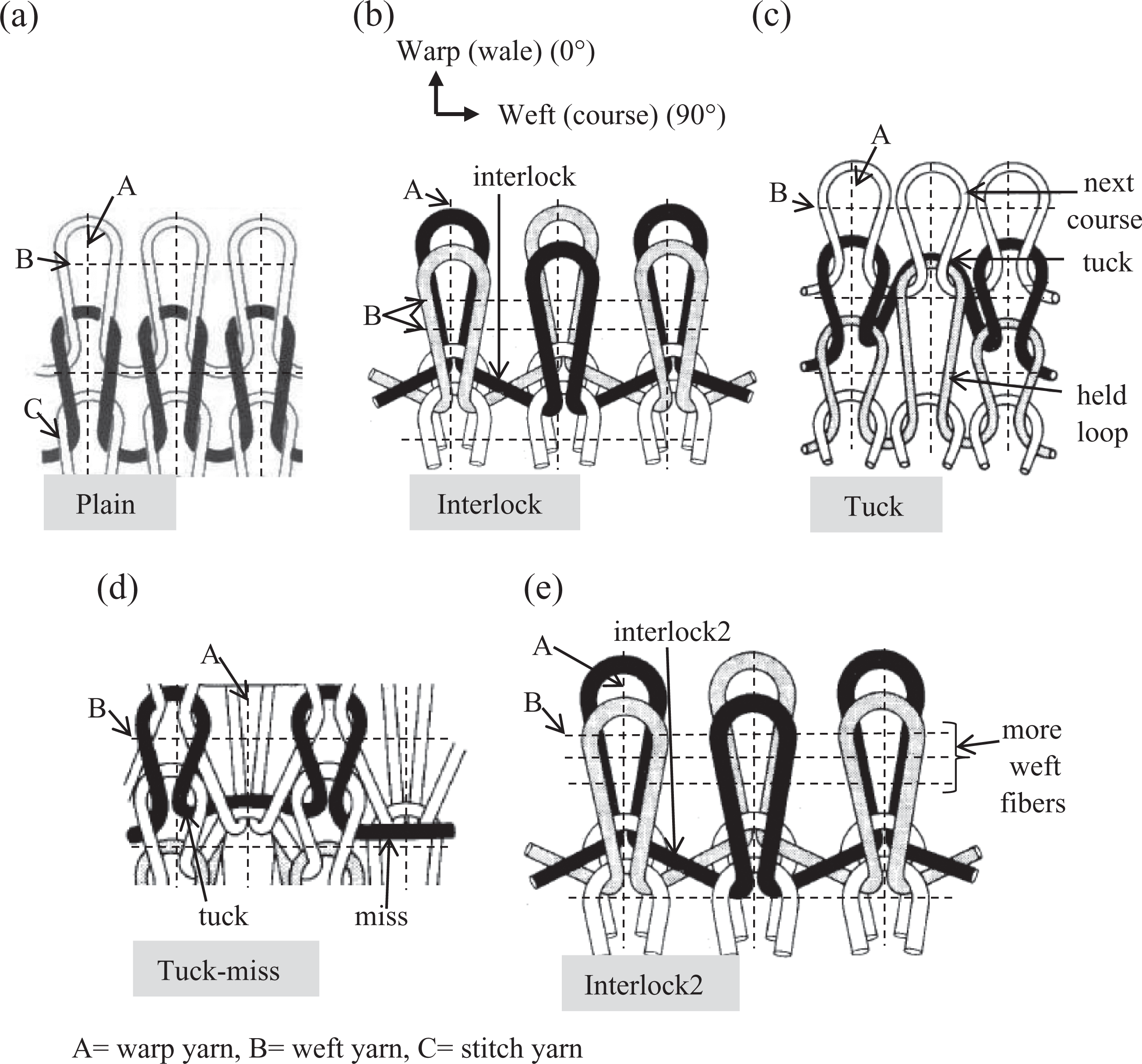
Schematic drawings of the BWK fabrics: (a) plain, (b) interlock, (c) tuck, (d) tuck-miss, and (e) interlock2.
We made experiments by changing the knitting structure techniques (plain, interlock, tuck, tuck-miss, and interlock2) as shown in Figure 3(a) to (e). For example, in the interlock2 (Figure 3(e)), the straight part of loop shape in weft direction was the longest compared with the other four types of knitting. Also, the loop length of interlock2 was longer than interlock. Therefore, more weft fibers could be inserted in the interlock2.
Fabrication method
Due to vacuum-heating process of the BWK preforms, good interaction between fiber and resin could be provided. Therefore, the BWK preforms were stayed in a vacuum heater at 80°C for 6 h before fabrication of composites. BWK composites with 2 and 10 layers were fabricated on hot-press compression machine (Figure 4(a)). Figure 4(b) shows the lower- and upper mold dies. During fabricating of the BWK composites, the PP resin fibers in the BWK fabric were melted and disappeared and became resin. Only the GF warp, weft, and stitch fibers were stayed in the BWK composites. The stacking sequence of 10 layer composites was written in a symmetric laminate code. Fabrics were cut in the weft direction; attached in a metallic frame, and put in the molding die. The molding pressure, temperature, and time were 3 MPa, 220°C, and 13 min. Later, mold was cooled until it comes to the room temperature around 35°C. Fiber V fs were found out by performing burn-out tests.
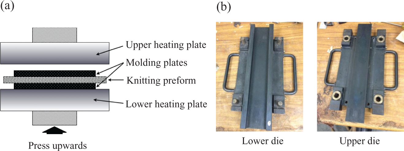
(a) Schematic drawing of the hot-press compression machine; (b) lower and upper mold dies.
Table 1 shows the fiber V f and thickness of 2 and 10 layer-BWK composites. The V f of weft yarn in the BWK composites were increased by changing the knitting technique, and interlock2 had the highest weft fiber V f in both 2 and 10 layers (19.1 and 18.1%), whereas, the volume fraction of weft yarn in the plain BWK composites had the lowest in both 2 and 10 layers (11 and 11%).
Fiber V f and thickness of composites.
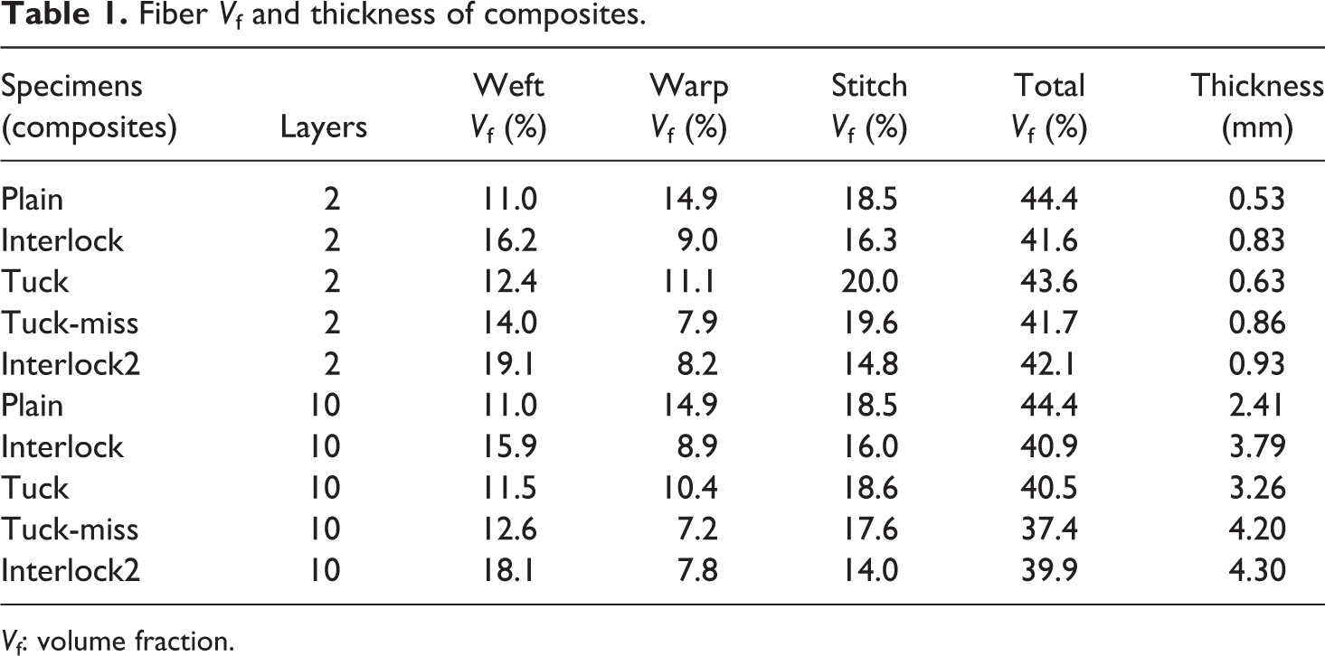
V f: volume fraction.
Mechanical characterization
Tensile tests were conducted on two layers and three-point bending tests were conducted on 10 layers BWK composites. Tensile and three-point bending tests were performed on the specimens according to ASTM-D303 standard in the course (weft yarn) direction. The measurements of tests were performed using universal testing machine type 55R4206 (Instron, Japan), under displacement control with 1 mm/min speed. Figure 5(a) shows the geometry of the specimen from tensile test. In this figure, laminate and aluminum thickness is shown with t c and t Al. The value of t Al tabs was 0.5 mm. The composite coupons had a nominal dimension 200 × 20 mm2 for tensile test. Figure 5(b) shows the geometry of the specimen from three-point bending test. Because of the different thickness of the 10 layers BWK specimens, the span lengths of the specimens were changed from 40 to 72 mm. The width of the specimens was 15 mm.
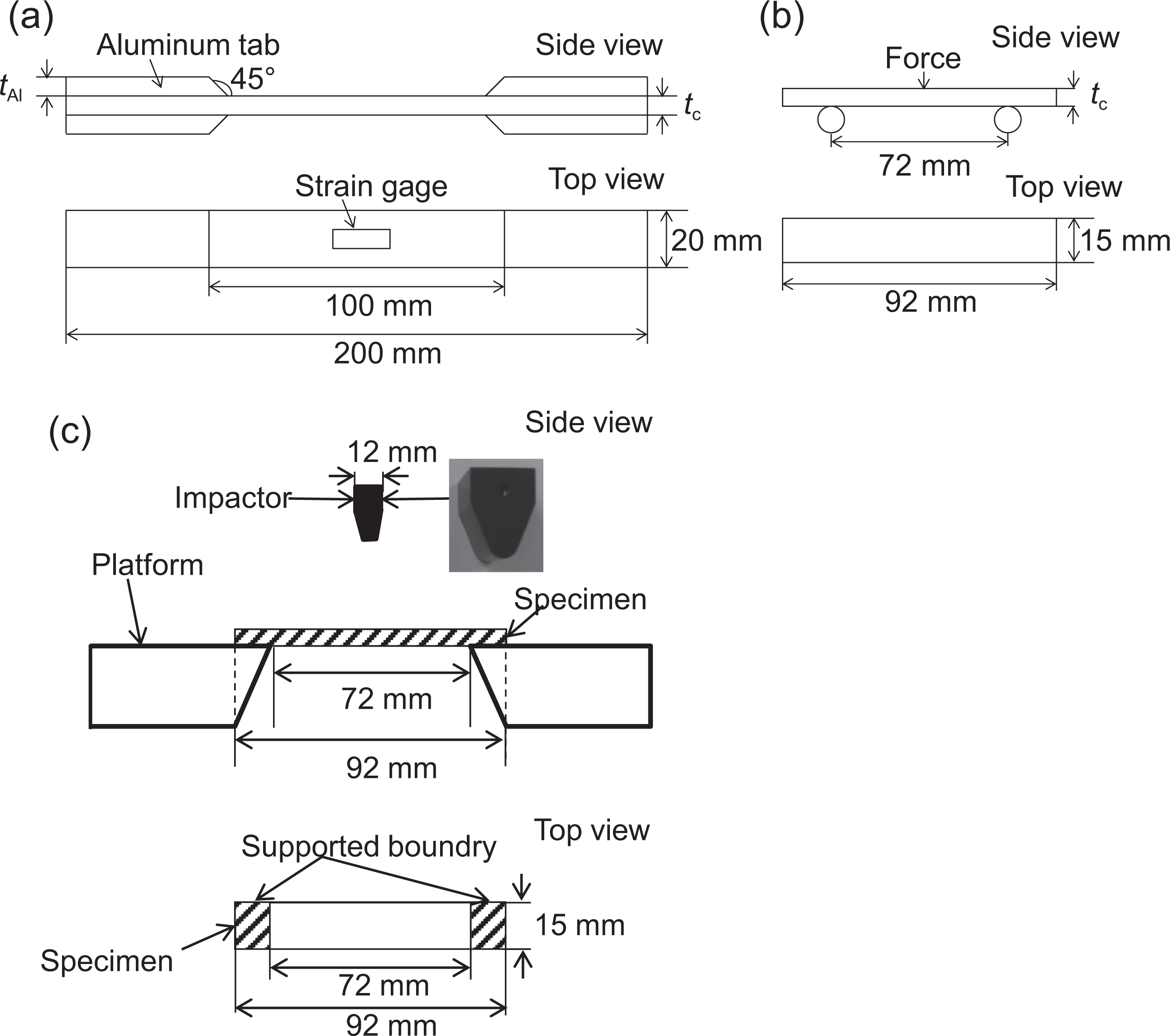
Geometry of the specimen (a) tensile test, (b) three-point bending test, (c) three-point bending impact test.
Figure 5(c) shows the test set up and geometry of the specimen from three-point bending impact test. The three-point bending impact tests were conducted on 10 layers BWK specimens according to JIS-K7084 standard in the course (weft) direction. The three-point bending impact damages were inflicted on different specimens in a drop-weight test using a Dynatup 9250HV-type universal testing machine (Instron). The drop-weight was used as an impactor for the tests. The weight of the impactor was 6490 g and the incident impact energy was 20 J for the three-point bending impact test. The composite coupons had a nominal dimension 92 × 15 mm2 for three-point bending impact test. Test span length was 72 mm.
Results and discussions
Tensile properties
The stress–strain curves of the BWK composites during tensile test are shown in Figure 6(a). From these curves, it can be seen that tensile stress with the BWK composites increases linearly with increase in the strain and was followed by a sudden drop in a stress value corresponding to the ultimate failure of the composite. The specimen with the interlock2 showed the highest tensile stress and the tensile ultimate strain, whereas the plain showed the lowest tensile stress and the tensile ultimate strain in the weft direction. The ultimate strain of the specimens with the interlock2 was about 1.5 times higher than that was with the plain in the weft direction.
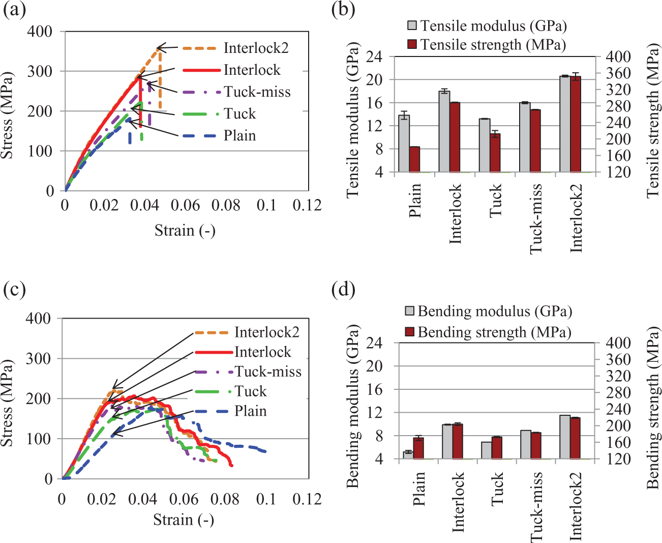
(a,b) Tensile test results, and (c,d) three-point bending test of the BWK composites with various knitting techniques.
Figure 6(b) shows tensile modulus and strength results of the BWK composites. The highest tensile modulus and strength was obtained by the interlock2 composites in the weft direction (20.6 GPa and 351 MPa). The tensile modulus and strength of the interlock2 composites was 33 and 48.4% higher than the BWK composites with the plain (13.8 GPa and 181 MPa) in the weft direction.
The possible reason of obtained higher tensile test results with the interlock2 composites would be the highest weft fiber volume fraction (19.1%) than the BWK composites with the plain, interlock, tuck, and tuck-miss (11, 16.2, 12.4, and 14%).
Three-point bending properties
Figure 6(c) and (d) shows the results of the three-point bending test with various knitting types. The flexural strength yielded different trend compared to the tensile test results in the weft direction. The tensile modulus and strength of the BWK composites (Figure 3(b)) were higher than the flexural modulus and strength of the BWK composites (Figure 6(b)) in the weft (course) direction. Different failure mechanism could be responsible for this different trend. A measure of the resistance to deformation of the composite in bending is called flexural modulus. Flexural strength and stiffness is mainly controlled by the strength of the reinforcement fibers. The BWK composites with the interlock2 exhibited superior flexural modulus and strength (11.5 GPa and 219 MPa) compared with other tested specimens. The BWK composites with the interlock2 exhibited 55 and 22% higher flexural modulus and strength than that was with the plain (5.2 GPa and 170 MPa) in the weft direction.
Because of the higher fiber V f of the BWK composites with the interlock2 in the weft direction, the flexural properties with the interlock2 was the highest compared with the other tested BWK composites.
Three-point bending impact properties
Figure 7 shows three-point bending impact test results of the BWK thermoplastic composites, load–displacement curves during three-point bending impact test. The load–displacement graphics showed that the highest maximum load was achieved by the interlock2 (0.8 kN), whereas the plain had the lowest maximum load about 0.2 kN in the weft direction.
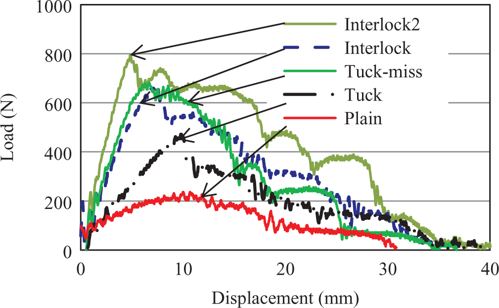
Three-point bending impact test results, load–displacement curves during three-point bending impact test.
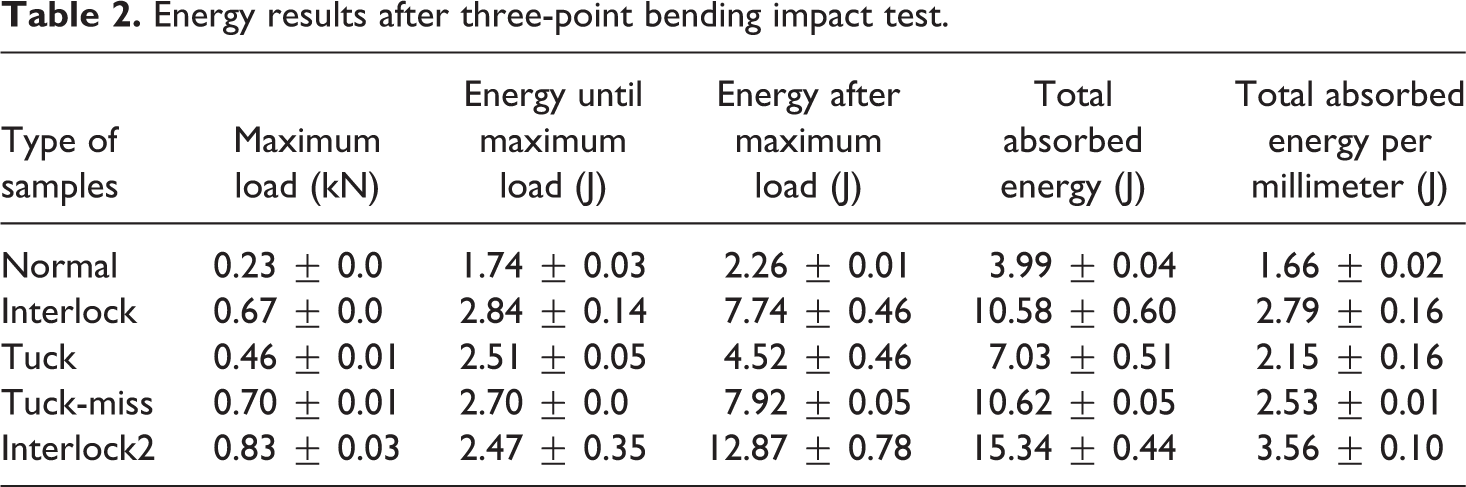
Table 2 shows energy results after three-point bending impact test. The interlock2 had the highest impact properties and total absorbed energy (15.3 J) compared with the other four specimens. After the interlock2 specimens, the tuck-miss and interlock specimens had almost same total absorbed energy that was around 10.6 J. Changing the structure of knitting makes the fabric stronger in three-point bending impact tests. Because the density and V f of weft yarn were increased in the BWK composites with the interlock2 knitting, the strength and the capacity of impact shock absorption of the BWK composite with the interlock2 were improved. With the various knitting structure techniques, strength design in the fabric could be controlled. The interlock2 type of composites had almost four times higher maximum load and impact energy compared with the plain knitting (0.2 kN and 3.9 J; Figure 7 and Table 2). The energy result after maximum load was higher than the energy result until maximum load in all specimens. This result indicates that most of the energy was absorbed after maximum load. Further, total energy results were recalculated with same thickness of specimens and found the interlock2 absorbed more total energy (3.5 J/mm) than the other four types of composites which is shown in Table 2.
Energy results after three-point bending impact test.
Relationship between total absorbed energy from three-point bending and from three-point bending impact tests
The relationship between the total absorbed energy from the three-point bending test and from the three-point bending impact test is shown in Figure 8. The area under load–displacement curves gives the absorbed energy during the three-point bending test. Initiation energy was found out to calculate the area under load–displacement curve until maximum load and that was for propagation energy after maximum load. The total energy was the total value of the initiation and propagation energy. This graphic showed that there was a good relationship between the total absorbed energy from the three-point bending test and from the three-point bending impact test. The total absorbed energy from the three-point bending test increased with increasing the total absorbed energy from the three-point bending impact test. The total absorbed energy from the three-point bending impact tests was much higher than that was from the three-point bending tests. Because of the good relationship between the three-point bending test and the three-point bending impact tests, the fracture behavior of specimens during conducting of both tests could be similar.
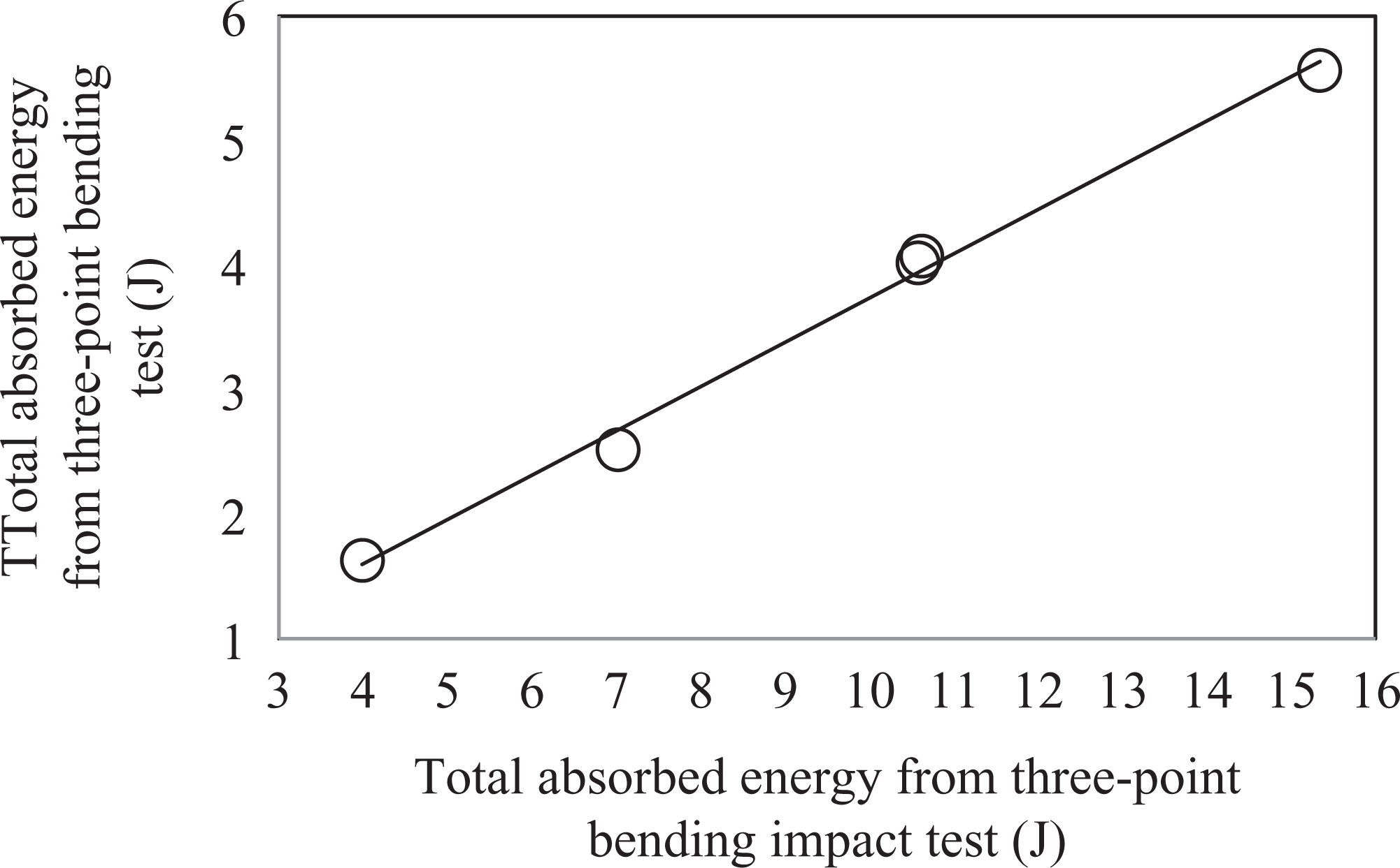
Relationship between total absorbed energy from three-point bending test and from three-point bending impact test.
Relationship between energy after maximum load and fiber V f of composites
Relationship between energy after maximum load and fiber volume fraction of composites in the weft direction is shown in Figure 9. Total energy after maximum load increased with increasing of volume fraction of composites in the weft direction. The interlock2 had the highest fiber volume fraction (18.1%) and energy after maximum load (12.9 J) in the weft direction, whereas the plain had the lowest fiber volume fraction (11%) and energy after maximum load (2.3%) in the weft direction.
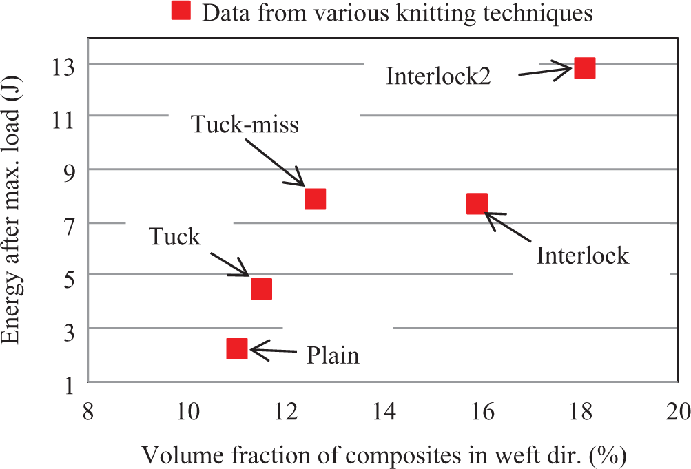
Relationship between energy after maximum load and fiber volume fractions of composites.
Figure 10(a) to (e) shows back face photos of the BWK fabrics with plain, interlock, tuck, tuck-miss, and interlock2. The BWK fabric, which is shown in Figure 10(a) to (e), was model structure with different materials. And in these materials the GF/PP-commingled fibers (400 tex) were used as warp yarns (white color), acrylic fibers were used as weft yarn (blue color; 36/2 Nm), and stitch yarn (red color; 36/2 Nm). The various length of straight part of the loop shape could be seen in Figure 10(a) to (e). The photo of the interlock2 (Figure 10(e)) shows the longest length of straight part of the loop shape compared with the other specimens, whereas the photo of plain-knitting shows the shortest length of straight part of the loop shape (Figure 10(a)). The straight part of the loop shape would probably contribute to increase the energy after maximum load. So, these results show that the various knitting techniques, such as interlock2, would be helpful to increase the impact absorption capacity of the BWK composites.
Back face photos of the BWK fabrics with (a) plain; (b) interlock; (c) tuck; (d) tuck-miss, and (e) interlock2.
Conclusion
Our study showed that the mechanical properties, such as tensile, three-point bending, and three-point bending impact, of the BWK composites could be improved by changing knitting techniques. The interlock2 had the highest tensile, three-point bending, and three-point bending impact properties compared with the plain, interlock, tuck, and tuck-miss specimens. Because of the highest weft fiber V f in the BWK composites with the interlock2, the mechanical properties were improved compared with the other four kinds of specimens in the weft direction. The good agreements between the total absorbed energy from three-point bending test and from three-point bending impact test supported our test results. The relationship between energy after maximum load and V f of composites in the weft direction was also studied, and it was found that the total energy after maximum load increased with increasing of the V f of composites in the weft direction. In the future study, we will try to fabricate three-dimensional BWK composites using WHOLE GARMENT® technology which is available on weft-knitting machines.
Footnotes
Funding
The authors specially thank Prof. Hiroyuki Hamada and Assoc. Prof. Mohamed S Aly-Hassan, Kyoto Institute of Technology, Japan, for their help and support.